AIR-CONDITIONER - Heronhill Air Conditioning Ltd
AIR-CONDITIONER - Heronhill Air Conditioning Ltd
AIR-CONDITIONER - Heronhill Air Conditioning Ltd

You also want an ePaper? Increase the reach of your titles
YUMPU automatically turns print PDFs into web optimized ePapers that Google loves.
FILE NO. SVM-02008SERVICE MANUAL<strong>AIR</strong>-<strong>CONDITIONER</strong>UNDER CEILING / CONSOLE TYPERAS-18UFHP-E / RAS-18UAH-ERAS-18UFP-E / RAS-18UA-ERAS-18UFPX / RAS-18UAXRAS-18UFP-AR / RAS-18UA-ARRAS-18UFPX-T2 / RAS-18UAX-T2RAS-24UFHP-E / RAS-24UAH-ERAS-24UFP-E / RAS-24UA-ERAS-24UFPX / RAS-24UAXRAS-24UFP-AR / RAS-24UA-ARRAS-24UFPX-T / RAS-24UAX-T18 Class24 ClassMar., 2002
CONTENTSFILE NO. SVM-020081. SPECIFICATIONS1-1 18 Class1-2 24 Class2. CONSTRUCTION VIEWS2-1 Indoor Unit2-2 Outdoor Unit (RAS-18UAH-E, RAS-18UA-E, RAS-18UAX, RAS-18UA-AR)2-3 Outdoor Unit (RAS-18UAX-T2, RAS-24UAH-E, RAS-24UA-E, RAS-24UAX, RAS-24UA-AR,RAS-24UAX-T)3. WIRING DIAGRAM3-1 RAS-18UFHP-E / RAS-18UAH-E3-2 RAS-18UFP-E / RAS-18UA-ERAS-18UFPX / RAS-18UAX3-3 RAS-18UFP-AR / RAS-18UA-AR3-4 RAS-24UFHP-E / RAS-24UAH-E3-5 RAS-18UFPX-T2 / RAS-18UAX-T2RAS-24UFP-E / RAS-24UA-ERAS-24UFPX / RAS-24UAXRAS-24UFP-AR / RAS-24UA-ARRAS-24UFPX-T / RAS-24UAX-T4. SPECIFICATION OF ELECTRICAL PARTS4-1 Indoor Unit4-2 Outdoor Unit (RAS-18UAH-E)4-3 Outdoor Unit (RAS-18UA-E, RAS-18UAX)4-4 Outdoor Unit (RAS-18UA-AR)4-5 Outdoor Unit (RAS-18UAX-T2)4-6 Outdoor Unit (RAS-24UAH-E)4-7 Outdoor Unit (RAS-24UA-E, RAS-24UAX, RAS-24UA-AR)4-8 Outdoor Unit (RAS-24UAX-T)5. REFRIGERATION CYCLE DIAGRAM5-1 RAS-18UFHP-E / RAS-18UAH-E5-2 RAS-18UFP-E / RAS-18UA-ERAS-18UFPX / RAS-18UAX5-3 RAS-18UFP-AR / RAS-18UA-AR5-4 RAS-18UFPX-T2 / RAS-18UAX-T25-5 RAS-24UFHP-E / RAS-24UAH-E5-6 RAS-24UFP-E / RAS-24UA-ERAS-24UFPX / RAS -24UAXRAS-24UFP-AR / RAS-24UA-ARRAS-24UFPX-T / RAS-24UAX-T6. CONTROL BLOCK DIAGRAM6-1 RAS-18UFHP-E, RAS-24UFHP-E6-2 RAS-18UFP-E, RAS-18UFPX, RAS-18UFP-AR, RAS-18UFPX-T2RAS-24UFP-E, RAS-24UFPX, RAS-24UFP-AR, RAS-24UFPX-T– 1 –
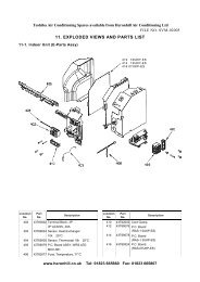
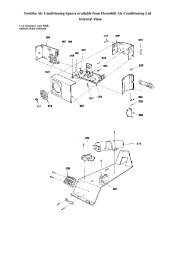
FILE NO. SVM-020087. OPERATION DESCRIPTION7-1 Outline of <strong>Air</strong> Conditioner Control7-2 Description of Operation Circuit7-3 Hi POWER Mode7-4 High-Temperature Limit Control7-5 Low-Temperature Limit Control7-6 Defrosting Operation7-7 Auto Restart Function7-8 Filter Check Lamp8. INSTALLATION PROCEDURE8-1 Safety Cautions8-2 Installation Diagram of Indoor and Outdoor Units8-3 Installation8-4 Indoor Unit8-5 Outdoor unit8-6 How to Set Remote Control Selector Switch8-7 How to Use Drain Pump Kit of Option8-8 Others9. TROUBLESHOOTING CHART9-1 Troubleshooting Procedure9-2 Basic Check Items9-3 Primary Judgement9-4 Self-Diagnosis by Remote Control (Check Code)9-5 How to Diagnose Faulty Parts9-6 Troubleshooting for Indoor Unit9-7 Troubleshooting for Wiring (Interconnect Cable and Serial Signal Wire)9-8 Troubleshooting for P.C. Board9-9 Troubleshooting for Remote Control10. PARTS REPLACEMENT10-1 Indoor Unit10-2 Outdoor Unit (RAS-18UAH-E, RAS-18UA-E, RAS-18UAX, RAS-18UA-AR)10-3 Outdoor Unit (RAS-24UAH-E, RAS-18UAX-T2, RAS-24UA-E, RAS-24UAX, RAS-24UA-AR,RAS-24UAX-T)11. EXPLODED VIEWS AND PARTS LIST11-1 Indoor Unit (E-Parts Assy)11-2 Indoor Unit (RAS-18-UFHP-E, RAS-18UFP-E, RAS-18UFPX, RAS-18UFP-AR)11-3 Indoor Unit (RAS-18UFPX-T2, RAS-24UFHP-E, RAS-24UFP-E, RAS-24UFPX,RAS-24UFP-AR, RAS-24UFPX-T)11-4 Outdoor Unit (RAS-18UAH-E)11-5 Outdoor Unit (RAS-18UA-E, RAS-18UAX)11-6 Outdoor Unit (RAS-18UAX-T2, RAS-24UA-E, RAS-24UAX, RAS-24UA-AR, RAS-24UAX-T)11-7 Outdoor Unit (RAS-24UAH-E)– 2 –
1. SPECIFICATIONSFILE NO. SVM-020081-1ITEMMODELRAS-18UFP-E/18UA-ERAS-18UFHP-E/18UAH-ERAS-18UFPX/18UAXRAS-18UFP-AR/18UA-AR RAS-18UFPX-T2/18UAX-T2Cooling Heating CoolingCapacity kW 220V 240V 220V 240V 220V 240V 220V 240V 220V5.00 5.70 5.80 5.20 5.35 5.15Phase1∅Power source V 220 – 240 220Hz 50Power consumption W 2000 2130 1830 2000 2000 2120 2020 2140 1610Power factor % 95 87 93 84 96 87 95 86 98Running currentIndoor A 0.40 0.40 0.40 0.40 0.40 0.40 0.40 0.40 0.45Outdoor A 9.20 9.85 8.50 9.50 9.10 9.70 9.30 10.00 7.00Starting current A 40 35Moisture removal lit/h 2NoiseIndoor (H/M/L) dB 43/39/36 46/41/36Outdoor dB 52 53 53 54 51 52 52 53 56RefrigerantName of refrigerant R-22Rated amount Kg 1.29 1.06 1.17 1.47Refrigerant controlCapillary tubeGas side size mm ∅12.70 Ø 15.88Connection typeFlare connectionLiquid side size mm ∅6.35Interconnection Connection type Flare connectionpipe Maximum length m 15* 1(One way) 20* 2Maximum height mdifference8RAS-18UFP-EINDOOR UNITRAS-18UFHP-ERAS-18UFPXRAS-18UFP-AR RAS-18UFPX-T2Width mm 1093Dimensions Height mm 633Depth mm 208Net weight Kg 23Evaporator typeFinned tubeIndoor fan typeMulti blade fanHigh fan m 3 /h 800 830 800 900<strong>Air</strong> volume Medium fan m 3 /h 680 700 680 730Low fan m 3 /h 580 650 580 580Fan motor output W 50<strong>Air</strong> filterWashable -filterRAS-18UA-EOUTDOOR UNITRAS-18UAH-ERAS-18UAXRAS-18UA-AR RAS-18UAX-T2Width mm 830 880Dimensions Height mm 538 690Depth mm 300 310Net weight Kg 54 50 54 56Condenser typeFinned tubeOutdoor fan typePropeller fan<strong>Air</strong>flow volume m 3 /h 2105 2310 2105 2310 1830 2010 2105 2310 3380Fan motor output W 65 42 65CompressorModel PH250X3-4LM PH210T2-4L7Output W 1500Safety device IOL, Td Sensor IOLLouver typeAutomatic louverUsable outdoor temperature range °C 15 ~ 43 –10 ~ 24 15 ~ 43 15 ~ 52 15 ~ 43– 3 –
1-2FILE NO. SVM-02008MODELRAS-24UFP-E/24UA-ERAS-24UFHP-E/24UAH-E RAS-24UFPX/24UAX RAS-24UFPX-T/24UAX-TRAS-24UFP-AR/24UA-ARITEMCooling Heating CoolingCapacity kW 220V 240V 220V 240V 220V 240V 220V6.10 6.20 6.80 6.90 6.10 6.20 6.10Phase1∅Power source V 220 – 240 220Hz 50Power consumption W 2480 2650 2490 2670 2260 2400 2260Power factor % 97 90 97 89 91 84 91Running currentIndoor A 0.45 0.45 0.45 0.45 0.45 0.45 0.45Outdoor A 11.15 11.85 11.20 12.00 10.75 11.40 10.75Starting current A 60 55Moisture removal lit/h 2.5 2.7NoiseIndoor (H/M/L) dB 46/42/37Outdoor dB 56 57 57 58 56 57 56RefrigerantName of refrigerant R-22Rated amount Kg 1.63Refrigerant controlCapillary tubeGas side size mm ∅15.88Connection typeFlare connectionLiquid side size mm ∅6.35Interconnection Connection type Flare connectionpipe Maximum length m 15* 1(One way) 25* 2Maximum height mdifference10RAS-24UFP-EINDOOR UNIT RAS-24UFHP-E RAS-24UFPX RAS-24UFPX-TRAS-24UFP-ARWidth mm 1093Dimensions Height mm 633Depth mm 208Net weight Kg 23Evaporator typeFinned tubeIndoor fan typeMulti blade fanHigh fan m 3 /h 900 930 900<strong>Air</strong> volume Medium fan m 3 /h 750 760 750Low fan m 3 /h 650 660 650Fan motor output W 50<strong>Air</strong> filterWashable -filterRAS-24UA-EOUTDOOR UNIT RAS-24UAH-E RAS-24UAX RAS-24UAX-TRAS-24UA-ARWidth mm 880Dimensions Height mm 690Depth mm 310Net weight Kg 66 65Condenser typeFinned tubeOutdoor fan typePropeller fan<strong>Air</strong>flow volume m 3 /h 3380 3560 3380 3560 3380 3560 3380Fan motor output W 65CompressorModel PH310X3-4MM PH280X3-4MSOutput W 2200 2000Safety device IOL, Td Sensor IOLLouver typeAutomatic louverUsable outdoor temperature range °C 15 ~ 43 –10 ~ 24 15 ~ 43 (15 ~ 52)** For RAS-24UA-AR model only– 4 –
Note : 1• Capacity is based on the following temperature conditions.FILE NO. SVM-02008TemperatureIndoor unit inlet air temperatureOutdoor unit inlet air temperatureConditionJIS C9612-1994CoolingHeating(DB) 27°C 20°C(WB) 19°C 12°C(DB) 35 °C 7 °C(WB) 24 °C 6 °CNote : 2• Charge refrigerant according to the table below.RAS-18UFHP-E / RAS-18UAH-E RAS-24UFHP-E / RAS-24UAH-ERAS-18UFP-E / RAS-18UA-ERAS-24UFP-E / RAS-24UA-ERefrigerant RAS-18UFPX / RAS-18UAX RAS-24UFPX / RAS-24UAXRAS-18UFP-AR / RAS-18UA-AR RAS-24UFP-AR / RAS-24UA-ARRAS-18UFPX-T2 / RAS-18UAX-T2 RAS-24UFPX-T / RAS-24UAX-T*1 No need to chargerefrigerant15m or less15m or less*2 Need to chargerefrigerantOver 15m up to 20m (20g/m)Over 15m up to 25m (20g/m)– 5 –
2. CONSTRUCTION VIEWSFILE NO. SVM-020082-1. Indoor UnitFront panel1093208Knock out systemGrille air inletBack BodyFor stud bolt(∅8 - ∅10)For stud bolt (∅6)200 Min 1093101574245020 20Installation plateMount plateM10 Suspention bolt165330∅74160460633633UNDER CEILING & CONSOLE INSTALLATION70 MinKnock out system57 18Wireless remote control– 6 –
FILE NO. SVM-020082-2. Outdoor Unit (RAS-18UAH-E, RAS-18UA-E, RAS-18UAX, RAS-18UA-AR)A 120600R10325∅6 hole32552∅11x14 holeA Detail DrawingHandleFan guard∅25 Drain oulet8-∅6 holes(For fixing outdoor unit)6-∅11x14 holes(For ∅8 - ∅10 anchor bolt)∅42091 5453830090 60090 50830 160100 or more325<strong>Air</strong> inlet600 or moreService PortElectricParts coverLiquid side(Flare ∅6.35)100 or more<strong>Air</strong>inlet600or more4x∅11x14for ∅8-∅10anchor boltGas side(Flare ∅12.70)Installation dimension344– 7 –
2-3. Outdoor Unit (RAS-18UAX-T2, RAS-24UAH-E, RAS-24UA-E, RAS-24UAX,RAS-24UA-AR, RAS-24UAX-T)FILE NO. SVM-02008A120∅25 Drain outlet6005250340276468340∅12x18 holeA Detail Drawing4-∅12x18 holes(for ∅8 - ∅10 anchor bolt)600140690Handle88880 74Handle23310600ElectricParts cover100 or more100 or more<strong>Air</strong> outlet600or moreMounting dimension of anchor bolt600 or more4-∅12x18for ∅8 - ∅10anchor bolt– 8 –12340 (pitch) 12364Liquid side(Flare ∅6.35)Gas side(Flare ∅15.88)Service Port
3. WIRING DIAGRAMFILE NO. SVM-020083-1. RAS-18UFHP-E / RAS-18UAH-ECOLOR IDENTIFICATIONBRW : BROWNRED : REDWHI : WHITEYEL : YELLOWBLU : BLUEBLK : BLACKGRY : GRAYPNK : PINKORN : ORANGEGRN&YEL : GREEN&YELLOWGRN : GREENPUR : PURPLEBLKP04BLK CN30WHI CN31REDGRN&YELCN23SG01 R09 R507R22F01 FUSET6.3A 250VACJ401R21LOUVERMOTORIC04RY401C15R405CR401ORNREDPNKYELBRWBLUCN07L016 5 4 3 2 16 5 4 3 2 1C501MAIN PCBMCC-865ARY501CN25CN13C01R01CR502CR501INFRARED RAYS RECEIVEAND INDICATION PARTS1 2 3 4 5 6 7 8 9 101 2 3 4 5 6 7 8 9 10BLUBLUBLUBLUBLUBLUBLUBLUBLUWHI1 2 31 2 3DB01DC12VDC5VR506IC034 5 64 5 6C027 8 9 107 8 9 10POWER SUPPLYCIRCUITCN100 CN101WHI1 1 1GRY2 2 2GRY3 3 3SWITCHPCBMCC-865BTHERMOSENSOR(TA)CN03BLK1 1BLK2 2HEATEXCHANGERSENSORCN01 (TC)BLK1 1BLK2 22 1 CN402 CN401 1 2 3 CN11 1 2 31 2 3FOR FLOAT SWITCH(OPTION)When you use floatswitch you shouldcut J401FOR DRAIN PUMP(OPTION)5 35 31 CN101WHI1 1BLKRED3 36 6BLKWHIREDPURFANMOTORBRWGRYYEL3 32 21 1BLUGRYINDOORPOWER SUPPLY TERMINAL1 2 3220-240V~, 50 Hz BLOCKPOWEROUTDOORTERMINAL L N TERMINAL 1 2 3BLOCKBLOCKFERRITE COREBLKREDGRN&YELBLKREDINDOORUNITOUTDOORUNITGRN&YELCHASSISTRANSFORMERBLK1 1BLK23 3RED1 1RED3 3BLK 1 1BLK3 3WHI 5 5RED7 7GRY 9 9CN06CN05TNRR74MAIN P.C. BOARD (MCC-1275)F01T5A 250VACCN01TNRR73CN07DISCHARGEPIPESENSOR (TD)1 123 3BLKBLK1 1BLKCN08 23 3BLKHEATEXCHANGERSENSOR (TE)1 13 3CN045RY07RELAY11 13 15ABLU1 1CN113 3YELCR11RY0512 14 16BBLK1 1CN023 3BLKCOIL FOR4 WAY VALVECR12TNR R96CAPACITORREDCAPACITORREDIC07WHIPNKSRCBLKWHIREDBLKCN0311BLK3COMPRESSORFAN MOTOR– 9 –
3-2. RAS-18UFP-E / RAS-18UA-ERAS-18UFPX / RAS-18UAXFILE NO. SVM-02008COLOR IDENTIFICATIONBRW : BROWNRED : REDWHI : WHITEYEL : YELLOWBLU : BLUEBLK : BLACKGRY : GRAYPNK : PINKORN : ORANGEGRN&YEL : GREEN&YELLOWGRN : GREENPUR : PURPLEBLKP04BLK CN30WHI CN31REDGRN&YELCN271 13 3SG01 R09 R507R22F01 FUSET6.3A 250VACJ401R21CR02RY04LOUVERMOTORIC04RY401C15R405CR401ORNREDPNKYELBRWBLU6 5 4 3 2 1CN07 6 5 4 3 2 1L01C501MAIN PCBMCC-865ARY501CN25CN13C01R01CR502CR501INFRARED RAYS RECEIVEAND INDICATION PARTS1 2 3 4 5 6 7 8 9 101 2 3 4 5 6 7 8 9 10BLUBLUBLUBLUBLUBLUBLUBLUBLUWHI1 2 31 2 3DB01DC12VDC5VR506IC034 5 64 5 6C027 8 9 107 8 9 10POWER SUPPLYCIRCUITCN100 CN101WHI1 1 1GRY2 2 2GRY3 3 3SWITCHPCBMCC-865BTHERMOSENSORCN03 (TA)BLK1 1BLK2 2HEATEXCHANGERSENSORCN01 (TC)BLK1 1BLK2 22 1 CN402 CN401 1 2 3 CN11 1 2 31 2 3FOR FLOAT SWITCH(OPTION)When you use floatswitch you shouldcut J401FOR DRAIN PUMP(OPTION)5 35 31 CN101WHI1 1BLKRED3 36 6BLKWHIREDPURFANMOTORBRWGRYYEL3 32 21 1BLUGRYPOWER SUPPLY220 - 240V~, 50HzPOWERTERMINALBLOCKL NBLKREDGRN&YELREDINDOORTERMINALBLOCKOUTDOORTERMINALBLOCK1 2 31 2 3BLKINDOORUNITOUTDOORUNITGRN&YELCHASSISBLKBLKSPARK KILLERREDBLK11RELAY1315AGRY121416BREDCAPACITORREDCAPACITORSWHI CPNKBLKRCOMPRESSORWHIREDBLKFAN MOTOR– 10 –
3-3. RAS-18UFP-AR / RAS-18UA-ARFILE NO. SVM-02008COLOR IDENTIFICATIONBRW : BROWNRED : REDWHI : WHITEYEL : YELLOWBLU : BLUEBLK : BLACKGRY : GRAYPNK : PINKORN : ORANGEGRN&YEL : GREEN&YELLOWGRN : GREENPUR : PURPLEBLKP04BLK CN30WHI CN31REDGRN&YELCN271 13 3SG01 R09 R507R22F01 FUSET6.3A 250VACJ401R21CR02RY04LOUVERMOTORIC04RY401C15R405CR401ORNREDPNKYELBRWBLU6 5 4 3 2 1CN07 6 5 4 3 2 1L01C501MAIN PCBMCC-865ARY501CN25CN13C01R01CR502CR501INFRARED RAYS RECEIVEAND INDICATION PARTS1 2 3 4 5 6 7 8 9 101 2 3 4 5 6 7 8 9 10BLUBLUBLUBLUBLUBLUBLUBLUBLUWHI1 2 31 2 3DB01DC12VDC5VR506IC034 5 64 5 6C027 8 9 107 8 9 10POWER SUPPLYCIRCUITCN100 CN101WHI1 1 1GRY2 2 2GRY3 3 3SWITCHPCBMCC-865BTHERMOSENSORCN03 (TA)BLK1 1BLK2 2HEATEXCHANGERSENSORCN01 (TC)BLK1 1BLK2 22 1 CN402 CN401 1 2 3 CN11 1 2 31 2 3FOR FLOAT SWITCH(OPTION)When you use floatswitch you shouldcut J401FOR DRAIN PUMP(OPTION)5 35 31 CN101WHI1 1BLKRED3 36 6BLKWHIREDPURFANMOTORBRWGRYYEL3 32 21 1BLUGRYPOWER SUPPLY220 - 240V~, 50HzPOWERTERMINALBLOCKL NBLKREDGRN&YELINDOORTERMINALBLOCKOUTDOORTERMINALBLOCK1 2 31 2 3BLKINDOORUNITOUTDOORUNITGRN&YELCHASSISBLKREDBLKSPARK KILLERREDMAGNETICRELAYRUSVTWA152CA2GRYREDCAPACITORREDCAPACITORSWHI CPNKBLKRCOMPRESSORWHIREDBLKFAN MOTOR– 11 –
3-4. RAS-24UFHP-E / RAS-24UAH-EFILE NO. SVM-02008COLOR IDENTIFICATIONBRW : BROWNRED : REDWHI : WHITEYEL : YELLOWBLU : BLUEBLK : BLACKGRY : GRAYPNK : PINKORN : ORANGEGRN&YEL : GREEN&YELLOWGRN : GREENPUR : PURPLEBLKP04BLK CN30WHI CN31REDGRN&YELCN23SG01 R09 R507R22F01 FUSET6.3A 250VACJ401R21LOUVERMOTORIC04RY401C15R405CR401ORNREDPNKYELBRWBLUCN07L016 5 4 3 2 16 5 4 3 2 1C501MAIN PCBMCC-865ARY501CN25CN13C01R01CR502CR501INFRARED RAYS RECEIVEAND INDICATION PARTS1 2 3 4 5 6 7 8 9 101 2 3 4 5 6 7 8 9 10BLUBLUBLUBLUBLUBLUBLUBLUBLUWHI1 2 31 2 3DB01DC12VDC5VR506IC034 5 64 5 6C027 8 9 107 8 9 10POWER SUPPLYCIRCUITCN100 CN101WHI1 1 1GRY2 2 2GRY3 3 3SWITCHPCBMCC-865BTHERMOSENSOR(TA)CN03BLK1 1BLK2 2HEATEXCHANGERSENSORCN01 (TC)BLK1 1BLK2 22 1 CN402 CN401 1 2 3 CN11 1 2 31 2 3FOR FLOAT SWITCH(OPTION)When you use floatswitch you shouldcut J401FOR DRAIN PUMP(OPTION)5 35 31 CN101WHI1 1BLKRED3 36 6BLKWHIREDPURFANMOTORBRWGRYYEL3 32 21 1BLUGRYINDOORPOWER SUPPLY TERMINAL1 2 3220-240V~, 50 Hz BLOCKPOWEROUTDOORTERMINAL L N TERMINAL 1 2 3BLOCKBLOCKBLKFERRITE COREBLKREDGRN&YELREDINDOORUNITOUTDOORUNITGRN&YELCHASSISTRANSFORMERBLK1 1BLK23 3RED1 1RED3 3BLK 1 1BLK3 3WHI 5 5RED7 7GRY 9 9CN06CN05TNRR74MAIN P.C. BOARD (MCC-1275)F01T5A 250VACCN01TNRR73CN07DISCHARGEPIPESENSOR (TD)1 123 3BLKBLK1 1BLKCN08 23 3BLKHEATEXCHANGERSENSOR (TE)1 13 3CN045RY07MAGNETIC RELAYT S RW V UA152CA2BLU1 1CN113 3YELBLK1 1CN023 3BLKCOIL FOR4 WAY VALVECR11CR12RY05TNR R96CAPACITORREDCAPACITORREDIC07WHIPNKSRCBLKWHIREDBLKCN0311BLK3COMPRESSORFAN MOTOR– 12 –
3-5. RAS-18UFPX-T2 / RAS-18UAX-T2RAS-24UFP-E / RAS-24UA-ERAS-24UFPX / RAS-24UAXRAS-24UFP-AR / RAS-24UA-ARRAS-24UFPX-T / RAS-24UAX-TFILE NO. SVM-02008COLOR IDENTIFICATIONBRW : BROWNRED : REDWHI : WHITEYEL : YELLOWBLU : BLUEBLK : BLACKGRY : GRAYPNK : PINKORN : ORANGEGRN&YEL : GREEN&YELLOWGRN : GREENPUR : PURPLEBLKP04BLK CN30WHI CN31REDGRN&YELCN271 13 3SG01 R09 R507R22F01 FUSET6.3A 250VACJ401R21CR02RY04LOUVERMOTORIC04RY401C15R405CR401ORNREDPNKYELBRWBLU6 5 4 3 2 1CN07 6 5 4 3 2 1L01C501MAIN PCBMCC-865ARY501CN25CN13C01R01CR502CR501INFRARED RAYS RECEIVEAND INDICATION PARTS1 2 3 4 5 6 7 8 9 101 2 3 4 5 6 7 8 9 10BLUBLUBLUBLUBLUBLUBLUBLUBLUWHI1 2 31 2 3DB01DC12VDC5VR506IC034 5 64 5 6C027 8 9 107 8 9 10POWER SUPPLYCIRCUITCN100 CN101WHI1 1 1GRY2 2 2GRY3 3 3SWITCHPCBMCC-865BTHERMOSENSORCN03 (TA)BLK1 1BLK2 2HEATEXCHANGERSENSORCN01 (TC)BLK1 1BLK2 22 1 CN402 CN401 1 2 3 CN11 1 2 31 2 3FOR FLOAT SWITCH(OPTION)When you use floatswitch you shouldcut J401FOR DRAIN PUMP(OPTION)5 35 31 CN101WHI1 1BLKRED3 36 6BLKWHIREDPURFANMOTORBRWGRYYEL3 32 21 1BLUGRYPOWER SUPPLY220 - 240V~, 50Hz220V ~, 50Hz (For RAS-18UAX-T2,RAS-24UAX-T)POWERTERMINAL L NBLOCKBLKREDGRN&YELINDOORTERMINALBLOCKOUTDOORTERMINALBLOCK1 2 31 2 3FERRITE CORE(For model RAS-24UA series)INDOORUNITOUTDOORUNITGRN&YELCHASSISBLKBLKSPARK KILLERA1 52C A2BLK RED REDR UREDCAPACITORS VWHIPNKREDSRGRYCAPACITORC BLKWHIREDBLKFAN MOTORTWCOMPRESSORMAGNETIC RELAY– 13 –
4. SPECIFICATION OF ELECTRICAL PARTSFILE NO. SVM-020084-1. Indoor UnitNo. Parts name Type Specifications1 Fan motor (for indoor) AFP-220-50-4A Output (Rated) 50W, 220-240V2 Thermo sensor (TA-sensor) ——— 10kΩ at 25°C3 DC-DC transformer (T01) SWT-47 DC 390V, Secondary DC 12V, 7V4 Microcomputer TMP87CM40AN5Heat exchanger sensor(TC-sensor)——— 10kΩ at 25°C6 Line filter (L01) SS11V-R07190 19mH, AC0.7A7 Diode (DB01) D3SBA60 4A, 600V8 Capacitor (C02) KMH400VSSN47M22S 47µF, 400V9 Fuse (F01) TSCR T6.3A, 250V10 Varistor (R21, R22) 15G561K 560V11 Resistor (R01) RF-2TK5R6 5.6Ω, 2W12 Louver motor MP35EA12Output (Rated) 2W,10poles, 1phase,DC 12V4-2. Outdoor Unit (RAS-18UAH-E)No. Parts name Type SpecificationsOutput (Rated) 1500W, 2poles, 1phase, 220 – 240V, 50Hz1 Compressor PH250X3-4LM Winding resistance (Ω) Red-Black White-Black(at 20°C) 2.29 1.22Output (Rated) 65W, 6poles, 1phase, 220 – 240V, 50Hz2 Fan motor (for outdoor) MMF-230-65F Winding resistance (Ω) Red-Black White-Black(at 20°C) 71.2 1393Running capacitor(for fan motor)SK45FMP02U2 AC 450V, 2µF4Running capacitor(for compressor)SK42CMP45U1 AC 420V, 45µF5Solenoid coil(for 4-way valve)VHV AC 220 – 240V6 Thermo sensor TE / TD 10kΩ at 25°C / 50kΩ at 25°C7 Relay VC20FA 220 – 240V, 50Hz, 1P1a8 Transformer TT-05 220 – 240V9 Microcomputer TMP47C840N10 Varistor (R73, 74, 86) 15G471K 470V11 Fuse (F01) MT3 T5A, 250V– 14 –
4-3. Outdoor Unit (RAS-18UA-E, RAS-18UAX)FILE NO. SVM-02008No. Parts name Type SpecificationsOutput (Rated) 1500W, 2poles, 1phase, 220 – 240V, 50Hz1 Compressor PH250X3-4LM Winding resistance (Ω) Red-Black White-Black(at 20°C) 1.22 2.29Output (Rated) 42W, 6poles, 1phase, 220 – 240V, 50Hz2 Fan motor (for outdoor) HF-240-42A Winding resistance (Ω) Red-Black White-Black(at 20°C) 176.2 290.53Running capacitor(for fan motor)SK45FMP02U2 AC 450V, 2µF4Running capacitor(for compressor)SK42CMP45U1 AC 420V, 45µF5 Relay VC20FA 220 – 240V, 50Hz, 1P1a4-4. Outdoor Unit (RAS-18UA-AR)No. Parts name Type SpecificationsOutput (Rated) 1500W, 2poles, 1phase, 220 – 240V, 50Hz1 Compressor PH250X3-4LM Winding resistance (Ω) Red-Black White-Black(at 20°C) 1.22 2.29Output (Rated) 65W, 6poles, 1phase, 220 – 240V, 50Hz2 Fan motor (for outdoor) MMF-230-65A Winding resistance (Ω) Red-Black White-Black(at 20°C) 71.2 139.03Running capacitor(for fan motor)SK45FMP02U2 AC 450V, 2µF4Running capacitor(for compressor)SK42CMP45U1 AC 420V, 45µF5 Magnetic relay CLK-26J 220 – 240V, 50Hz4-5. Outdoor Unit (RAS-18UAX-T2)No. Parts name Type SpecificationsOutput (Rated) 1500W, 2poles, 1phase, 220 – 240V, 50Hz1 Compressor PH210T2-4L7 Winding resistance (Ω) Red-Black White-Black(at 20°C) 0.91 2.1Output (Rated) 51W, 6poles, 1phase, 220 – 240V, 50Hz2 Fan motor (for outdoor) KFG6-71SB5P-T Winding resistance (Ω) Red-Black White-Black(at 20°C) 64.4 127.43Running capacitor(for fan motor)SK45FMP35U2 AC 450V, 3.5µF4Running capacitor(for compressor)SK40CMP35U1 AC 400V, 35µF5 Magnetic relay CLK-26J 220 – 240V, 50Hz– 15 –
4-6. Outdoor Unit (RAS-24UAH-E)FILE NO. SVM-02008No. Parts name Type SpecificationsOutput (Rated) 2200W, 2poles, 1 phase, 220 – 240V, 50Hz1 Compressor PH310X3-4MM Winding resistance (Ω) Red-Black White-Black(at 20°C) 0.8 2.16Output (Rated) 51W, 6poles, 1phase, 220 – 240V, 50Hz2 Fan motor (for outdoor) KPG6-71SB5P-T1 Winding resistance (Ω) Red-Black White-Black(at 20°C) 64.4 127.43Running capacitor(for fan motor)SK45FMP3.5U2 AC 450V, 3.5µF4Running capacitor(for compressor)SK42CMP60U1 AC 420V, 60µF5 Solenoid coil(for 4-way valve)VHV AC 220 – 240V6 Thermo sensor TE / TD 10kΩ at 25°C / 50kΩ at 25°C7 Magnetic relay CLK-35J 220 – 240V, 50Hz8 Transformer TT-05 220 – 240V9 Microcomputer TMP47C840N10 Varistor (R73, 74, 86) 15G471K 470V11 Fuse (F01) MT3 T5A, 250V4-7. Outdoor Unit (RAS-24UA-E, RAS-24UAX, RAS-24UA-AR)No. Parts name Type SpecificationsOutput (Rated) 2200W, 2poles, 1phase, 220 – 240V, 50Hz1 Compressor PH280X3-4MS Winding resistance (Ω) Red-Black White-Black(at 20°C) 2.72 0.82Output (Rated) 51W, 6poles, 1phase, 220 – 240V, 50Hz2 Fan motor (for outdoor) MMF-230-65I Winding resistance (Ω) Red-Black White-Black(at 20°C) 71.2 139.03Running capacitor(for fan motor)SK45FMP3.5U2 AC 450V, 3.5µF4Running capacitor(for compressor)SK42CMP45U1 AC 420V, 45µF5 Magnetic relay CLK-35J 220 – 240V, 50Hz– 16 –
4-8. Outdoor Unit (RAS-24UAX-T)FILE NO. SVM-02008No. Parts name Type SpecificationsOutput (Rated) 2200W, 2poles, 1phase, 220 – 240V, 50Hz1 Compressor PH280X3-4MS Winding resistance (Ω) Red-Black Red-Black(at 20°C) 2.72 0.82Output (Rated) 65W, 6poles, 1phase, 220 – 240V, 50Hz2 Fan motor (for outdoor) KRG6-71SB5P-T Winding resistance (Ω) Red-Black White-Black(at 20°C) 143.0 275.03Running capacitor(for fan motor)SK45FMP3.5U2 AC 450V, 3.5µF4Running capacitor(for compressor)SK42CMP45U1 AC 420V, 45µF5 Magnetic relay CLK-35J 220 – 240V, 50Hz– 17 –
5-1. RAS-18UFHP-E / RAS-18UAH-E5. REFRIGERATION CYCLE DIAGRAMFILE NO. SVM-02008CoolingIndoor unitEvaporatorT0.39m(Connecting pipe)∅12.70 mm0.39m(Flexible pipe)∅12.70 mmO.D.:12.70 mmHeatingPMulti blade fan0.49m(Connecting pipe)∅6.35 mmO.D.:6.35 mmPacked valve(∅12.70)Packed valve(∅6.35)CoolingHeating4-way valveMufflerCapillary tube∅0.8x500SHeating Cooling CompressorPH250X3-4LMCapillary tube∅1.2x1500SAccumulatorCapillary tube∅2.0x1200SCondenserCoolingHeatingPropeller fanOutdoor unitMark (RefrigerantR-22 1.29kg) means check points of Gas Leak50HzStandardpressure P(MPaG)Surface temp. of heatexchanger interchangingpipe T (°C)Fan speed(indoor)Standard 0.4 45.0 High 20/– 7/6Heating High temperature*1 0.5 ~ 0.6 49.0 ~ 58.0 Low 27/– 24/18Low temperature 0.3 34.0 High 20/– –10/–10Standard 0.4 10.0 High 27/19 35/24Cooling High temperature 0.5 15.0 High 32/23 43/26Low temperature 0.3 1.0 Low 21/15 21/15Note : Measure the heat exchanger temperature at the center of U-bend. (By means of TC sensor.)*1 : During heating overload, the high temperature limit control operation is included.Ambient temp.conditions DB/WB(°C)Indoor Outdoor– 18 –
5-2. RAS-18UFP-E / RAS-18UA-ERAS-18UFPX / RAS-18UAXFILE NO. SVM-02008Indoor unitEvaporatorT0.39m(Connecting pipe)∅12.70 mm0.39m(Flexible pipe)∅12.70 mmO.D.:12.70 mmPMulti blade fan0.49m(Connecting pipe)∅6.35 mmO.D.:6.35 mmPacked valve(∅12.70)Packed valve(∅6.35)Capillary tube∅2.4x1000SCompressorPH250X3-4LMCondenserMufflerPropeller fanOutdoor unitRefrigerantR-22 1.06 kgMark () means check points of Gas Leak50HzStandardpressure P(MPaG)Surface temp. of heatexchanger interchangingpipe T (°C)Fan speed(indoor)Standard 0.4 10.0 High 27/19 35/24Cooling High temperature 0.5 13.0 High 32/23 43/26Low temperature 0.3 2.0 Low 21/15 21/15Note : Measure the heat exchanger temperature at the center of U-bend. (By means of TC sensor.)Ambient temp.conditions DB/WB(°C)Indoor Outdoor– 19 –
5-3. RAS-18UFP-AR / RAS-18UA-ARFILE NO. SVM-02008Indoor unitEvaporatorT0.39m(Connecting pipe)∅12.70 mm0.39m(Flexible pipe)∅12.70 mmO.D.:12.70 mmPMulti blade fan0.49m(Connecting pipe)∅6.35 mmO.D.:6.35 mmPacked valve(∅12.70)Packed valve(∅6.35)Capillary tube∅2.0x1000SCapillary tube∅0.8x900SCompressorPH250X3-4LMCondenserMufflerPropeller fanOutdoor unitRefrigerantR-22 1.17 kgMark () means check points of Gas Leak50HzStandardpressure P(MPaG)Surface temp. of heatexchanger interchangingpipe T (°C)Fan speed(indoor)Standard 0.4 10.0 High 27/19 35/24Cooling High temperature 0.5 13.0 High 32/23 43/26Low temperature 0.3 2.0 Low 21/15 21/15Note : Measure the heat exchanger temperature at the center of U-bend. (By means of TC sensor.)Ambient temp.conditions DB/WB(°C)Indoor Outdoor– 20 –
5-4. RAS-18UFPX-T2 / RAS-18UAX-T2FILE NO. SVM-02008Indoor unitEvaporatorT0.39m(Connecting pipe)∅15.88 mm0.39m(Flexible pipe)∅15.88 mmO.D.:15.88 mmPMulti blade fan0.49m(Connecting pipe)∅6.35 mmO.D.:6.35 mmPacked valve(∅15.88)Packed valve(∅6.35)Capillary tube∅2.0x800SCompressorPH210T2-4L7CondenserMufflerPropeller fanRefrigerantR-22 1.47 kgOutdoor unitMark () means check points of Gas Leak50HzStandardpressure P(MPaG)Surface temp. of heatexchanger interchangingpipe T (°C)Fan speed(indoor)Standard 0.4 10.0 High 27/19 35/24Cooling High temperature 0.5 13.0 High 32/23 43/26Low temperature 0.3 2.0 Low 21/15 21/15Note : Measure the heat exchanger temperature at the center of U-bend. (By means of TC sensor.)Ambient temp.conditions DB/WB(°C)Indoor Outdoor– 21 –
5-5. RAS-24UFHP-E / RAS-24UAH-EFILE NO. SVM-02008CoolingIndoor unitEvaporatorT0.39m(Connecting pipe)∅15.88 mm0.39m(Flexible pipe)∅15.88 mmO.D.:15.88 mmHeatingPMulti blade fan0.49m(Connecting pipe)∅6.35 mmO.D.:6.35 mmPacked valve(∅15.88)Packed valve(∅6.35)CoolingHeating4-way valveMufflerCapillary tube∅0.8x500SHeating Cooling CompressorPH310X3-4MMLiquid tank∅25x140SAccumulatorCondenserCapillary tube∅2.4x1400SCoolingHeatingPropeller fanOutdoor unitMark (RefrigerantR-22 1.63kg) means check points of Gas Leak50HzStandardpressure P(MPaG)Surface temp. of heatexchanger interchangingpipe T (°C)Fan speed(indoor)Standard 0.4 43.0 High 20/– 7/6Heating High temperature*1 0.5 ~ 0.7 52.0 ~ 59.0 Low 27/– 24/18Low temperature 0.3 36.0 High 20/– –10/–10Standard 0.4 11.0 High 27/19 35/24Cooling High temperature 0.5 12.0 High 32/23 43/26Low temperature 0.3 1.0 Low 21/15 21/15Note : Measure the heat exchanger temperature at the center of U-bend. (By means of TC sensor.)*1 : During heating overload, the high temperature limit control operation is included.Ambient temp.conditions DB/WB(°C)Indoor Outdoor– 22 –
5-6. RAS-24UFP-E / RAS-24UA-ERAS-24UFPX / RAS-24UAXRAS-24UFP-AR / RAS-24UA-ARRAS-24UFPX-T / RAS-24UAX-TFILE NO. SVM-02008CoolingIndoor unitEvaporatorT0.39m(Connecting pipe)∅15.88 mm0.39m(Flexible pipe)∅15.88 mmPMulti blade fan0.49m(Connecting pipe)∅6.35 mmO.D.:6.35 mmO.D.:15.88 mmPacked valve(∅15.88 )Packed valve(∅6.35)CoolingAccumulatorCapillary tube∅0.8x400SCompressorPH280X3-4MSCapillary tube∅2.4x1400SCondenserLiquid tank25x140SCoolingPropeller fanOutdoor unitMark (RefrigerantR-22 1.63kg) means check points of Gas Leak50HzStandardpressure P(MPaG)Surface temp. of heatexchanger interchangingpipe T (°C)Fan speed(indoor)Standard 0.4 11.0 High 27/19 35/24Cooling High temperature 0.7 12.0 High 32/23 52/31*Low temperature 0.3 1.0 Low 21/15 21/15* SASO Standard’s conditionNote : Measure the heat exchanger temperature at the center of U-bend. (By means of TC sensor.)Ambient temp.conditions DB/WB(°C)Indoor Outdoor– 23 –
6. CONTROL BLOCK DIAGRAMFILE NO. SVM-020086-1. RAS-18UFHP-E, RAS-24UFHP-EHeat Exchanger SensorTemperature SensorInfrared Rays Signal ReceiverInfraredRays36.7 kHzInitiallizing CircuitClock FrequenceOscillator CircuitIndoor Unit Control PanelFunctions• Louver Control• 3-minute Delay at Restart for Compressor• Motor Revolution Control• Processing(Temperature Processing)• Timer• Drain Pump ON/OFFM.C.U.• Serial Signal Communication8 MHzHi POWERDisplayFILTER SignDisplayPRE DEF.Sign DisplayTIMERDisplayOPERATIONDisplayIndoor FanMotorRemoteControlPower SupplyCircuitNoise FilterSerial SignalTransmitter/ReceiverRelayRY401Louver ON/OFF SignalLouver DriverLouver MotorFloatSwitchDrainPumpFrom Outdoor UnitSerial Signal CommunicationREMOTE CONTROLRemote ControlInfrared RaysOperation (START/STOP)Operation Mode SelectionAUTO, COOL, DRY, HEAT, FAN ONLYTemperature SettingFan Speed SelectionON TIMER SettingOFF TIMER SettingLouver Auto SwingLouver Direction SettingECOHi powerFilter Reset– 24 –
6-2. RAS-18UFP-E, RAS-18UFPX, RAS-18UFP-AR, RAS-18UFPX-T2RAS-24UFP-E, RAS-24UFPX, RAS-24UFP-AR, RAS-24UFPX-TFILE NO. SVM-02008Heat Exchanger SensorTemperature SensorInfrared Rays Signal ReceiverInfraredRays36.7 kHzInitiallizing CircuitClock FrequencyOscillator CircuitIndoor Unit Control PanelFunctions• Louver Control• 3-minute Delay at Restart for Compressor• Motor Revolution Control• Processing(Temperature Processing)• Timer• Drain Pump ON/OFF• Compressor ON/OFFM.C.U.8 MHzHi POWERDisplayFILTER SignDisplayFAN-ONLYSign DisplayTIMERDisplayOPERATIONDisplayIndoor FanMotorRemoteControlPower SupplyCircuitDriverLouver ON/OFF SignalLouver DriverLouver MotorNoise FilterRelayRY04RelayRY401FloatSwitchDrainPumpFrom Outdoor UnitCompressorREMOTE CONTROLRemote ControlInfrared RaysOperation (START/STOP)Operation Mode SelectionAUTO, COOL, DRY, FAN ONLYTemperature SettingFan Speed SelectionON TIMER SettingOFF TIMER SettingLouver Auto SwingLouver Direction SettingECOHi powerFilter Reset– 25 –
7. OPERATION DESCRIPTIONFILE NO. SVM-020087-1. Outline of <strong>Air</strong> Conditioner ControlThis is a fixed capacity type air conditioner, which usesa AC motor for an indoor fan. The AC motor drivecircuit is mounted in the indoor unit. And electricalparts which operate the compressor and the outdoorfan motor, are mounted in the outdoor unit.The air conditioner is mainly controlled by the indoorunit controller. The controller operates the indoor fanmotor based upon commands transmitted by theremote control and transfers the operation commandsto the outdoor unit controller.The outdoor unit controller receives operationcommands from the indoor unit, and operates theoutdoor fan motor and the compressor.(1) Role of indoor unit controllerThe indoor unit controller receives the operationcommands from the remote control and executesthem.• Temperature measurement at air inlet of theindoor unit by the indoor temperature sensor.• Temperature setting of the indoor heatexchanger by the heat exchanger sensor.• Louver motor control.• Indoor fan motor operation control.• LED display control.• Transferring of operation commands to theoutdoor unit.• Receiving of information of the operation statusand judging of the information or indication oferror.(2) Role of outdoor unit controllerThe outdoor unit controller receives the operationcommands from the indoor controller andexecutes them.• Compressor operationcontrol• Operation control ofoutdoor fan motorOperations accordingto the commands fromthe indoor unit• Turning off the compressor and outdoor fanwhen the outdoor unit receives the shutdowncommand.• Defrost control in heating operation(Temperature measurement by the outdoor heatexchanger and control for the four-way valveand the outdoor fan motor.) Heating and CoolingModel only.7-1-1. Louver control(1) Vertical air flow louverPosition of veritcal air flow louver is automaticallycontrolled according to the operation mode.Besides, position of vertical air flow louver can bearbitrarily set by pressing [FIX] button.The louver position which is set by [FIX] button isstored in the microcomputer, and the louver isautomatically set at the stored position for the nextoperation.(2) SwingIf [SWING] button is pressed when the indoor unitis in operation, the vertical air flow louver startsswinging. When [SWING] button is pressed, itstops swinging.7-1-2. Indoor fan control (AC Fan motor)(1) The indoor fan is operated by the stepless speedchange AC motor.(2) For air flow level, speed of the indoor fan motor iscontrolled in five steps (LOW, LOW + , MED, MED +and HIGH). If AUTO mode is selected, the fanmotor speed is automatically controlled by thedifference between the preset temperature andthe room temperature.Table 7-1-1RAS-18UFHP-E RAS-24UFHP-EMODEL Motor speed <strong>Air</strong> flow level Motor speed <strong>Air</strong> flow level(rpm) (m 3 /h) (rpm) (m 3 /h)Cooling HIGH 1060 800 1170 900and MED 900 680 1000 750Fan only LOW 800 580 850 650HIGH 1120 830 1210 930Heating MED 950 700 1020 760LOW 850 650 860 660MODELCooling HIGH 1060 800 1170 900and MED 900 680 1000 750Fan only LOW 800 580 850 650MODELRAS-18UFP-ERAS-18UFPXRAS-18UFP-ARRAS-18UFPX-T2Cooling HIGH 1170 900and MED 980 730Fan only LOW 800 580RAS-24UFP-ERAS-24UFPXRAS-24UFP-ARRAS-24UFPX-TLOW + =MED + =LOW+MED2MED+HIGH2– 26 –
7-2. Description of Operation Circuit(1) When turning on the breaker, the operation lampblinks. This means that the power is on (or thepower supply is cut off.)(2) When pressing [START / STOP] button on theremote control, receiving beep sounds from theindoor unit, and the next operation is performedtogether with opening the vertical air flow louver.(3) Once the operation mode is set, it is memorized inthe microcontroller so that the previous operationcan be effected thereafter simply by pressing[START / STOP] button.7-2-1. Fan only operation([MODE] button on the remote control is setto the fan only operation.)(1) When [FAN] button is set to AUTO, the indoor fanmotor operates as shown in Fig. 7-2-1. When[FAN] button is set to LOW, LOW + , MED, MED + orHIGH, the motor operates with a constant air flow.(Room temp.) — (Preset temp.)Presettemp.+3+2.5+2+1.5+1+0.50NOTE :*1: The values marked with *1 are calculated andcontrolled by the difference in motor speedbetween M+ and L–.Fig. 7-2-1 Setting of air flow [FAN:AUTO](2) ECO and Hi Power operation cannot be set.M+*1*1*1L—FILE NO. SVM-020087-2-2. Cooling operation([MODE] button on the remote control is setto the cooling operation.)(1) The compressor, 4-way valve, outdoor fan andoperation display on the remote control arecontrolled as shown in Fig. 7-2-2.(Room temp.) — (Preset temp.)Presettemp.Fig. 7-2-2(2) When [FAN] button is set to AUTO, the indoor fanmotor operates as shown in Fig. 7-2-3. When[FAN] button is set to LOW, LOW + , MED, MED + orHIGH, the motor operates with a constant air flow.(Room temp.) — (Preset temp.)Presettemp.0.50+3+2.5+2+1.5+1+0.50-0.5ONM+NOTE :*1: The values marked with *1 are calculated andcontrolled by the difference in motor speedbetween M+ and L–.*1*1*1L—ONOFF ON OFF OFF ONCompressorCommon relay4-way valveOutdoor fanOPERATIONdisplayFig. 7-2-3 Setting of air flow [FAN:AUTO]– 27 –
7-2-3. Dry operation([MODE] button on the remote control is setto the dry operation.)(1) The compressor, 4-way valve, outdoor fan andoperation display on the remote control arecontrolled as shown in Fig. 7-2-4.FILE NO. SVM-020087-2-4. Heating operation *Heating and cooling model only([MODE] button on the remote control is set tothe heating operation.)(1) The compressor, 4-way valve, outdoor fan andoperation display on the remote control arecontrolled as shown in Fig. 7-2-6.(Room temp.) — (Preset temp.)Presettemp.+3+2+10ON:6min.OFF:4min.ON:5min.OFF:5min.OFFCompressorON OFFCommon relay4-way valveON:6min.OFF:4min.ON:5min.OFF:5min.OFFOutdoor fanONOPERATIONdisplayPresettemp.(Room temp.) — (Preset temp.)0-0.5OFF ONONCompressorCommon relayON OFF ON4-way valveONOutdoor fanOPERATIONdisplayFig. 7-2-4(2) The microcontroller turns the compressor on andoff at the regular intervals (4 to 6 minutes). Whilethe compressor is turning off, the indoor fan motoroperates in the SUPER LOW position.The pattern of operation depending on the relationbetween room temperature and presettemperatures is shown in Fig. 7-2-5.Room temp.Preset temp.+1Preset temp.CompressorOutdoor fanON ON ON ONOFF OFF OFFIndoor fan L. *S.L. L. S.L. L. S.L. L.*Super LowFig. 7-2-5Fig. 7-2-6(2) When [FAN] button is set to AUTO, the indoor fanmotor operates as shown in Fig. 7-2-7. When[FAN] button is set to LOW, LOW + , MED, MED + orHIGH, the motor operates with a constant air flow.Presettemp.(Room temp.) — (Preset temp.)0-0.5-1-1.5-2-5.0-5.5[FAN AUTO]*1, *2 : The values marked with *1 and *2 arecalculated and controlled by the difference inmotor speed between M+ and L.*1*2M +Fig. 7-2-7 Setting of air flow [FAN:AUTO]LH(3) [FAN] button on the remote control is set to AUTOonly.(4) The ECO and Hi POWER operations can not beset.– 28 –
(3) The indoor heat exchanger restricts revolvingspeed of the fan motor to prevent a cold draft. Theupper limit of the revolving speed is shown in Fig.7-2-8 and Table 7-2-1.*246453332A + 4A – 8*6NOTES :*1: The fan stops for 2 minutes after thermostat-OFF.*2: A is 24°C when the preset temperature is 24°C ormore and A is the preset temperature when it isunder 24°C.*3: SUL means Super Ultra Low.*4: Calculated from difference in motor speedbetween SUL and HIGH.*5 and *6:FanspeedAUTOManual(L – H)34332120A + 4A – 8*5Fig. 7-2-8 Cold draft preventing controlTable 7-2-1*5Starting period• Up until 12 minutespassed after startingthe unit• From 12 to 25 minutespassed after startingthe unit and roomtemperature is 3°Clower than presettemperature• Room temperature< Preset temperature–4°CAUTO*4SUL*3SUL*1StopManual(one of 5steps)L – H(Up tosettingspeed)*6Stabilized period• From 12 to 25 minutespassed after startingthe unit and roomtemperature is betweenpreset temperature and3°C lower than presettemperature• 25 minutes or morepassed after startingthe unit• Room temperaturePreset temperature–3.5°CFILE NO. SVM-020087-2-5. Automatic operation([MODE] button on the remote control is setto the automatic operation.)(1) One of 3 operations (Cooling, Fan only or Heating)is selected according to difference between thepreset temperature and the room temperature atwhich the automatic operation has started, asshown in Fig. 7-2-9. The Fan only operationcontinues until the room temperature reaches alevel at which another mode is selected.(2) Temporary AutoWhen the TEMPORARY button on the indoor unitis pushed, the preset temperature is fixed at 24°Cand the indoor unit is controlled as shown inFig. 7-2-9.(Room temp.) – (Preset temp.)°C Cooling operationThe louver moves to the position sameas Hi POWER operation.+40–1Cooling operationFan only operationHeating operationRAS-18UFHP-ERAS-24UFHP-EFig. 7-2-9RAS-18UFP-E, RAS-18UFPXRAS-18UPX-T2RAS-18UFP-ARRAS-24UFP-E, RAS-24UFPXRAS-24UFPX-TRAS-24UFP-AR– 29 –
7-3. Hi POWER Mode([Hi POWER] button on the remotecontrol is pressed.)When [Hi POWER] button is pressed while the indoorunit is in Auto, Cooling or Heating operation, HiPOWER mark is indicated on the display of the remotecontrol and the unit operates as follows.(1) Automatic operation• The indoor unit operates in according to thecurrent operation.(2) Cooling operation• The preset temperature drops 3°C.(The value of the preset temperature on theremote control does not change.)• If the difference between the preset temperatureand the room temperature is big, the horizontallouver moves to the Hi POWER positionautomatically. Then when the differencebetween them gets smaller, the horizontallouver returns automatically.• FAN speed : [AUTO]If the difference between the preset temperatureand room temperature is big, the air conditioneroperates at maximum airflow level. If thedifference between the preset temperature andthe room temperature is small, the airconditioner operates at normal airflow level.• FAN speed : One of 5 levelsThe air conditioner operates at normal airflowlevel.(3) Heating operation *Heating and Cooling Modelonly• The preset temperature increases 2°C,(The value of the preset temperature on theremote control does not change.)• The indoor unit operates in normal heatingmode except the preset temperature is higher(+2°C).(4) The Hi POWER mode can not be set in Dry or Fanonly operation.FILE NO. SVM-020087-4. High-Temperature Limit ControlThe microcontroller detects the indoor heat exchangertemperature to prevent pressure of a refrigerating cyclefrom increasing excessively.The compressor and outdoor fan motor are controlledas shown in Fig. 7-4-1.CompressorOFFONONFig. 7-4-17-5. Low-Temperature Limit ControlThe microcontroller detects the indoor heat exchangertemperature to prevent the indoor heat exchanger fromfreezing.The compressor and outdoor fan motor are controlledas shown in Fig. 7-5-1Heat exchangertemperature62Outdoor fanOFFOFFONFig. 7-5-1Compressor Outdoor fanONLess than 2 continuesfor 5 minutesOFF7-6. Defrosting Operation*Heating and Cooling Model onlyWhen the indoor unit is in heating operation, if therefrigerant evaporation temperature detected by theoutdoor heat exchanger sensor is under the specifiedtemperature, the outdoor unit starts the defrostingoperation. At this time, the 4-way valve relay and theoutdoor fan motor are turned off. The indoor fan motoris also turned off by the cold draft preventing control ofthe indoor microcomputer. Then, [PRE. DEF.] lamp onthe indoor unit comes on.The defrosting operation stops and the 4-way valverelay, outdoor fan motor and the indoor fan motor areturned on automatically when the refrigerantevaporation increases to the specified temperature, orwhen the defrosting time is over 12 minutes.– 30 –
7-7. Auto Restart FunctionThe indoor unit is equipped with an automaticrestarting function which allows the unit to restartoperating with the set operating conditions in the eventof power supply being accidentally shut down. Theoperation will resume without warning three minutesafter power is restored.This function is not set to work when shipped from thefactory. Therefore it is necessary to set it to work.7-7-1. How to set auto restart functionFILE NO. SVM-02008To set the auto restart function, proceed as follows:The power supply to the unit must be on; the functionwill not set if the power is off.Push the [TEMPORARY] button located in the centerof the front panel continuously for three seconds.The unit receives the signal and beeps three times.The unit then restarts operating automatically in theevent of power supply being accidentally shut down.When the unit is on standby (Not operating)OperationPush [TEMPORARY] button for morethan three seconds.Hi POWERFILTERTEMPORARYbuttonWhen the unit is in operationThe unit is on standby.MotionsThe unit starts to operate.The green lamp is on.After approx. three seconds,The unit beeps three timesand continues to operate.The lamp changes fromgreen to orange.If the unit is not required to operate at this time, push [TEMPORARY]button once more or use the remote control to turn it off.OperationMotionsPush [TEMPORARY] button for more The unit is in operation. The green lamp is on.than three seconds.Hi POWERFILTERPRE.DPRE.D003S3S→ → → →The unit stops operating.The unit beeps three times.After approx. three seconds,The green lamp is turned off.TEMPORARYbuttonIf the unit is required to operate at this time, push [TEMPORARY]button once more or use the remote control to turn it on.• While this function is being set, if the unit is inoperation, the orange lamp is on.• This function can not be set if the timer operationhas been selected.• When the unit is turned on by this function, thelouver will not swing even though it was swingingautomatically before shutting down.• While the filter check lamp is on, the TEMPORARYbutton has the function of filter reset button.– 31 –
→→→ →7-7-2. How to cancel auto restart functionTo cancel auto restart function, proceed as follows:Repeat the setting prodedure: the unit receives thesignal and beeps three times.The unit will be required to be turned on with theremote control after the main power supply is turnedoff.FILE NO. SVM-02008When the unit is on standby (Not operating)OperationMotionsPush [TEMPORARY] button for morethan three seconds.0Hi POWER FILTER PRE.D3SThe unit is on standby.The unit starts to operate.The orange lamp is on.After approx. three seconds,The unit beeps three times The lamp changes fromand continues to operate.orange to green.TEMPORARYbuttonIf the unit is not required to operate at this time, push [TEMPORARY]button once more or use the remote control to turn it off.When the unit is in operationOperationMotionsPush [TEMPORARY] button for more The unit is in operation. The orange lamp is on.than three seconds.The unit stops operating.The orange lamp is turned off.Hi POWERFILTERTEMPORARYbuttonPRE.D03SThe unit beeps three times.After approx. three seconds,If the unit is required to operate at this time, push [TEMPORARY]button once more or use the remote control to turn it on.• While this function is being set, if the unit is inoperation, the orange lamp is on.7-7-3. Power failure during timer operationWhen the unit is in Timer operation, if it is turned offbecause of power failure, the timer operation iscancelled. Therefore, set the timer operation again.7-8. Filter Check LampWhen the elapsed time reaches 1000 hours, the filtercheck lamp indicates. After cleaning the filters, turn offthe filter check lamp.7-8-1. How to turn off filter check lamp(1) Press [FILTER] button on the remote control.(2) Push [TEMPORARY] button on the indoor unit.Note:If [TEMPORARY] button is pushed while the filtercheck lamp is not indicating, the indoor unit will startthe Automatic Operation.– 32 –
8. INSTALLATION PROCEDUREFILE NO. SVM-020088-1. Safety CautionsFor general public usePower supply cord of outdoor unit should be more than 4 mm 2 (H07RN-F or 245 IEC66: polychloroprenesheathed flexible cord) or 3.5 mm 2 (AWG-12)CAUTIONDANGER• FOR USE BY QUALIFIED PERSONS ONLY.• TURN OFF MAIN POWER SUPPLY BEFORE ATTEMPTING ANY ELECTRICAL WORK. MAKE SUREALL POWER SWITCHES ARE OFF. FAILURE TO DO SO MAY CAUSE ELECTRIC SHOCK.• CONNECT THE CONNECTING CABLE CORRECTLY. IF THE CONNECTING CABLE IS CONNECTEDWRONGLY, ELECTRIC PARTS MAY BE DAMAGED.• CHECK THE EARTH WIRE THAT IT IS NOT BROKEN OR DISCONNECTED BEFORE INSTALLATION.• DO NOT INSTALL NEAR CONCENTRATIONS OF COMBUSTIBLE GAS OR GAS VAPORS.FAILURE TO FOLLOW THIS INSTRUCTION CAN RESULT IN FIRE OR EXPLOSION.• TO PREVENT OVERHEATING THE INDOOR UNIT AND CAUSING A FIRE HAZARD, PLACE THE UNITWELL AWAY (MORE THAN 2 M) FROM HEAT SOURCES SUCH AS RADIATORS, HEATORS,FURNACE, STOVES, ETC.• WHEN MOVING THE <strong>AIR</strong>-<strong>CONDITIONER</strong> FOR INSTALLING IT IN ANOTHER PLACE AGAIN, BE VERYCAREFUL NOT TO GET THE SPECIFIED REFRIGERANT (R-22) WITH ANY OTHER GASEOUS BODYINTO THE REFRIGERATION CYCLE. IF <strong>AIR</strong> OR ANY OTHER GAS IS MIXED IN THE REFRIGERANT,THE GAS PRESSURE IN THE REFRIGERATION CYCLE BECOMES ABNORMALLY HIGH AND ITRESULTINGLY CAUSES BURST OF THE PIPE AND INJURIES ON PERSONS.• IN THE EVENT THAT THE REFRIGERANT GAS LEAKS OUT OF THE PIPE DURING THEINSTALLATION WORK, IMMEDIATELY LET FRESH <strong>AIR</strong> INTO THE ROOM. IF THE REFRIGERANT GASIS HEATED BY FIRE OR SOMETHING ELSE, IT CAUSES GENERATION OF POISONOUS GAS.WARNING• Never modify this unit by removing any of the safety guards or bypassing any of the safety interlockswitches.• Do not install in a place which cannot bear the weight of the unit.Personal injury and property damage can result if the unit falls.• Before doing the electrical work, attach an approved plug to the power supply cord.Also, make sure the equipment is properly earthed.• Appliance shall be installed in accordance with national wiring regulations.If you detect any damage, do not install the unit. Contact your TOSHIBA dealer immediately.CAUTIONTo Disconnect the Appliance from the Main Power SupplyThis appliance must be connected to the main power supply by means of a circuit breaker or a switch with acontact separation of at least 3 mm.If this is not possible, a power supply plug with earth must be used. This plug must be easily accessible afterinstallation. The plug must be disconnected from the power supply socket in order to disconnect the appliancecompletely from the mains.• Exposure of unit to water or other moisture before installation could result in electric shock.Do not store it in a wet basement or expose to rain or water.• After unpacking the unit, examine it carefully for possible damage.• Do not install in a place that can increase the vibration of the unit. Do not install in a place that canamplify the noise level of the unit or where noise and discharged air might disturb neighbors.• To avoid personal injury, be careful when handling parts with sharp edges.• Please read this installation manual carefully before installing the unit. It contains further importantinstructions for proper installation.– 33 –
FILE NO. SVM-02008REQUIREMENT OF REPORT TO THE LOCAL POWER SUPPLIERPlease make absolutely sure that the installation of this appliance is reported to the local power supplierbefore installation.If you experience any problems, or if the installation is not accepted by the supplier, service agency will takeadequate countermeasures.Remark per EMC Directive 89/336/EECTo prevent flicker impressions during the start of the compressor (technical process) following installationconditions do apply.1. The power connection for the air conditioner has to be done at the main power distribution. This distributionhas to be of an impedance.Normally the required impedance is reached at a 32A fusing point. <strong>Air</strong> conditioner fuse has to be 16A max.!2. No other equipment should be connected to this power line.3. For detailed installation acceptance, please contact your power supplier whether its restriction does applyfor products like washing machines, air conditioners or electrical ovens.4. For power details of the air conditioner, refer to the rating plate of the product.– 34 –
8-2. Installation Diagram of Indoor and Outdoor UnitsFILE NO. SVM-02008For installation of the indoor unit, use the paper pattern, which is inside the package box cover.(Under Ceiling Installation)(Console Installation)Hook200 mm or morePipeshield1 Installationplate8Mountingscrew200 mmor more200 mm or more70 mm or more200 mmor more70 mm or moreBefore install the wirelessremote control• With the remote control coveropen, load the batteries suppliedcorrectly, observing their polarity.2 Wireless remotecontrol6 Zeolite filter2 Wireless remote control5 Filter frameCover7 Purifying filter3 Batteries<strong>Air</strong> filter4 Remote controlholderInsulate the refrigerantpipes separately withinsulation, not together.9 Pan headwood screw6 mm thick heat resistingpolyethylene foam600 mm or moreSaddle100 mm or moreVinyl tapeApply aftercarrying out adrainage test.Extensiondrain hose600 mm or more100 mm or moreExtensiondrain hose100 mmor more600 mm or moreElectric partscover600 mmor more100 mmor more600 mm or moreElectric partscover600 mmor more18 Class24 ClassLoop the connective cable(about 100 mm in diameter and300 – 350 mm long).Loop the connective cable(about 100 mm in diameter and300 – 350 mm long).– 35 –
8-3. Installation8-3-1. Optional installation partsFILE NO. SVM-02008PartCodeABCParts nameRefrigerant pipingLiquid side : ∅6.35 mmGas side : ∅12.70 mm (RAS-18UF): ∅15.88 mm (RAS-24UF,RAS-18UFPX-T2)Pipe insulating material(polyethylene foam, 6 mm thick)Putty, PVC tapesQ'tyOneeach1OneeachRAS-18UAH-E, RAS-18UA-E, RAS-18UAX, RAS-18UA-AR600 mm<strong>Air</strong> inlet120 mm325 mm52 mm<strong>Air</strong> outletDrain outletFig. 8-3-1RAS-18UAX-T2, RAS-24UAH-E, RAS-24UA-E,RAS-24UAX, RAS-24UA-AR, RAS-24UAX-T600 mm120 mm<strong>Air</strong> inlet340 mm64 mm<strong>Air</strong> outletDrain outletFig. 8-3-2• Secure the outdoor unit with fixing bolts and nuts if the unit is likely to be exposed to a strong wind.• Use ∅8 mm or ∅10 mm anchor bolts and nuts.• If it is necessary to drain the defrost water, attach Drain nipple ! to the bottom plate of the outdoor unitbefore installing it.– 36 –
FILE NO. SVM-020088-3-2. Accessory and installation partsPartNo.Part name (Q'ty)PartNo.Part name (Q'ty)PartNo.Part name (Q'ty)159Installation plate x 1Filter frame x 2Pan head wood screw∅3.1 x 16 s x 226!Wireless remote control x 1Zeolite filter x 1Drain nipple x 1 (Packaged withthe outdoor unit)37"Battery x 2Purifying filter x 1Flexible pipe x 148#Remote control holder x 1Mounting screw ∅4 x 25 s x 8Pipe shield x 1Others : Owner's manual, Installation manualOption : For the Extension drain hose, use an optionally available RB-821SW or commercially available one.This model is not equipped with an Extension drain hose.– 37 –
8-4. Indoor Unit8-4-1. Installation place• Under Ceiling InstallationFILE NO. SVM-02008• A place which provides the spaces around theindoor unit as shown in the above diagram.• A place where there is no obstacle near the air inletand outlet.• A place that allows easy installation of the piping tothe outdoor unit.• A place which allows the Front panel to be opened.WallCeilingCAUTION• Direct sunlight or fluorescent light to the indoorunit's wireless receiver should be avoided.• The microprocessor in the indoor unit should notbe too close to RF noise sources.(For details, see the owner's manual.)5 m7 mReception range5 mRemote control*7 m• A place where there are no obstacles such as acurtain that may block the signal from the indoorunit.• Do not install the remote control in a place exposedto direct sunlight or close to a heating source, suchas a stove.• Keep the remote control at least 1 m apart from thenearest TV set or stereo equipment. (This isnecessary to prevent image disturbances or noiseinterference.)• The location of the remote control should bedetermined as shown below.Reception range• Console InstallationWall* Axial distanceFig. 8-4-17 mReceptionrangeRemote controlRemote controlFloor5 m5 m*7 mReception rangeRemote control* Axial distanceFig. 8-4-2NOTICEThe Paper pattern is inside the package box cover.Do not bend and dispose of it before installing.– 38 –
8-4-2. Before installation1. Open the <strong>Air</strong> inlet grille with both hands.2. Loosen three screws for fixing the Panel arm.Do not remove the screws at this time.8-4-3. After installationFILE NO. SVM-020081. Insert the three Panel arms on the <strong>Air</strong> inlet grille andfix each securely by screws.1 2 21Panel armScrewPanelarmFig. 8-4-33. First, move the <strong>Air</strong> inlet grille upward, then turn itbackwards.4. Remove the Grille stopper from the axis of the Frontpanel. After that, remove the <strong>Air</strong> inlet grille5. Remove the Panel arms from the Front panel.Grille stopper33Panel arm5CAUTIONFig. 8-4-5• The screws that fixed with Panel arms must notbe loose.2. Set the <strong>Air</strong> inlet grille arm to the axis of the Frontpanel.3. Insert the Grille stopper to the correct position andfix it securely with screws.4. Push the <strong>Air</strong> inlet grille to the correct position.<strong>Air</strong> inletgrille armAxis of theFront panelFig. 8-4-4RibFig. 8-4-6– 39 –
8-4-4. Under ceiling installationFor the installation of the indoor unit, use the Paperpattern, which is inside the package box cover.• Install the suspension bolts so that it can supportthe indoor unit.240 mm or more10931015FILE NO. SVM-020081. Remove the Side covers and the Installation plate1.2. Insert the Suspension bolts into the metal fittings ofthe indoor unit.3. Set to nuts, spring washers and washers on bothsides of the metal fittings and then move the indoorunit backward.4. Secure it with the M10 Nuts. (4pcs)5. Attach the Side covers to the unit.33014060235 mmor moreSuspension boltSide cover1 Installation plateSuspension boltFig. 8-4-723• Adjust distance to ceiling before installation.440~45 mm25~30 mmSuspensionboltWasherNut (M10)SpringwasherNut (M10)Fig. 8-4-9Side coverSpringwasherWasherNut (M10)Suspensionbolt (M10)• The unit must not decline more than 15 mm in eitheraxis.Fig. 8-4-815 mm15 mmFig. 8-4-10– 40 –
• The piping direction can be 4 ways as illustrated.• The Drain hose is only one way.Upper pipingFILE NO. SVM-02008• Rear side piping with Drain hose. (Recommendeddirection)Ceiling175 mmor moreRear piping hole ∅80Rear upper pipingCeiling140 mmSide pipingRear piping Drain hoseFig. 8-4-11Wall• How to install the Drain hose.1. Remove the two screws and the Drain band.2. Cut a slit for the drain hose hole.Fig. 8-4-141. Cut or remove the determined direction slit or cover.2. Pipes and the Drain hose should be fixed togetherby the Drain band with two screws.CutSlit for drain hose holeDrain bandScrewsFig. 8-4-123. Place the Drain hose on the U- shape space andsecure it with the Drain band and two screws.Fig. 8-4-15• Other direction piping.1. Cut the slit of connecting only upper direction.Slit for upper pipingCover for side pipingCover for rearupper pipingDrain hoseFig. 8-4-13Fig. 8-4-162. Connect the Flexible pipe " to the large pipe (Gasside).Big pipeFig. 8-4-17" Flexible pipe– 41 –
FILE NO. SVM-020088-4-5. Console installation• Select the terminal of Selector-SW from [C position] to[F position].• Install the Installation plate 1 at the wall according tothe Paper pattern .• Hang the indoor unit on the hooks of the Installationplate 1.• Fix the lower portion of the indoor unit with Mountingscrews 8 (2 places).REMOCONA BINSTALLC FIndoor unitHook1 InstallationplateFig. 8-4-18• When installing the rear piping, determine the pipehole position, drill the pipe hole (∅80 mm) at a slightdownward slant to the outdoor side.• For mounting of the Installation plate 1, use the Paperpattern, which is inside the package box cover.8 Mounting screw1093742375 mmor more8 Mounting screw160633Fig. 8-4-21390 mmor more320Floor60140Rear piping hole. ∅80• The unit must not decline more than 15 mm in eitheraxis.Fig. 8-4-1915 mmAnchor bolt5 mm dia. holeProjection15 mm or lessClip anchor(local parts)CAUTION8 Mountingscrew∅4 x 25 sFig. 8-4-20Fig. 8-4-22Failure to firmly install the unit may result in personalinjury and property damage if the unit falls.• In case of block, brick, concrete or similar type walls,make 5 mm dia. holes in the wall.• Insert clip anchors for appropriate Mounting screws 8.NOTE:• Secure four corners and lower parts of the Installationplate 1 with 6 to 8 mounting screws to install it.– 42 –
FILE NO. SVM-02008• The piping direction can be the following 3 ways withthe Drain hose.• Each piping direction should be connected with theFlexible pipe ".8-4-6. Wiring connectionTerminal coverScrewsCord clampEarth terminalRear pipingSide pipingFig. 8-4-23• Cut or remove the determined direction slit or cover.Cover for side pipingBottom pipingFig. 8-4-24Slit for upper pipingCover for rear upperpipingFig. 8-4-251. Remove the Terminal cover and the Cord clamp.2. Insert the connecting cable into the pipe hole on thewall.3. Insert the connecting cable fully into the Terminalblock and secure it tightly with the screw.Tightening torque: 1.2 N·m (0.12kgf·m)4. Fix the connecting cable by the Cord clamp with twoscrews.5. Fix the Terminal cover.10401050Earth lineFig. 8-4-26NOTE:Use strand wire only.• Wire type : More than 1.5 mm 2 (H07RN-F or 245IEC66) or 1.3 mm 2 (AWG-16)– 43 –Fig. 8-4-27NOTE:Connect the earth line to the metallic part (i mark)located at the side of 3P terminal.
FILE NO. SVM-020088-4-7. Pipe shield for flare nut connectionJoints in liquid and gas pipes of the indoor unit shouldbe insulated with an attached Pipe shield #.1. Cut the Pipe shield # to appropriate length.2. Set the Pipe shield #.3. In case of a ceiling installation, orient the slit at thetop of the pipe.4. Fix the Pipe shield # with vinyl tape.8-4-8. Drainage1. Run the Drain hose sloping downward.NOTE:• The hole should be made at a slight downward slanton the outdoor side.Under Ceiling InstallationConsole InstallationVinyl tapeSlit50 mmor more50 mmor moreFig. 8-4-29# Pipe shieldFig. 8-4-28NOTICEIn the case of upward drainage from the unit,(Under Ceiling Installation), it is necessary to useDrain pump kit of optional part.CAUTION1. Do not raise the Drain hose.2. Do not put the Drain hose into water.3. Do not form the Drain hose into a wave shape.4. Do not put the Drain hose end in the drainageditch.2. Open the louver manually and put some water into it.Then check the flow of water from the Drain hose.Fig. 8-4-303. When connecting the Extension drain hose, insulatethe connecting part of Extension drain hose with thePipe shield.Pipe ShieldDrain hoseCAUTIONInside the roomFig. 8-4-31Extension drain hose– 44 –Arrange the drain pipe for proper drainage from theunit.Improper drainage can result in dew-dropping.(Provided by customer)
8-5. Outdoor Unit8-5-1. Installation place• A place which provides the spaces around theoutdoor unit as shown in the left diagram.• A place which can bear the weight of the outdoorunit and does not allow an increase in noise leveland vibration.• A place where the operation noise and dischargedair do not disturb your neighbors.• A place which is not exposed to a strong wind.• A place free of a leakage of combustible gases.• A place which does not block a passage.• When the outdoor unit is to be installed in anelevated position, be sure to secure its feet.• An allowable length of the connecting pipe is up to15 m (Refer to the table of TO CHARGEREFRIGERANT for detail.)• An allowable height level is up to 8 m.• A place where the drain water does not raise anyproblem.CAUTION1. Install the outdoor unit without anythingblocking the air discharging.2. When the outdoor unit is installed in a placealways exposed to strong wind like a coast or ona high storey of a building, secure the normal fanoperation using a duct or a wind shield.3. Especially in windy area, install the unit toprevent the admission of wind.4. Installation in the following places may result introuble.Do not install the unit in such places.• A place full of machine oil.• A saline-place such as the coast.• A place full of sulfide gas.• A place where high-frequency waves are likelyto be generated as from audio equipment,welders, and medical equipment.8-5-2. Refrigerant piping connection1. Cut the pipe with a pipe cutter.90°FILE NO. SVM-02008ObliquityFig. 8-5-22. Insert a flare nut into the pipe, and flare the pipe.Fig. 8-5-3RoughnessProjection margin in flaring : A (Unit : mm)Outer dia.of copper pipe6.3512.7015.88DiePipeARigid1.0 to 1.51.0 to 1.51.0 to 1.5AImperial1.5 to 2.02.0 to 2.52.5WarpStrongwindFig. 8-5-1– 45 –
Align the centers of the connecting pipes and tightenthe flare nut as far as possible with your fingers. Thentighten the nut with a spanner and torque wrench asshown in the figure.CAUTION• Do not apply excess torque, otherwise the nutmay crack depending on the conditions.Outer dia.of copper pipe∅6.35 mm∅12.70 mm∅15.88 mmExternallythreaded sideHalf unionUse a wrench to secure.(Unit : N·m)Tightening torque16 to 18 (1.6 to 1.8 kgf·m)50 to 62 (5.0 to 6.2 kgf·m)65 to 80 (6.5 to 8.0 kgf·m)• Tightening torque of flare pipe connectionsCAUTIONFig. 8-5-4Flare nutFlare atoutdoor unit sideInternallythreaded sideUse a torque wrench to tighten.Fig. 8-5-5• KEEP IMPORTANT 4 POINTS FOR PIPINGWORK(1) Take away dust and moisture (Inside of theconnecting pipes).(2) Tight connection (between pipes and unit).(3) Evacuate the air in the connecting pipes usingVACUUM PUMP.(4) Check gas leak (connected points).8-5-3. EvacuatingFILE NO. SVM-02008After the piping has been connected to the indoor unit,you can perform the air purge together at once.<strong>AIR</strong> PURGEEvacuate the air in the connecting pipes and inthe indoor unit using vacuum pump. Do not use therefrigerant in the outdoor unit.For details, see the manual of the vacuum pump.Be sure to use a vacuum pump with counter-flowprevention function so that inside oil of the pump doesnot flow backward into pipes of the air conditionerwhen the pump stops.1. Connect the charge hose from the manifold valve tothe service port of the gas side packed valve.2. Connect the charge hose to the port of the vacuumpump.3. Open fully the low pressure side handle of thegauge manifold valve.4. Operate the vacuum pump to start for evacuating.Perform evacuating for about 15 minutes if thepiping length is 20 meters. (15 minutes for 20meters) (Assuming a pump capacity of 27 liters perminute.) Then confirm that the compound pressuregauge reading is –101 kPa (–76 cmHg).5. Close the low pressure side valve handle of gaugemanifold.6. Open fully the valve stem of the packed valves (bothsides of Gas and Liquid).7. Remove the charging hose from the service port.8. Securely tighten the caps on the packed valves.Compound pressure gauge-101kPa (-76cmHg)Handle LoCharge hoseConnecting pipePressure gaugeVacuumpumpManifold valveHandle Hi(Keep full closed)Charge hoseVacuum pumpadapter forcounter-flowpreventionPacked valve at gas sideService port(Valve core (Setting pin))Packed valve at liquid sideFig. 8-5-6– 46 –
FILE NO. SVM-02008No need to chargerefrigerantNeed to chargerefrigerantTO CHARGE REFRIGERANTRAS-18UFHP-E / 18UAH-ERAS-18UFP-E / 18UA-ERAS-18UFPX / 18UAXRAS18UFP-AR / 18UA-ARRAS-18UFPX-T2 / 18UAX-T215 m or lessOver 15 m up to20 m (20g/m)RAS-24UFHP-E / 24UAH-ERAS-24UFP-E / 24UA-ERAS-24UFPX / 24UAXRAS-24UFP-AR / 24UA-ARRAS-24UFPX-T / 24UAX-T15 m or lessOver 15 m up to25 m (20g/m)• Open the valve stem all the way out; but do not try toopen it beyond the stopper.• Securely tighten the valve stem cap with torque inthe following table:L NEarth lineCord clamp6010L NTerminal blockScrewFig. 8-5-810701 2 3Powersupplycord6010123Terminal blockEarth line10ScrewCord clampConnecting cable70Pipe sideGas side(∅15.88 mm.)Tightening torque65 to 80 N·m(6.5 to 8.0 kgf·m)A5 mm.Earth linePower supply cord Connecting cableGas side(∅12.70 mm.)50 to 62 N·m(5.0 to 6.2 kgf·m)4 mm.Fig. 8-5-9Liquid side(∅6.35 mm.)Service port16 to 18 N·m(1.6 to 1.8 kgf·m)9 to 10 N·m(0.9 to 1.0 kgf·m)• Hexagonal wrench : A (Unit : mm)Same asGas sideHexagonal wrenchis required.Power sourceMaximum runningcurrentPlug socket &fuse ratingPower cordRAS-18UFHP-E / 18UAH-ERAS-18UFP-E / 18UA-ERAS-18UFPX / 18UAXRAS18UFP-AR / 18UA-AR50 Hz, 220 – 240 V Single phase16A20ARAS-24UFHP-E / 24UAH-ERAS-24UFP-E / 24UA-ERAS-24UFPX / 24UAXRAS-24UFP-AR / 24UA-AR18A4 mm 2 (H07RN-F or 245 IEC 66) or 3.5 mm 2(AWG-12)APower sourceRAS-18UFPX-T2 / 18UAX-T2 RAS-24UFPX-T / 24UAX-T50 Hz, 220 V Single phaseMaximum runningcurrent16A18A8-5-4. Wiring connectionFig. 8-5-7Plug socket &fuse ratingPower cord20A4 mm 2 (H07RN-F or 245 IEC 66) or 3.5 mm 2(AWG-12)1. Remove the electric parts cover from the outdoorunit.2. Connect the connecting cable to the terminal asidentified with their respective matched numbers onthe terminal block of indoor and outdoor unit.3. When connecting the connecting cable to theoutdoor unit terminal, make a loop as shown in theinstallation diagram of indoor and outdoor unit, toprevent water coming in the outdoor unit.4. Insulate the unused cords (conductors) from anywater coming in the outdoor unit. Proceed them sothat they do not touch any electrical or metal parts.CAUTION• Wrong wiring connection may cause someelectrical parts burn out.• Be sure to comply with local codes on runningthe wire from indoor unit to outdoor unit (size ofwire and wiring method etc).• Every wire must be connected firmly.NOTE: Connecting cable• Wire type : More than 1.5 mm 2 (H07RN-F or 245IEC66) or 1.3 mm 2 (AWG-16)– 47 –
8-6. How to Set Remote Control SelectorSwitchWhen two indoor units ae installed in seperated rooms,there is no need to change the selector switch.• When two indoor units are installed in the sameroom or the adjacent two rooms, they may becontrolled simultaneously with a single remotecontrol. To prevent this, set either unit and its remotecontrol to B setting. (Both units are set to A settingbefore shipment.)• The remote control signal is not recived when theindoor unit setting is different from the remotecontrol one.1. Set the remote control selector switch with theindoor unit.1) Turn the circuit breaker of the main power switch offbefore setting the selector switch.2) Remove the <strong>Air</strong> inlet grille. (Refer to page 39, 8-4-2)FILE NO. SVM-020082. Set the remote control selector switch with theremote control[B] is indicated on the liquid crystal display whensetting remote control selector switch to B. [A] is notindicated on the display even if the selector switchis set to A.1) Load the remote control with the batteries.2) Press the [CHECK] button using something withsharp point. (The preset temperature on the remotecontrol changes to [00].)3) Press the [MODE] button while pressing the[CHECK] button, [B] is indicted at the right of thepresent temperature display.• To reset the switch to the [A] setting, press the[MODE] button again while pressing the [CHECK]button.ABABPRESETSTART/STOPFig. 8-6-13) Select the terminal of selector switch from [Aposition] to [B position].FAN MODE AUTOSWING ECO Hi-POWERTIMERFIXMEMOON OFF SET CLR[MODE] buttonFILTERRESET CLOCK CHECK[CHECK] buttonREMOCONA BINSTALLC FFig. 8-6-3Fig. 8-6-23. Confirm that the indoor unit can operate with thenew setting.– 48 –
8-7. How to Use Drain Pump Kit of OptionIn the case of upward drainage from the unit (Underceiling installation). It is necessary to use Drain pumpkit of option parts. By using a Drain pump kit, itbecomes possible to raise 300 mm from a ceiling side.Please follow the installation manual of Drain pump kit(TCB-DP10CE) attachment.300 mm8-8. Others8-8-1. Gas leak testElectric parts coverFlare nut connections(Outdoor unit)FILE NO. SVM-02008DACFlare nut connections(Indoor unit)Valve stem capconnectionFig. 8-8-1B Service cap connectionValve stem cap connectionDrain pump kitFig. 8-7-1• Check the flare nut connections, valve stem capconnections and service port cap connections forgas leak with a leak detector or soap water.8-8-2. Test operationTo switch the TEST RUN (COOL) mode, pressTEMPORARY button for 10 sec.(The beeper will make a short beep.)Hi POWERFILTERPRE.DTEMPORARYbutton– 49 –Fig. 8-8-28-8-3. Auto restart settingThis product is designed so that, after a power failure,it can restart automatically in the same operating modeas before the power failure.InformationThe product was shipped with Auto Restart functionin the off position. Turn it on as required.• Press and hold the TEMPORARY button for about 3seconds. After 3 seconds, the electronic beepermakes three short beeps to tell you the Auto Restarthas been selected.• To cancel the Auto Restart, follow the stepsdescribed in the section Auto Restart Function ofthe Owner’s Manual.
9. TROUBLESHOOTING CHARTFILE NO. SVM-020089-1. Troubleshooting ProcedureFollow the details of 9-2. Basic Check Items.If there is no trouble corresponding to 9-2, checkwhether or not there are faulty parts following9-4. Self-Diagnosis by Remote Control.9-2. Basic Check Items9-2-1. Power supply voltageThe line voltage must be AC 220 – 240V. If it is notwithin this range, the air conditioner may not operatenormally.9-2-2. Incorrect cable connection between indoorand outdoor unitsThe indoor unit is connected to the outdoor unit with 4cables. Check that the indoor and outdoor units havebeen properly connected with terminals assigned thesame numbers. If the connectors are not properlyconnected, the outdoor unit will not operate normally,or OPERATION lamp and TIMER lamp will blink (5Hz).9-2-3. Program controlThe microcomputer operates as shown in Table 9-2-1to control the air conditioner. If there are any operationalproblems, check whether or not the problemscorrespond to Table 9-2-1. If they correspond to theTable, they are not problems with the air conditioner,but they are indispensable operations to control andmaintain the air conditioner properly.Table 9-2-1No. Operation of <strong>Air</strong> Conditioner Descriptions1 When the main power supply is turned on,the OPERATION lamp on the indoor unitblinks.2 The indoor fan motor speed does not changein the Dry operation.3 The compressor is not turned off even thoughthe room temperature is in the range that thecompressor is turned off.4 The compressor is not turned on and off eventhough the thermo control is operated in theDry operation.5 The PRE-DEF. lamp is indicated when theHeating operation starts.6 The outdoor fan motor stops in the Heatingoperation.7 The compressor is not turned on even thoughthe room temperature is in the range that thecompressor is turned on.8 The operation mode changes in the Automaticoperation.9 The Fan only operation continues in theAutomatic operation.10 The Hi-POWER operation does not work.The OPERATION lamp blinks to indicate that power is turned on.If the [START/STOP] button is pressed, the lamp stops blinking.The indoor fan motor speed is automatically controlled in the Dryoperation.The compressor has a function that it is not turned off for3 minutes after it is turned on even though the room temperatureis in the range that the compressor is turned off.In the Dry operation, the compressor is turned on and offautomatically at the regular intervals, independent of the thermocontrol.The PRE-DEF. lamp is indicated during the Defrostingoperation or if the indoor heat exchanger temperature is low whenthe Heating operation starts. At this time, the indoor fan motorstops to prevent cold air from blowing in the room.When the indoor heat exchanger temperature is high, the outdoorfan motor is stopped by the high-temperature limit controloperation.The compressor is not turned on in the restart delay timer(3-minutes timer) operation. It is also not turned on after the powersupply is turned on because of this timer operation.In Automatic operation, the room temperature is detacted every15 minutes and the operation mode is changed according todifference between the room temperature and the presettemperature.When the room temperature is in the range (Preset temperature± 1°C), the Fan only operation is selected.This operation does not work when the unit is in the Dry operationor Fan only operation.– 50 –
9-3. Primary Judgement9-3-1. Role of indoor unit controllerThe indoor unit controller receives the operationcommands from the remote control and executesthem.• Temperature measurement at the air outlet of theindoor heat exchanger by the indoor temperaturesensor• Temperature setting of the indoor heat exchanger bythe heat exchanger sensor• Louver motor control• Indoor fan motor operation control• LED display control• Transferring of operation commands to the outdoorunit9-3-2. Failure diagnosisFILE NO. SVM-02008The indoor unit diagnoses the operation condition andindicates the information of the self-diagnosis with thelamps on the display panel of the indoor unit.Table 9-3-1ABCDEFGHLampsOPERATION lamp is blinking. (1Hz)OPERATION lamp is blinking. (5Hz)OPERATION lamp is blinking. (5Hz)OPERATION lamp is blinking. (5Hz)OPERATION lamp is blinking. (5Hz)OPERATION and TIMER lamps are blinking.(5Hz)OPERATION, TIMER and PRE-DEF.(or FAN ONLY or cooling only model) lampsare blinking.OPERATION, TIMER and PRE-DEF.(or FAN ONLY or cooling only model) lampsare blinking.Self-diagnosisPower failure (when the power supply is turning on)Thermo sensor (TA) short or breakHeat exchanger sensor (TC) short or breakIndoor fan motor lock or failureIndoor P.C. board failureWrong wiring of connecting cable• Gas shortage or other refrigerant cycle trouble• Heat exchanger sensor open, break or short• Overload relay or thermostat trouble of compressorCycle failureThe remote controldoes not work.The outdoor fandoes not rotate.Table 9-3-2 Diagnosis by detective operationSymptom Check Primary judgementTurn off the power supply once,then turn it on. Try to operatethe remote control.The compressor operates.The compressor does notoperate.The remote controlstill does not work.The remote controlworks.The indoor unit (and/or remotecontrol) is/are defective.OK.The outdoor unit (Outdoor fanmotor) is defective.An internal part of thecompressor is defective.– 51 –
9-4. Self-Diagnosis by Remote Control(Check Code)(1) If the lamps are indicated as shown B to H in Table9-3-1, exchanger the self-diagnosis by the remotecontrol.(2) When the remote control is set to the servicemode, the indoor controller diagnoses the operationcondition and indicate the information of theself-diagnosis on the display of the remote controlwith the check codes. If a fault is detected, alllamps on the indoor unit will blink at 5Hz and it willbeep for 10 seconds (Pi, Pi, Pi....). The timer lampusually blinks (5Hz) during the self-diagnosis.FILE NO. SVM-020089-4-1. How to use Remote control in service modeSETCLRRESET CLOCK CHECK(1) Press [CHECK] button with a tip of pencil to set theremote control to the service mode.• “00” is indicated on the display of the remotecontrol.• The timer lamp on the indoor unit blinks continuously. (5 times per 1 sec.)FANSWINGFIXAUTOAMODEPRESETHi-POWERON OFF SET CLRFILTERABSTART/STOPECOTIMERAUTOMEMORESET CLOCK CHECK(2) Press [TIMER 8] button.If there is no fault with a code, the indoor unit willbeep once (Pi) and the display of the remotecontrol will change as follows:; 00 ; 01 ; 02 ··· 1d ; 1E ; 22• Check the unit with all 35 check codes (00 to 22).as shown in Table 9-4-1.• Press [TIMER 9] button to change the checkcode backwards.If there is a fault, the indoor unit will beep for 10seconds (Pi, Pi, Pi...).Note the check code on the display of the remotecontrol.• 2-digits alphanumeric will be indicated on thedisplay.• All lamps on the indoor unit will blink. (5 timesper 1 sec.)• Alphanumeric characters are used for the check code.is 5. is 6.is A. is B.is C. is D.(3) Press [CLR] button. After service finish for clearservice code in memory.• “7F” is indicated on the display of the remotecontrol.(4) Press [START/STOP] button to release the servicemode.• The display of the remote control returns to as itwas before service mode was engaged.– 52 –
Block levelTable 9-4-1Diagnosis functionCheckCheckUnitBlockSymptomcode code statusIndoorP.C. boardThe block isunidentifiableCableconnectionOutdoorP.C. boardOther parts(includingcompressor)The indoor thermo sensor (TA) isdefective.Disconnection or short-circuitThe indoor heat exchangersensor (TC) is defective.Disconnection or short-circuitThe indoor fan motor or its circuitis defective.The part other than the aboveparts on the indoor P.C. board isdefective.EEPROM access errorIOL operationThe variation of TC, 5 minutesafter starting the compressor, is2K or less.The serial signals can not betransmitted and received betweenindoor and outdoor units.• The crossover wire isconnected wrongly.• The serial signal transmittingcircuit on the outdoor P.C. boardis defective.• The serial signal receivingcircuit on the indoor P.C. boardis defective.The operation command signalsare not transmitted from theindoor unit to the outdoor unit.The outdoor thermo sensor (TE)is defective.Disconnection or short-circuitThe outdoor heat exchanger (TD)sensor is defective.Disconnection or short-circuitThe reply serial signal has beentransmitted when starting theunit, but stops being transmittedshortly after.1. Compressor thermo operation• Gas shortage• Gas leak2. Instantaneous power failureThe discharge temperature isover 120°C.The IOL operation is defective.Operationcontinues.Operationcontinues.– 53 –All offOperationcontinues.All offOperationcontinues.Operationcontinues.Operationcontinues.All offAll offOperationcontinues.All offAll offConditionThe lamp on theindoor unit blinkswhen error isdefected.The lamp on theindoor unit blinkswhen error isdefected.The lamp on theindoor unit blinkswhen error isdefected.The lamp on theindoor unit blinkswhen error isdefected.The lamp on theindoor unit blinkswhen error isdefected.The lamp on theindoor unit blinkswhen error isdefected.The lamp on theindoor unit blinkswhen error isdefected.The lamp on theindoor unit blinkswhen error isdefected. And itreturns to thenormal conditionwhen recoveringfrom errors.The lamp on theindoor unit blinkswhen error isdefected.The lamp on theindoor unit blinkswhen error isdefected.The lamp on theindoor unit blinkswhen error isdefected. And itreturns to thenormal conditionwhen recoveringfrom errors.The lamp on theindoor unit blinkswhen error isdefected.The lamp on theindoor unit blinkswhen error isdetected.FILE NO. SVM-02008Judgement and action1. Check the indoor thermo sensor (TA).2. Check the indoor P.C. board.1. Check the indoor heat exchangersensor (TC).2. Check the indoor P.C. board.1. Check the connector circuit of theindoor fan motor (CN10).2. Check the indoor fan motor.3. Check the indoor P.C. board.1. Check the indoor P.C. board.(EEPROM and peripheral circuits)Overload operation of refrigerating cycle1. Check whether or not the TC sensorcomes off.2. Check whether or not it is possible tooperate the compressor and theoutdoor fan motor.3. Check gas leak.1. In the case of the outdoor unit notoperating at all;• Check the crossover cable andconnect it properly.• Check the outdoor P.C. board.2. In the case of the outdoor unit operatingnormally;• Check whether or not both of serialLED (Green) and serial LED (Orange)is blinking.If the serial LED (Green) is notblinking, check the outdoor P.C. board.If the serial LED (Orange) is notblinking, check the indoor P.C. board.If the operation command signals continueto be transmitted between 2 and 3 of theindoor terminal block, replace the outdoorP.C. board.1. Check the outdoor thermo sensor (TE).2. Check the outdoor P.C. board.1. Check the outdoor heat exchangersensor (TD).2. Check the outdoor P.C. board.1. Repeatedly turn the indoor unit on andoff with the interval of approx. 10 to 40minutes. (The check code is notindicated during operation.) And supplygas. (Check gas leak.)2. The indoor unit operates normallyduring the check.If the reply serial signal continues to betransmitted between 2 and 3 of theindoor terminal block, replace theoutdoor P.C. board.If the signal stops between them,replace the indoor P.C. board.1. Check the heat exchanger sensor (TD).2. Gas purgingWhen turning on the unit, the normalphase (RST) is detected but T-R waveformhas not been detected for 120 seconds ormore.
9-5. How to Diagnose Faulty PartsFILE NO. SVM-02008OperationCheck item[04 Serial signal error]Conceivable principlecauseMeasureDoes outdoorunit operate?NOItem by symptomsYESAre 1, 2 and 3 crossoverwires connected properly?NOConnect crossoverwires properly.YESIs connectorconnected properly?NOConnect crossoverproperly.YESDoes LED (Orange) onoutdoor P.C. board blink?NOYESDoes LED (Green) onoutdoor P.C. board blink?NOOutdoor P.C. boardis defective.ReplaceP.C. board.YESIndoor P.C. boardis defective.ReplaceP.C. board.[08 Four-way valve error]Does four-way valveoperate properly?YESNODoes coil terminalhave 220 – 240 Vin heating operation?NOYESFour-way valveis defective.ReplaceFour-way valveAre circuitwires normal?NOCircuit check/modificationYESIs outdoor P.C. boardnormal?NOOutdoor P.C. boardis defective.ReplaceP.C. board.YES(CN11 220 – 240V)Is TC sensor resistancevalue (10kΩ at 25°C)normal?YESIndoor P.C. boardis defective.ReplaceP.C. board.NOReplace TC sensor.– 54 –
FILE NO. SVM-02008[09 Other cycle error] (1)Does compressoroperate?NONOYESIs compressorturned off shortly?NOIs TC sensorresistance value(10kΩ at 25°C) normal?YESDoes inneroverload relay(in compressor)operate?NOYESCheck charged amount of refrigerant.Check defective overload.Check compressor.FailureReplacecompressor.Replace TCsensor.YESIs circuit wiringnormal?NOWiring check/modificationYESYESIs TC sensordisconnected from thesensing element?Is outdoorP.C. board normal?NOOutdoor P.C. boardis defective.ReplaceP.C. board.Connect TCsensor properly.NOYESIndoor P.C. boardis defective.ReplaceP.C. board.[09 Other cycle error] (2)NODoes indoor fanoperate?YESNOIs connectorconnected properly?Are filters clogged?YESClean filters.Connectconnectorproperly.Replacecondenser.Replacefan motor.NONOYESIs condensernormal?YESIs indoor fanmotor normal?YESNOIs TC sensorresistance value (10kΩat 25°C) normal?YESIs charged amount ofrefrigerant normal?YESIs outside airlow load?NONONOYESAnti-freezingoperationAnti-freezingoperationReplaceTC sensor.Chargerefrigerant.Indoor P.C. boardis defective.ReplacdP.C. board.– 55 –
[0C Indoor TA sensor error]FILE NO. SVM-02008Is CN03 (TA sensor connector)connected properly?YESNOConnect CN03properly.Is TA sensor resistance value(10 kΩ at 25°C) normal?YESNOReplace TA sensor.Indoor P.C. board is defective.Replace P.C. board.[0d Indoor TC sensor error]Is CN01 (TC sensor connector)connected properly?YESNOConnect CN01properly.Is TC sensor resistance value(10 kΩ at 25°C) normal?YESNOReplace TC sensor.Indoor P.C. board is defective.Replace P.C. board.[18 outdoor TE sensor error]Is TE sensor connectorconnected properly?YESNOConnect connectorproperly.Is TE sensor resistance value(10 kΩ at 25°C) normal?YESNOReplace TE sensor.Indoor P.C. board is defective.Replace P.C. board.– 56 –
[19 outdoor TD sensor error]FILE NO. SVM-02008Is TD sensorconnected properly?YESNOConnect connectorproperly.Is TD sensor resistance value(50 kΩ at 25°C) normal?YESNOReplace TD sensor.Indoor P.C. board is defective.Replace P.C. board.[1E Discharge temp. error]Is protective controllersuch as dischargethermostat normal?NOAre wires connected toconnector properly?NOConnect wires toconnector properly.YESIs charged amountof refrigerant normal?NOCheck and modify chargedamount of refrigerant.YESIs overload relay normal?YESUnit operates normally.NOIs TD sensor resistance value(50 kΩ at 25°C) normal?NOReplace TD sensor.YESOutdoor P.C.board is defective.Replace P.C. board.– 57 –
9-6. Troubleshooting for Indoor Unit9-6-1. Power can not be turned on. (The unit does not operate at all.)(1) Is the supply voltage normal?(2) Is the connection to the AC output OK?(3) Are the connection of the primary side and the secondary side ofthe power transformer inserted into the P.C. board?(4) Is the fuse (F01) blown?Turn off powersupply once, and5 second later,turn it on again.FILE NO. SVM-02008OperationCheck itemConceivable principlecauseMeasureItem by symptomsIs OPERATIONlamp blinking?Is it possible toturn on powersupply by pressing[START/STOP]button onremote control?YESUnit operatesnormally.NODoestransmission markon remote controlflash normally, andis its signaltransmittedproperly?NORemote control isdefective.Refer to 9-9Troubleshooting forRemote Control.YESCheck selectorswitch of remoconA or B is correctsame asremote controllerNOSelect switch toremocon A,B forcorrect same asremote controllerYESIs fuse (F01)of indoorcontrol boardblown?NOYESParts (R21,R22, SG01,C15, C01,DB01, C02,and T01) aredefective.Does thefan motorconnector between1and 3short-circuit?YESNOIs voltage(DC 12V or 5V)indicated onrear of indoorcontrol boardnormal?YESMicrocomputer isdefective.Replace main P.C.board.NOIs DC310 - 340Vsupplied toprimary sideof transferswitch?NORefer toor this problem isone step short ofpower P.C. boardblock.YESAre DC 15V,DC 12V andDC 7Vsupplied tosecondaryside oftransferswitch?YESNOTurn off breakeronce and turn iton again afterremoving motor.Are DC 15V,DC 12V andDC 7Vsupplied tosecondaryside oftransferswitch?YESNOSW transformer(T01) or Tr (Q01)for power supplyis defective.Replace motor.– 58 –
FILE NO. SVM-020089-6-2. Only indoor fan motor does not operate.Shut off thepower supply once.Turn the power supply.Does the fan stop inno operating status?NOControl P.C. board is defective.Replace the P.C. board.YESStart the operationwith low fan settingin cool operation.Does the fan rotate?YESNODoes AC 120Vor higher voltage applyto between red and blacklead of fan motor?YESNODoes connectingterminal, connectingcable or power supplycord completely?Does not found the shortwire about connectingcable and power cord?NOShut off the power supply.YESChange the setting ofcooling to high fan.Does the cross flowfan rotate normally?YESNORepair thebearing ofthe fan.Thermal fuse operateddue to preventtemperature rising causeof incompleted connecting.Turn on the power supply.Does the fan speedbecome higher?NOOperationstopsMotor control circuit failure(IC30, IC03, RY501) or 12Vpower circuit failire(D305, D306, Q301, T01).YESReplace the P.C. board.Is the rotation signal(DC+5V-0V)output between 3(Brown lead wire) and 2 (Graylead wire) of the motor connector(CN11) when rotating the crossflow fan by hand in no operatingstatus? (3 pulses/one turn)YESNOReplace the offan motorNormalReplace the controlP.C. board.Replace connecting thecable (or power cord),thermal fuse andterminal block.– 59 –
FILE NO. SVM-020089-6-3. Compressor does not operate.(1) Is the preset temperature higher than the room temperature in cooling operation?(2) Is the crossover cable connected properly?-Cooling only model-Turn on power supply.Does OPERATIONlamp blink?YESNORefer to 9-6-1“Power can not beturned on”.Does miniature relay RY04switch on and off due totemperature changes?NOIs resistance value ofthermo sensor (TA) and heatexchanger sensor (TC) normal?NOThermo sensor orheat exchangersensor is defective.YESYESMicrocomputer is defective.Replace thermo sensor orheat exchanger sensor.Is it possible to detect AC220 – 240V between 2and 3 on terminal block?YESNOMiniature relay RY04is defective.Replace P.C. board.Are all of compressor cords normal?NORewire or replacedefective cords.YESIs compressor motor windingnormal?(Check winding resistor.)NOCompressor is defective.Replace compressor.YESIs capacitor for compressor normal?NOCapacitor is defective.Replace capacitor.YESIs overload relay normal?NOOverload relay is defective.Replace overload relay.YESDoes compressor start?NOCompressor is defective.Replace compressor.YESDoes compressor stop after a while?YESIs gas quantity normal?(Check gas pressure.)NOGas shortage (Gas leak)Supply gas.YESCompressor is defective.YESReplace P.C. board.– 60 –
FILE NO. SVM-02008-Cooling and heating model-Turn on power supply.Does OPERATIONlamp blink?YESIs it possible to startunit by remote control?YESIs it possible to detectDC 15 – 60V between 2and 3 on terminal block?YESIs crossovercable normal?YESNONONONORefer to item “Powercan not be turned on”.Refer to 9-9“Troubleshooting forRemote Control”.Check TA andTC sensors or refer to“01 – 04” in Table 9-4-1.Connect crossovercable properly.Is it possible to detectAC 12V on secondary side(CN06) of transformer?YESNOReplace outdoortransformer.Is it possible to detectDC 5V at Q60 and12V at Q50?YESAll lamps onindoor unit normal?YESNONOReplace outdoorP.C. board.Refer to 9-8-3 “How tocheck outdoor P.C. board.”Are TD and TE sensorsnormal?(TD=17.9kΩ at 50°C)(TE=10kΩ at 25°C)YESIs it possible to detectAC 220 – 240V at CN11?YESDoes MG switch operate?NONONOReplace sensors.Replace outdoorP.C. board.Replace MG switch.(Next Page)– 61 –
FILE NO. SVM-02008YESAre all of compressorcords normal?NORewire or replacedefective cords.YESIs compressor motorwinding normal?(Check winding resistor.)NOCompressor isdefective.Replace compressor.YESIs capacitor forcompressor normal?NOCapacitor isdefective.Replace capacitor.YESIs overload relay normal?NOOverload relay isdefective.Replace overload relay.YESDoes compressor start?NOCompressor isdefective.Replace compressor.YESDoes compressor stopafter a while?NOGas shortage(Gas leak)Supply gas.YESIs gas quantity normal?(Check gas pressure.)YESCompressor is defective.YESReplace P.C. board.– 62 –
9-7. Troubleshooting for Wiring (Interconnect Cable and Serial Signal Wire)9-7-1. Outdoor unit does not operate.FILE NO. SVM-02008(1) Is the voltage between 2 and 3 of the indoor terminal block varied?(2) Are signals from the indoor unit to the outdoor unit transmitted correctly based upon the following diagram?NOTE:• Measure the voltage for 2 minutes and 30 seconds after starting the unit.• Prepare a diode for checking.Terminal block on indoor sideRed 3S5277GWhite 21 Terminal blockTesterS5277G or equivalent (G or J type)(Diode with rated voltage of 400Vor more is acceptable.)Fig. 9-7-1Normal condition : Voltage varied between DC15V and 60V.Abnormal condition : Voltage does not vary.9-7-2. Outdoor unit stops a while after starting the unit. Select one of 3 cases below and follow the procedure.(1) The outdoor unit stops between 10 and 20 minutes passed after starting and it takes 10 minutes or more torestart the unit.Gas has a low circulation.Measure gas pressure.Gas shortageGas leakPipe cloggingCompressor is turned off and on automatically by thermo sensor(Heating and Cooling Model) or thermostat (Cooling only Model).(2) The outdoor unit stops once, it would not operate until the power is turned on again.Refer to 9-6-3 “Compressor does not operate”.(3) The outdoor unit stops between 10 minutes to 1 hour after starting and a check code is indicated on theremote control. (Check code 03-1E : Refer to Table 9-4-1.)– 63 –
9-8. Troubleshooting for P.C. Board9-8-1. How to check indoor P.C. board(1) When removing the front panel and the P.C. board,be sure to turn off the power supply.(2) When removing the P.C. board, hold the edge ofthe P.C. board and do not apply force to the parts.(3) When connecting or disconnecting the connectorson the P.C. board, hold the housing. Do not pull atlead wires.FILE NO. SVM-02008(1) If the P.C. board is detective, check fordisconnection, burn or discoloration of the copperfoil pattern of the P.C. board.(2) The P.C. board consists of the following 2 parts:a. Main P.C. board parts:Power relay, indoor fan motor drive circuit andcontrol circuit, C.P.U. and peripheral circuits, buzzerdrive circuit and buzzer.b. Infrared rays parts:Infrared rays receiving circuitTable 9-8-1 Inspection procedureCheck the defects of the P.C. board with Table 9-8-1.No. Procedure Check points Causes1 Turn off the power supply andremove the P.C. board assemblyfrom electric parts base. Remove theconnecting cables from the terminalblock.2 Remove the connector of the motorand turn on the power supply. IfOPERATION lamp blinks (once persecond), it is not neccessary tocheck steps (1 to 3) in the right nextcolumn.Check whenther or not the fuse (F01)is blown.Check power supply voltage;1. Between TP2 and TP3 of CN12(220 – 240V AC)2. Between + and – of C02(DC310 – 340V)3. Between 12V and GND4. Between 5V and GNDImpluse voltage was applied or theindoor fan motor short-circuited.1. The terminal block or the crossovercable is connected wrongly.2. The capacitor (C01 and C15), linefilter (L01), resistor (R01), or thediode (DB01) is defective.3. Q301, F02 and T01 are defective.4. Q301, F03, IC07 and T01 aredefective.3 Press [START/STOP] button once tostart the unit. (Do not set the modeto Fan Only or On-Timer operation.)4 Shorten the line of the restart delaytimer and start unit.5 Press [START/STOP] button once tostart the unit.• Shorten the time of the restartdelay timer.• Set the operation mode to COOL.• Set the fan speed level to AUTO.• Set the preset temperature muchlower than the room temperature.(The unit (compressor) operatescontinuously in the abovecondition.)Check power supply voltage;1. Between CN31 and CN23(DC15 – 60V)1. Between collector of Q33 andGND (for relay coil (DC12V))2. Between 1 and 2 of terminal blockfor connecting cableCheck whether or not all lamps(OPERATION, TIMER,PRE.-DEF. (or FAN ONLY), ECO andAUTO) are indicated for 3 seconds1. Check whether or not thecompressor operates.2. Check whether or not theOPERATION lamp blinks.IC05 and IC06 are defective.1. The wire of the relay coil (RY04)comes down or the relay drive(Q33) is defective.2. CN27 or RY04 is connectedwrongly.The lamps are defective or thehousing assembly (CN13) isdefective.1. The temperature of the indoorheat exchanger is extremely low.2. The connection of the heatexchanger sensor is loose.(The connector is disconnected.)(CN01)3. The heat exchanger sensor andthe P.C. board are defective.(Refer to Table 9-8-2.)4. The main P.C. board is defective.– 64 –
FILE NO. SVM-02008No. Procedure Check points Causes6 If the above condition (No. 6) stillcontinues, start the unit in thefollowing condition.• Set the operation mode to HEAT.• Set the preset temperature muchhigher than room temperature.6 Connect the motor connector to themotor and turn on the power supply.Start the unit in the followingcondition.• Set the operation mode to FAN.• Set the fan speed level to HIGH.(The unit (compressor) operatescontinuously in the abovecondition.)1. Check whether or not thecompressor operates.2. Check whether or not theOPERATION lamp blinks.1. Check it is impossible to detectthe voltage between 3 and 4 ofthe CN11.2. The motor does not operate.(But it is possible to receive thesignal from the remote control.)2. The motor rotates but vibratesstrongly.1. The temperature of the indoorheat exchanger is extremely high.2. The connector of the heat exchangersensor short-circuited.(CN01)3. The heat exchanger sensor andthe P.C. board are defactive.(Refer to Table 9-8-2.)4. The main P.C. board is defective.1. The indoor fan motor is defective.(Protected operation ofP.C. board)2. The connection of the motorconnector is loose.3. The P.C. board is defective.Table 9-8-2 Approximate resistance value of thermo sensorTemperature 0°C 10°C 20°C 25°C 30°CResistance value 35.8 20.7 12.6 10.0 7.92(kΩ)9-8-2. How to shorten time of restart delay timer1 Press [CLR] button while pressing [CHECK] buttonwith a tip of a pencil.2 Then press [START/STOP] button ot transmit thesignal to the indoor unit.AUTOAABPRESET2START/STOPFANMODEAUTOSWINGECOHi-POWERFIXTIMERMEMO1ON OFF SET CLRFILTERRESET CLOCK CHECK– 65 –
9-8-3. How to check outdoor P.C. boardFILE NO. SVM-02008When the check code is detected on the outdoor unit, the following lamps are indicated on the LED display andthe Dip switch (DSW01).Table 9-8-3 LED display and check codeDipswitch 1 Red 2 Yellow 3 Yellow 4 YellowLEDTable 1ON1 2Timer short20 Power lineprotective circuit1E Heat exchangersensor (TD) temp.rise protection21 IOL operationcircuitTable 2ON1 218 Thermo sensor(TE) circuit19 Heat exchangersensor (TD) circuitProtective operation frequency for sensorcircuit error• When the lamps (1 to 4) on the LED are indicated in order, the phase detecting protection circuit operatesregardless of the Dip switch setting.RB0310X18D20D22R93 R92R91D23D24D25D26121 2ONSW01CN16CN28 CN29R64CN18 CN17CN19R90D4022123D10D41D42D43D07007D08D09R238R22D44D45D46D47 Q60 80088R65C+5VC64Indication exchangeDip switch (SW01)D04 OrangeSerial receiving LEDD05 GreenSerial transmitting LEDSchematic Diagram ofOutdoor Control BoardDip switchON1 2ON1 2LEDFig. 9-8-1 Dip switch and LEDTable 9-8-4LEDCheck contents1 2 3 4Normal operationTimer short operation20 Power line protective circuit1E Heat exchanger sensor (TD) temperature rise protection21 IOL operation18 Thermo sensor (TE) circuit19 Heat exchanger sensor (TD) circuitNormal operationProtective operation : OnceProtective operation : TwiceProtective operation : Three timesAs Protective operation : Four times (Emergency stop)follows18 Thermo sensor (TE) circuit19 Heat exchanger sensor (TD) circuit1E Heat exchanger sensor (TD) temperature rise protection21 IOL operationAll offAll offLED status: The lamp is indicated. : The lamp blinks fast. : The lamp blinks slow. : The lamp is not indicated.– 66 –
9-8-4. P.C. board layoutFILE NO. SVM-02008Top ViewBottom View– 67 –
9-9. Troubleshooting for Remote ControlFILE NO. SVM-02008Press START/STOPbutton.The unit does not beep at all.OPERATION lamp onindoor unit is not indicated.Is transmissionmark indicated?YESNOIs receiver onindoor unit exposedto direct sunlight?YESNOPress RESET buttonon remote controlwith tip of pencil.Is there anythyristor fluorescentlight nearby?YESNONODoes indoor unitoperate whenmoving remote controlnear receiver orindoor unit?YESBatteries areexhausted.Press START/STOPbutton.NODoes indoor unitstart to operate byautomatic restartfunction?YESNOIs transmission markindicated?YESDoes indoor unitbeep and operate?NODoes radio soundis affected byremote control whena signal is transmittedat distance of 5 cmfrom radio?YESNOYESRemote controlis defective.P.C. board isdefective.Avoid directsunlight.Keep indoor unitaway fromthyristorfluorescent light.ReplaceP.C. board.Replacebatteries.Note : After replacing batteries,press the RESET buttonwith a tip of a pencil.NormaloperationReplaceremote control.– 68 –
10. PARTS REPLACEMENTFILE NO. SVM-0200810-1. Indoor UnitNo. Part name Procedures Remarks1 <strong>Air</strong> Inlet grille 1) Stop the operation of the <strong>Air</strong> conditionerand turn off its main power supply.2) Open the <strong>Air</strong> inlet grille with both hands.<strong>Air</strong> inlet grille3) Unfasten 3 screws (about two to threerounds) for fixing the Panel arms.4) Move the <strong>Air</strong> inlet grille toward.5) Remove the Grille stopper from the axis ofthe Front panel. After that, remove the <strong>Air</strong>inlet grille.Panel armGrille stopper6) Remove the Panel arms from the Front panel.1) Insert three Panel arms on the <strong>Air</strong> inletgrille and fix each securely by screws.2) Set the <strong>Air</strong> inlet grille arm to the axis of theFront panel. (Refer to page 39, 8-4-3)3) Insert the Grille stopper to the correctposition and fix it securely with screws.4) Push the <strong>Air</strong> inlet grille to the correct position.– 69 –<strong>Air</strong> inlet grillePanel arm
FILE NO. SVM-02008No. Part name Procedures Remarks2 Front panel 1) Remove the <strong>Air</strong> inlet grille. (1)2) In case of the Drain hose is installedthrough the Front panel.: Remove the Drain band from the Frontpanel.: Cut away the Opening base for pipingfrom Front panel and keep parts.Drain bandDrain panel3) Open 3 Cap screws and remove thescrews.Cap screws4) Remove 5 screws fixing the Front panel.Front PanelScrews5) Remove the hooks of the Panel LED nearlyside from the Drain pan.– 70 –(Continue)
FILE NO. SVM-02008No. Part name Procedures Remarks2 Front panel 6) Remove both side hooks and remove theFront panel by turn to air inlet partdirection.1) In case of the Drain hose installationthrough the Front panel, install the openingbase for piping in the Back body by a screw(M4 x 12). Prepare it by yourself.2) Fit the Front panel in the Drain pan. Thenfix it in the Drain pan with 2 hooks in thecenter of the air outlet.3) Fix 5 hooks around the Front panel withconformation the Guide-rib is inserting intothe Back body.4) Fix 8 screws and close 3 Cap screws.5) Install the Drain band into the Front panel.6) Check the gap between the Front paneland the Back body.HookGuide-rib3 Drain panassembly1) Remove the <strong>Air</strong> inlet grille and the Frontpanel. (1, 2)2) Remove the Louver motor from the Drainpan.3) Remove the shaft of Horizontal louver.4) Remove the LED base and Electrical wire.Louver motorElectrical wire LED baseShaft of Horizontal lover5) Remove the TA sensor wire.6) Remove the Drain hose.Drain hoseTA sensor(Continue)– 71 –
FILE NO. SVM-02008No. Part name Procedures Remarks3 Drain pan 7) Remove 7 screws and remove the DrainScrewassemblypan assembly.Drain PanScrew4 Electrical partsassembly1) Remove the <strong>Air</strong> inlet grille, the Front paneland the Drain pan assembly. (1, 2, 3)2) Remove the Terminal cover.3) Unfasten the screw of Cord clamp anddisconnect the connecting cable.4) Remove the Connector cover anddisconnect the Fan motor cords.5) Remove the TC sensor and earth wire fromRefrigeration assembly.6) Remove the Electrical parts assembly.Terminal coverConnector coverNOTE : When install the electrical partsassembly, fix the screw after the Back bodyis fixed.RefrigerationTC sensorConnectingassemblycable Cord clamp Earth wireElectrical partsassemblyFan motor cords(Continue)– 72 –
FILE NO. SVM-02008No. Part name Procedures Remarks5 Refrigerationassembly1) Remove the <strong>Air</strong> inlet grille, the Front paneland the Drain pan assembly. (1, 2, 3)2) Stop the gas at the Outdoor unit.3) Remove 2 pipes from the Refrigerationassembly.4) Remove the TC sensor from holder.5) Remove the pipe holder.6) Remove the earth wire.Earth wire TC sensor Pipe holder7) Remove 2 screws and remove therefrigeration assembly with pushing it toright hand.2 Screws6 Multiblade fanand Fan motor1) Remove the <strong>Air</strong> inlet grille and the Frontpanel. (1, 2)2) Disconnect 2 connectors.3) Remove the Fan covers.4) Remove the Motor band with holding theFan motor and then remove the Fan motorwith the Multi-blade fans.Fan coverMotor band Motor 2 Connectors5) Unfasten the Set-screw and remove theMulti-blade fans.Multi-blade fan– 73 –
10-2. Outdoor Unit (Heat pump: RAS-18UAH-E)(Cooling: RAS-18UA-E, RAS-18UAX, RAS-18UA-AR)FILE NO. SVM-02008No. Part name Procedures Remarks1 Commonprocedure1) Stop the operation of the air conditionerand turn off its main power supply orremove the power supply wires.2) Remove the electrical parts cover.(4 screws)3) Remove the cord clamps. (4 screws)4) Remove the connecting cables afterremoving 7 screws on the terminal block.5) Remove the front cabinet. (8 screws)• Pull the front lower portion toward youand pull out it upward to remove it.Electrical partscover6) Remove the back cabinet and side cabinet.Front cabinet(12 screws)Side cabinet2 Runningcapacitor forcompressor1) Remove the capacitor band. (1 screw)2) Disconnect the lead wires from thecapacitor terminal.3 Runningcapacitor forfan motor1) Remove the capacitor band. (1 screw)2) Disconnect the lead wires from thecapacitor terminal.4 Relay1) Unlatch the relay and pull it upward.2) Disconnect the lead wires from the relayterminal.5 Transformer(Heat pump only)1) Remove the transformer. (2 screws)2) Disconnect the housing from the P.C.board.6 P.C. board(Heat pump only)1) Disconnect the lead wires from the P.C.board.2) Remove the P.C. board after unhooking4 clamps.7 Spark killer(Cooling only)1) Remove the spark killer. (1 screw)2) Disconnect the lead wire from the terminalblock.8 Bimetalthermostat(Cooling only)1) Remove the running capacitor withprocedure 2.2) Remove the terminal cover of thecompressor.3) Remove the thermostat holder from thecompressor.4) Disconnect the lead wire from the bimetalthermostat.Running capacitor forcompressorP.C. BoardRunning capacitor forFan motorRelayTransformer– 74 –
FILE NO. SVM-0200810-3. Outdoor Unit (Heat pump: RAS-24UAH-E)(Cooling: RAS-18UAX-T2, RAS-24UA-E, RAS-24UAX, RAS-24UA-AR,RAS-24UAX-T)No. Part name Procedures Remarks1 Common 1) Stop the operation of the air conditionerprocedureand turn off its main power supply orTop cabinetremove the power supply wires.Electrical parts2) Remove the electrical parts cover.cover(4 screws 4 x 10)3) Remove the side cabinet (front).(2 screws 4 x 10)4) Disconnect the connecting cables afterremoving 7 screws on the terminal block.5) Remove the side cabinet (back).(10 screws 4 x 10)Side cabinet(Front)Side cabinet(Back)2 Runningcapacitor forcompressor1) Remove the capacitor band. (1 screw)2) Disconnect the lead wires from thecapacitor terminal.3 Runningcapacitor forfan motor1) Remove the capacitor band. (1 screw)2) Disconnect the lead wires from thecapacitor terminal.4 Magnet switch 1) Remove the relay. (2 screws)2) Disconnect the lead wire from the terminal.5 Transformer(Heat pump only)1) Remove the transformer. (2 screws)2) Disconnect the housing from the P.C.board.6 P.C. board(Heat pump only)1) Disconnect the lead wire from the P.C.board.2) Remove the P.C. board after unhooking4 clamps.7 Spark killer(Cooling only)1) Remove the spark killer. (1 screw)2) Disconnect the lead wire from the terminalblock.8 Bimetalthermostat(Cooling only)1) Remove the running capacitor withprocedure 2.2) Remove the terminal cover of thecompressor.3) Remove the thermostat holder from thecompressor.4) Disconnect the lead wires from the bimetalthermostat.P.C. BoardTransformerMagnet switchRunning capacitor forFan motor– 75 –
11-1. Indoor Unit (E-Parts Assy)11. EXPLODED VIEWS AND PARTS LISTFILE NO. SVM-02008LocationNo.PartNo.DescriptionLocationNo.PartNo.Description401 43T69311 PC Board401 43T69312 PC Board401 43T69313 PC Board401 43T69314 PC Board402 43T50004 Temperature sensor403 43T60002 Terminal404 43T62003 Cord clamp405 43T69315 Display unit406 43T50302 Temperature sensor407 43T69311 PC Board407 43T69312 PC Board407 43T69313 PC Board407 43T69314 PC Board408 43T08349 Switch coverNote: Location No.401 and N0.40743T69311 used for these models: RAS-24UFHP-E, RAS-24UFHP-E, RAS-24UFHP-ES43T69312 used for these models: RAS-24UFP-E, RAS-24UFPX-E, RAS-24UFP-AR, RAS-24UFPX-T,RAS-24UFP-ES, RAS-24UFP-E, RAS-18UFPX-T243T69313 used for these models: RAS-18UFHP-E, RAS-18UFHP-E, RAS-18UFHP-ES43T69314 used for these models: RAS-18UFP-E, RAS-18UFPX, RAS-18UFP-AR, RAS-18UFP-ES,RAS-18UFP-E– 76 –
FILE NO. SVM-0200811-3. Indoor Unit (RAS-18UFPX-T2, RAS-24UFHP-E, RAS24UFP-E, RAS24UFPX,RAS-24UFP-AR, RAS-24UFPX-T)222220217218224227208214207223208203212216235206204219202221225213226210 211229209215233228231201205235232234230Location PartNo. No.Description201 43T09312 <strong>Air</strong> Inlet Grille202 43T00357 Panel Arm Assy203 43T00358 Front Panel Assy (24UFHP-E)203 43T00361 Front Panel Assy204 43T01004 Mark205 43T79303 Drain Band206 43T80302 <strong>Air</strong> Filter207 43T00359 Cap Screw C208 43T00360 Cap Screw LR209 43T20303 Fan Cover210 43T20304 Motor Band Assy211 43T20305 Multiblade Fan212 43T19309 Screw Set (D-T)213 43T21325 Fan Motor214 43T72301 Drain Pan Assy215 43T79304 Drain Hose Assy216 43T19303 Louver Motor Assy217 43T09313 Horizontal Louver218 43T44318 Refrigeration Assy (∅15.88)219 43T03303 Back Body Assy220 43T09314 Vertical LouverLocation PartNo. No.Description221 43T49303 Pipe Holder222 43T19304 Cover Body L223 43T19305 Cover Body R224 43T19306 Cover Body LD225 43T19307 Bush Body R226 43T19308 Bush Body D227 43T82302 Installation Plate228 43T60314 Terminal Cover229 43T62303 Connector Cover230 43T83003 Remote control Holder231 43T69309 Wireless Remote control(24UFHP-E)231 43T69310 Wireless Remote control232 43T85335 Owner’s Manual (24UFHP-E)232 43T85336 Owner’s Manual (24UFP-E)232 43T85337 Owner’s Manual (18UFPX-T2,24UFPX, 24UFP-T)232 43T85341 Owner’s Manual (24UFP-AR)233 43T49305 Flexible pipe (∅15.88) Assy234 43T80003 Filter Flame235 43T00365 Grille Stopper Assy– 78 –
FILE NO. SVM-0200811-4. Outdoor Unit (RAS-18UAH-E)7132141528294041132 11341035 30 311239252627437,3816,175 18,19 93246820: Capillary tube 0.8 Dia.21: Capillary tube 1.2 Dia.22: Capillary tube 2.0 Dia.LocationNo.PartNo.DescriptionLocationNo.PartNo.Description01 43005144 Front Cabinet02 43T00005 Back Cabinet03 43T00004 Side Cabinet04 43042446 Base05 43T00011 Packed Valve Plate06 43T19007 Fan Guard07 43T19005 Handle08 43T19002 Guard Stopper09 43T62301 E-Parts Cover10 43020302 Propeller Fan11 43T21313 Fan Motor, AC220 – 240V, 50Hz12 43T47001 Nut Flange13 43T96001 Bushing14 43043609 Condenser15 43T43316 Sub Condenser16 43T46016 Valve Packed 6.3517 43T47020 Bonnet, 6.35 Dia.18 43T46019 Valve Packed 12.719 43T47018 Bonnet, 1.2 Dia.20 43T47309 Tube, Capillary, 0.8 Dia.21 43T47007 Tube, Capillary, 1.2 Dia.22 43T47013 Tube, Capillary, 2.0 Dia.24 43T41800 Compressor, PH250X3-4LM25 43T49011 Base Spring A26 43T49019 Spring Buffer27 43T49012 Base Spring B28 43T55021 Capacitor, 45MFD, 420V29 43T55007 Capacitor, 2MFD, 450V30 43T60014 Terminal Block, 3P31 43T60035 Terminal Block, 4P32 43T54005 Magnetic Switch34 43T58301 Transformer, TT-0535 43T69057 P.C. Board Assembly MCC-127537 43T46482 Valve, 4 way38 43T43319 Coil, V-4 way39 43T79004 Nipple Drain40 43T69059 Sensor41 43T69060 Sensor TD– 79 –
FILE NO. SVM-0200811-5. Outdoor Unit (RAS-18UA-E, RAS-18UAX)23: Capillary tube 2.4 Dia.LocationNo.PartNo.DescriptionLocationNo.PartNo.Description01 43005144 Front Cabinet02 43T00005 Back Cabinet03 43T00004 Side Cabinet04 43042446 Base05 43T00011 Packed Valve Plate06 43T19007 Fan Guard07 43T19005 Handle08 43T19002 Guard Stopper09 43T62301 E-Parts Cover10 43020302 Propeller Fan11 43T21308 Fan Motor, AC220 – 240V, 50Hz12 43T47001 Nut Flange13 43T69001 Bushing14 43T43301 Condenser15 43T43314 Sub Condenser16 43T46016 Valve, Packed 6.3517 43T47020 Bonnet, 6.35 Dia.18 43T46019 Valve, Packed 12.719 43T47018 Bonnet, 1.2 Dia.23 43T47025 Tube, Capillary, 2.4 Dia.24 43T41800 Compressor, PH250X3-4LM25 43T49011 Base Spring A26 43T49019 Spring Buffer27 43T49012 Base Spring B28 43T55021 Capacitor, 45MFD, 420V29 43T55007 Capacitor, 2MFD, 450V30 43T60014 Terminal Block, 3P31 43T60035 Terminal Block, 4P32 43T54005 Magnetic Switch36 43T63004 Lead Wire Clamp42 43T33002 Spark Killer– 80 –
FILE NO. SVM-0200811-6. Outdoor Unit (RAS-18UAX-T2, RAS-24UA-E, RAS-24UAX, RAS-24UA-AR,RAS-24UAX-T)Location PartNo. No.Description01 43T00024 Panel, <strong>Air</strong> Outlet02 43T00025 Panel, Front03 43T00026 Panel, Side04 43T42002 Base Assembly05 43T19012 Guard, Fin06 43T19011 Guard, Fan07 43T91001 Plate, Roof08 43T42005 Plate, Valve, Packed09 43T15001 Handle10 43T43318 Condenser Assembly11 43T46014 Valve, Packed 15.8812 43T46016 Valve, Packed 6.3513 43T47310 Bonnet, 15.88 Dia.14 43T47020 Bonnet, 6.35 Dia.15 43T47025 Tube, Capillary, 2.4 Dia.16 43T60035 Terminal Block, 4P17 43T60036 Terminal Block, 3P, 30A18 43T60037 Filter, ClampLocation PartNo. No.Description19 43141301 Compressor, PH280X3-4MS20 43T62014 Protector, Cord21 43T62015 Protector, Cord22 43T49011 Base, Spring A23 43T49019 Spring, Buffer24 43T49012 Base, Spring B25 43T21013 Motor, Fan, AC220 – 240V 50Hz25 43T21014 Motor, Fan, AC220 – 240V 50Hz26 43T20010 Fan, Propeller, 49027 43T96001 Bushing28 43T96004 Bushing, Cord29 43T62013 Cover, E-Parts30 43T52301 Switch, Magnet, CLK-35J31 43T55021 Capacitor, 45MFD, 420V32 43T55014 Capacitor, 3.5MFD, 450V33 43T96003 Clip, Cable41 43T33002 Spark Killer42 43T47309 Tube, Capillary, 0.8 Dia.Note: Location No. 2543T21014 used for model RAS-24UA-AR only– 81 –
FILE NO. SVM-0200811-7. Outdoor Unit (RAS-24UAH-E)LocationNo.PartNo.DescriptionLocationNo.PartNo.Description01 43T00024 Panel, <strong>Air</strong> Outlet02 43T00025 Panel, Front03 43T00026 Panel, Side04 43T42002 Base Assembly05 43T19012 Guard, Fin06 43T19011 Guard, Fan07 43T91001 Plate, Roof08 43T42005 Plate, Valve, Packed09 43T15001 Handle10 43T43317 Condenser Assembly11 43T46014 Valve, Packed, 15.8812 43T46016 Valve, Packed, 6.3513 43T47310 Bonnet, 15.88 Dia.14 43T47020 Bonnet, 6.35 Dia.15 43T47025 Tube, Capillary 2.4 Dia.16 43T60035 Terminal Block, 4P17 43T60036 Terminal Block, 3P, 30A18 43T60037 Filter, Clamp19 43T41313 Compressor, PH310X3-4MM20 43T62014 Protector, Cord21 43T62015 Protector, Cord22 43T49011 Base, Spring A23 43T49019 Spring, Buffer24 43T49012 Base, Spring B25 43T21306 Motor, Fan, AC220 – 240V 50Hz26 43T20010 Fan, Propeller, 49027 43T96001 Bushing28 43T96004 Bushing, Cord29 43T62013 Cover, E-Parts30 43T52301 Switch, Magnet, CLK-35J31 43T55016 Capacitor, 60MFD, 420V32 43T55014 Capacitor, 3.5MFD, 450V33 43T96003 Clip, Cable34 43T46482 Valve, 4way35 43T43319 Coil, V-4way AC220 – 240V, VHV36 43T69059 Sensor37 43T69060 Sensor, TD38 43T79004 Nipple, Drain39 43T58301 Transformer, TT-0540 43T69057 P.C. Board AssemblyMCC-127542 43T47309 Tube, Capillary, 0.8 Dia.– 82 –