Polypipe Terrain POLYPIPE TERRAIN FUZE DRAINAGE SYSTEM ...
Polypipe Terrain POLYPIPE TERRAIN FUZE DRAINAGE SYSTEM ...
Polypipe Terrain POLYPIPE TERRAIN FUZE DRAINAGE SYSTEM ...

Create successful ePaper yourself
Turn your PDF publications into a flip-book with our unique Google optimized e-Paper software.
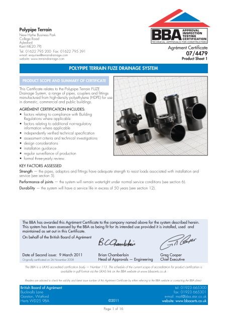
<strong>Polypipe</strong> <strong>Terrain</strong>New Hythe Business ParkCollege RoadAylesfordKent ME20 7PJTel: 01622 795 200 Fax: 01622 795 391e-mail: enquiries@terraindrainage.comwebsite: www.terraindrainage.comAPPROVALINSPECTIONTESTINGCERTIFICATIONTECHNICAL APPROVALS FOR CONSTRUCTIONAgrément Certificate07/4479Product Sheet 1<strong>POLYPIPE</strong> <strong>TERRAIN</strong> <strong>FUZE</strong> <strong>DRAINAGE</strong> <strong>SYSTEM</strong>PRODUCT SCOPE AND SUMMARY OF CERTIFICATEThis Certificate relates to the <strong>Polypipe</strong> <strong>Terrain</strong> <strong>FUZE</strong>Drainage System, a range of pipes, couplers and fittingsmanufactured from high-density polyethylene (HDPE) for usein domestic, commercial and public buildings.AGRÉMENT CERTIFICATION INCLUDES:• factors relating to compliance with BuildingRegulations where applicable• factors relating to additional non-regulatoryinformation where applicable• independently verified technical specification• assessment criteria and technical investigations• design considerations• installation guidance• regular surveillance of production• formal three-yearly review.KEY FACTORS ASSESSEDStrength — the pipes, adaptors and fittings have adequate strength to resist loads associated with installation andservice (see section 5).Performance of joints — the system will remain watertight under normal service conditions (see section 6).Durability — the system will have a service life in excess of 50 years (see section 12).The BBA has awarded this Agrément Certificate to the company named above for the system described herein.This system has been assessed by the BBA as being fit for its intended use provided it is installed, used andmaintained as set out in this Certificate.On behalf of the British Board of AgrémentDate of Second issue: 9 March 2011 Brian Chamberlain Greg CooperOriginally certificated on 26 November 2008 Head of Approvals — Engineering Chief ExecutiveThe BBA is a UKAS accredited certification body — Number 113. The schedule of the current scope of accreditation for product certification isavailable in pdf format via the UKAS link on the BBA website at www.bbacerts.co.ukReaders are advised to check the validity and latest issue number of this Agrément Certificate by either referring to the BBA website or contacting the BBA direct.British Board of Agrément tel: 01923 665300Bucknalls Lane fax: 01923 665301Garston, Watforde-mail: mail@bba.star.co.ukHerts WD25 9BA©2011website: www.bbacerts.co.ukPage 1 of 16
RegulationsIn the opinion of the BBA, the <strong>Polypipe</strong> <strong>Terrain</strong> <strong>FUZE</strong> Drainage System, if used in accordance with the provisions ofthis Certificate, will meet or contribute to meeting the relevant requirements of the following Building Regulations:The Building Regulations 2010 (England and Wales)Requirement: H1 Foul water drainageComment:The system will convey the flow of foul water and minimise the risk of blockage or leakage. See sections3.1 to 3.7, 5.1 and 5.2, 6.1 and 6.2, 7.1 and 7.2 and 9 of this Certificate.Requirement: H3(1) Rainwater drainageComment:The system will convey the flow of foul water and minimise the risk of blockage or leakage. See sections3.1 to 3.7, 5.1 and 5.2, 6.1 and 6.2, 7.1 and 7.2, 8.1 and 8.2 and 9 of this Certificate.Requirement: Regulation 7 Materials and workmanshipComment:The system is acceptable. See section 12 and the Installation part of this Certificate.The Building (Scotland) Regulations 2004 (as amended)Regulation: 8(1)(2) Fitness and durability of materials and workmanshipComment:The use of the system satisfies the requirements of this Regulation. See sections 11 and 12 and theInstallation part of this Certificate.Regulation: 9 Building standards — constructionStandard: 3.6(a) Surface water drainageComment:The system will satisfy the relevant requirements of this Standard, with reference to clause 3.6.1 (1)(2) . Seesections 3.1 to 3.7, 8.1 and 8.2 and 11 of this Certificate.Standard: 3.7(b)(c) Wastewater drainageComment:The system will satisfy the relevant requirements of this Standard, with reference to clause 3.7.1 (1)(2) . Seesections 8.1 and 8.2, 9 and 11 of this Certificate.Standard: 3.10 PrecipitationComment:The system satisfies the relevant requirements of this Standard, with reference to clauses 3.10.1 (1)(2) and3.10.6 (1)(2) . See sections 6.1 and 6.2 of this Certificate.(1) Technical Handbook (Domestic).(2) Technical Handbook (Non-Domestic).The Building Regulations (Northern Ireland) 2000 (as amended)Regulation: B2 Fitness of materials and workmanshipComment:The system is acceptable. See section 12 and the Installation part of this Certificate.Regulation: B3(2) Suitability of certain materialsComment:The system is acceptable. See section 11 of this Certificate.Regulation: C4 Resistance to ground moisture and weatherComment:The system meets the relevant requirements of this Regulation. See sections 6.1 and 6.2 of thisCertificate.Regulation: N3 Sanitary pipeworkComment:The system meets the relevant requirements of this Regulation. See sections 3.1 to 3.7 of this Certificate.Regulation: N5 Rain-water drainageComment: The system meets the relevant requirements of this Regulation. See sections 3.1 to 3.7, 8.1 and 8.2, 9and 11 of this Certificate.Construction (Design and Management) Regulations 2007Construction (Design and Management) Regulations (Northern Ireland) 2007Information in this Certificate may assist the client, CDM co-ordinator, designer and contractors to address theirobligations under these Regulations.See sections:3 General and 13 Installation of this Certificate.Non-regulatory InformationNHBC Standards 2011NHBC accepts the use of the <strong>Polypipe</strong> <strong>Terrain</strong> <strong>FUZE</strong> Drainage System, when installed and used in accordance withthis Certificate, in relation to NHBC Standards, Part 5 Substructure and ground floors, Chapter 5.3 Drainage belowground.Page 2 of 16
øGeneralThis Certificate relates to the <strong>Polypipe</strong> <strong>Terrain</strong> <strong>FUZE</strong> Drainage System.The system is for use in installations designed in accordance with BS EN 12056-2 : 2000 and/or BS EN 12056-3 :2000 for the conveyance of surface water and domestic sewage as is permitted to be discharged into public sewersby the Water Industry Act 1991 and surface water and sewage as is permitted and defined by the Sewerage(Scotland) Act 1968 and the Water and Sewerage Services (Northern Ireland) Order 1973.The system is for use in laboratory drainage where the chemical resistance of the HDPE is suitable for the envisagedeffluent. Guidance is given in CP 312-1 : 1973 on the chemical resistance of polyethylene pipework both at normaland elevated temperatures. The advice of the Certificate holder should be sought for resistance to chemicals notcovered by CP 312-1 : 1973.Components of the system can be used individually or in combination as described in this Certificate.This Certificate does not cover the use of any of the system for untreated trade effluents.Technical Specification1 Description1.1 <strong>Polypipe</strong> <strong>Terrain</strong> <strong>FUZE</strong> Drainage System pipes, couplers and fittings are manufactured from high-densitypolyethylene (HDPE) and comply with the recommendations of BS EN 1519-1 : 2000. They are black in colour andthe pipes are produced in 5 m (1) lengths.(1) 3 m and other suitable lengths are available by special order.1.2 The nominal outside diameters and wall thicknesses of pipes are given in Table 1.1.3 The dimensions of couplers and fittings are given in Tables 2 to 23. The types of couplers and fittings availableare:• bend 90° • bend 91° 30’ (88° 30’) • bend 45°• equal branch 45° • equal branch 88° 30’ • swept branch 88° 30’• double reducing Y branch 45° • expansion joint with cap • concentric reducers• screwed end cap • weld on end cap • end cap• access pipe with screw cap • electrofusion coupling • eccentric reducer• ball fitting double branch • ball fitting multi-branch • ventilation branch.Table 1HDPE soil and waste pipesPipe Outside Internal Wall Cross-sectional Nominal Weight Productlength diameter diameter thickness area pressure code(L) (m) (Ø) (mm) (Di) (mm) (S) (mm) (A) (cm 2 ) (PN) (bar) (kgm –1 )Soil pipes5 110 101.4 4.3 80.7 4 1.450 900.110.505 160 147.6 6.2 171.1 4 3.080 900.160.505 75 69 3 37.3 4.1 0.740 900.75.505 200 187.6 6.2 276.4 3.2 4.100 900.200.50Waste pipes5 40 34 3 9.0 8 0.370 900.40.505 50 44 3 15.2 6.4 0.460 900.50.505 56 50 3 19.6 5.7 0.530 900.56.50L 5000DiAall dimensions in mmSPage 3 of 16
ø øøTable 290° bendSL 2ROutside Wall Length Radius of Length of Weight Productdiameter thickness (L 1) (L 2) Bend straight code(Ø) (mm) (S) (mm) (mm) (mm) (R) (mm) (K) (mm) (kg)40 3 150 30 30 120 0.070 907.40.9050 3 180 40 40 140 0.095 907.50.9056 3 210 40 40 170 0.120 907.56.90RL 1KTable 391°30’ (88° 30’) bendOutside Wall Length Length of Weight Productdiameter thickness straight code(Ø) (mm) (S) (mm) (L) (mm) (K) (mm) (kg)Soil pipes110 4.3 95 25 0.230 901.110.92160 6.2 123 35 0.700 901.160.9275 3 75 20 0.095 901.75.92Waste pipes50 3 60 20 0.050 901.50.9256 3 65 20 0.060 901.56.92L88°30’LKSKTable 445° bendOutside Wall Length Length of Weight Productdiameter thickness straight code(Ø) (mm) (S) (mm) (L) (mm) (K) (mm) (kg)Soil pipes110 4.3 60 25 0.170 901.110.135160 6.2 69 20 0.430 901.160.13575 3 50 20 0.070 901.75.13545°LSWaste pipes40 3 45 20 0.030 901.40.13550 3 45 20 0.040 901.50.13556 3 45 20 0.045 901.56.135LøKKTable 545° equal branchOutside Wall Length Length of Length of Length of Length of Weight Productdiameter thickness (L) straight straight connection connection code(Ø/Ø 1) (S/S 1) (L 1) (equal branch) (K 1) (equal branch)(L 2/L 3) (K 2/K 3)(mm) (mm) (mm) (mm) (mm) (mm) (mm) (kg)Soil pipes110/110 4.3 270 90 180 55 20 0.530 904.110.135160/160 6.2 375 125 250 75 25 1.475 904.160.13575/75 3 210 70 140 40 25 0.205 904.75.135200/200 (1) 6.2 540 180 360 85 10 2.990 904.200.135Waste pipes40/40 3 135 45 90 25 30 0.070 904.40.13550/50 3 165 55 110 35 20 0.105 904.50.13556/56 3 180 60 120 40 25 0.130 904.56.135(1) Segmented.K 3L 3LL 145°SK 1øL 2ø 1S 1K 2Page 4 of 16
øøøøøTable 688° 30’ equal branchOutside Wall Length Length of Length of straight Length of Length of connection Weight Productdiameter thickness straight (equal branch) connection (equal branch) code(Ø/Ø 1) (S/S 1) (L) (L 1) (L 2/L 3) (K 1) (K 2/K 3)(mm) (mm) (mm) (mm) (mm) (mm) (mm) (kg)Soil pipes110/110 4.3 225 135 90 65 20 0.365 904.110.90160/160 6.2 350 210 140 105 30 1.190 904.160.9075/75 3 175 105 70 55 25 0.145 904.75.90200/200 (1) 6.2 360 180 180 25 30/25 1.705 904.200.90Waste pipes40/40 3 130 75 55 45 20 0.060 904.40.9050/50 3 150 90 60 55 25 0.085 904.50.9056/56 3 175 105 70 65 30 0.105 904.56.90LK 3L 3L 1K 188°30’ø 1S 1K 2L 2S(1) Welded.Table 7Soil pipes — 88° 30’ swept branchK 388°30’L 3Outside Wall Length Length of Length of straight Length of Length of connection Weight Productdiameter thickness straight (equal branch) connection (equal branch) code(Ø/Ø 1) (S/S 1) (L) (L 1) (L 2/L 3) (K 1) (K 2/K 3)(mm) (mm) (mm) (mm) (mm) (mm) (mm) (kg)LL 1ø 1S 1L 2K 2110/110 4.3 230 140 120/90 90 40/20 0.415 904.110.92SK 1Table 8Soil pipes — 45° double reducing Y branchOutside Wall Length Length of Length of straight Length of Length of connection Weight Productdiameter thickness straight (Y branches) connection (equal branch) code(Ø/Ø 1) (S/S 1) (L) (L 1) (L 2/L 3) (K 1) (K 2/K 3)(mm) (mm) (mm) (mm) (mm) (mm) (mm) (kg)110/110 4.3 270 90 180 50 15 0.630 906.110.135K 3ø 1L 3K 1L 2K 2S 1LL 145° 45°SDEDETable 9Expansion joint with capOutside Wall Cap Length Length of Length of Weight Productdiameter thickness diameter straight connection code(Ø) (mm) (S) (mm) (DE) (mm) (L) (mm) (L 1) (mm) (K) (mm) (kg)110 4.3 140 255 46 20 0.500 911.110160 6.2 192 260 72 40 1.010 911.160KL L30L 1L 1S 4420°0°max 6 mKSall dimensions in mmPage 5 of 16
øøTable 10 Concentric reducersOutside Wall Wall Length Length of Length of Weight Productdiameter thickness thickness straight connection code(Ø/Ø 1) (mm) (S) (mm) (S 1) (mm) (L) (mm) (L 1/L 2) (mm) (K) (mm) (kg)Soil pipes110/40 4.3 3 80 30 15 0.090 924.11040 K110/50 4.3 3 80 30 15 0.115 924.11050110/56 4.3 3 80 30 15 0.095 924.11056110/75 4.3 3 80 30 15 0.125 924.11075 KWaste pipes50/40 3 3 80 30 15 0.040 924.504056/50 3 3 80 30 15 0.040 924.5650 øS 1L 2LL 1Sø 1øDETable 11 Soil pipes — screwed end capL 2Outside Wall Length Length of Length of Length of Screw cap Weight Productdiameter thickness connection screw fitting pipe diameter code(Ø) (mm) (S) (mm) (L) (mm) (L 1) (mm) (L 2) (mm) (L 3) (mm) (DE) (mm) (kg)110 4.3 106 30 65 89 144 0.500 936.110SL 1L L 3Table 12 Weld-on end capOutside Wall Length Weight Productdiameter thickness code(Ø) (mm) (S) (mm) (L) (mm) (kg)Soil pipes110 4.3 10 0.050 930.11075 3 10 0.020 930.7590 3.5 10 0.030 930.90Waste pipes40 3 10 0.010 930.4050 3 10 0.010 930.5056 3 10 0.010 930.56LSTable 13 Soil pipes — end capOutside Wall Length Weight Productdiameter thickness code(Ø) (mm) (S) (mm) (L) (mm) (kg)160 6.2 72 0.310 930.160LSPage 6 of 16
øøTable 14 Soil pipes — access pipe with screw capOutside Wall Length Longest length Shortest length Height from Screw Length Length Weight Productdiameter thickness to centre to centre centre to top cap of longest of shortest codeof cap of cap of screw cap diameter connection connection(Ø) (mm) (S) (mm) (L) (mm) (L 1) (mm) (L 2) (mm) (H) (mm) (DE) (mm) (K 1) (mm) (K 2) (mm) (kg)110 4.3 240 140 100 94 146 65 20 0.620 938.110.90160 6.2 350 210 140 145 146 105 30 1.355 938.160.90DEHK 1 K 2SL 1LL 2Table 15 Electrofusion couplingsInside Length Height Overall Thickness of Weight Productdiameter height centre stop code(Ø) (mm) (L) (mm) (DE) (mm) (H) (mm) (H 1) (mm) (kg)Soil pipes110 60 126 143 3 0.165 910.110160 60 178 194 3 0.260 910.16075 60 90 105 3 0.105 910.75200 153 233 248 3 1.705 910.200Waste pipes40 64 52 68 3 0.055 910.4050 60 63 80 3 0.070 910.5056 60 70 86 3 0.085 910.56HDELH 1Table 16 Eccentric reducersOutside Offset wall Straight wall Length Length of Weight Productdiameter thickness thickness straight code(Ø/Ø 1) (mm) (S) (mm) (S 1) (mm) (L) (mm) (L 1/L 2) (mm) (kg)Soil pipes110/40 4.3 3 80 37/35 0.095 923.11040110/50 4.3 3 80 37/35 0.100 923.11050110/56 4.3 3 80 37/35 0.100 923.11056110/75 4.3 3 80 37/35 0.105 923.11075160/110 6.2 4.3 80 37/35 0.230 923.160110Waste pipes50/40 3 3 80 35 0.035 923.504056/50 3 3 80 37/35 0.040 923.5650S 1ø 1øL 1L 2SLPage 7 of 16
Table 17 Soil pipes — 180° double branch ball fittingOutside Wall Wall Height Overall Length to Length to Length of Length of Weight Productdiameter thickness thickness diameter centre centre of connection connection codebranchof branch(Ø/Ø 1) (mm) (S) (mm) (S 1) (mm) (H) (mm) (DE) (mm) (L 1/L 3) (mm) (L 2) (mm) (K 1/K 3) (mm) (K 2) (mm) (kg)110/50 4.3 3 220 170 105 120 15 15 0.440 916.11050.180110/56 4.3 3 220 170 105 120 15 15 0.450 916.11056.180110/75 4.3 3 220 170 105 120 15 15 0.430 916.11075.180110/90 4.3 3.5 220 170 105 120 15 15 0.470 916.11090.180110/110 4.3 4.3 220 170 105 120 15 15 0.480 916.110.180125/50 4.9 3 220 190 110 125 15 15 0.495 916.12550.180125/56 4.9 3 220 190 110 125 15 15 0.500 916.12556.180125/75 4.9 3 220 190 110 125 15 15 0.555 916.12575.180125/90 4.9 3.5 220 190 110 125 15 15 0.555 916.12590.180125/110 4.9 4.3 220 190 110 125 15 25 0.565 916.125110.180125/125 4.9 4.9 220 190 110 125 15 25 0.625 916.125.18088°30’ø88°30’SL 3HL 1K 3180°S 1ø 1K 2L 2K 1SøL 3K 3DE88°30’DEHL 1S 1ø 1K 2L 2K 190°Table 18 Soil pipes — 90° double branch ball fittingOutside Wall Wall Height Overall Length to Length to Length of Length of Weight Productdiameter thickness thickness diameter centre centre of connection connection codebranchof branch(Ø/Ø 1) (mm) (S) (mm) (S 1) (mm) (H) (mm) (DE) (mm) (L 1/L 3) (mm) (L 2) (mm) (K 1/K 3) (mm) (K 2) (mm) (kg)110/50 4.3 3 220 170 105 120 15 15 0.450 916.11050.90110/56 4.3 3 220 170 105 120 15 15 0.425 916.11056.90110/75 4.3 3 220 170 105 120 15 15 0.500 916.11075.90110/90 4.3 3.5 220 170 105 120 15 15 0.465 916.11090.90110/110 4.3 4.3 220 170 105 120 15 15 0.505 916.110.90125/50 4.9 3 220 190 110 125 15 15 0.500 916.12550.90125/56 4.9 3 220 190 110 125 15 15 0.500 916.12556.90125/75 4.9 3 220 190 110 125 15 15 0.530 916.12575.90125/90 4.9 3.5 220 190 110 125 15 15 0.540 916.12590.90125/110 4.9 4.3 220 190 110 125 15 25 0.605 916.125110.90125/125 4.9 4.9 220 190 110 125 15 25 0.620 916.125.90Page 8 of 16
Table 19 Soil pipes — 135° double branch ball fittingOutside Wall Wall Height Length to Length to Length of Length of Weight Productdiameter thickness thickness centre centre of connection connection codebranchof branch(Ø/Ø 1) (mm) (S) (mm) (S 1) (mm) (H) (mm) (L 1/L 3) (mm) (L 2) (mm) (K 1/K 3) (mm) (K 2) (mm) (kg)110/50 4.3 3 220 105 120 15 15 0.440 916.11050.135110/56 4.3 3 220 105 120 15 15 0.445 916.11056.135110/75 4.3 3 220 105 120 15 15 0.455 916.11075.135110/90 4.3 3.5 220 105 120 15 15 0.470 916.11090.135110/110 4.3 4.3 220 105 120 15 25 0.500 916.110.135125/50 4.9 3 220 110 125 15 15 0.490 916.12550.135125/56 4.9 3 220 110 125 15 15 0.555 916.12556.135125/75 4.9 3 220 110 125 15 15 0.565 916.12575.135125/90 4.9 3.5 220 110 125 15 15 0.575 916.12590.135125/110 4.9 4.3 220 110 125 15 25 0.600 916.125110.135125/125 4.9 4.9 220 110 125 15 25 0.740 916.125.13588°30’øS88°30’L 3HK 3L 2135°L 1K 2K 188°30’ø88°30’SS 1S 1L 3ø 190°HL 1K 3K 2K 1L 2ø 190° 90°Table 20 Soil pipes — 90° multi-branch ball fittingOutside Wall Wall Height Length to Length to Length of Length of Weight Productdiameter thickness thickness centre centre of connection connection codebranchof branch(Ø/Ø 1) (mm) (S) (mm) (S 1) (mm) (H) (mm) (L 1/L 3) (mm) (L 2) (mm) (K 1/K 3) (mm) (K 2) (mm) (kg)110/50 4.3 3 220 105 120 15 15 0.320 916.11050.903110/56 4.3 3 220 105 120 15 15 0.470 916.11056.903110/75 4.3 3 220 105 120 15 15 0.460 916.11075.903110/90 4.3 3.5 220 105 120 15 15 0.510 916.11090.903110/110 4.3 4.3 220 105 120 15 15 0.545 916.110.903125/50 4.9 3 220 110 125 15 15 0.570 916.12550.903125/56 4.9 3 220 110 125 15 15 0.515 916.12556.903125/75 4.9 3 220 110 125 15 15 0.515 916.12575.903125/90 4.9 3.5 220 110 125 15 15 0.525 916.12590.903125/110 4.9 4.3 220 110 125 15 25 0.595 916.125110.903125/125 4.9 4.9 220 110 125 15 25 0.670 916.125.903Page 9 of 16
Table 21 Soil pipes — 135° multi-branch ball fittingOutside Wall Wall Height Length to Length to Length of Length of Weight Productdiameter thickness thickness centre centre of connection connection codebranchof branch(Ø/Ø 1) (mm) (S) (mm) (S 1) (mm) (H) (mm) (L 1/L 3) (mm) (L 2) (mm) (K 1/K 3) (mm) (K 2) (mm) (kg)110/50 4.3 3 220 105 120 15 15 0.465 916.11050.1353110/56 4.3 3 220 105 120 15 15 0.455 916.11056.1353110/75 4.3 3 220 105 120 15 15 0.440 916.11075.1353110/90 4.3 3.5 220 105 120 15 15 0.450 916.11090.1353110/110 4.3 4.3 220 105 120 15 15 0.540 916.110.1353125/50 4.9 3 220 110 125 15 15 0.630 916.12550.1353125/56 4.9 3 220 110 125 15 15 0.515 916.12556.1353125/75 4.9 3 220 110 125 15 15 0.620 916.12575.1353125/90 4.9 3.5 220 110 125 15 15 0.630 916.12590.1353125/110 4.9 4.3 220 110 125 15 25 0.620 916.125110.1353125/125 4.9 4.9 220 110 125 15 25 0.670 916.125.135388°30’øS88°30’L 3HK 3L 2135°L 1K 2K 188°30’øS88°30’S 1L 3ø 1S 190°K 3Hø 1L 1K 2L 2K 190° 90°Table 22 Soil pipes — multi-branch ball fittingOutside Wall Wall Height Length to Length to Length of Length of Weight Productdiameter thickness thickness centre centre of connection connection codebranchof branch(Ø/Ø 1) (mm) (S) (mm) (S 1) (mm) (H) (mm) (L 1/L 3) (mm) (L 2) (mm) (K 1/K 3) (mm) (K 2) (mm) (kg)110/50 4.3 3 220 105 120 15 15 0.480 916.11050.904110/56 4.3 3 220 105 120 15 15 0.480 916.11056.904110/75 4.3 3 220 105 120 15 15 0.475 916.11075.904110/90 4.3 3.5 220 105 120 15 15 0.535 916.11090.904110/110 4.3 4.3 220 105 120 15 15 0.575 916.110.904125/50 4.9 3 220 105 125 15 15 0.530 916.12550.904125/56 4.9 3 220 105 125 15 15 0.485 916.12556.904125/75 4.9 3 220 105 125 15 15 0.425 916.12575.904125/90 4.9 3.5 220 105 125 15 15 0.680 916.12590.904125/110 4.9 4.3 220 105 125 15 25 0.690 916.125110.904125/125 4.9 4.3 220 105 125 15 25 0.740 916.125.904Page 10 of 16
Table 23 Soil pipes — ventilation branchOutside Large Small Width Width Width Width Overall Height Height Height Height Weight Productdiameter crosspipe crosspipe to centre from centre from centre width of to centre across to centre codediameter diameter of straight straight to of ventilation straight of small centres of of largecentre ofcrosspipe crosspipes crosspipeVentilation(Ø) (Ø 1Ø 2Ø 3)(Ø 4Ø 5Ø 6) (L) (L 1) (L 2) (L 3) (L 4) (H) (H 1) (H 2) (H 3)(mm) (mm) (mm) (mm) (mm) (mm) (mm) (mm) (mm) (mm) (mm) (mm) (kg)110 110 max 75 max 275 90 130 55 188 700 230 170 300 2.570 908.110160 110 max 75 max 310 90 160 60 190 1010 460 170 380 5.000 908.160LL 1L 2L 3L 4H 3ø 2 ø 3ø 1ø 6HH 2ø4ø 5H 1ø1.4 There are six methods available from <strong>Polypipe</strong> <strong>Terrain</strong> for joining the pipe and fittings (1) (see Figure 1):• butt welding • screw-threaded joint • electrofusion coupling• expansion socket • ring seal socket • flange joint.(1) The <strong>Polypipe</strong> <strong>Terrain</strong> <strong>FUZE</strong> Jointing Methods brochure gives full details of each.1.5 The HDPE pipes are extruded from batch-mixed raw materials and cut to length, and the fittings are injectionmoulded or welded extrusions.1.6 Continuous quality control is exercised during manufacture to maintain quality. The checks include:Pipes• appearance • dimensional accuracy • pressure• melt-flow index• heat reversion.Fittings• appearance• dimensional accuracy• appearance and dimensional stability after heating to 60°C – 110°C • melt-flow index.1.7 A label bearing the BBA identification mark incorporating the number of this Certificate is attached to each pipelength and fitting or to each crate of pipes or box of fittings.2 Delivery and site handling2.1 Pipes are supplied in lightweight, reinforced brackets and should be stored on a flat surface in stacks not morethan 1.7 m high and away from heat sources, to avoid distortion.2.2 The pipes are marked with:• material HDPE • outside diameter and wall thickness • BS EN 1519-1 : 2000• manufacturer’s mark.2.3 The fittings are supplied in boxes which are marked with the associated outside diameter and reference code.Page 11 of 16
Figure 1<strong>Polypipe</strong> <strong>Terrain</strong> <strong>FUZE</strong> jointing methodsbutt weldscrew-threaded couplingelectrofusion couplingexpansion socketring-seal socketflange jointAssessment and Technical InvestigationsThe following is a summary of the assessment and technical investigations carried out on the <strong>Polypipe</strong> <strong>Terrain</strong> <strong>FUZE</strong>Drainage System.Design Considerations3 General3.1 <strong>Polypipe</strong> <strong>Terrain</strong> <strong>FUZE</strong> Drainage System pipes and fittings are satisfactory for use in domestic, commercialand public buildings and in installations designed in accordance with BS EN 12056-2 : 2000 andBS EN 12056-3 : 2000 for the conveyance of surface water and domestic sewage as is permitted to bedischarged into public sewers by the Public Health Act 1936 (England and Wales), and surface water and sewage asis permitted and defined by the Sewerage (Scotland) Act 1968 and the Water and Sewerage Services (NorthernIreland) Order 1973.3.2 The average linear expansion coefficient for <strong>Polypipe</strong> <strong>Terrain</strong> <strong>FUZE</strong> Drainage pipes is 2 x 10 –4 m·m –1·°C.Installations must be designed to accommodate or prevent the anticipated thermal movement as follows:Prevention of longitudinal thermal movement3.3 Movement can be prevented by embedding the pipe (with electroweld sleeves or bushes) in concrete or by rigidfixings.Embedment3.4 The adhesion between concrete and pipe is inadequate to prevent movement. When installed within concretefloors the movement is prevented by the use of electroweld sleeves or bushes which protrude from the external surfaceof the pipe. These fittings must be used near each branch connection. Ring-seal sockets should not be embedded inconcrete. The expansion and contraction forces created by thermal movement must be accommodated by the concrete.Page 12 of 16
Rigid installation3.5 The forces exerted on pipe supports, anchors and the structure must be considered when this approach is used.Rigid fixings are not considered suitable for pipes over 160 mm in diameter. Guidance on the load exerted on fixingsis available from the manufacturer.Accounting for length/longitudinal movement3.6 Vertical and horizontal expansion can be catered for by the expansion socket. The product is designed to copewith the expansion equivalent to a 5 m run of pipe through a temperature change of 80°C. This product should beused in conjunction with rigid anchor fixings and sliding guide hangers. Sliding guide hangers are not provided as partof the system, but are available as proprietary products.3.7 Thermal movement can also be accommodated by the incorporation of a deflection leg within the design of theinstallation of the system. The maximum anticipated movement is determined, and the length of the required deflectionleg appropriate to the predicted movement. Sliding supports allow the pipe expansion to occur between two fixedsupports in the structure.4 Practicability of installationInstallation of the pipes and fittings is achieved easily providing the procedures detailed in the <strong>Polypipe</strong> <strong>Terrain</strong> <strong>FUZE</strong>Drainage brochure are strictly adhered to (see also section 14 of this Certificate).5 Strength5.1 <strong>Polypipe</strong> <strong>Terrain</strong> <strong>FUZE</strong> pipes and fittings will have adequate resistance to the types of loading associatedwith installation and normal service conditions.5.2 The system should be protected from impacts, for example from heavy vehicles such as fork-lift trucks used oncommercial premises.6 Performance of joints6.1 The joints will not be adversely affected by thermal movement provided the correct provision is made.6.2 The joints will remain watertight under conditions of pipeline movement in excess of those expected to occur innormal good drainage practice.7 Flow characteristics7.1 A system incorporating <strong>Polypipe</strong> <strong>Terrain</strong> <strong>FUZE</strong> pipes and fittings will have satisfactory flow characteristics.Primary ventilated stack systems to BS EN 12056-2 : 2000, clause 4.3.1 and Table 1, are restricted inaccordance with clause 6.5.1 and Table 11. For flow capacity calculations, ball fittings should be consideredas having square entries.7.2 Use of ventilation branches in a stack allows the design capacity of a 110 mm primary ventilated stack to beincreased to 8.7 l·s –1 maximum, and the 160 mm diameter to 18.1 l·s –1 maximum, thus avoiding the need foradditional ventilation (see Table 24). The stack design must be in accordance with the Certificate holder’s guidelines(see Figure 2). A ventilation branch fitting must be installed at each floor above the ground floor, even if appliances arenot connected. The ground pipe must be 160 mm in diameter and a pressure relief line must be installed at the bend atthe bottom of the stack.Table 24 Maximum flow rates of waste in the stacks with ventilation branchesStack diameter Total flow dischargable Maximum project flow Maximum number of connectableDN De in the stack in the stack equivalent apartments(mm) (mm) ( DU) (l·s –1 ) (Q ww) (l·s –1 )100 110 303 8.7 45150 160 1310 18.1 195Page 13 of 16
Figure 2Waste system with ventilation branchesventilation branchstandard branchvent loop8 Resistance to chemicals8.1 The system will be unaffected by those types and quantities of chemicals likely to be found in the effluentsdefined in section 3.1 of this Certificate.8.2 Details of the chemical resistance of HDPE are given in CP 312-1 : 1973.9 Resistance to elevated temperaturesThe system has adequate resistance to the temperatures likely to occur in the effluents defined in section 3.1 ofthis Certificate.10 Behaviour in relation to fire10.1 In common with other plastics materials, <strong>Polypipe</strong> <strong>Terrain</strong> <strong>FUZE</strong> pipes and fittings are combustible and in a firemay ignite and burn. The pipes, adaptors and fittings are high-density polyethylene and their burning will not result inthe release of toxic gases. However, consideration should be given to the need for protective, fire-resistant ductingwhen assessing the fire risk in a building, particularly where large quantities of piping may otherwise be exposed.10.2 In England and Wales the detailed requirements are given in Approved Document B.Page 14 of 16
10.3 In Scotland and Northern Ireland, pipes which penetrate separating or compartment walls or floors must beconstructed or protected so that, in the event of fire, the fire resistance required for the wall or floor is maintained, andthey must be fire-stopped.11 MaintenanceSections of the system can easily be removed and replaced. The installation must be designed so that access isprovided in accordance with BS EN 12056-2 : 2000, clause ND4.12 DurabilityIn the opinion of the BBA, when used in the context of this Product Sheet, the materials from which thecomponent parts of the pipes, adaptors and fittings are manufactured will not significantly deteriorate and thesystem will have serviceable life equivalent to PVC-U sanitary pipework systems.Installation13 Procedure13.1 Installation must be in accordance with the manufacturer’s literature and the recommendations given inBS EN 12056-2 : 2000 and BS EN 12056--3 : 2000 where appropriate.13.2 End-to-end butt weld joints must be carried out under controlled conditions as follows:• pipe must be cut square and clean using a <strong>Polypipe</strong> <strong>Terrain</strong> pipe cutter• the welding plate must be clean• the required lateral pressure must be applied• appropriate heat-up and weld time should be used.13.3 Welding procedure is as follows:• the face of each item is heated by lightly pressing the components against the heating plate for the correct period• clamping pressure is gradually increased to the required value and held for the specified period• clamps and jigs are available to ensure correct alignment of the joint.13.4 Electroweld joints using the appropriate <strong>Polypipe</strong> <strong>Terrain</strong> welder must be carried out as follows:• the pipe end and sleeve must be kept dry at all times• the pipe is cut off at right-angles, deburred and cleaned• the pipe or fitting is inserted into the sleeve to the central register, the welder is connected to the sleeve andoperated in accordance with the manufacturer’s instructions.13.5 Other types of connection sleeve must be butt welded to the spigot to be joined in accordance with sections13.2 and 13.3. The connection is made according to the joint type as follows:• ring-seal socket — the pipe or fitting spigot is lubricated and pushed fully into the socket• expansion socket (1) — the pipe is pushed the appropriate length into the socket, depending on the temperature atthe time of installation (see Table 9)• screw-threaded fittings are connected to spigots by inserting the spigot fully into the joint and tightening the lockingcollar by hand.(1) Expansion sockets should be protected from the ingress of dirt.13.6 Pipes are secured by anchor brackets on hangers (not covered by this Certificate). The maximum spacing of thesupports must be ten times the pipe diameter for vertical and horizontal pipes.Technical Investigations14 Investigations14.1 An examination was made of data relating to:• material properties • dimensions in relation to BS EN 1519-1 : 2000 • installation• thermal shock • heat reversion • melt-flow index• resistance to pressure.14.2 The manufacturing process was examined, including the methods adopted for quality control, and details wereobtained of the quality and composition of the materials used.Page 15 of 16
BibliographyBS EN 1519-1 : 2000 Plastics piping systems for soil and waste discharge (low and high temperature) within thebuilding structure. Polyethylene (PE) — Specifications for pipes, fittings and the systemBS EN 12056-2 : 2000 Gravity Drainage Systems inside Buildings — Sanitary pipework, layout and calculationBS EN 12056-3 : 2000 Gravity Drainage Systems inside Buildings — Roof drainage, layout and calculationCP 312-1 : 1973 Code of practice for plastics pipework (thermoplastics material) — General principles and choice ofmaterialConditions of Certification15 Conditions15.1 This Certificate:• relates only to the product/system that is named and described on the front page• is granted only to the company, firm or person named on the front page — no other company, firm or person mayhold or claim any entitlement to this Certificate• is valid only within the UK• has to be read, considered and used as a whole document — it may be misleading and will be incomplete to beselective• is copyright of the BBA• is subject to English law.15.2 References in this Certificate to any Act of Parliament, Statutory Instrument, Directive or Regulation of theEuropean Union, British, European or International Standard, Code of Practice, manufacturers’ instructions or similarpublication, are references to such publication in the form in which it was current at the date of this Certificate.15.3 This Certificate will remain valid for an unlimited period provided that the product/system and the manufactureand/or fabrication including all related and relevant processes thereof:• are maintained at or above the levels which have been assessed and found to be satisfactory by the BBA• continue to be checked as and when deemed appropriate by the BBA under arrangements that it will determine• are reviewed by the BBA as and when it considers appropriate.15.4 In granting this Certificate, the BBA is not responsible for:• the presence or absence of any patent, intellectual property or similar rights subsisting in the product/system or anyother product/system• the right of the Certificate holder to manufacture, supply, install, maintain or market the product/system• individual installations of the product/system, including the nature, design, methods and workmanship of or relatedto the installation• the actual works in which the product/system is installed, used and maintained, including the nature, design,methods and workmanship of such works.15.5 Any information relating to the manufacture, supply, installation, use and maintenance of this product/systemwhich is contained or referred to in this Certificate is the minimum required to be met when the product/system ismanufactured, supplied, installed, used and maintained. It does not purport in any way to restate the requirements ofthe Health & Safety at Work etc Act 1974, or of any other statutory, common law or other duty which may exist at thedate of this Certificate; nor is conformity with such information to be taken as satisfying the requirements of the 1974Act or of any statutory, common law or other duty of care. In granting this Certificate, the BBA does not acceptresponsibility to any person or body for any loss or damage, including personal injury, arising as a direct or indirectresult of the manufacture, supply, installation, use and maintenance of this product/system.British Board of Agrément tel: 01923 665300Bucknalls Lane fax: 01923 665301Garston, Watforde-mail: mail@bba.star.co.ukHerts WD25 9BA©2011website: www.bbacerts.co.ukPage 16 of 16