Indeeco Open Coil Duct Heaters - Heaters Sensors Controls
Indeeco Open Coil Duct Heaters - Heaters Sensors Controls
Indeeco Open Coil Duct Heaters - Heaters Sensors Controls

Create successful ePaper yourself
Turn your PDF publications into a flip-book with our unique Google optimized e-Paper software.
Standard <strong>Duct</strong> <strong>Heaters</strong><strong>Open</strong> <strong>Coil</strong>Detail DimensionsThe wide variety of QUA and QUZ (Figures 47and 48) heaters makes it impractical to list the exactheater dimensions for every possible heater. Fordimensional details, contact your local INDEECOrepresentative.Voltage and Phase<strong>Heaters</strong> are available in the voltage and phasecombinations shown below. All are for operation at50 or 60 Hz.When three-phase is specified, each heating stagewill be furnished with a multiple of three elements togive a balanced three-phase load.Control Circuit Options & SpecialFeaturesQUA and QUZ heaters are available with ControlOptions G, J and K and a full range of SpecialFeatures. These are described briefly in Table VIIIand in more detail in the standard Control Optionssection of this catalog, pages 10 and 11.Number of Heating StagesSingle and three-phase QUA and QUZ heaters areavailable with multiple heating stages. To complywith our UL and NEC maximum circuit sizes, nostage is rated at more than 48 amps.Voltage 120 208 240 277 208 240 380 400 415 480 600Phase 1 3Table VIIIControl OptionsControlOptionGBasicJPneumaticKProportionalDisconnectSwitchThermalCutoutsAirflowSwitchContactorsControlTransformerFuses• • • • • •Notes: 1. Fuses supplied only on heaters over 48 amps.2. Contactors supplied only when other devices cannot carry heater load.3. Transformer only supplied on heaters rated higher than 277 volts.4. Choice of room or duct thermostat, 135 ohms, 2200 ohms, 0-10 VDC or 4-20 mA inputs.See pages 12 and 13 for full description of thermostats.PESwitches• • • • • • •22SCRThermostat• • • • • • • •3111 4Star Electric to Order Call 1.800.345.0369
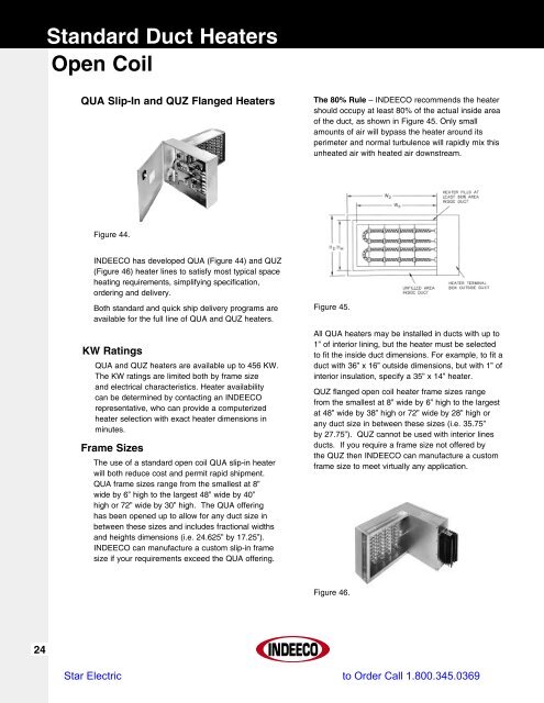
Standard <strong>Duct</strong> <strong>Heaters</strong><strong>Open</strong> <strong>Coil</strong>Special FeaturesWhile QUA slip-in and QUZ flanged heaters maybe specified with one of the standard control circuitoptions, individual job requirements may demandslight variations from the standards. The mostcommon variations are covered by INDEECO’sset of Special Features which may be used toTable IXmodify QUA/QUZ heaters both mechanically andelectrically. These are listed in Table IX with a briefdescription, availability, and notes on any limitationsof their use.Table X provides a summary of thermostats offeredwith INDEECO QUA/QUZ heaters. See pages 12and 13 for more detailed descriptions.Special FeaturesSpecialFeatureCodeDescriptionPageRef.Availability& LimitationsMechanicalHorizontal AirflowU8Allows heater to be used in applicationswhere airflow is either right(U4) or left (U6)23 Available on all heaters.Vertical AirflowU9Allows heater to be used in applicationswhere airflow is either verticalup (U3) or vertical down (U5.)23 Available on all heaters.Pressure PlateV140% open perforated plate installedonto the inlet side of the heaterframe to help even out irregularairflow patterns.35Available on all heaters.Exact airflow direction mustbe specified U3, U4, U5 orU6.Protective ScreenV/V2Wire mesh screen for attachment tothe heater frame. Can be furnishedfor one or both sides.36Available on all heaters.Screens are shipped loosefor field installation.Stainless Steel Frame andTerminal BoxH2Heater frame and terminal box constructedof 304 stainless steel.Available on all heaters.Aluminized Steel Frameand Terminal BoxH1Heater frame and terminal box constructedof aluminized steel.Available on all heaters.Insulated <strong>Duct</strong> Constructionfor Slip-in <strong>Heaters</strong>GG2Used in ducts lined with more than1” thick interior insulation. Insideduct dimensions and insulationthickness must be specified. Maximum6” thick lining.36Available with QUA heatersonly.Unheated SectionsG2Extended terminal pins to providean unheated section adjacent tothe heater terminal box. Maximumextended terminal pin length of 6”.36 Available on all heaters.Substitute NegativePressure SwitchQ5/Q6Allows heater to be used on inletside of fan.15 Available on all heaters.27Star Electric to Order Call 1.800.345.0369
Standard <strong>Duct</strong> <strong>Heaters</strong><strong>Open</strong> <strong>Coil</strong>Table IX (continued)Special FeaturesSpecialFeatureCodeDescriptionPageRef.Availability& LimitationsMechanical (cont.)Right/Down TerminalBox OverhangL4/L5Heater will be supplied with terminalbox overhang on right (if horizontalairflow installation) or downward (ifvertical airflow installation).23 Available on all heaters.Insulated Terminal BoxB2Prevents condensation inside terminalbox when heater is installed inair conditioning duct running throughun-airconditioned area.35 Available on all heaters.Dust-Tight Terminal BoxB7Allows installation in dusty areasand satisfies local codes requiringdust-tight box, if installed in areaused as return air plenum.34 Available on all heaters.Remote PanelboardB5All controls except thermal cutouts,airflow switch and pilot switch willbe supplied in a separate NEMA 1panelboard.37Available on all heaters exceptwhen transformer andcontactors are deleted.ElectricalAdd “Stage On”Pilot Light(s)Add “Low Airflow”and “Heater On”Pilot LightsFan RelayAdd INDEECOElectronicStep ControllerLow Watt Density <strong>Coil</strong>sAdd Built-in PETransducerTransformer PrimaryFusingP1P2, P3N(000)SD3, D4To indicate when each heating stageis producing heat.Separate pilot lights to indicate thatpower has been supplied to theheater, that it is ready for operation,and whether airflow has been interrupted.When static pressure in the duct istoo low (below .07” WC) to operatethe airflow switch or when airflowswitch is not desired. (000) denotesholding coil 24, 120, 208, 240, or277 volts.Allows better temperature control ofhigh capacity heater by using multiplestages controlled by electronicthermostat and step controller.To meet specifications which call forlow watt density coils.17171519-20E32, S19 To allow for pneumatic control. 13T1 Add transformer primary fusing.Available on all heaters exceptOption K SCR stages.Available on all heaters.When fan relay has beensubstituted for airflowswitch, only “Heater On”will be supplied.Available on Option G & Kheaters except Option Gheaters where deletion ofcontactors and transformersis specified.Only available on OptionG heaters with 2 or moreheating stages.Available on all heaters.Available on Option K heatersor Option G heaterswith step controller and 5 ormore stages.Available with all heaterswith built-in transformer.28Star Electric to Order Call 1.800.345.0369
Standard <strong>Duct</strong> <strong>Heaters</strong><strong>Open</strong> <strong>Coil</strong>Table IX (continued)Special FeaturesSpecialFeatureCodeDescriptionPageRef.Availability& LimitationsElectrical (cont.)Delete TransformerDelete Transformer& ContactorsAllows control circuit to be obtainedfrom source outside the heater or,when line voltage is equal to controlvoltage, directly from power lineswithin the heater.Allows for control of heater directlyusing load carrying thermostats.1616Only available on Option Gheaters. Must be specifiedif control voltage is not 120or 24 volts. Customer mustspecify control volts.Available only on singlestage, single-phase, OptionG heaters with KW notexceeding the following.Voltage 120 277Max. KW 1.8 4.1TransformerSecondary FusingT3External fused and grounded transformersecondary for Class II 24 voltcontrol circuits.Available on all heaters.Additional UserControl CircuitVoltageHeater control circuit transformersized for additional user VA. Acontrol terminal block is furnished forfield connection.Available on all heaters.Consult factory for 1 weekor 72 hour heater availability.Delete DisconnectAllows for use of field installed disconnectingmeans. (Must be withinsight of the heater.)16 Available on all heaters.Fused DisconnectSwitchQ1Door interlocking disconnect withline fusing for heaters loads up to 48amps or less.16 Available on all heaters.Linear LimitAutomatic ResetThermal CutoutAdd Fuses for <strong>Heaters</strong>Rated 48 Amps or LessZ/Z1F1Automatic reset linear limit thermalcutout wired in series with the disctype automatic reset to provideredundant primary over temperatureprotection.Allows for addition of one set offuses to low amperage heaters thatdo not need internal fusing to meetUL and NEC requirements1416Available on all heaters.Exact airflow direction mustbe specified U3, U4, U5 orU6.Available on all heaterswhose KW is lower thanor equal to the following.(Other heaters include fusingas standard):Line KW (at 48 amps)Volts 1 Phase 3 Phase120 5.7 -208 9.9 17.2240 11.5 19.9277 13.2 -480 23.0 39.929Star Electric to Order Call 1.800.345.0369
Standard <strong>Duct</strong> <strong>Heaters</strong><strong>Open</strong> <strong>Coil</strong>Table XSummary of Thermostats Available with Option G or K <strong>Heaters</strong> (No Thermostats are supplied on Option J<strong>Heaters</strong>)Type of ThermostatUsedwithControlOptionCatalogNumberComments1 Stage G 1006998 (Fig.11)Rated for 30 volts max. Offeredwith <strong>Duct</strong> Heater SelectionROOMPilotDuty1 Stage G 1023721 (Fig. 12)2 Stage G 1007030 (Fig. 13)2 or 3StageG 1023723 (Fig. 14)Digital Display, Rated for 30volts max. Special OrderedDigital Display, Rated for 30volts max.Programmable with DigitalDisplay, Rated for 30 volts max.† ProportionalElectronicGorKSCR Controlled or 2-4Stages 1016941 (Fig. 16)Vernier Controlled orover 4 Stages 1007101(Fig. 15)With Option G, can be usedonly when step controller is alsospecifiedPilotDuty1 Stage G 1023953 (Fig. 18) Rated for 277 volts max.2 Stage G 1007044 (Fig. 19) Rated for 277 volts. max.DUCT† ProportionalElectronicGorKSCR Controlled or2-4 Stages 1016942,1016941 (Fig. 21)Vernier Controlled orover 4 Stages 101083,101068 (Fig. 20)With Option G, can be usedonly when step controller is alsospecified.† No Thermostat(Special inputs forcontroller or SCRwhen customersupplied thermostatis used)GorK———2200 ohm Input135 ohm Input4-20 mA Input0-10 VDC Input30Star Electric to Order Call 1.800.345.0369