4000 Series Articulator and QuickMount Face-Bow ... - Whip Mix
4000 Series Articulator and QuickMount Face-Bow ... - Whip Mix
4000 Series Articulator and QuickMount Face-Bow ... - Whip Mix

Create successful ePaper yourself
Turn your PDF publications into a flip-book with our unique Google optimized e-Paper software.
<strong>4000</strong> <strong>Series</strong><strong>Articulator</strong><strong>and</strong><strong>QuickMount</strong><strong>Face</strong>-<strong>Bow</strong>InstructionManual
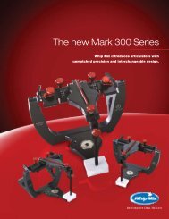
WHIP MIX <strong>4000</strong> SERIES ARTICULATORSModel 4640Model 46412
CONTENTSIntroduction .......................................................................................................................................... 4Operation Instructions for the Locking Mechanism............................................................................... 6Obtaining <strong>Face</strong>-<strong>Bow</strong> Registration.......................................................................................................... 7Direct Mounting the Maxillary Cast on the <strong>4000</strong> <strong>Series</strong> <strong>Articulator</strong> ...................................................... 9Mounting the Maxillary Cast using the Indirect Mounting Method ....................................................... 11Mounting the M<strong>and</strong>ibular Cast ............................................................................................................. 12Setting the Condylar Guidance of the Model 4640 <strong>and</strong> 4641 <strong>Articulator</strong>s ............................................. 13Setting the Condylar Inclination using a Protrusive Record .................................................................. 15Complete Denture Technigue ................................................................................................................ 16<strong>Whip</strong> <strong>Mix</strong> Recording System ................................................................................................................ 19Interchangeability with the <strong>4000</strong> <strong>Series</strong> <strong>Articulator</strong> ............................................................................... 20Reminders <strong>and</strong> Suggestions ................................................................................................................. 21Maintenance ......................................................................................................................................... 22<strong>Articulator</strong> Accessories ......................................................................................................................... 23<strong>Face</strong>-<strong>Bow</strong> Accessories .......................................................................................................................... 24<strong>4000</strong> <strong>Series</strong> <strong>Articulator</strong> Parts Lists <strong>and</strong> DiagramsModel 4640 <strong>Articulator</strong>......................................................................................................... 26Model 4640Q <strong>Articulator</strong> ...................................................................................................... 27Model 4641 <strong>Articulator</strong>......................................................................................................... 28<strong>Face</strong>-<strong>Bow</strong> Parts Lists <strong>and</strong> DiagramsModel 8645 <strong>Face</strong>-<strong>Bow</strong> (for Direct Mounting) ....................................................................... 29Model 9600 <strong>Face</strong>-<strong>Bow</strong> (for Direct Mounting) ....................................................................... 30Models 9175/9185/9195 <strong>Face</strong>-<strong>Bow</strong>s (for Indirect Mounting)............................................... 31Models 9275/9285/9295 <strong>Face</strong>-<strong>Bow</strong>s (for Indirect Mounting, Plastic Ear <strong>Bow</strong>) .................... 32Bibliography ......................................................................................................................................... 333
INTRODUCTIONThe WHIP MIX <strong>Series</strong> <strong>4000</strong> <strong>Articulator</strong> <strong>and</strong> “QUICKMOUNT” <strong>Face</strong>-<strong>Bow</strong> are designed to enable the user toquickly <strong>and</strong> easily mount casts of a patient’s jaws on a mechanical likeness that will reproduce their naturalrelationship <strong>and</strong> movements with an acceptable degree of accuracy. The simplicity <strong>and</strong> speed with whichthe necessary registrations are obtained <strong>and</strong> transferred to the WHIP MIX <strong>4000</strong> <strong>Series</strong> <strong>Articulator</strong> enable theoperator to accomplish corrective <strong>and</strong> restorative dentistry with much greater precision than has ever beforebeen possible.The WHIP MIX <strong>4000</strong> <strong>Series</strong> <strong>Articulator</strong> serves as an excellent auxiliary instrument for diagnostic <strong>and</strong>patient-education purposes. Being an “ARCON” type instrument, the WHIP MIX <strong>4000</strong> <strong>Series</strong> <strong>Articulator</strong> isideal for the study of occlusion <strong>and</strong> the movements of the temporom<strong>and</strong>ibular joint. With the condyle located onthe lower frame <strong>and</strong> the guidance on the upper frame (arcon design), WHIP MIX semi-adjustable articulatorshave become the preferred choice of many teaching institutions. Advancing to a fully adjustable articulatorbecomes a much easier process after having initial training on an arcon semi-adjustable articulator.As with all mechanical devices, the degree of perfection of the finishesd product depends to a greatextent on the operator’s comprehension of the results desired <strong>and</strong> on a complete underst<strong>and</strong>ing of thelimitations of the instrument being used. The instructions that follow in this manual make no attempt toteach concepts of occlusion <strong>and</strong> articulation. They simply outline a method to obtain a face-bow registration,itemize the other registrations needed, <strong>and</strong> detail their in setting the articulator.These instructions will deliver the minimum amount of guidance that is considered necessary <strong>and</strong> donot exhaust the capabilities of the articulator. Therefore, it is suggested that the operator refreshhis/her knowledge by reviewing one or more of the several excellent texts on subject of articulatorusage (see bibliography).The <strong>4000</strong> <strong>Series</strong> <strong>Articulator</strong> has the following features:• Ergonomic design.• Tracking Type of Condylar Guidance with Progressive Side Shift capability.• A permanent intercondylar width of 110 mm, which is the industry st<strong>and</strong>ard for Semi-Adjustable<strong>Articulator</strong>s with a fixed setting.• Fully open access from the lingual position for easy access during denture setup.• Easy to operate Locking Mechanism, which provides the following actions: In the locked positionit provides a quick way to return to centric position <strong>and</strong> locks the articulator for added stability. Inthe mid-range position the Locking Mechanism allows the condylar ball to move freely down thetrack of the condylar guides during excursive movements.4
• Capability of removing the upper member for greater access for cleaning <strong>and</strong> servicing thearticulator. To remove the upper member, simply push the spring-loaded release button locatedon the side of the condylar element <strong>and</strong> move the locking mechanism back to release thecondylar ball.• A Support Pin to support the upper frame of the articulator when open.• A built-in storage compartment for storing the Support Pin when not being used.• Ergonomically designed Condyle Locking Knobs for greater ease in locking the condyle inthe desired position.• Screw type mounting plates st<strong>and</strong>ard, but can be upgraded to include the <strong>QuickMount</strong>Magnet System.• Innovative “ACCUMOUNT” Mounting System of interchangeability. This will make it possible tointerchange mounted casts between any <strong>4000</strong> <strong>Series</strong> <strong>Articulator</strong> as found in the 2000 <strong>and</strong>3000 <strong>Series</strong> <strong>Articulator</strong>s.The main difference between the <strong>4000</strong> <strong>Series</strong> <strong>Articulator</strong> <strong>and</strong> traditional WHIP MIX <strong>Articulator</strong>s is theelimination of the crossbar between the uprights on the lower member. The Locking Mechanism isused as the primary source for securing the articulator in place.5
OPERATION INSTRUCTIONS FOR THE LOCKING MECHANISMa. When the tabs are in the “UP” position, the condyles are locked in centric. In this locked position, theoperator is assured that the articulator is locked in centric <strong>and</strong> ensures the stability of the articulator.b. Moving the tabs back one position places the Locking Mechanism in the mid-range position. In themid-range position the condyles can be moved down the tracking surface of the fossa element duringexcursive movements. The design of the Locking Mechanism prevents the user from accidentallyoverextending the lateral movements, which could destroy work in progress.The upper member of the articulator can be easily removed from the lower member if necessary forgreater access during cleaning <strong>and</strong> servicing of the articulator. To accomplish this, push the springloadedrelease button located on the outside of the fossa element while simultaneously rotating thelocking mechanism back. After unlocking one side, the upper member can be moved medially toseparate it from the lower frame.6
OBTAINING FACE-BOW REGISTRATIONFig. 1Items needed for a <strong>Face</strong>-<strong>Bow</strong> Registration:<strong>Face</strong>-bow including nasion relator <strong>and</strong>face-bow fork (bite fork)Elastomeric registration materialAdhesive for elastomericFig. 2Fig. 3I. Preparing <strong>Face</strong>-<strong>Bow</strong>Clean <strong>and</strong> properly disinfect the plastic earpieces before each use. If replacing them, makesure that the hole on the flat side of each isabove the side arm <strong>and</strong> the plastic is seateduntil it touches the shoulder of the earbow arm(Fig. 2). Note the ability of the nasion relatorassembly to move left <strong>and</strong> right along the crossbar <strong>and</strong> the face-bow caliper design allowingthe side arms to move equal distances duringthe opening <strong>and</strong> closing motions.Center the nasion relator assembly on the crossbar between the two centering indications.Loosen the #8604 thumb screws on the facebow<strong>and</strong> the #8643 thumb screws on thetransfer assembly.II. Preparing <strong>Face</strong>-<strong>Bow</strong> ForkElastomeric registration material may be usedas a bite registration medium for the bite fork.Make sure bite fork has been sterilized <strong>and</strong>apply sufficient registration material to the topsurface of the bite fork. Position the bite fork sothat the midline of the bite fork aligns with facialmidline <strong>and</strong> support the fork until the materialhas set (Fig. 3). The record should make ashallow registration of the maxillary cusp tips,<strong>and</strong> not perforate through the bite fork. Inspectregistration for tissue interferences <strong>and</strong> trimaway any that is found with a Bard-Parker Knife.III. Positioning <strong>Face</strong>-<strong>Bow</strong> onthe Patient <strong>and</strong> SecuringRegistrationBefore attempting to place the face-bow ontothe bite fork, it is suggested that the operatorrehearse the procedure with the patient. Cautionthe patient that the plastic ear pieces in theauditory canal will greatly amplify noises duringthe procedure. Support bite fork using cottonrolls placed underneath. A finger cot placed overeach ear piece will help facilitate properdisinfection of the face-bow.7
With the bite fork positioned in the patient’s mouth,start the toggle onto bite fork shaft while the patientholds the side arms close to the ears. Note: Makesure the horizontal cross bar is above the bitefork shaft (Fig. 4). Instruct the patient to place eachear piece into the external auditory meatus <strong>and</strong> holdin place with a firm forward pressure. Center the nosepiece on the patient’s nasion <strong>and</strong> exert firm pressureon the nose piece shaft while tightening the nasionthumbscrew. This action will help to firmly seat theear pieces into the external auditory meatus.Fig. 4With the patient continuing to hold onto the face-bow,position the toggle assembly on the bite fork shaft<strong>and</strong> slide until it is near, but not touching the lips <strong>and</strong>tighten the thumb screw. To prevent torquing of theface-bow <strong>and</strong> discomfort to the patient, support thefork <strong>and</strong> the horizontal bar with one h<strong>and</strong> whiletightening. Next tighten the thumb screw on thevertical bar while supporting the face-bow, againtaking care not to tilt the face-bow.Fig. 5Completed <strong>Face</strong>-<strong>Bow</strong> RegistrationIV. Removing <strong>Face</strong>-<strong>Bow</strong> from the PatientLoosen the nasion thumb screw <strong>and</strong> slide the nasion relator away from the patient’s nose. Loosen thethumb screws on the face-bow <strong>and</strong> have the patient pull the ear pieces out of their ears. The entire facebowassembly is removed by advising the patient to pull the ear pieces out of their ears while helping toremove the bite fork from the mouth.V. Obtaining Interocclusal RecordsNow is a convenient time to make the interocclusal records <strong>and</strong> set the condylar guidance of thearticulator. There are several materials available that may be used to make interocclusal records. Thematerial selected should complement the particular technique used. The following interocclusal recordsshould be utilized to relate the m<strong>and</strong>ibular cast to the maxillary mounting <strong>and</strong> to program the condylarguidance of the articulator:• Centric Relation <strong>and</strong>/or Maximum Intercuspation• Right Lateral• Left Lateral• Protrusive (optional)8
e used to support the bite fork during the mountingof the maxillary cast. The face-bow fork supportattaches to the lower frame in place of the lowermounting plate. The cross arms can be raised tocontact the under-surface of the face-bow fork toprevent flexing or movement of the fork (Fig. 9). Placemounting stone on the base of the cast <strong>and</strong> mountingplate. An inaccurate mounting will result if the bitefork flexes during mounting.Close the upper frame to contact the cross bar,Fig. 9bringing the mounting stone on the two surfacestogether. Do not use too thick of a mix of mountingstone or attempt to apply force when the stone has already begun to set. Keep the upper frame in thisclosed position until the mounting stone has set. If a device was used to secure the cast to the bite fork,carefully remove it <strong>and</strong> then remove the face-bow from the articulator. A second mix of mounting stonemay be used to fill in any voids left from the first mounting. Take care to avoid smearing excess mountingstone on the articulator parts.10
MOUNTING THE MAXILLARY CAST USINGTHE INDIRECT MOUNTING METHODI. Preparing the <strong>Face</strong>-<strong>Bow</strong> <strong>and</strong> <strong>Articulator</strong> for Mounting CastsObtain the face-bow registration in the usual manner.Remove the face-bow from the patient <strong>and</strong> unscrewthe locking screw on the cross bar holding thevertical rod. This releases the transfer assemblywhich holds the face-bow fork (Fig. 11). Attach the#8686 Support Bar to the top of the Vertical Rod <strong>and</strong>secure in place with the same locking screw (Fig. 12).With the #4611 Support Rod attached to the uppermember, rotate the upper frame of the articulatoruntil it is resting on the tabletop. This will make itFig. 10easier to install the transfer base assembly. TheIndirect Mounting <strong>Face</strong>-<strong>Bow</strong>#9176Q <strong>QuickMount</strong> Transfer Base Assembly is usedfor demonstration in this manual. If present, removethe mounting plate from the lower frame <strong>and</strong> install the #9176Q <strong>QuickMount</strong> Transfer Base Assembly.Fig. 11 Fig. 12II. Placing the <strong>Face</strong>-<strong>Bow</strong> Transfer Assembly on the <strong>Articulator</strong>Fig. 13Insert the vertical rod of the transfer assembly intothe transfer base assembly <strong>and</strong> lower it until thebottom of the vertical rod contacts the transfer base.Tighten the Clamp Screw so that the vertical rod fitssecurely in the transfer base (Fig. 13). Remove theincisal guide pin from the upper member. Place theupper frame of the articulator onto the lower frame sothe front of the upper frame now rests on the supportbar. Rotate the Locking Mechanism until the lever isin the “up” position. This locks the condyles againstthe posterior <strong>and</strong> superior walls of the fossa element.III. Mounting the Maxillary Cast(Refer to Direct Mounting the Maxillary Cast on the <strong>4000</strong> <strong>Series</strong> <strong>Articulator</strong> on page 9, part III.)11
MOUNTING THE MANDIBULAR CASTI. Preparing the <strong>Articulator</strong>The upper <strong>and</strong> lower frames are made parallel by aligning the top of the pin boss with the dark line, whichcompletely encircles the pin. The pin should then be adjusted 3–5 mm above the zero mark to compensatefor the thickness of the Centric Relation (CR) or Maximum Intercuspation (MI) registration used to mountthe lower cast. Make sure the Locking Mechanism tabs are in the “up” position. Set both progressive sideshift guides to the “0” position.Place the articulator upside down. This positions the mounted cast with its occlusal surfaces upward.Place an interocclusal CR or MI registration record on the maxillary cast, making sure the record iscompletely seated – no rocking should occur (Fig. 14). If you haven’t done so, cut retention grooves intothe base of the lower cast <strong>and</strong> properly wet it prior to mounting. Position the m<strong>and</strong>ibular cast on the CRor MI registration <strong>and</strong> check for stability.Fig. 14 Fig. 15For added stability, some clinicians use an alternate source to hold the upper <strong>and</strong> lower casts together.Hinge the lower frame into the open position <strong>and</strong> apply mounting stone to the base of the lower cast <strong>and</strong>the lower mounting plate. Hinge the lower frame closed until the incisal guide pin meets the incisal guideblock (Fig. 15). Make sure the condylar elements are seated flush against the posterior <strong>and</strong> superior wallsof the condylar guides. Carefully hold the articulator in this position until the mounting stone has set. Asecond mix of mounting stone may be used to fill in any voids left from the first mounting to produce apleasing aesthetic result.Finally, loosen the incisal guide pin screw <strong>and</strong> makesure the upper <strong>and</strong> lower casts contact. Retightenthe incisal guide pin screw <strong>and</strong> make sure the incisalguide pin is positioned in the center of the incisalguide block (Fig. 16).Fig. 1612
SETTING THE CONDYLAR GUIDANCE OFTHE MODEL 4640 AND 4641 ARTICULATORSAfter removing the CR or MI registration, release the centric lock by moving the tabs on the Multi-Functional Spring Mechanism to the mid-range position (Fig. 17). This allows the condyle mechanism tomove freely down the tracking surface of the fossa element. Loosen both condylar guides <strong>and</strong> set them tothe 0° setting indicated on the condylar inclination scale (Fig. 18). Firmly tighten the left condylar guidelocking knob <strong>and</strong> lightly secure the right condylar guide locking knob. Note: Set the progressive sideshift guides to their most open position (Fig. 19). Loosen the incisal guide pin screw <strong>and</strong> raise theincisal guide pin to prevent any interference. Retighten the incisal guide pin screw. Carefully seat the leftlateral excursion interocclusal record on the upper cast. It may be easier to perform this procedure withthe articulator inverted. While lightly holding the articulator together, make sure that the left condyle isseated “flush” against the rear wall. Gently seat the lower cast into the left lateral record <strong>and</strong> lightly holdthe articulator <strong>and</strong> casts in position. Note: The teeth of the cast should seat evenly into the leftlateral record. If the posterior teeth are raised out of the record the condylar inclination needs to bedecreased until the teeth are seated evenly in the record.Fig. 17 Fig. 18Fig. 19To set the inclination of the right condylar guide,carefully loosen the locking knob <strong>and</strong> rotate theguide until the teeth of the upper cast seat evenlyin the left lateral record. It is advisable whenmaking these adjustments that the contact shouldalso be judged by sight, rather than dependingsolely on the sense of touch. This helps ensure thatthe casts are not forced out of position. Tighten thecondylar guide locking knob to clamp the guide inposition. DO NOT USE EXCESSIVE PRESSUREwhen tightening the locking knob.13
Fig. 20To set the right progressive side shift, loosen the rightside shift holding screw <strong>and</strong> move the rightside shift guide until it touches the side of thecondyle element (Fig. 20). Retighten the right sideshift guide locking screw. Record the amount ofcondylar inclination <strong>and</strong> progressive side shift foundon the left side on a patient registration card. Afterthe right condylar guidance has been recorded,the condylar guidance should be neutralized aspreviously described. The left condylar guidance isadjusted using the right lateral excursion record<strong>and</strong> repeating steps listed above.14
SETTING THE CONDYLAR INCLINATIONUSING A PROTRUSIVE RECORDNeutralize the condylar inclination <strong>and</strong> progressive side shift settings. Place the protrusive record on themaxillary cast <strong>and</strong> gently seat the m<strong>and</strong>ibular cast into the protrusive record. It may easier to perform thisprocedure with the upper frame <strong>and</strong> its cast inverted. Both condylar elements will have moved away fromthe posterior surfaces of their respective condylar guides. Using sight <strong>and</strong> touch, rotate the left condylarguide until the teeth on the left side of the upper cast seat evenly into the protrusive record, then tightenthe condylar locking knob. Record the reading <strong>and</strong> repeat the procedure on the right side. Note: Thelateral records are used to determine the progressive side shift settings.I. Fabricating a Custom Incisal Guide TableTo prevent possible wearing away of the stone casts during manipulation of the articulator, or to make apermanent record of a specific case, the natural incisal guidance may be recorded. Fabrication of a customincisal guide is accomplished by adding a layer of self-curing resin to the Plastic Incisal Guide Block or theDovetail Incisal Guide Block. Raise the incisal guide pin 1–2 mm for fabricating the custom incisal guide.<strong>Mix</strong> enough acrylic to place approximately 1/4" on top of the incisal guide block.Carefully close the articulator in centric position <strong>and</strong> move the upper frame of the articulator back tosimulate a straight protrusive movement (end to end) (Fig. 21). From centric, move the upper member ofthe articulator to give a straight right lateral movement. Then, move the upper member of the articulator togive a straight left lateral movement. Move through all intermediate excursions between the lateral <strong>and</strong>protrusive positions (Fig. 22). Allow the acrylic to harden <strong>and</strong> trim off excess acrylic.Fig. 21 Fig. 22Fig. 23Custom Incisal Guide Table15
COMPLETE DENTURE TECHNIQUEI. Constructing Occlusion RimsContour the upper <strong>and</strong> lower occlusion rims, establish occlusal vertical dimension, apply the customarymarkings to the wax rims <strong>and</strong> establish a centric jaw relation record. Create wedge-shaped V indices in theocclusion rims.II. Preparing the <strong>Face</strong>-<strong>Bow</strong> ForkFig. 24Some clinicians prefer to utilize a pronged bite forksuch as the #8631 Offset Bite Fork (Fig. 24). Clean<strong>and</strong> properly disinfect the plastic ear pieces beforeeach use. Center the nasion relator assembly onthe cross bar. Loosen the #8604 thumb screws onthe face-bow <strong>and</strong> the #8643 thumb screws on thetransfer assembly.III. Preparing <strong>Face</strong>-<strong>Bow</strong>ArmamentariumFollow the procedures found on page 7.IV. Positioning the <strong>Face</strong>-<strong>Bow</strong>Make sure the midline of the palate <strong>and</strong> the stem of the bite fork is properly aligned. Position theface-bow onto the patient as described earlier on page 7. Once the face-bow record has been made,remove the wax rim <strong>and</strong> record base from the bite fork registration.V. Obtaining Interocclusal RecordsTo make jaw relation records, an elastomericregistration material or other appropriate recordmedium is placed onto the V indices of the wax rim(Fig. 25). The patient is guided into centric relation<strong>and</strong> is allowed to close until the wax rims come intocontact. The registration material is allowed to set<strong>and</strong> is then removed.VI. Preparing the <strong>Articulator</strong>for Mounting CastsFig. 25Many operators prefer to replace the plastic incisalblock with an adjustable metal table, such as the#2460 Adjustable Incisal Guide Table (Fig. 26). Remove the plastic incisal guide block from the articulator<strong>and</strong> install the adjustable incisal guide table. With the chiseled end pointed down, set the pin to the “0”mark, <strong>and</strong> adjust the position of the adjustable incisal guide table until the chiseled end of the incisalguide pin lies directly over the scribed line on the guide table (Fig. 27). Note: Guide pin must be setat “0” on the upper member.16
Fig. 26 Fig. 27VII. Mounting the Maxillary CastFollow the same procedures as described earlier, Direct Mounting the Maxillary Cast on the <strong>4000</strong> <strong>Series</strong><strong>Articulator</strong>, Mounting the Maxillary Cast using the Indirect Mounting Method.VIII. Mounting the M<strong>and</strong>ibular CastPlace the jaw relation record between the wax occlusion rims. Invert the articulator with casts attached <strong>and</strong>apply mounting stone. Additional jaw relation records can verify accuracy. Accurate fit of the verificationrecords into the V-shaped indices will denote a precise mounting.IX. Setting the Adjustable Incisal Guide TableAfter the anterior denture teeth are positioned, theadjustable guide table may be set.Fig. 28Release the locking mechanisms on the articulator.Loosen the #2472 Indicator Clamp Knob of theadjustable incisal guide table <strong>and</strong> bring the anteriorteeth into edge-to-edge contact. Adjust the inclinationof the guide table until it contacts the incisal pin thenretighten the thumb screw (Fig. 28). Move the teethin a left lateral relation <strong>and</strong> set the right wing of thetable. Repeat this same operation for the left wingin a right lateral position.X. Obtaining Protrusive RecordThe aesthetic try-in appointment affords the clinician the ability to verify tooth setup <strong>and</strong> obtain a wellindexedprotrusive record. The protrusive record should be created at an extended protrusive position toallow for bilateral condylar movement. Set condylar inclination on the articulator as described previously.17
XI. Fabricating a Remount IndexAfter denture processing, replace the mounting,cast, <strong>and</strong> denture onto the articulator. Attach the<strong>QuickMount</strong> Remount Jig on the lower frame(Fig. 29). Add sufficient stone to the remountjig to form an index of the cusp tips of thedenture teeth.Fig. 29XII. Remounting CastsAfter polishing, the maxillary denture can be mountedto the articulator for a clinical remount to evaluatethe denture occlusion. Using the remount index,mount the maxillary denture <strong>and</strong> remount cast tothe articulator (Fig. 30). Using new centric relationrecords, mount the m<strong>and</strong>ibular denture <strong>and</strong> remountcast. The denture occlusion may be evaluated <strong>and</strong>adjusted as needed.Fig. 3018
WHIP MIX RECORDING SYSTEMFor the clinician who desires a recording system, <strong>Whip</strong> <strong>Mix</strong> offers the #8450 QUICK SET RECORDER.The #8450 QUICK SET recording systems offers a time saving method for recording the protrusivecondylar path <strong>and</strong> measuring the amount of immediate side shift. The #8450 QUICK SET RECORDERprovides this information from an approximate hinge axis location.Listed below are other potential uses of the #8450 QUICK SET RECORDER. 11. Measurement of the timing or absence of a click during splint therapy.2. Comparison of click patterns in vertical opening <strong>and</strong> lateral <strong>and</strong> protrusive excursions.3. Setting an articulator for analysis or treatment.4. Comparison of eminence angles before side-to-side restorative dentistry.5. Estimates of eminence angles before surgical eminectomies.6. Measurement of condylar movement after TMJ surgery.Fig. 311 Bates, Robert E., Welsch, Boyd B., <strong>and</strong> Stewart, Carol M., “Temporo M<strong>and</strong>ibular Joint Disk Position as Determined by aSimple Recorder,” Journal of Prosthetic Dentistry, Vol. 56, No. 2, pp. 221-224, 1986.19
INTERCHANGEABILITY WITH THE<strong>4000</strong> SERIES ARTICULATORAll <strong>4000</strong> <strong>Series</strong> <strong>Articulator</strong>s feature the “ACCUMOUNT” Mounting System. The “ACCUMOUNT” Systemmakes it possible for the dental practitioner <strong>and</strong> the dental laboratory to interchange casts withoutexchanging articulators.During manufacture, each <strong>4000</strong> <strong>Series</strong> <strong>Articulator</strong> has a special table firmly <strong>and</strong> precisely attached to thelower frame using a special fixture <strong>and</strong> low-fusing alloy.The relationship between the upper <strong>and</strong> lower mounting plate is checked to verify precise alignment. Thisassures that casts can be interchanged between any <strong>4000</strong> <strong>Series</strong> <strong>Articulator</strong> without loss of accuracy.Features <strong>and</strong> Advantages1. When clinicians <strong>and</strong> dental students use a dental laboratory that has a <strong>Series</strong> <strong>4000</strong> <strong>Articulator</strong>,casts need no longer be mounted on an articulator when shipped to such laboratory.2. Clinicians can purchase fewer instruments while maintaining the same level of care fortheir patients.3. Instrument damage <strong>and</strong> lost parts caused by shipping the articulator to <strong>and</strong> from the dentallaboratory is eliminated.4. Precise alignment of the upper <strong>and</strong> lower frames is checked at the factory prior to shipping.20
REMINDERS AND SUGGESTIONS1. When securing interocclusal records to be used in mounting casts <strong>and</strong> setting the articulator,never allow the teeth to penetrate the recording material (impression compound, wax, gypsum,impression paste, etc.) too deeply. They should never contact the opposing teeth, the metalface-bow fork or any firm material that may be used as a carrying tray or h<strong>and</strong>le. Any recordshowing evidence of penetration should be discarded <strong>and</strong> remade.2. The more stable a recording material is, the more it will resist distortion during its later use.Any such material should be in a very soft state, however, during the initial recording procedure.3. The following technique may be used to secure interocclusal records of partiallyendentulous patients.If natural dentition opposes the edentulous space, the partial occlusion rim is built up to nearlytouch the opposing teeth. Zinc oxide <strong>and</strong> eugenol impression paste is then added to the surfaceof the occlusion rim of sufficient depth to register the tips of the opposing teeth when broughtinto the desired relationship.When the opposing spaces are both endentulous, one occlusion rim is built up in the customarymanner to near the occlusal plane, while the opposing rim is built to near this plane with smallcones of hard wax (or plastic) to indicate the registration in the impression paste.When absence of teeth makes it necessary to obtain interocclusal records on partial occlusionrims, these records must be made with the supporting soft tissue in as near a static conditionas is possible; some combination of these ideas can be planned to accomplish this withacceptable accuracy.4. With casts of unusually thin vertical dimensions, which would necessitate the use of a great bulkof mounting stone, it is suggested that the mounting plate be built up to near the correct thicknesswith a mix of mounting stone. This mix should be allowed to set for twenty minutes or longer beforethe actual mounting procedure is performed. This will minimize any effect of the gypsum settingexpansion on the mounting accuracy.5. It is suggested that a split cast mounting be made on the articulator before mounting the first case.This will be used for reference purposes should the articulator ever be dropped or mish<strong>and</strong>led.If the split cast mounting ever shows any discrepancy, return the articulator to the dealer forfactory recalibration at a nominal charge.21
MAINTENANCEThe <strong>Whip</strong> <strong>Mix</strong> Model 4640 <strong>Articulator</strong> is a sturdily constructed instrument that will provide manyyears of service with reasonable care. Both the upper <strong>and</strong> lower frames are made of cast aluminum.All aluminum parts are anodized to prevent corrosion or staining. Each condyle element consists of astainless steel shaft <strong>and</strong> durable plastic condyle ball. The condylar guide assemblies are made ofanodized aluminum.• Do not attempt to dislodge or remove the condyle ball from the condyle element shaft.• The sealing compound placed over the #8548 Set Screws should not be disturbed.• Do not attempt to remove the #2428 Screws holding each condyle release mechanism.• Avoid getting wax or stone in the screw holes which may damage threads.• Tighten screws snugly, but not too tightly. Overtightening the retaining screws can stripthe threads.• It is a good idea to use a carrying case when the articulator is transported. Dropping thearticulator may result in bent or broken parts which may affect the articulator’s ability toaccurately reproduce a patient’s m<strong>and</strong>ibular movements.• A thin film of lubricant (<strong>Whip</strong> <strong>Mix</strong> LUBRIPLATE) or silicone spray applied to the surface uponwhich the condylar elements move will provide a smooth action of these parts.• Failing to remove excess stone, or not keeping the articulator clean, may result in corrosionof the articulator surfaces.• Apply silicone spray to articulator frame to prevent plaster or stone from sticking to surfaces.• If you notice any bent parts on the articulator, have it serviced immediately to ensure itmaintains its interchangeability.22
ARTICULATOR ACCESSORIES#2460 Adjustable Incisal Guide #8533 Dovetail Incisal Block#8579Q <strong>QuickMount</strong> Remounting Jig #8575 Remounting Jig#8580B Plastic Mounting Plate #18156 Universal Tote Bag23
FACE-BOW ACCESSORIES#9186 <strong>Face</strong>-<strong>Bow</strong> Adaptors#8631 Offset <strong>Face</strong>-<strong>Bow</strong> Fork#8587 <strong>Face</strong>-<strong>Bow</strong> Fork Support#8585 <strong>Face</strong>-<strong>Bow</strong> Fork Support24
<strong>QuickMount</strong> Magnetic Transfer Base Assemblyfor Hanau 2 Pin <strong>Articulator</strong>s#9176A Transfer Base Assembly#9176Q <strong>QuickMount</strong> Magnetic TransferBase Assembly#8609 Bite Fork<strong>QuickMount</strong> <strong>Face</strong>-<strong>Bow</strong> Fork Support25
<strong>4000</strong> SERIES ARTICULATOR PARTS LISTS14151613181217111934352221108972425231202646321533322728293031MODEL 4640ARTICULATOR# PART# QTY. DESCRIPTION1 MA8543 2 FOOT BUMPER2 MA8527 1 INCISAL BLOCK SCREW3 MA4603 1 BOTTOM PLATE4 MA8526F 1 INCISAL BLOCK5 MA8344 1 MOUNTING TABLE (SHORT)6 MA2407 1 GUIDE PIN7 MA8509 2 PIN8 MA2444 1 BOSS9 MA8511 1 INCISAL PIN SCREW10 MA4601 1 TOP PLATE11 MA2410 1 BOSS12 MA2409 1 O-RING13 MA4611 1 TOP PLATE SUPPORT ROD14 MA4613 1 END BUMPER15 MA4605A 1 CONDYLAR GUIDE ASSEMBLY(RIGHT)16 MA2432 2 CLAMP KNOB17 MA2424 2 NYLON WASHER18 MA4606A 1 CONDYLAR GUIDE ASSEMBLY(LEFT)19 MA8519 2 FACE-BOW MOUNTING PIN20 MA2438 2 SET SCREW21 MA2408 2 CONDYLAR ELEMENT22 MA2422 2 HEX HEAD SCREW23 MA8810 2 PIN24 MA8545 2 #10 WASHER, STAINLESS STEEL25 MA8507 1 MOUNTING PLATE SCREW26 MA4602 1 UPRIGHT27 MA8345 1 MOUNTING PLATE SCREW28 MA8546 2 WASHER, BLACK FIBER, LARGE29 MA2042 2 ARTICULATOR FOOT30 MA8505 2 LEG31 MA8506 2 SCREW, SOCKET CAP32 MA8548 2 SCREW, SOCKET SET33 MA8508 2 MOUNTING PLATE KNOB34 MA8580 2 MOUNTING PLATE, METAL35 MA8580B 2 MOUNTING PLATE, PLASTIC26
14151613181217321119312221102320924865725126MODEL 4640QARTICULATOR432130 272829# PART# QTY. DESCRIPTION1 MA8543 2 FOOT BUMPER2 MA8527 1 INCISAL BLOCK SCREW3 MA4603 1 BOTTOM PLATE4 MA8526F 1 INCISAL BLOCK5 MA8344 1 MOUNTING TABLE (SHORT)6 MA2407 1 GUIDE PIN7 MA8509 2 PIN8 MA2444 1 BOSS9 MA8511 1 INCISAL PIN SCREW10 MA4601 1 TOP PLATE11 MA2410 1 BOSS12 MA2409 1 O-RING13 MA4611 1 TOP PLATE SUPPORT ROD14 MA4613 1 END BUMPER15 MA4605A 1 CONDYLAR GUIDE ASSEMBLY(RIGHT)16 MA2432 2 CLAMP KNOB17 MA2424 2 NYLON WASHER18 MA4606A 1 CONDYLAR GUIDE ASSEMBLY(LEFT)19 MA8519 2 FACE-BOW MOUNTING PIN20 MA2438 2 SET SCREW21 MA2408 2 CONDYLAR ELEMENT22 MA2422 2 HEX HEAD SCREW23 MA8810 2 PIN24 MA8724 1 13 mm HOLDER WITH NUT25 MA8726 2 MAGNET26 MA4602 1 UPRIGHT27 MA2042 2 ARTICULATOR FOOT28 MA8505 2 LEG29 MA8506 2 SCREW, SOCKET CAP30 MA8725 1 25 mm HOLDER WITH NUT31 MA8727 1 WRENCH32 MA8728 4 QUICKMOUNT PLATE WITH DISK27
1415 16131835121711193410897222324251212026652728MODEL 4641ARTICULATOR43213332293031# PART# QTY. DESCRIPTION1 MA8543 2 FOOT BUMPER2 MA8527 1 INCISAL BLOCK SCREW3 MA4603 1 BOTTOM PLATE4 MA8526F 1 INCISAL BLOCK5 MA8344 1 MOUNTING TABLE (SHORT)6 MA2407 1 GUIDE PIN7 MA8509 2 PIN8 MA2444 1 BOSS9 MA8511 1 INCISAL PIN SCREW10 MA4601 1 TOP PLATE11 MA2410 1 BOSS12 MA2409 1 O-RING13 MA4611 1 TOP PLATE SUPPORT ROD14 MA4613 1 END BUMPER15 MA4621A 1 CONDYLAR GUIDE ASSEMBLY(RIGHT)16 MA2432 2 CLAMP KNOB17 MA2424 2 NYLON WASHER18 MA4622A 1 CONDYLAR GUIDE ASSEMBLY(LEFT)19 MA8519 2 FACE-BOW MOUNTING PIN20 MA2438 2 SET SCREW21 MA2408 2 CONDYLAR ELEMENT22 MA2422 2 HEX HEAD SCREW23 MA8810 2 PIN24 MA8545 2 #10 WASHER, STAINLESS STEEL25 MA8507 1 MOUNTING PLATE SCREW26 MA4602 1 UPRIGHT27 MA8345 1 MOUNTING PLATE SCREW28 MA8546 2 WASHER, BLACK FIBER, LARGE29 MA2042 2 ARTICULATOR FOOT30 MA8505 2 LEG31 MA8506 2 SCREW, SOCKET CAP32 MA8548 2 SCREW, SOCKET SET33 MA8508 2 MOUNTING PLATE KNOB34 MA8580 2 MOUNTING PLATE, METAL35 MA8580B 2 MOUNTING PLATE, PLASTIC28
WHIP MIX FACE-BOW PARTS LISTSMODEL 8645FACE-BOWFOR DIRECT MOUNTING# PART# QTY. DESCRlPTlON1 MA8640 1 THUMB SCREW2 MA8643 1 THUMB SCREW3 MA2424 1 WASHER NYLON4 MA8617 1 SCREW5 MA8644 1 HORIZONTAL CLAMP ROD6 MA8608 1 SLIDE BAR ASSEMBLY7 MA8601 1 FACE-BOW (RIGHT)8 MA8603R 1 EAR PIECE (RIGHT)9 MA8603L 1 EAR PIECE (LEFT)10 MA8602 1 FACE-BOW (LEFT)11 MA8604 3 LOCKING SCREW12 MA8607 1 NOSE BLOCK13 MA8622 1 SCREW FOR UPRIGHT POST14 MA8606 1 NOSE PIECE SHAFT15 MA8605 1 UPRIGHT POST16 MA8609 1 BITE FORK17 MA8619 2 RETAINING RING18 MA8641 1 TOGGLE19 MA8616 1 LOCK WASHER20 MA8642 1 TOGGLENOT MA8549 PKG. OF 6 RUBBER-SHOWNBANDS29
MODEL 9600FACE-BOWFOR DIRECT MOUNTING# PART# QTY. DESCRlPTlON1 MA8640 1 THUMB SCREW2 MA8643 1 THUMB SCREW3 MA8617 1 SCREW4 MA2424 1 WASHER NYLON5 MA8644 1 HORIZONTAL CLAMP ROD6 MA8609 1 BITE FORK7 MA8608 1 SLIDE BAR ASSEMBLY8 MA9605 1 NUT9 MA9601-1 1 FACE-BOW (RIGHT)10 MA8603R 1 EAR PIECE (RIGHT)11 MA8603L 1 EAR PIECE (LEFT)12 MA9606A 3 SCREW13 MA9602-1 1 FACE-BOW (LEFT)14 MA8607 1 NOSE BLOCK15 MA8622 1 SCREW FOR UPRIGHT POST16 MA8606 1 NOSE PIECE SHAFT17 MA8619 2 RETAINING RING18 MA8605 1 UPRIGHT POST19 MA8641 1 TOGGLE20 MA8616 1 LOCK WASHER21 MA8642 1 TOGGLE22 MA8603A 1 EAR PIECE SOFT SETNOT MA8549 PKG. OF 6 RUBBER-SHOWNBANDS30
MODELS 9175/9185/9195FACE-BOWSFOR INDIRECT MOUNTINGWITH DB2000/2200/9000/9800ARTICULATORS# PART# QTY. DESCRlPTlON1 MA9180 1 SCREW, RD HEAD2 MA9183 1 CLAMP3 MA9182 1 FIXED CLAMP4 MA2424 1 WASHER NYLON5 MA9176 1 TRANSFER BASE6 MA8644 1 HORIZONTALCLAMP ROD7 MA8609 1 BITE FORK8 MA9177 1 VERTICAL ROD FOR#MA9175 FACE-BOWMA9187 1 VERTICAL ROD FOR#MA9185 FACE-BOWMA9196 1 VERTICAL ROD FOR#MA9195 FACE-BOW9 MA8686 1 SUPPORT BAR10 MA8679 1 CROSS BAR11 MA8601 1 FACE-BOW (RIGHT)12 MA8603R 1 EAR PIECE (RIGHT)13 MA8603L 1 EAR PIECE (LEFT)14 MA8604 4 LOCKING SCREW15 MA8602 1 FACE-BOW (LEFT)16 MA8622 1 SCREW FORUPRIGHT POST17 MA8607 1 NOSE BLOCK18 MA8606 1 NOSE PIECE SHAFT19 MA8605 1 UPRIGHT POST20 MA8619 3 RETAINING RING21 MA8641 1 TOGGLE CLAMP22 MA8616 1 LOCK WASHER23 MA8642 1 TOGGLE CLAMP24 MA8643 1 THUMB SCREW25 MA8640 1 THUMB SCREW26 MA9184 1 CLAMP SCREWNOT MA8549 PKG. OF 6 RUBBER-SHOWNBANDS31
MODELS 9275/9285/9295FACE-BOWSFOR INDIRECT MOUNTINGWITH 2240/2340/8340ARTICULATORS(PLASTIC EAR BOW)# PART# QTY. DESCRlPTlON1 MA9180 1 SCREW, RD HEAD2 MA9183 1 CLAMP3 MA9182 1 FIXED CLAMP4 MA9176 1 TRANSFER BASE5 MA2424 1 WASHER NYLON6 MA8644 1 HORIZONTALCLAMP ROD7 MA8609 1 BITE FORK8 MA9610 1 CROSS BAR ASSEMBLY9 MA8604 1 LOCKING SCREW10 MA8606 1 NOSE PIECE SHAFT11 MA8607 1 NOSE BLOCK12 MA9608 4 WASHER NYLON13 MA9607 2 SCREW BUTTON HEAD14 MA9601-1 1 FACE-BOW (RIGHT)15 MA8903R 1 EAR PIECE (RIGHT)16 MA8603L 1 EAR PIECE (LEFT)17 MA9602-1 1 FACE-BOW (LEFT)18 MA9606A 1 SCREW19 MA9605 1 NUT20 MA8622 1 SCREW FORUPRIGHT POST21 MA8619 3 RETAINING RING22 MA8686 1 SUPPORT BAR23 MA8641 1 TOGGLE24 MA8616 1 LOCK WASHER25 MA8642 1 TOGGLE26 MA8643 1 THUMB SCREW27 MA9177 1 VERTICAL ROD FOR#MA9275 FACE-BOWMA9187 1 VERTICAL ROD FOR#MA9285 FACE-BOWMA9196 1 VERTICAL ROD FOR#MA9295 FACE-BOW28 MA8640 1 THUMB SCREW29 MA9184 1 CLAMP SCREW30 MA8603A 1 EAR PIECE SOFT SETNOT MA8549 PKG. OF 6 RUBBER-SHOWNBANDS32
BIBLIOGRAPHYThe following bibliography gives more background on this instrument system.Bates, Robert E., Welsch, Boyd B., <strong>and</strong> Stewart, Carol M.:Temporo M<strong>and</strong>ibular Joint Disk Position as Determined by a Simple Recorder.J. Pros. Dent., Vol. 56 No. 2, 221-224, 1986.Cowan, Robert D., Sanchez, R.A., Chappell, R.P., Glaros, A.G., Hayden, W.J.:Verifying the Reliability of Interchanging Casts with Semi-Adjustable <strong>Articulator</strong>s.Inter. J. Pros. Dent., Vol. 4, No. 3, 260-264, 1989.Lee, Robert L.:Law Movements Engraved in Solid Plastic for <strong>Articulator</strong> Controls. Part 1,Recording Apparatus, J. Pros. Dent., 22:209, 1969.Lee, Robert L.:Jaw Movements Engraved in Solid Plastic for <strong>Articulator</strong> Controls. Part II,Transfer Apparatus, J. Pros. Dent., 22:513, 1969.Loos, Larry:Clinical Criteria Used to Select an <strong>Articulator</strong>, Compendium, Vol. XIV,No. 1, 80-82, 1993.Lundeen, Harry C., Wirth, Carl G.:Condylar Movement Patterns Engraved in Plastic Blocks. J. Pros. Dent.,30:866, 1973.Lundeen, H.C.:An Evaluation of M<strong>and</strong>ibular Border Movements: Their Character & Significance.J. Pros. Dent., 40:4424-452, 1978.Lupkiewicz, S.M., Ariet, M., Fujimoto, J., Gibbs, C.H., Lundeen, H.C., & Mahan, R.E.:Reproductibility of Border Movements, Part 1, 2 & 3. IADR Progr. & Abst. 57:No. 367 & 368, 1978.McCoy, R.B., Shyrock, E.F., & Lundeen, H.C.:A Method of Transferring M<strong>and</strong>ibular-Movement Data to Computer Storage.J. Pros. Dent., 36:510, 1976.Sokolow, Stanley M.:Interchangeable Quick-Mounted Study Models. J. Clinical Orthodontics,Vol. XX, No. 11:779-781, 1986.Welsch, Boyd B.:The Distribution of the Radius of the Curve Scribed During Protrusion.J. Pros. Dent., Vol. 51, No. 4:518, 1984.Special thanks to the Postdoctoral Prosthodontics Program at theUniversity of Texas Health Science Center at San Antonio.33
NOTES________________________________________________________________________________________________________________________________________________________________________________________________________________________________________________________________________________________________________________________________________________________________________________________________________________________________________________________________________________________________________________________________________________________________________________________________________________________________________________________________________________________________________________________________________________________________________________________________________________________________________________________________________________________________________________________________________________________________________________________________________________________________________________________________________________________________________________________________________________________________________________________________________________________________________________________________________________________________________________________________________________________________________________________________________________________________________________________________________________________________________________________________________________________________________________________________________________________________________________________________________________________________________________________________________________________________________________________________34
NOTES________________________________________________________________________________________________________________________________________________________________________________________________________________________________________________________________________________________________________________________________________________________________________________________________________________________________________________________________________________________________________________________________________________________________________________________________________________________________________________________________________________________________________________________________________________________________________________________________________________________________________________________________________________________________________________________________________________________________________________________________________________________________________________________________________________________________________________________________________________________________________________________________________________________________________________________________________________________________________________________________________________________________________________________________________________________________________________________________________________________________________________________________________________________________________________________________________________________________________________________________________________________________________________________________________________________________________________________________35
For additional information, contactour Technical Department at:<strong>Whip</strong> <strong>Mix</strong> Corporation361 Farmington Ave.P.O. Box 17183Louisville, KY USA 40217-0183502-637-1451800-626-5651Fax 502-634-4512www.whipmix.comMPL 30117 6/03