Pentamaran
Pentamaran
Pentamaran

Create successful ePaper yourself
Turn your PDF publications into a flip-book with our unique Google optimized e-Paper software.
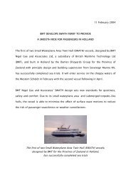
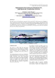
PATRICIA OLIVIA IIDEVELOPMENT OF THE FIRST 50+ KNOT FERRYIN NORTH AMERICAbyJohn Bonafoux, Technical Director, Nigel Gee and Associates LtdGavin Higgins, Shipyard Manager, Derecktor ShipyardsSUMMARYThe North American high speed ferry market has been slow to develop comparedwith other areas such as Australia, Europe and the Far East. However, recentdevelopments show that the US market is now gathering momentum, not only inrespect of the number of orders, but also with regard to the speed and sophisticationof the ferry designs. This trend was emphasised when, in September 1997, one ofthe world’s largest high speed ferry operators, Buquebus, placed a contract withDerecktor Shipyards in Mamaroneck, New York for a high specification, 300passenger ferry with a maximum speed of over 50 knots.This paper describes the design development, construction and sea trials of the Firstof Class of this new ferry design.INTRODUCTIONThe specification for the ferry required a maximum contract speed of over 50 knotsand a high level of seakeeping and passenger comfort. For design, DerecktorShipyards selected Naval Architects, Nigel Gee and Associates Ltd, with whom theyhad previously teamed for construction of the 38 metre high speed catamarans forNew York Fast Ferry, shown in Figure 1.The ferry was to be constructed for operation on a route between Fort Meyers,Florida and Key West or, alternatively, on a route across the river Platte betweenBuenos Aires, Argentina and Montevideo in Uruguay as shown in Figures 2 and 3.Passenger accommodation was provided for a total of 300 passengers, withapproximately 250 in a spacious main deck saloon, and 50 passengers in an upperdeck First Class lounge, as shown in Figure 4. The very high speed requirement ledto the selection of gas turbine engines using a Detroit Diesel TF80 propulsionsystem powering MJP waterjets.Construction of the vessel began in November 1997 with successful completion ofsea trials in October 1998, surpassing all contract requirements. The vessel is nowin operation between Buenos Aires and Montevideo.Principal particulars for the vessel are given in Figure 5.1
HULL DESIGN DEVELOPMENTOptimisation of hull form parameters for any vessel requires careful consideration ofmany influencing factors such as calm water performance, seakeeping, productioncosts and volume requirements for machinery etc. However, calm water resistanceis commonly the dominating factor, often at the expense of the vessel’s seakeeping,and the good design is the one which manages to balance these two importantcharacteristics.During the initial stage of the design, NGA completed a parametric study to establishthe preliminary dimensions for the catamaran hulls. As shown in Figure 6, hull formselection is highly dependent on the vessel’s Froude number. Due to the highFroude number for this design (Fn = 1.35), NGA’s early design work led to theselection of a “higher lift” warped chine hull design. This type of planing hull formwould normally be expected to be desirable at a Froude number in excess of 1.0.NGA’s analysis showed the total resistance of this hull form became morefavourable with increasing Froude number, compared to round bilge hull formscommonly used on 30-40 knot designs of the same length.Model tank testing was then conducted at the Marintek facility in Trondheim,Norway (see Figure 7). The tank testing programme included bare hull tests for trimoptimisation across a range of displacements and further testing with various sprayrail configurations. The addition of spray rails proved extremely beneficial with thefinal configuration reducing resistance by 5%.With a delivery period of only 14 months for design and construction of the vessel,NGA progressed the design of hull structure, machinery, systems and fitout inparallel with the hull design and tank testing. Detailed construction drawings werethen e-mailed to the shipyard, with construction proceeding alongside drawingapproval by ABS and USCG. Construction on this basis reduces the total designand build time, but increases the possibility of design changes during production.However, with careful design and liaison between all parties, this risk can bemanaged and changes during build were negligible.STYLINGToday, aesthetics play an ever increasing role in the vessel design of fast ferries. Tobring a fresh approach to the exterior of the vessel, leading Italian automotive andmarine stylists, Pininfarina, worked with NGA/Derecktor to develop styling whichwould give the vessel a stunning appearance, and would still allow ease ofconstruction in aluminium. The original Pininfarina rendering for the vessel is shownin Figure 8.Interior styling was completed by Julio Cesar Ortega Arquitecto, working closely withNicholson Interiors Ltd who supplied the lightweight honeycomb panels and surfacefinishes in kit-part form for assembly at the shipyard. The accommodation isarranged for 248 passengers on the main deck in a 3-4-4-3 configuration across the2
ship. The upper deck accommodation has capacity for a total of 56 passengers inClub Class seats with 4 of the passengers accommodated in a First Class privateroom. Both main deck and upper deck have bar areas for serving of drinks and lightsnacks.STRUCTURAL DESIGNThe hull and superstructure are of lightweight aluminium construction designed andbuilt to meet the requirements of the American Bureau of Shipping Regulations forthe Classification of High Speed Craft. The construction uses 5083-H321 plate,6061-T6 extrusions and extruded “T-Bar” planking for decks, superstructure,bulkheads and other flat areas of the structure. The typical structural style is shownin Figure 9. All plate was CNC cut to reduce production time. This included platefor transverse frames with folded flanges to reduce welding.Bottom structure in way of waterjets and machinery is an area that has suffered fromfailures on many other high speed ferries. To ensure reliability of not only thealuminium structure in this area but also the FRP waterjet intake ducts, a structuralanalysis using a finite element model (see Figure 10) of the engine room structurewas completed by CETEC Consultancy Ltd which included the skin, frames, girders,ducts and, where appropriate, machinery.The finite element model was also used to reduce the weight and cost of the powertransmission. The initial design incorporated a support bearing on the forward endof the waterjet shaft to prevent overloading of gearbox bearings. Using the model toconfirm the deflection envelope between the waterjet at transom and the gearboxoutput flange under any operating condition, allowed the forward shaft bearing andsupport structure to be deleted, with a valuable weight saving.MACHINERYGas turbine propulsion was preferred and the Detroit Diesel TF80 Marine Turbinewas selected as the most suitable power plant for the speed and payloadrequirement. The Detroit Diesel system uses a Cincinnati MA107 gearbox and twoAlliedSignal TF40 marine gas turbines, with a total power of 5.535 MW (7420 HP) ineach hull.Each pair of gas turbines are mounted directly onto the Cincinnati gearbox (seeFigure 11) which combines the power from each turbine and reduces the turbineinput speed of 15,400 rpm, into a single output shaft with a maximum shaft speed of765 rpm. Independent clutches on the turbine input shafts allow single turbineoperation for slower operating speeds. Power from the second turbine can bebrought on line almost immediately. The gearbox output shaft can also be clutchedto totally disengage power when alongside.3
For propulsion, Bird Johnson type MJP 950 DD waterjets were selected. Thiswaterjet design was a transitional model between the existing range and a newgeneration of high efficiency waterjets with improved cavitation performance. Toimprove waterjet performance the waterjet intake geometry was developed by MJPusing 3-D CFD analysis of the flow inside the intake and flow across the bottomsurface of the hull using incompressible, three dimensional flow calculation softwareas shown in Figure 12. NGA/Derecktor had previously used FRP waterjet intakes onthe NYFF ferries and to save weight and provide the highest quality surface on thewaterjet intake duct, this approach was also adopted on the Buquebus ferry (seeFigure 13).The machinery configuration and arrangement of the combustion air intake andexhaust is shown in Figure 14.To improve seakeeping, a Ride Control system from Maritime Dynamics Inc wasfitted. This system incorporates an active bow T-foil and stern trim tab on each hullto provide motion damping forces on each corner of the vessel. Photographs of theT-foil and trim tab assembly are shown in Figure 15.SAFETYThe vessel was designed and constructed as an “H-Boat” (ie to meet USCGrequirements under sub chapter H of the Code of Federal Regulations), over 100gross register tonnage and operating at a distance of up to 50 nautical milesoffshore. Under this category the major safety related build items were as follows.Liferafts:Marine Evacuation Slides:100% passenger capacity fitted to both sides ofthe vessel.One slide fitted at each liferaft embarkation station.Rescue Boat: USCG approved rescue boat andlaunching/recovery equipment .Fire Insulation-Engine Room:Fire Insulation-Accommodation:Area of safe refuge:A60 standard.E15 standard.140m 2 (minimum of 0.465m 2 per person)Weight is a critical factor on vessels of this type, and approval as an H-boat wasselected by Derecktors/NGA since it was thought that this would result in a vesselwith a high standard of safety without an excessive weight penalty. The vessel couldalso have been constructed under USCG as a “K-boat” (ie to meet USCGrequirements under sub chapter K of the Code of Federal Regulations) or,alternatively, as a high speed craft under the IMO HSC code. However, there is4
significant variation in these requirements which could result in ferries of the samespeed and passenger capacity, operating on the same route, yet fitted with verydifferent levels of safety equipment. It is felt that a more unified approach tocertification would be beneficial and would allow shipyards to construct vessels to amore consistent standard.CONSTRUCTIONR E Derecktor have been building vessels for over fifty years and built the firstaluminum yacht in North America. The basis of their success has been that in overfifty years of building boats, no vessel has ever suffered a major structural failure.Milestone boats, include Stars & Stripes, the last aluminum built 12 metre to win theAmerica's Cup; Encore, the 1996 Fastnet winner; and nine 270 feet Coast GuardCutters.Through the construction of the 45m ferry for Buquebus there were three majorpoints to be achieved:1. Achieve a very high speed requirement. This implies building within weightbudgets.2. Deliver on time.3. Deliver a high quality product.The weight of the vessel and fairness of the hull lines are critical to obtaining thespecified speed.For the weight, Derecktor monitored all components through the Engineering andPurchasing Departments, and investigated many different parts/materials to meetthe overall weight target.Reducing weight usually costs money but this can be cost effective if labour hoursare reduced. Fire insulation is a good example of this. The standard material usedin the United States is Rock Wool. To achieve an A60 rating with Rock Wool onaluminium requires 4" of material. Using a ceramic fibre insulation it is possible toreduce this to 2". Although the product is more expensive, there is a significantweight saving, and an added saving on installation time.Experience with yacht construction has enabled the production of a very fair hull.With great attention to accurate stiffener/plate fit up and careful weld schedule,plating distortion is minimised. This leads to a fair and geometrically accurate hull.Encouraged by the success of the composite water jet intakes on the two New YorkFast Ferries, Derecktor incorporated this construction method into the Buquebusvessel. The two New York Fast Ferries had run for a cumulative four years in NewYork harbour without any damage from floating debris or cavitation to the inside of5
the tunnels. Since each tunnel pumps approximately 175,000 gallons of water perminute through it, and would pump the Reflecting pool in Washington DC dry in 7minutes, extreme fairness is critical.On time delivery is very important to customers. To expedite production Derecktormade extensive use of the Internet to move the engineering files around the world.The exterior styling of the boat was from Italy, the engineering from England, thelofting and nest tapes from Seattle, the cutting in Florida and the construction in NewYork. The interior was designed in Uruguay and fabricated in Southampton,England.Each of these activities had to be approved by the Yard, and the Internet was theonly way to move the files around the world quickly and not hold up productionbecause of lack of information.In the future we will be able to reduce production time further by breaking the workdown into smaller packages and sub-contracting it to more vendors thus shorteningthe construction time.Derecktor have invested in techniques to minimise the stress build up in the platedue to welding. Examples of this are, firstly, to minimise the number of weldedseams/making a single pass butt weld, and secondly, to ensure continuity of thestiffeners and bracketing.SEA TRIALS AND PERFORMANCESea trials began in early October 1998 (see Figure 16). Unfortunately, there is stillno way of controlling the elements and, as is often the way, weather conditions werefar from ideal for speed trials on a vessel of this size with 15-18 knots of wind and a2-3ft sea throughout the trials period.The results of the full load speed trials are presented in Figure 17. Power wasconfirmed from calibrated torque measurements taken on the waterjet input shaft. Amaximum full load speed of 52 knots was achieved, although this was not at fullpower due to some early problems with the turbine fuel system. Another problemencountered during sea trials was recirculation of turbine exhaust gases into thecombustion air inlet, which can lead to a decrease in power and increasedmaintenance due to contamination of the turbine blades. This problem was quicklycured by adding deflector plates and side air inlets to locally increase air flow in wayof the combustion air inlets.Extrapolating to maximum power gave a fully loaded speed of 53 knots. Duringlighter weight trials with 12 tonnes of deadweight, the vessel achieved over 55 knots.Figure 17 also shows NGA’s performance prediction for the vessel and, as can beseen, the performance achieved during sea trials exceeded that calculated by NGA.It is thought that there were a number of factors contributing to this difference.6
Firstly, drag was initially calculated using a hull skin roughness allowance of 75microns. Later, it was decided to use “Intersleek” (a low friction paint systemmanufactured by International Paints Ltd) because of the significant reduction infrictional resistance that this would offer on a vessel of this speed. This siliconeelastomer based coating reduces surface roughness for a typical application to 44microns, thereby reducing the frictional component by approximately 7%. As can beseen from Figure 18, frictional resistance represents nearly one third of the total dragat speeds above 50 knots, and it is estimated that the reduction in surfaceroughness gives an increase in speed of approximately 0.75 knots. An addedbenefit of Intersleek is that it does not contain harmful biocides, resulting in a“greener” ferry. Weight control throughout the design and construction of the vesselwas another important factor with the final vessel weight being 1% lower thancalculated. In addition to these factors, the development work on the waterjet intakeand the high quality of the FRP intake ducts have resulted in higher efficiency, whichwas not included in the performance prediction.Speed trials on two-engine operation, ie one TF40 turbine on each side shut down,were also completed, with the vessel achieving a maximum speed of 40 knots.Sound measurement trials were completed with noise measurements taken by noiseconsultants, J & A Enterprises Inc, at various locations throughout the vessel withthe microphone held at approximately 1.5 metres above sole. At an early stage inthe design, NGA and Derecktor decided to pursue a philosophy of not fitting anysound insulation, other than the inherent sound deadening provided by fireinsulation, until noise measurements could be completed during trials. This simpleapproach allows for noise reduction to be applied exactly where it is required, with apotential saving in the weight of additional noise insulation which may not have beeneffective. Recorded noise levels taken during trials are given in Figure 19. Averagenoise levels within the lower and upper passenger saloons during initial trials were82 dB(A) and 76 dB(A) respectively. This trial also showed that noise generatedfrom the hull bottom with the vessel at high speed (115 dB(A) in forward voids) wascontributing significantly to the interior noise levels. Therefore, following this trial twoforms of noise reduction were installed. Firstly, polymer panels were applied toareas of the bottom structure to provide mass damping of these panels andsecondly, a layer of sandwich construction insulation with a high density middlelayer was applied across the underside of the deck in way of the passenger saloon.The combined effect of these treatments was to reduce the average noise level inthe lower deck passenger saloon to 75 dB(A) and to 72 dB(A) in the upper decksaloon.The performance data obtained from the sea trials has been corrected for theaddition of the bow T-foil drag and weight to confirm the final speed prediction withvarious engine options as shown in Figure 20.7
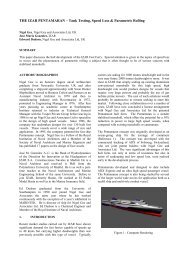
THE FUTUREThe Patricia Olivia II is the first ferry of its type to offer a fully loaded service speedin excess of 50 knots. However, there is an increasing requirement for even higherspeeds and to meet this need, NGA are currently working on a modified design ofthe NGA45m using 2 x Detroit Diesel TF100 Marine Turbine Systems to give fullyloaded speeds close to 60 knots.In addition to the current growth in larger high speed passenger/car ferries there is ahigh level of interest in 300 to 500 passenger ferries with very high operatingspeeds. Design and tank testing has already been completed by NGA for a 70 knot<strong>Pentamaran</strong> high speed passenger ferry as shown in Figure 21, and it is likely thatvessels with this order of speed will be in service in the year 2000.Looking further ahead, it is felt that the 100 knot ferry will be realized in the nextdecade and the challenge to industry will be to design and regulate these ultra fastvessels to ensure passenger safety.8
AUTHORS’ BIOGRAPHIESJOHN BONAFOUXSince graduating as a Naval Architect in 1983, John Bonafoux worked as aResearch Engineer for Vosper Hovermarine Ltd, before moving to WatercraftDefence and Commercial Division Ltd where he worked on the design of varioustypes of patrol craft. He then returned to work on the development of high speedferries at Vosper Hovermarine Ltd until 1986.He was a founding partner in Nigel Gee and Associates in 1986 and has sincebeen Technical Director of the company.GAVIN HIGGINSGraduated Southampton College in 1983 with a Degree in Naval Architecture.Worked for R E Derecktor in Rhode Island for two years on the 270ft USCGWMEC Cutters and 202ft Staten Island Ferries.Joined the Naval Architecture office of J W Gilbert & Associates of Boston,Massachusetts in 1985 and worked on a number of passenger ferries and fishingboat designs as well as various consultancy projects.Left Gilberts in 1988 to become the Chief Engineer of R E Derecktor inMamaroneck, New York where he has been responsible for the construction ofsail and motor yachts.In 1993 became a Chartered Engineer and in 1997 became the General Managerof R E Derecktor. Currently is a member of the Royal Institute of NavalArchitects and also, a member of the Society of Naval Architects and MarineEngineers.9
38m High Speed Catamaran FerryFor New York Fast FerriesDERECKTOR COMMERCIAL INC.Figure 1
NGA 45m High Speed CatamaranOperating Route - FloridaDERECKTOR COMMERCIAL INC.Figure 2
NGA 45m High Speed CatamaranOperating Route - Argentina / UruguayDERECKTOR COMMERCIAL INC.Figure 3
NGA 45m High Speed CatamaranGeneral ArrangementDERECKTOR COMMERCIAL INC.Figure 4
NGA 45m High Speed CatamaranPrincipal ParticularsDERECKTOR COMMERCIAL INC.LOALWLBeam MouldedDraughtSpeed (Full Load)45.60 m40.15 m11.80 m1.50 m52 knotsPassenger Capacity 300Figure 5
NGA 45m High Speed CatamaranHull Form OptimisationDERECKTOR COMMERCIAL INC.NYFF Fast Ferry Hull FormDesigned for 36 knots (Fn=1.0)Buquebus Fast Ferry Hull FormDesigned for 50 knots (Fn=1.3)Figure 6
NGA 45m High Speed CatamaranTank Testing At MarintekDERECKTOR COMMERCIAL INC.Figure 7
NGA 45m High Speed CatamaranExterior StylingDERECKTOR COMMERCIAL INC.Figure 8
NGA 45m High Speed CatamaranTransverse Structural ArrangementDERECKTOR COMMERCIAL INC.Figure 9
NGA 45m High Speed CatamaranFinite Element Model for Engine Room StructureDERECKTOR COMMERCIAL INC.Figure 10
NGA 45m High Speed CatamaranCincinnati MA107 GearboxDERECKTOR COMMERCIAL INC.Figure 11
NGA 45m High Speed Catamaran3-D CFD Model for Waterjet Inlet DesignDERECKTOR COMMERCIAL INC.MJP / MTDFigure 12
NGA 45m High Speed CatamaranFRP Waterjet Inlet DuctDERECKTOR COMMERCIAL INC.Figure 13
NGA 45m High Speed CatamaranMachinery ArrangementDERECKTOR COMMERCIAL INC.Figure 14
NGA 45m High Speed CatamaranRide Control System SurfacesDERECKTOR COMMERCIAL INC.Figure 15
NGA 45m High Speed CatamaranSea TrialsDERECKTOR COMMERCIAL INC.Figure 16
12000NGA 45m High Speed CatamaranTrials Results - Full Load Displacement(No T-Foil)DERECKTOR COMMERCIAL INC.110001000011070 kW10511 kW9000Sea Trial ResultsTotal Power (kW)800070006000NGA Predictions52 knots53 knots500040003000200020 25 30 35 40 45 50 55Speed (knots)Figure 17
NGA 45m High Speed CatamaranCalm Water ResistanceDERECKTOR COMMERCIAL INC.Total ResistanceFrictional ResistanceDrag25 27.5 30 32.5 35 37.5 40 42.5 45 47.5 50 52.5 55Speed (knots)Figure 18
NGA 45m High Speed CatamaranNoise Level TrialsDERECKTOR COMMERCIAL INC.85 Initial Sea Trial82After Noise Reduction80Noise Level (decibels)757076757267666560Lower PaxSaloonUpper PaxSaloonWheel HouseFigure 19
16000NGA 45m High Speed CatamaranCalm Water Performance With VariousMachinery Options(Full Load Displacement With T-Foil)DERECKTOR COMMERCIAL INC.14000120002 x TF100 (2 x 6.918 MW)Shaft Power (kW)10000800060002 x TF80 (2 x 5.535 MW)2 x Solar Taurus (2 x 4.6 MW)40002 x TF40 (2 x 2.77 MW)40 knots48 knots52 knots58 knots200020 25 30 35 40 45 50 55 60Speed (knots)Figure 20
NGA 45m High Speed CatamaranThe Future….70 Knot <strong>Pentamaran</strong> Passenger FerryDERECKTOR COMMERCIAL INC.Figure 21