Magnetic Resonance Imaging (MRI) - Office of Construction and ...
Magnetic Resonance Imaging (MRI) - Office of Construction and ...
Magnetic Resonance Imaging (MRI) - Office of Construction and ...

Create successful ePaper yourself
Turn your PDF publications into a flip-book with our unique Google optimized e-Paper software.
Department Of Veterans Affairs VA Space Planning Criteria (Chapter 275)Washington, D.C. 20402 June 2006DRAFT for Interim Use(Official Concurrence Pending)CHAPTER 275: VETERANS HEALTH ADMINISTRATION - MAGNETIC RESONANCEIMAGING1 Purpose <strong>and</strong> Scope ................................................................................................... 275-22 Definitions .................................................................................................................. 275-23 Operating Rationale <strong>and</strong> Basis <strong>of</strong> Criteria .................................................................. 275-34 Program Data Required (Input Data Questions) ........................................................ 275-55 Space Criteria ............................................................................................................ 275-56 Planning <strong>and</strong> Design Considerations ....................................................................... 275-107 Functional Relationship Matrix ................................................................................. 275-128 Functional Diagram 1 ............................................................................................... 275-139 Functional Diagram 2 ............................................................................................... 275-14<strong>Magnetic</strong> <strong>Resonance</strong> <strong>Imaging</strong> (Chapter 275): Page 1 <strong>of</strong> 14
Department Of Veterans Affairs VA Space Planning Criteria (Chapter 275)Washington, D.C. 20402 June 20061. PURPOSE AND SCOPEA. This document outlines space planning criteria for VA H<strong>and</strong>book 7610 Chapter 275:<strong>Magnetic</strong> <strong>Resonance</strong> <strong>Imaging</strong>. It applies to all medical facilities at the Department <strong>of</strong>Veterans Affairs (VA).2. DEFINITIONSA. Concept <strong>of</strong> Operations: A user-developed guide to the functional operation <strong>of</strong> the VAhealthcare facility. It defines the function <strong>of</strong> the facility <strong>and</strong> the scope <strong>of</strong> medicalservices to be provided in the new or remodeled space.B.C.D.E.F.G.H.Diagnostic Room: Designated room containing diagnostic equipment performingpatient procedures such as <strong>MRI</strong>. It may also be referred to as Scanning Room,Procedure Room, or Gantry.Functional Area: The grouping <strong>of</strong> rooms <strong>and</strong> spaces based on their function within aclinical service. Typical Functional Areas are Reception Areas, Patient Areas, SupportAreas, Staff <strong>and</strong> Administrative Areas, <strong>and</strong> Residency Program.Input Data Statement(s) : A set <strong>of</strong> questions designed to elicit information about thehealthcare project in order to create a Program for Design (PFD) based on the criteriaparameters set forth in this document. Input Data Statements could be Missionrelated, based in the project’s Concept <strong>of</strong> Operations; <strong>and</strong> Workload or Staffingrelated, based on projections <strong>and</strong> data provided by the VHA or the VISN about theestimated model <strong>of</strong> operation. This information is processed through mathematical<strong>and</strong> logical operations in VA-SEPS.<strong>Magnetic</strong> <strong>Resonance</strong> <strong>Imaging</strong> (<strong>MRI</strong>): The technique utilizing magnetic <strong>and</strong> radi<strong>of</strong>requency fields to produce computer calculated images <strong>of</strong> human anatomy (bodytissue) <strong>and</strong> monitor body chemistry. While immersed in a magnetic field, the portion<strong>of</strong> the body to be scanned is exposed to energy in the radio frequency range. Whenthe radio frequency is stopped, the nuclei return to a normal state. The effects <strong>of</strong> thisexposure on atomic nuclei position are read by the computerized system <strong>and</strong>converted into images. <strong>MRI</strong> reflects tissue density <strong>and</strong> body chemistry.Net-to-department gross factor (NTDG): A factor that when multiplied by theprogrammed Net Square Foot (NSF) area, determines the Departmental GrossSquare Feet (DGSF). The NTDG factor adopted for <strong>MRI</strong> is 1.60.Picture Archiving <strong>and</strong> Communication System (PACS): The digital capture, transfer<strong>and</strong> storage <strong>of</strong> diagnostic images. A PACS system consists <strong>of</strong> workstations forinterpretation, image/data producing modalities, a web server for distribution, printersfor file records, image servers for information transfer <strong>and</strong> holding, <strong>and</strong> an archive <strong>of</strong><strong>of</strong>f-line information. A computer network is needed to support each <strong>of</strong> these devices.Procedure / Suite Stop: A procedure / suite stop is one encounter <strong>of</strong> a patient with ahealthcare provider. Per these criteria, the procedure / suite stop is the workload unit<strong>Magnetic</strong> <strong>Resonance</strong> <strong>Imaging</strong> (Chapter 275): Page 2 <strong>of</strong> 14
Department Of Veterans Affairs VA Space Planning Criteria (Chapter 275)Washington, D.C. 20402 June 2006<strong>of</strong> measure for space planning. One individual patient can have multiple procedure /suite stops in a single visit or in one day.I. Program for Design (PFD): A space program based on criteria set forth in thisdocument <strong>and</strong> specific information about Concept <strong>of</strong> Operations, Workloadprojections <strong>and</strong> Staffing levels authorized.J.K.L.Room Efficiency Factor: A factor that provides flexibility in the utilization <strong>of</strong> a room toaccount for patient delays, scheduling conflicts, <strong>and</strong> equipment maintenance.Common factors are in the 80 to 85% range. A room with 80% room efficiencyprovides a buffer to assume that this room would be available 20% <strong>of</strong> the timebeyond the planned operational practices <strong>of</strong> the room. This factor may be adjustedbased on the actual <strong>and</strong>/or anticipated operations <strong>and</strong> processes <strong>of</strong> the room /department.SEPS (VA-SEPS): Acronym for Space <strong>and</strong> Equipment Planning System, a digital tooldeveloped by the Department <strong>of</strong> Defense (DoD) <strong>and</strong> the Department <strong>of</strong> VeteransAffairs to generate a Program for Design (PFD) <strong>and</strong> an Equipment List for a VAhealthcare project based on specific information entered in response to Input DataStatements. VA-SEPS incorporates the propositions set forth in this chapter as wellas all chapters in VA’s H<strong>and</strong>book 7610. VA-SEPS has been designed to aidhealthcare planners in creating a space plan based on a st<strong>and</strong>ardized set <strong>of</strong> criteriaparameters.Workload: Workload is the anticipated number <strong>of</strong> procedures or suite stops that isprocessed through a department/service area. The total workload applied todepartmental operational assumptions will determine overall room requirements bymodality.3. OPERATING RATIONALE AND BASIS OF CRITERIAA. Workload projections or planned services / modalities for a specific VA medicalcenter, hospital or satellite outpatient clinic project are provided by the VA Central<strong>Office</strong> (VACO) / VISN CARES Capacity Projection Model. Workload projections aregenerated by methodology based upon the expected veteran population in therespective market / service area. Health care planners working on projects for VAmedical centers, hospitals or satellite outpatient clinics, shall utilize workload criteriaset forth herein to determine room requirements <strong>and</strong> generate a space program foreach project.B. Space planning criteria have been developed on the basis <strong>of</strong> an underst<strong>and</strong>ing <strong>of</strong> theactivities involved in the functional areas <strong>of</strong> the <strong>Magnetic</strong> <strong>Resonance</strong> <strong>Imaging</strong> <strong>and</strong>their relationship with other services <strong>of</strong> a medical facility. These criteria are based onestablished <strong>and</strong>/or anticipated best practice st<strong>and</strong>ards, as adapted to provideenvironments supporting the highest quality health care for Vaterans.C. These criteria are subject to modification relative to development in the equipment,medical practice, vendor requirements, <strong>and</strong> healthcare planning <strong>and</strong> designdevelopments. The final selection <strong>of</strong> medical equipment for <strong>Magnetic</strong> <strong>Resonance</strong><strong>Magnetic</strong> <strong>Resonance</strong> <strong>Imaging</strong> (Chapter 275): Page 3 <strong>of</strong> 14
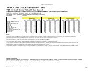
Department Of Veterans Affairs VA Space Planning Criteria (Chapter 275)Washington, D.C. 20402 June 2006<strong>Imaging</strong> is approved by VACO Radiology Service based upon Veterans HealthAdministration (VHA) anticipated medical needs.D. <strong>MRI</strong> Services, as used in these criteria, includes the diagnostic imaging modality <strong>of</strong><strong>Magnetic</strong> <strong>Resonance</strong> <strong>Imaging</strong> (<strong>MRI</strong>).E. Room capacity per year should be based on:Operating days per year x Hours <strong>of</strong> operation per day= Number <strong>of</strong>Minutes per procedure / 60 minutesannual procedures1. The general planning model for VA facilities assumes 250 Operating Days perYear <strong>and</strong> 8 Hours <strong>of</strong> Operation per Day. Room capacity will fluctuate as hours <strong>of</strong>operation are modified, i.e., additional capacity may be generated by extendingthe daily hours <strong>of</strong> operation within the same physical setting.2. Base Room Efficiency Factor is 80%.a. Modalities with routine, scheduled procedures <strong>and</strong> backup equipment (morethan one piece <strong>of</strong> the same type <strong>of</strong> equipment in the department) should planfor an efficiency factor <strong>of</strong> 85%.Example: Assume a modality room that averages 30 minute per procedure /suite stop:250 operating days per year x 8 hours <strong>of</strong> operation per day= 4,000 annual30 minutes per procedure / 60 minutes proceduresA maximum capacity <strong>of</strong> 4,000 procedures/suite stops per year, assuming100% utilization. However, 100% utilization is not realistic to achieve, thus, itis not an accurate design st<strong>and</strong>ard. Apply Room Efficiency Factor:4,000 x 80% = 3,200 annual procedures.TABLE 1: WORKLOAD PARAMETER CALCULATIONPROCEDUREAVERAGELENGTH OFPROCEDURE(minutes)ANNUALPROCEDURESPER ROOM(rounded)MINIMUMWORKLOAD TOGENERATE ONEROOM<strong>MRI</strong> Scanning Room 30 3,200 960The number <strong>of</strong> annual procedures per room will be used as a criteriaparameter to calculate the number <strong>of</strong> procedure rooms in the Space Criteriasection <strong>of</strong> this document. The minimum workload to generate one room is30% <strong>of</strong> the calculated annual procedures per room.<strong>Magnetic</strong> <strong>Resonance</strong> <strong>Imaging</strong> (Chapter 275): Page 4 <strong>of</strong> 14
Department Of Veterans Affairs VA Space Planning Criteria (Chapter 275)Washington, D.C. 20402 June 20064. PROGRAM DATA REQUIRED (INPUT DATA QUESTIONS)A. Mission Input Data Statements1. Is Teaching Viewing / Consultation authorized? (M)2. Is an <strong>MRI</strong> Residency Program authorized? (M)3. Is PACS authorized? (M)B.Workload Input Data Statements1. How many annual <strong>MRI</strong> procedures are projected? (W)C. Staffing Input Data Statements1. How many <strong>MRI</strong> FTE Data Processing employee positions are authorized? (S)2. How many <strong>MRI</strong> FTE Physicist positions are authorized? (S)3. How many <strong>MRI</strong> FTE Pr<strong>of</strong>essional Non Physician positions are authorized? (S)4. How many <strong>MRI</strong> FTE Quality Assurance specialist positions are authorized? (S)5. How many <strong>MRI</strong> FTE Staff Radiologist positions are authorized? (S)6. How many <strong>MRI</strong> FTE Scheduler positions are authorized? (S)7. How many <strong>MRI</strong> FTE Transcriptionist positions are authorized? (S)8. How many <strong>MRI</strong> Student positions are authorized? (S)9. How many Resident Intern positions are authorized? (S)D. Miscelaneous Input Data Statements1. How many FTEs for whom <strong>of</strong>fice space is not authorized? (MISC)2. How many FTEs for whom lockers are authorized? (MISC)3. How many male FTE positions are projected? (MISC)4. How many female FTE positions are projected? (MISC)5. SPACE CRITERIAA.Reception Areas1. Waiting (WRC01) .................................................................... 100 NSF (9.3 NSM)Minimum NSF. Provide an additional 45 NSF per each <strong>MRI</strong> Scanning Roomgreater than one.This area provides circulation <strong>and</strong> seating area for patients <strong>and</strong> visitors. TheWaiting Room should be connected to the patient entrance corridor <strong>and</strong> be undervisual control <strong>of</strong> the <strong>MRI</strong> receptionist.2. Reception (RECP1) .................................................................. 80 NSF (7.5 NSM)Minimum NSF. Provide an additional 10 NSF for each <strong>MRI</strong> Scanning Roomgreater than one.3. Patient Education Kiosk / Alcove (CLSC1) ............................ 30 NSF (2.8 NSM)Provide one per <strong>MRI</strong> Service.<strong>Magnetic</strong> <strong>Resonance</strong> <strong>Imaging</strong> (Chapter 275): Page 5 <strong>of</strong> 14
Department Of Veterans Affairs VA Space Planning Criteria (Chapter 275)Washington, D.C. 20402 June 20064. Public Toilet (TLTU1) .............................................................. 50 NSF (4.7 NSM)Provide one for male <strong>and</strong> one for female.B.Patient Areas1. Sub-Waiting (WROC1) ............................................................. 60 NSF (5.6 NSM)Minimum NSF. Add 15 NSF per each <strong>MRI</strong> Scanning Room greater than one.Locate near <strong>MRI</strong> Scanning Room.2. <strong>MRI</strong> Scanning Room (XMRS1) ........................................... 500 NSF (46.5 NSM)Divide the projected number <strong>of</strong> annual procedures by 3,200; provide one room foreach whole increment <strong>of</strong> 3,200 <strong>and</strong> remainder <strong>of</strong> 960 or greater. Minimum annualworkload to provide a room is 960 (see Table 1).Excludes control room. This room contains the high strength magnet, patienttable <strong>and</strong> related supporting hardware. The patient reclines on the table that fitsin the "bore" or the central, cylindrical part <strong>of</strong> the magnet. The <strong>MRI</strong> ScanningRoom requires radio frequency shielding to protect the scanning operation againstthe effects <strong>of</strong> common sources <strong>of</strong> radio frequency interference waves emanatingfrom external transmitters. <strong>Magnetic</strong> shielding may be required to control, shape<strong>and</strong>/or reduce the magnetic field <strong>of</strong> the scanner equipment. All equipment in thisarea should be made from non-magnetic material.3. Control Room (XMRC1) ...................................................... 120 NSF (11.2 NSM)Provide one per <strong>MRI</strong> Scanning Room.This room contains an operator console which consists <strong>of</strong> a computer terminal<strong>and</strong> image display monitors. The viewing window provides the operator with anunobstructed view <strong>of</strong> the patient within the scanner. The operator requires directaccess to both <strong>MRI</strong> Scanning Room <strong>and</strong> to the System Component Room fromthe control room. The operator controls the scanner operations <strong>and</strong> imagemanipulation such as acquisition, reconstruction, display <strong>of</strong> the images for variousstudies, <strong>and</strong> produces hard copy images through a multi-format camera. Provideaudio <strong>and</strong> closed circuit TV systems to communicate with the patient for closedtype<strong>MRI</strong> systems.4. System Component Room (XMRC2) ................................ 200 NSF (18.6 NSM)Provide one per <strong>MRI</strong> Scanning Room.This room contains the computer <strong>and</strong> most <strong>of</strong> the supporting electronic <strong>and</strong>electrical equipment. Typical hardware may include computer cabinets, powerdistribution unit, gradient cabinet, system control cabinet, radio frequency signalcabinet, shim <strong>and</strong> magnet power supply cabinets, radio frequency penetrationcabinets, power conditioner, <strong>and</strong> other system hardware. The room space allowsaccess for maintenance on two sides <strong>of</strong> the equipment <strong>and</strong> should be adjacent tothe control <strong>and</strong> <strong>MRI</strong> Scanning room.<strong>Magnetic</strong> <strong>Resonance</strong> <strong>Imaging</strong> (Chapter 275): Page 6 <strong>of</strong> 14
Department Of Veterans Affairs VA Space Planning Criteria (Chapter 275)Washington, D.C. 20402 June 20065. Viewing Room (XMRV1) ...................................................... 120 NSF (11.2 NSM)Provide one per <strong>MRI</strong> Scanning Room.A remote physician console provides the physician with the capability <strong>of</strong>independently viewing <strong>and</strong> manipulating images separate from the operatorconsole. It may also contain st<strong>and</strong>ard X-Ray illuminators. Requires authorizationby VACO Radiology Service.6. Dressing Room / Cubicle (DR001) ....................................... 35 NSF (3.3 NSM)Provide two per <strong>MRI</strong> Scanning Room.Room is to have convenient access to Patient Toilet, Waiting <strong>and</strong> <strong>MRI</strong> ScanningRoom. Personal property lockers provided in this space.7. Patient Stretcher Holding Bay (WRL01) ............................... 80 NSF (7.5 NSM)Provide one per <strong>MRI</strong> Scanning Room.Provides space for staging/observation <strong>of</strong> patient pre/post procedure.Patient scheduling should be managed so that not more than two stretcherpatients are present in the <strong>MRI</strong> suite at a given time. Also, this area is used forstorage <strong>of</strong> non-ferrous transport devices for transferring patients into the <strong>MRI</strong>Scanning room. This area should be adjacent to reception area where technicianscan see the patients because patients transported by mobile conveyances mayrequire closer supervision.8. Patient Toilet (TLTU1) ........................................................... 50 NSF (4.7 NSM)One minimum. Provide one per two <strong>MRI</strong> Scanning Rooms.This must be accessible from the Dressing Room / Cubicle <strong>and</strong> Waiting.9. Crash Cart Alcove (RCA01) ..................................................... 20 NSF (1.9 NSM)Provide one per <strong>MRI</strong> Service.C.Support Areas1. Gas / Cryogen Storage Room (SRGC2) ................................ 60 NSF (5.6 NSM)Provide one per <strong>MRI</strong> Service.This room contains the portable stainless steel dewars <strong>and</strong> cylinders containingliquid helium <strong>and</strong> liquid nitrogen. This refrigerant is used to produce lowtemperatures in cooling the magnet to approximately four degrees Kelvin. Thedewars h<strong>and</strong>ling equipment; siphons, cables, hoses <strong>and</strong> special connectors arealso stored in this room. Due to the weight <strong>and</strong> difficulty <strong>of</strong> moving the dewarsduring delivery <strong>and</strong> replenishment, access to the Gas / Cryogen Storage Roomshould be direct <strong>and</strong> without stairs. Empty dewars <strong>and</strong> cylinders are kept in thisroom until removed for refilling. This room needs a door opening that will allowpassage <strong>of</strong> dewars with diameter <strong>of</strong> up to 48" <strong>and</strong> a height <strong>of</strong> approximately 72".Venting to the outside is required for this room. The Gas / Cryogen StorageRoom should be located close to the <strong>MRI</strong> Scanning Room.<strong>Magnetic</strong> <strong>Resonance</strong> <strong>Imaging</strong> (Chapter 275): Page 7 <strong>of</strong> 14
Department Of Veterans Affairs VA Space Planning Criteria (Chapter 275)Washington, D.C. 20402 June 20062. PACS / Digital Quality Control Area (XVC01) ....................... 100 NSF (9.3 NSM)Provide one if in Concept <strong>of</strong> Operations.3. PACS / Digital Archival Storage Room (XFDS1) ................. 80 NSF (7.5 NSM)Provide one if in Concept <strong>of</strong> Operations.This room is utilized for the archiving <strong>of</strong> digital media. Shelving <strong>and</strong> a computerterminal without a printer may be located in this room.4. Film Processing Room (XFP01) .......................................... 80 NSF (7.5 NSM)Provide one if PACS will not be implemented.This space is for developing, film sorting, identification, tagging, film interpretation,<strong>and</strong> film image quality check. Room should be isolated from the main trafficcirculation pattern. Silver recovery tank <strong>and</strong> facilities for cleaning the processor<strong>and</strong> its rollers will be located in this area. Film processing capabilities may not berequired if adequate capacity is available for this function from another Service.5. Equipment Storage Room (XMRE1) ................................ 120 NSF (11.2 NSM)Provide one per <strong>MRI</strong> Service.This room is for the storage <strong>of</strong> specialized equipment required for imagingprocedures <strong>and</strong> should be located near the <strong>MRI</strong> Scanning Room. Items forstorage include: surface coils <strong>and</strong> coil holders, patient positioning accessories,<strong>and</strong> the calibration phantom kit.6. Stretcher / Wheelchair Storage (SRLW1) ............................... 40 NSF (3.8 NSM)Provide one per <strong>MRI</strong> Service.7. Linen Storage Alcove (LCCL1) ............................................... 20 NSF (1.9 NSM)Provide one per each <strong>MRI</strong> Scanning Room.8. Clean Supply Room (SRSE1) ............................................... 100 NSF (9.3 NSM)Provide one per <strong>MRI</strong> Service.9. Soiled Utility Room (USCL1) ................................................ 80 NSF (7.5 NSM)Provide one per <strong>MRI</strong> Service.The Soiled Utility Room provides an area for cleanup <strong>of</strong> equipment, utensils <strong>and</strong>for disposal <strong>of</strong> waste material.10. Housekeeping Aids Closet-HAC (JANC1) ........................... 40 NSF (3.8 NSM)Provide one per <strong>MRI</strong> Service.11. Viewing <strong>and</strong> Consultation Room /Non-teaching (XVC01) ......................................................... 120 NSF (11.2 NSM)Provide one per <strong>MRI</strong> Service.12. Viewing <strong>and</strong> Consultation Room /Teaching (XVC01) ................................................................ 240 NSF (22.3 NSM)Provide one if in Concept <strong>of</strong> Operations.<strong>Magnetic</strong> <strong>Resonance</strong> <strong>Imaging</strong> (Chapter 275): Page 8 <strong>of</strong> 14
Department Of Veterans Affairs VA Space Planning Criteria (Chapter 275)Washington, D.C. 20402 June 2006The Viewing <strong>and</strong> Consultation Room is the focal point <strong>of</strong> activity where staff <strong>and</strong>residents will review patient results. Activities also include training, film viewing,<strong>and</strong> reading.13. Staff Work Area (WRCH1) ........................................................ 80 NSF (7.5 NSM)Provide one per <strong>MRI</strong> Service.D.Staff <strong>and</strong> Administrative Areas1. <strong>Office</strong>, Chief Technician (OFA01) ..................................... 120 NSF (11.2 NSM)Provide one per <strong>MRI</strong> Service.2. <strong>Office</strong>, Staff Radiologist (OFDR1) ...................................... 120 NSF (11.2 NSM)Provide one per FTE position authorized.3. Cubicle, Administration (OFA01) ............................................ 80 NSF (7.5 NSM)Provide one per <strong>MRI</strong> Service.4. <strong>Office</strong>, Pr<strong>of</strong>essional Non Physician (OFA01) ..................... 120 NSF (11.2 NSM)Provide one per FTE position authorized.5. <strong>Office</strong>, PACS Administrator (OFA01) .................................. 120 NSF (11.2 NSM)Provide one if PACS is authorized.6. <strong>Office</strong>, Physicist (OFA01) .................................................. 120 NSF (11.2 NSM)Provide one per FTE position authorized.7. Cubicle, Data Processing Employee (OFA03) ........................ 80 NSF (7.5 NSM)Provide one per FTE position authorized.8. <strong>Office</strong>, Quality Assurance (OFDR1) .................................... 120 NSF (11.2 NSM)Provide one per FTE position authorized.9. Cubicle, Scheduler (OFA03) .................................................... 64 NSF (5.9 NSM)Provide one per FTE position authorized.10. Cubicle, Transcriptionist (OFA03).......................................... 80 NSF (7.5 NSM)Provide one per FTE position authorized.11. Copy Room (RPR01) .............................................................. 100 NSF (9.3 NSM)Provide one per <strong>MRI</strong> Service.The methodology below (12., 13., 14.) provides programming <strong>of</strong> Lounge, Lockers,Toilets at department/service/chapter level. Alternatively, sum alldepartments/services/chapters data for Lockers, Lounges <strong>and</strong> Toilets, <strong>and</strong> programspace in Chapter 410-EMS Lockers, Lounges, Toilets <strong>and</strong> Showers. Either/or – donot duplicate space in both this Chapter <strong>and</strong> Chapter 410.12. Staff Lounge (SL001) ........................................................... 160 NSF (14.9 NSM)Provide a minimum <strong>of</strong> 160 NSF; or 15 NSF for each FTE position authorized forwhom lockers are provided, whichever is greater.<strong>Magnetic</strong> <strong>Resonance</strong> <strong>Imaging</strong> (Chapter 275): Page 9 <strong>of</strong> 14
Department Of Veterans Affairs VA Space Planning Criteria (Chapter 275)Washington, D.C. 20402 June 200613. Staff Locker (LR001) ..................................................................... 6 NSF(.6 NSM)Per FTE position authorized for whom <strong>of</strong>fice space is not provided.14. Staff Toilet (TLTU1) .................................................................. 50 NSF (4.7 NSM)Divide the total male FTE positions authorized by 20. Provide one male toilet foreach whole increment. Minimum <strong>of</strong> 6 authorized male FTE positions to provide aseparate male toilet. Divide the total female FTE positions authorized by 15.Provide one female toilet for each whole increment. Minimum <strong>of</strong> 5 authorizedfemale FTE positions to provide a separate female toilet Minimum 1 combinedM/FM toilet.E. Residency ProgramThe methodology below provides programming <strong>of</strong> educational facilities atdepartment/service/chapter level. Alternatively, sum alldepartments/services/chapters data for educational facilities <strong>and</strong> program space inChapter 402- Educational Facilities. Either/or – do not duplicate space in both thisChapter <strong>and</strong> Chapter 402.Resident spaces should be grouped in one area close to the Viewing <strong>and</strong>Consultation Room.1. Cubicle, Resident Intern (OFA03) ........................................... 60 NSF (5.6 NSM)Provide one per resident position authorized <strong>and</strong> if in Concept <strong>of</strong> Operations.2. Cubicle, Student (OFA03) ........................................................ 30 NSF (2.8 NSM)Provide one per two student positions authorized <strong>and</strong> if in Concept <strong>of</strong> Operations.3. Conference / Classroom (CRR01) ....................................... 300 NSF (27.9 NSM)Provide one if in Concept <strong>of</strong> Operations.6. PLANNING AND DESIGN CONSIDERATIONSA. Net-to-department gross factor (NTDG) for Nuclear Medicine is 1.60. This number,when multiplied by the programmed net square foot (NSF) area, determines thedepartmental gross square feet (DGSF).B. Centralized staff administration <strong>and</strong> support should be considered to maximize staff<strong>and</strong> space efficiency.C. PACS reading stations maybe located centrally or remotely (in <strong>of</strong>fices); coordinationis required to avoid duplication <strong>of</strong> locations. It should be noted that for generalviewing by physicians outside <strong>of</strong> <strong>MRI</strong>, a typical flat screen monitor will suffice forreading <strong>of</strong> images. A high-end monitor system should be provided in areas wherephysician viewing / diagnosis occur within the Radiology Department or remotely.D. Provide separate outpatient intake <strong>and</strong> processing areas from inpatient circulation<strong>and</strong> holding areas when both patient types utilize the same department <strong>and</strong>/orprocedure rooms.<strong>Magnetic</strong> <strong>Resonance</strong> <strong>Imaging</strong> (Chapter 275): Page 10 <strong>of</strong> 14
Department Of Veterans Affairs VA Space Planning Criteria (Chapter 275)Washington, D.C. 20402 June 2006E. Verify room sizes <strong>and</strong> equipment layouts with imaging equipment vendors prior t<strong>of</strong>inalizing room layouts.F. The <strong>MRI</strong> suite should be functionally organized to separate staff <strong>and</strong> patientcirculation as much as possible. Diagnostic rooms, processing functions, staffworkstations, <strong>and</strong> staff support space should be organized contiguous to acentralized hub element for staff circulation. Patient waiting <strong>and</strong> public areas shouldbe organized in conjunction with a patient circulation element, which providesseparate access to diagnostic rooms <strong>and</strong> dressing rooms.G. Corridors should be designed to a minimum <strong>of</strong> 8 feet clear width, to accommodatepassage <strong>of</strong> equipment or beds <strong>and</strong> two stretchers <strong>and</strong>/or wheelchairs. In non-patientareas, corridors may be 6 feet in clear width.H. Locate all film file spaces to facilitate alternative use upon total implementation <strong>of</strong>PACS.I. <strong>MRI</strong> Scanning Room(s), Control Room(s) <strong>and</strong> System Component Room(s) shouldhave an emergency power supply to complete in-process procedures <strong>and</strong> permit safeegress <strong>of</strong> patients.J. Locate <strong>MRI</strong> units in an area with minimal potential electrical interference, even thoughmost <strong>MRI</strong> units today are self-shielded.K. A critical point in the quality <strong>of</strong> the images obtained from the <strong>MRI</strong> system is tomaintain a constant, homogeneous magnetic field in the center <strong>of</strong> the magnet. Thisrequirement for a homogeneous magnetic field could impose limitations on thelocation, construction <strong>and</strong> surroundings <strong>of</strong> the <strong>MRI</strong> suite. The homogeneity <strong>of</strong> themagnetic field can be distorted when large stationary ferromagnetic material (i.e.,steel frames, ferrous ductwork, etc.) are present in the vicinity <strong>of</strong> the <strong>MRI</strong> suite. Also,large moving ferrous masses <strong>of</strong> magnetic material like carts, elevators, stretchers,etc. can produce magnetic field fluctuations. The degree <strong>of</strong> distortion caused bythese ferromagnetic material depends on the magnetic field strength as well as on themass, orientation, permeability <strong>and</strong> saturation <strong>of</strong> the surrounding material.L. Refer to Department <strong>of</strong> Veterans Affairs (VA) <strong>Office</strong> <strong>of</strong> Facilities ManagementH<strong>and</strong>books, St<strong>and</strong>ards, St<strong>and</strong>ard Details, <strong>and</strong> Design Guides for technical criteria.<strong>Magnetic</strong> <strong>Resonance</strong> <strong>Imaging</strong> (Chapter 275): Page 11 <strong>of</strong> 14
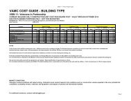
Department Of Veterans Affairs VA Space Planning Criteria (Chapter 275)Washington, D.C. 20402 June 20067. FUNCTIONAL RELATIONSHIPRelationship <strong>of</strong> <strong>Magnetic</strong> <strong>Resonance</strong> <strong>Imaging</strong> to Services Listed Below:TABLE 2: FUNCTIONAL RELATIONSHIP MATRIXRELATIONSHIP SERVICE REASONS2 Ambulatory Care (including ER) G,H2 Radiology Service G,H3 Cardiovascular Laboratories H3 Digestive Diseases Service H3 Intensive Care Nursing Units H3 Medical Research & Development A3 MS&N Nursing Units H3 Nuclear Medicine Service G,H3 Pulmonary Medicine H3 Radiation Therapy Service G,H3 Phys. Med <strong>and</strong> Rehabilitation Service H3 Spinal Cord Injury Center (SCI) H3 Surgical Service HRelationship:4 Audiology <strong>and</strong> Speech Pathology Service K4 Canteen Service / Dining Facilities D,E,K1. Adjacent2. Close / Same Floor3. Close / Different Floor Acceptable4. Limited Traffic5. Separation DesirableReasons:A. Common use <strong>of</strong> resourcesB. Accessibility <strong>of</strong> suppliesC. Urgency <strong>of</strong> contactD. Noise or vibrationE. Presence <strong>of</strong> odors or fumesF. Contamination hazardG. Sequence <strong>of</strong> workH. Patient convenienceI. Frequent contactJ. Need for securityK. Closeness inappropriate<strong>Magnetic</strong> <strong>Resonance</strong> <strong>Imaging</strong> (Chapter 275): Page 12 <strong>of</strong> 14
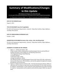
Department Of Veterans Affairs VA Space Planning Criteria (Chapter 275)Washington, D.C. 20402 June 20068. FUNCTIONAL DIAGRAM 1: <strong>MRI</strong> WITHIN RADIOLOGY SERVICE AREA RELATIOSHIP<strong>Magnetic</strong> <strong>Resonance</strong> <strong>Imaging</strong> (Chapter 275): Page 13 <strong>of</strong> 14
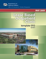
Department Of Veterans Affairs VA Space Planning Criteria (Chapter 275)Washington, D.C. 20402 June 20069. FUNCTIONAL DIAGRAM 2: <strong>MRI</strong> AREA RELATIONSHIP<strong>Magnetic</strong> <strong>Resonance</strong> <strong>Imaging</strong> (Chapter 275): Page 14 <strong>of</strong> 14