G78G/L LMS Instructions - AeroTech
G78G/L LMS Instructions - AeroTech
G78G/L LMS Instructions - AeroTech
- No tags were found...

Create successful ePaper yourself
Turn your PDF publications into a flip-book with our unique Google optimized e-Paper software.
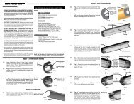
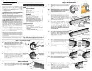
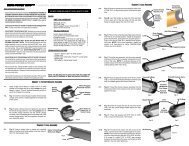
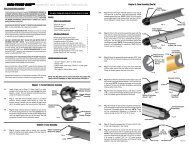
LOADABLE MOTOR SYSTEM Assembly and Operation <strong>Instructions</strong>READ THIS BEFORE YOU BEGIN:• Study the illustrations and sequence of assembly.THESEQUENCE OF ASSEMBLY IS EXTREMELY IMPORTANT.READ ALL INSTRUCTIONS BEFORE USE. USE MR-<strong>LMS</strong>MOTORS AND MOTOR KITS ONLY IN ACCORDANCE WITHALL INSTRUCTIONS. Review the parts list and become familiarwith all parts before assembly. IF ANY PARTS ARE MISSINGOR DAMAGED, CONTACT RCS AT 1-435-865-7100 OR EMAILat warranty@aerotech-rocketry.com.• DO NOT USE ANY PARTS OF THE MR-<strong>LMS</strong> SYSTEM THATARE DAMAGED IN ANY WAY. If in doubt, contact RCS at thenumber above for assistance.• DO NOT MODIFY THE MOTOR IN ANY WAY. Modification ofthe motor casing or the motor kit parts could result in motor failure,lead to the destruction of both your rocket and motor and maycause personal injury, death and/or property damage. Modificationof the motor casing or motor kit in any way will invalidate yourmotor warranty.• DO NOT RE-USE THE MR-<strong>LMS</strong> CASING AFTER FIRING.• USE ONLY AEROTECH/RCS MR-<strong>LMS</strong> MOTOR KITS ANDMOTOR PARTS TO LOAD AN MR-<strong>LMS</strong> MOTOR CASING.The <strong>AeroTech</strong>/RCS motor kits have been designed specificallyfor use in your particular <strong>AeroTech</strong>/RCS MR-<strong>LMS</strong> motor casing.Use of imitation components may destroy your motor, rocketand payload and will invalidate your motor warranty. Only use<strong>AeroTech</strong>/RCS MR-<strong>LMS</strong> motor kits intended for your specific<strong>AeroTech</strong>/RCS MR-<strong>LMS</strong> motor casing. DO NOT INTER-CHANGE PARTS! Do not use <strong>AeroTech</strong>/RCS MR-<strong>LMS</strong>motor kits or motor components for any other purpose than toload an <strong>AeroTech</strong>/RCS MR-<strong>LMS</strong> motor casing.• DO NOT ATTEMPT TO REUSE ANY OF THE PARTS OF THEMR-<strong>LMS</strong> MOTOR KIT. These components have been designedfor one use only and must be discarded after firing. Reusecan result in motor failure during subsequent operation and willinvalidate your motor warranty.• Read and follow the safety code of the National Association ofRocketry (NAR) and comply with all federal, state and local lawsin all activities involving model rockets.1-1. Apply a light coat of Synco Super Lube orother grease to the delay o-ring.DO NOT OPEN MOTOR KIT UNTIL READY TO USE.PARTS:MR-<strong>LMS</strong> MOTOR KITMR-<strong>LMS</strong> 29/120 casing 1Aft propellant grain (two green stripes,one magenta stripe) 1Forward propellant grain (two green stripes) 1Liner (3-1/2" long brown paper tube) 1MR-<strong>LMS</strong> 29mm forward closure 1Forward insulator (black fiber washer) 1Delay insulator (13/16" O.D. white paper tube) 1Delay o-ring (3/32" thick X 13/16" O.D.) 1RMS-Plus delay element (short solid part) 1Delay spacer (short colored paper ring) 1Ejection charge container (2-part red plastic cap) 1Ejection charge retainer cap (red rubber cap) 1FirstFire Jr. igniter 1Rubber band igniter holder 1Self-adhesive motor identification label 1ITEMS NEEDED FOR USE:Chapter 1. Forward Closure AssemblyDelayInsulator(Chamfered)• Super Lube or other grease• Hobby knife• 5-minute epoxy• Disposable rubber glovesDelayO-Ring2-1. Fig.-4: Install the propellant grains into the liner.NOTE: The use of disposable rubber gloves whenhandling Mojave Green propellant grains is stronglyrecommended.2-2. Fig.-5: Push the liner assembly into the motorcasing until it is seated against the nozzle end of thecase. NOTE: Place the liner assembly so that the aftpropellant grain (two green stripes, one magentastripe) faces the nozzle.2-3. Fig.-5: Install the forward insulator (black fiberwasher) into the motor casing until it is seatedagainst the liner assembly.2-4. Fig.-5: Mix about 5 grams of a good-quality 5-minute epoxy. Apply a liberal coat of epoxy to theinside surface of the casing in the threaded areaabove the liner assembly. CAUTION: Do not allowepoxy to contact the propellant grain surface.2-5. Fig.-6: Apply a liberal coat of epoxy to the threadedarea of the previously assembled forward closureassembly. CAUTION: Do not allow epoxy to contactthe delay grain surface. With the motor casing heldin a horizontal position, thread the forward closureassembly into the open end of the motor casing byhand until it is seated against the forward insulator.Apply additional epoxy to the joint between theforward closure and the case. Set the completedassembly aside to cure in a vertical position.3-1. Fig.-7: Carefully open the ejection chargecontainer (2-piece red plastic cap) and dispensethe ejection charge into the ejectioncharge well of the forward closure.Chapter 2. Case AssemblyPropellantGrainsAft GrainAt NozzleEndLinerAssemblyFig.-4Forward Closure Ass'yChapter 3. Ejection Charge InstallationEjectionChargeWellForwardInsulatorFig.-7Fig.-6CasingLinerApply Epoxy ToInner Surfaceand ThreadsCasingAssemblyFig.-5Apply Epoxy ToThreads andEnd JointEjection Charge1-2. Fig.-1: Chamfer both inner edges of the delayinsulator with your fingernail. Assemble theRMS-Plus delay element, delay insulator,delay spacer and delay o-ring as shown.1-3. Fig.-2: Apply a light film of grease to the innercircumference of the delay cavity (but not theforward end of the cavity).1-4. Fig.-3: Insert the delay charge assembly shownin Fig.-2 into the delay cavity, delay o-ring endfirst, until it is seated against the forward endof the MR-<strong>LMS</strong> forward closure.DelaySpacerApply Grease toThis SurfaceDelayChargeAssemblyDelay ChargeAssembly InsertedCompletely IntoMR-<strong>LMS</strong> ForwardClosureFig.-3Fig.-1Fig.-2RMS-PlusDelay ElementMR-<strong>LMS</strong>ForwardClosureDelayCavityDelayO-Ring3-2. Fig.-8: Press the ejection charge cap (redrubber cap) into the ejection charge well.3-3. Fig.-8: Release the air trapped under the capby puncturing the center of the cap using thesharp point of a hobby knife.3-4. Fig.-8: With the motor held in a NOZZLEDOWN position, gently shake the motor tosettle the ejection charge into the cavity abovethe delay element.3-5. Apply self-adhesive label to case to identifymotor type and delay. NOTE: The motor maybe fired as soon as the bulkhead epoxy hassolidified.EjectionChargeWellApply Labelto Center ofCaseFig.-8Ejection ChargeCap
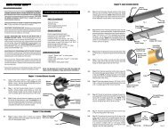
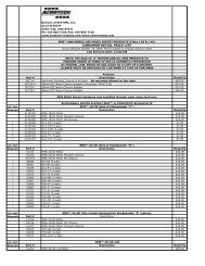
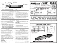
Nozzle ThroatInstall IgniterAgainst Delay ElementFig.-94-1. Fig.-9: Insert the coated end of the FirstFireJr. igniter through the nozzle throat until itstops against the delay element.4-2. Fig.-10: Bend the exposed end of the igniterinto an 'S' shape as shown. Place the rubberband over the nozzle extension to secure theigniter to the motor.4-3. Install the motor into the rocket's motor mounttube. Ensure that the motor is securely retainedin the rocket by using positive mechanicalmeans to prevent it from being ejected atthe time of ejection charge firing. NOTE: Whenusing MR-<strong>LMS</strong> motors to launch an Aero-Tech rocket kit, use the appropriate spacertubes and ensure that the motor clip snaps intoone of the slots in the nozzle end of the motorcasing and the motor clip firmly locks themotor into place.4-4. Prepare the rocket's recovery system andthen launch the rocket in accordance with theNational Association of Rocketry (NAR) SafetyCode and National Fire Protection Association(NFPA) Code 1122.Chapter 5. First AidDANGER: DO NOT INGEST PROPELLANT ORBREATHE EXHAUST FUMES! WASH HANDS AF-TER HANDLING MOJAVE GREEN PROPELLANTAND BEFORE EATING. For a minor burn, apply aburn ointment. For a severe burn, immerse the burnedarea in ice water at once and see a physician asquickly as possible. In the unlikely event of oralingestion of the propellant, induce vomiting and seea physician as quickly as possible. Mojave Greencomposite propellant consists primarily of AmmoniumPerchlorate, Barium Nitrate and a rubber-likeplastic elastomer.Chapter 4. Preparation For FlightFirstFire Jr. IgniterBent Into 'S' ShapeRubber BandIgniter HolderFig.-10Chapter 6. DisposalDamaged or defective MR-<strong>LMS</strong> motor kits shouldbe returned to RCS.Chapter 7. Fire SafetyTests show that the pyrotechnic components of MR-<strong>LMS</strong> motor kits will not explode in fires and normallywill not ignite unless subjected to direct flameand then will burn slowly. Use water to fight any firesin which <strong>AeroTech</strong>/RCS MR-<strong>LMS</strong> motor kit pyrotechniccomponents may become involved: Direct thewater at the <strong>AeroTech</strong>/RCS MR-<strong>LMS</strong> motor kit pyrotechniccomponents to keep them below their 550deg. F autoignition temperature. Foam and carbondioxide fire extinguishers will NOT extinguish burningpropellants of the type used in MR-<strong>LMS</strong> motorkit pyrotechnic components. Keep motor kit pyrotechniccomponents away from flames, sources of heatand flammable materials.Disclaimer and WarrantyNOTICE: As we cannot control the storage and use ofour products, once sold we cannot assume any responsibilityfor product storage, transportation or usage.RCS shall not be held responsible for any personalinjury or property damage resulting from thehandling, storage or use of our product. The buyerassumes all risks and liabilities therefrom and acceptsand uses <strong>AeroTech</strong>/RCS products on these conditions.No warranty either expressed or implied ismade regarding <strong>AeroTech</strong>/RCS products, except forreplacement or repair, at RCS's option, of thoseproducts which are proven to be defective in manufacturewithin one year from the date of originalpurchase. For repair or replacement under this warranty,please contact RCS. Proof of purchase will berequired. Note: Your state may provide additionalrights not covered by this warranty.Division of RCS Rocket Motor Components, Inc.WithRMS PLUSMODEL ROCKET <strong>LMS</strong> Loadable Motor System MR-<strong>LMS</strong> 29/120MOJAVE GREEN PROPELLANTTypical Time-Thrust Curve:DO NOT OPENMOTOR KITUNTIL READYTO USETHIS PACKAGE CONTAINS ONE MR-<strong>LMS</strong> MOTOR KIT:NOTE: To change delays, use <strong>AeroTech</strong> Reload Delay Kits (RDKs). For 4 second delay times, use RDK-38 Plus (.283" delay, .438" silver spacer). For 7 second delay times, use RDK-02 Plus (.375" delay, .344"red spacer). For 10 second delay times, use RDK-04 Plus (.469" delay, .250" orange spacer).Maximum recommended lift-off weights: G78-4G/L = 52 oz. (1474 grams), G78-7G/L = 32 oz. (907 grams), G78-10G/L = 20 oz (567 grams)NOTE: SALE TO PERSONS UNDER 18 YEARS OF AGE PROHIBITED BY FEDERAL LAW.DANGER-POISON: Contains Barium Nitrate. DO NOT INGEST PROPELLANT OR BREATHEEXHAUST FUMES. WARNING-FLAMMABLE: Read <strong>Instructions</strong> Before Use. KEEP OUTOF REACH OF CHILDREN. FOR USE ONLY BY INDIVIDUALS 18 YEARS OF AGE OR OLDER.DO NOT SMOKE when loading these motors or use in the vicinity of open flames.Thrust in PoundsTMAdvanced DelaySealing System2520151050G78-4G/LG78-7G/LCertified by the National Association of RocketryTime in SecondsG78-10G/L0.00 0.50 1.00 1.50MR-<strong>LMS</strong> 29/120 MOJAVE GREEN MOTOR KIT DATACasing Desig. Performance Desig. Total Impulse (Max.) Propellant Wt. Loaded Motor Wt.MR-<strong>LMS</strong> 29/120 <strong>G78G</strong>/L 112 N-sec 59.7 g (0.131 lb) 128 g (0.282 lb)<strong>AeroTech</strong> DivisionRCS Rocket Motor Components, Inc.Cedar City, UT 84720www.aerotech-rocketry.com20206 Rev. 11/11/08Made in U.S.A.©2008 RCS Rocket Motor Components, Inc., All rights reservedMR-<strong>LMS</strong> 29/120 CASING DATACasing Designation Motor Diameter Motor Length Casing Weight Motor Kit UsedMR-<strong>LMS</strong> 29/120 1.125" (29mm) 4.875" 49 g (0.108 lb) <strong>G78G</strong>/L