Capstone Design Document (pdf) - Capstone Experience
Capstone Design Document (pdf) - Capstone Experience
Capstone Design Document (pdf) - Capstone Experience

You also want an ePaper? Increase the reach of your titles
YUMPU automatically turns print PDFs into web optimized ePapers that Google loves.
<strong>Capstone</strong> <strong>Design</strong> <strong>Document</strong>Sponsor: Painless Performance ProductsFaculty Advisor: Professor George WrightDaniel Anderson-Project ManagerLarame Cummings-Systems EngineerRyan Moses-Hardware EngineerFebruary 1, 2007Prof George Wright: ________________________________Date: __________
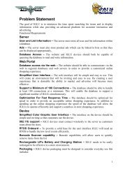
Conceptual Block DiagramThe conceptual block diagram for Striker Force presents all of the information needed foroperation. This is a general overview of Striker Force. The yellow boxes are devices or sensorsthat are outside of the module, while all of the blue boxes within the dotted box represent itemsfor the module. The conceptual block diagram for Striker Force is displayed in Figure 1.Performance RequirementsFigure 1 - Conceptual Block DiagramThe performance requirements take a further look into the functional requirements ofStriker Force. Each functional requirement has been expanded to show specific aspects of thatrequirement that need to be met.• Power from Engine Control Moduleo Voltage = 5Vo Amperage ≤ 1Ao Stop power usage when vehicle is turned off• Read MAP sensor outputso Acquire MAP sensor output voltageo Voltage ≤ 5Vo Output voltage used to manipulate boost pressure• Read Fuel Pressure sensor outputso Acquire Fuel Pressure sensor outputso Voltage ≤ 5Vo Output voltage used to manipulate fuel intakePage 2<strong>Capstone</strong> <strong>Design</strong> <strong>Document</strong> February 1, 2007
• Read temperature from pyrometero Acquire sensor output voltageo Used to ensure safe engine temperature• User interfaceo Output – Electronic display Voltage = 5V Amperage ≤ 50mA Pixels ≤ 128 X 64 Package size ≤ 2.75 X 1.25 X 0.5 (L X H X W) in inches Monochrome Graphical RS-232 communication Adjustable brightnesso Input – User controls Printed Circuit Board (PCB) Mountable Size ≤ .25 X .25 inches• Store initial settingso Storage ≤ 1Kb• Wiring harness connectiono MAP Sensor connectiono Fuel Pressure connectiono Pyrometer connectiono PCB connection• Self-contained and stand-alone unito Processor Power 16 or 32 bit processor Input/Output (I/O) lines > 10 lines Analog-to-Digital Converter (ADC) ≥ 1 ADC RS-232o Memory Flash ≥ 64Kb Random Access Memory (RAM) ≥ 5Kb• Handheld enclosure size and weighto Thickness ≤ 1.5 in.o Length and height ≤ 5 in.o Must be less than 2 lb.o Durability• Mountable – Striker Force moduleo On or around A pillar of vehicleo Good viewing angle – readable from mount• Wide temperature operationo Must be from at least -10°F to 135°FPage 3<strong>Capstone</strong> <strong>Design</strong> <strong>Document</strong> February 1, 2007
Striker Force will receive its power through the Engine Control Module, which will giveStriker Force 5 Volts. All information will have to be stored in memory for when the vehicle isswitched off. This is done to reduce power consumption and load on the battery of the vehicle.Striker Force will be a self-contained, stand alone unit that will be mounted in the cab of thevehicle. This unit will contain a processor, memory, and a user interface. The processor is thebrain of Striker Force and will control all the functions of the module. The processor will haveto be at least a 16 bit processor and have a minimum of 10 I/O lines. The processor will need tohave ADCs to facilitate communication with the various sensors. The final performancerequirement for the processor is RS-232. RS-232 is a standard that will allow for serialcommunications with the LCD.Technology Survey AssessmentNow that the functional requirements have been listed and the performance assessed, atechnology survey can be conducted to determine how each requirement will be met. Thissection addresses means of obtaining these functional requirements. Each requirement is listedand has three different technologies to meet those requirements. Along with each technology arepros and cons that help identify which technology is the best to meet the requirement. Thetechnology that best meets the requirement is then bolded.Power:• DC-DC Convertero Pros: Maintain 5V regulated signalo Cons: None• Voltage Regulatoro Pros: Maintain 3.3V regulated signalo Cons: Dropout Voltage• Batteryo Pros: Obtain 5V signalo Cons: Voltage spike, high amperageA DC-DC converter and voltage regulator were chosen to regulate power. The DC-DCconverter is used to regulate and maintain a 5V supply to the LCD. The voltage regulator waschosen to regulate and maintain a 3.3V supply to the microcontroller.Read MAP Sensor Outputs:• Input Captureo Pros: Up to 8 lineso Cons: None• Onboard ADCo Pros: High resolutiono Cons: NonePage 4<strong>Capstone</strong> <strong>Design</strong> <strong>Document</strong> February 1, 2007
• Analog I/O Porto Pros: ADCo Cons: NoneThe analog I/O port, onboard ADC, and input capture were chosen because of the signalscharacteristics and ease of use. Depending of the nature of the signal, one of the three will beused.Read Fuel Pressure Sensor Outputs:• Input Captureo Pros: Up to 8 lineso Cons: None• Onboard ADCo Pros: High resolutiono Cons: None• Analog I/O Porto Pros: Analog signalso Cons: 3.6V MaxThe analog I/O port and onboard ADC were chosen because of the signals characteristicsand ease of use. Depending on the nature of the signal, one of the three will be used.Read Temperature from Pyrometer• Input Captureo Pros: Up to 8 lineso Cons: None• Onboard ADCo Pros: High resolutiono Cons: None• Analog I/O Porto Pros: ADCo Cons: NoneThe analog I/O port and onboard ADC were chosen because of the signals characteristicsand ease of use. Depending on the nature of the signal, one of the three will be used.User Interface:Output:• Matrix Orbital GLK12232-25-WBo Pros: Readability, graphical, module sizeo Cons: Cost, Screen size• Matrix Orbital GLK12232-25o Pros: Graphicalo Cons: Cost, Screen sizePage 5<strong>Capstone</strong> <strong>Design</strong> <strong>Document</strong> February 1, 2007
• 3Mo Pros: Noneo Cons: NoneMolex connectors were chosen because it is already in use by Painless Performance.This will added continuity in products and ease in use.Self-contained and stand-alone unit:• Microchip 24H MCU Familyo Pros: 16 bit, 85 I/O lines, 2 ADCs, RS-232, I 2 C, Inexpensiveo Cons: Memory• Microchip dsPic33 DSC Familyo Pros: 16 bit, 85 I/O lines, 2 ADCs, RS-232, I 2 C, Inexpensiveo Cons: Memory• Freescale Coldfire 523X Familyo Pros: 32 bit, I/O lines, RS-232, I 2 C, Enhanced Time Processing Unit (eTPU),Memoryo Cons: No ADCs, ExpensiveThe Microchip Pic 24H MCU family was chosen because it meets all the functionalrequirements while being inexpensive. This family offers many modules that are needed fordevelopment of the Striker Force while not adding additional cost of a high performancemicrocontroller.Handheld Enclosure Size and Weight:• Plastico Pros: Inexpensive, Thickness, Lightweighto Cons: Durability• National Electrical Manufacturers Association (NEMA)o Pros: Durability, Lightweighto Cons: Expensive• Aluminumo Pros: Durability, Lightweighto Cons: ExpensiveThe plastic housing was chosen because of its physical characteristics as well as cost. Itis durable enough to withstand heavy usage as well as being lightweight and inexpensive.Mountable:• Suction Cup Mounto Pros: In use by Painless Performance, Universal, Inexpensiveo Cons: AestheticsPage 7<strong>Capstone</strong> <strong>Design</strong> <strong>Document</strong> February 1, 2007
• Velcroo Pros: Universal, Inexpensiveo Cons: Aesthetics• Bracketo Pros: Durabilityo Cons: ExpensiveThe suction cup mounting was chosen because it is already in use by PainlessPerformance and is a universal mount for all types of vehicles. This will simply suction to thewindshield of the vehicle and hold the module at a good viewing angle.Temperature:• Fan Cooledo Pros: Constant temperatureo Cons: Expensive, Power consumption• Heat Resistive Componentso Pros: Withstand temperature rangeo Cons: Added cost of components• Narrow the Temperature Range of User Operationo Pros: No added costo Cons: Will not work in all environmentsHeat resistive components were chosen because of cost and simplicity. With componentsthat can withstand high temperatures, no added circuitry will need to be added to reduce the heatof the module.Page 8<strong>Capstone</strong> <strong>Design</strong> <strong>Document</strong> February 1, 2007
Detailed Functional Block DiagramThe functional block diagram shows Striker Force in a more detailed view. This diagramshows part numbers for components along with voltages and the number of data lines. The lineswith a hash mark through them indicate more than one data line. The number following the hashmark shows how many data lines. The functional block diagram for the project Striker Force isshown by Figure 2.////Figure 2 - Functional Block DiagramPage 9<strong>Capstone</strong> <strong>Design</strong> <strong>Document</strong> February 1, 2007
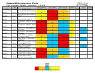
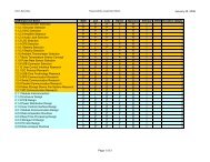
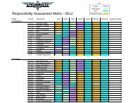
DeliverablesThe deliverables for the project bring value to the customer, showing the major steps takentowards completion. The deliverables have been grouped together by hardware, software, anddocumentation. The following diagrams, Table 1 and Figure 3, demonstrate who, what, andwhen all of the deliverables will be presented throughout the duration of the project. Alldeliverables listed are provided interim, unless noted otherwise.HardwareSoftware<strong>Document</strong>ationTable 1 - DeliverablesDeliverables Team Member DateSchematicLarameCummings2/6/07PCB <strong>Design</strong> Ryan Moses 2/8/07Bench Prototype Daniel Anderson 3/20/07In-Vehicle Ryan Moses 4/11/07Bench TestSignalGenerationProgramFlowchartCode ListingBench PrototypeTest PlanBench PrototypeTest ResultsIn-VehiclePrototype TestPlanIn-VehiclePrototype TestResultsSystem <strong>Design</strong><strong>Document</strong>ationTest ResultsLarameCummings2/19/07Daniel Anderson 1/30/07LarameCummings2/26/07Ryan Moses 3/20/07Daniel Anderson 3/27/07LarameCummings4/11/07Daniel Anderson 4/18/07Ryan Moses 5/1/07LarameCummings4/27/07InstallationGuideRyan Moses 4/26/07User Manual Daniel Anderson 4/20/07Page 10<strong>Capstone</strong> <strong>Design</strong> <strong>Document</strong> February 1, 2007
Figure 3 - Deliverable DatesHardware• Schematic (2/6/07) - Detailed visual representation of all the parts used to build StrikerForce and how each is integrated to the system. This schematic will be displayed in colorfor hard and soft copy created by using PSpice.• PCB <strong>Design</strong> (2/8/07) - The final arrangement of components on the printed circuit boardthat will allow for easy reproducibility.• Bench Prototype (3/30/07) - This prototype is a functional device that will be testedwithin the lab using a program that has calibrated signals representing simulated inputsignals.• In Vehicle Prototype (4/11/07) - The in vehicle prototype is the final module that willcontain the improvements from the dynamometer test. This module will be physicallyplaced on a diesel engine within a vehicle.Software• Bench Test Signal Generation (2/19/07) - This will be the code written to simulateengine signals for the in lab bench test.• Program Flowchart (1/30/07) - This is a visual display of the operations of the programwill take and how the information received by the engine.• Code Listing (2/26/07) – This is the copy of the code written that will be integrated onthe microcontroller for Striker Force.<strong>Document</strong>ation• Bench Prototype Test Plan (3/20/07) - The test plan will encapsulate all of the stepsneeded to verify that the Striker Force prototype works successfully within the lab underideal conditions.• Bench Prototype Test Results (3/20/07) - This document will contain all the results ofthe test plan for the bench top prototype.Page 11<strong>Capstone</strong> <strong>Design</strong> <strong>Document</strong> February 1, 2007
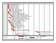
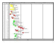
• In Vehicle Test Plan (4/11/07) - The in vehicle test plan will contain all of the changesthat are needed to ensure that the module works correctly on every diesel engine in anyvehicle.• In Vehicle Test Results (4/18/07) - This document will contain all of the results from thetest plan for the in vehicle prototype.• System <strong>Design</strong> <strong>Document</strong>ation (5/1/07) - This document is the reason why ADS ismaking this module. The system design contains the research obtained for the project,the test plan along with the results, and both the hardware and software principles desiredfor smooth transition of I/O. This document will be presented upon the completion of theproject.• Test Results (4/27/07) - The outcome of the tests performed on all of the differentcomponents used for Striker Force.• Installation Guide (4/26/07) -The installation guide will give the user information on thephysical installation of Striker Force. This document will be presented upon thecompletion of the project.• User Manual (4/20/07) - This will help and instruct the user on the operation of StrikerForce. This document will be presented upon the completion of the project.MilestonesMilestones are detailed events that describe and indicate that Striker Force is workingcorrectly with continuing progress. Each milestone fulfilled brings the project to its finalcompletion. The timeline for the milestones can be seen in Figure 4.Figure 4 - Milestones• Demonstration of Research (1/25/07) - The research will contain all of the necessaryinformation needed to understand all aspects of the project.• Demonstration of Module Components (2/2/07) - The final selection and use of thephysical parts needed to interface between the engine and the program.• Demonstration of Electronic Display (2/2/07) - This will be the user interface that willbe programmed to work with Striker Force.• Completion/Acceptance of Program (2/26/07) - The program design is needed to definethe scope for Striker Force. This will be previously debugged and tested to ensure properfunctionality. Demonstrated over <strong>Capstone</strong> Live Streaming Video.Page 12<strong>Capstone</strong> <strong>Design</strong> <strong>Document</strong> February 1, 2007
• Demonstration of Populated PCB (3/6/07) - This is where the components, which werepreviously researched and purchased within the module components milestone, aresoldered to the printed circuit board.• Demonstration of Tested and Completed PCB (3/14/07) - Testing and completing theprinted circuit board includes the testing of each individual component ensuring theircorrect functionality. The completion of this milestone will verify that the componentswere selected and are working correctly.• Completion/Acceptance of Bench Prototype (3/26/07) - The bench version of theprototype is tested by manually manipulating the inputs that the module receives andwhile able to monitor and change the output.• Completion/Acceptance of In Vehicle Prototype (4/17/07) - The in vehicle version ofthe prototype will be the final test for the module. The data input will be the truereadings obtained from a moving vehicle, thus allowing the module to work alone asdesired.• Demonstration of <strong>Document</strong>ation (5/1/07) - The documentation will include the usermanual, schematics, test plan and results. With these documents the user will knoweverything that is needed in order to work Striker Force.ConclusionDrivers will always find a need to have more performance from their vehicle. A solutionto this dilemma that is not only effective but inexpensive is Striker Force. ADS is committed toprovide this module, which improves horsepower, torque, and fuel efficiency for PainlessPerformance Products by the beginning of May 2007. With help and guidance from MikeAbbott and a grant from Painless Performance Products, ADS will provide a preproductionprototype with an individual cost no more than $200. ADS’s advisor, Professor George Wright,will help with technical problems and his experience in project management. All deliverableswill be presented to Painless Performance Products and Mr. Abbott, while all milestones will bepresented to Mr. Abbott and Professor Wright through weekly Technical Assessment Teammeetings.Page 13<strong>Capstone</strong> <strong>Design</strong> <strong>Document</strong> February 1, 2007