VENTURI AIR SPRAYERS 3-PT. HITCH MODELS - Gearmore, Inc.
VENTURI AIR SPRAYERS 3-PT. HITCH MODELS - Gearmore, Inc.
VENTURI AIR SPRAYERS 3-PT. HITCH MODELS - Gearmore, Inc.
- No tags were found...

You also want an ePaper? Increase the reach of your titles
YUMPU automatically turns print PDFs into web optimized ePapers that Google loves.
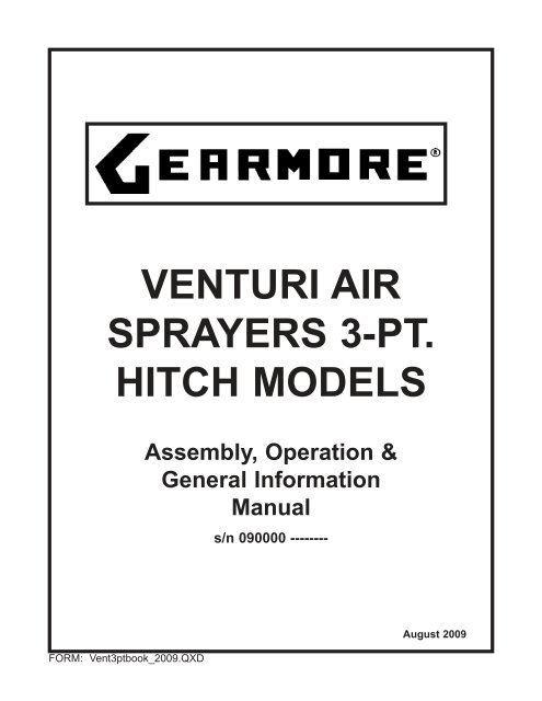
<strong>VENTURI</strong> <strong>AIR</strong><strong>SPRAYERS</strong> 3-<strong>PT</strong>.<strong>HITCH</strong> <strong>MODELS</strong>Assembly, Operation &General InformationManuals/n 090000 --------FORM: Vent3ptbook_2009.QXDAugust 2009
TABLE OF CONTENTSIntroduction . . . . . . . . . . . . . . . . . . . . . . . . . . . . . . . . . . . . . . . . . .1How To Operate The sprayer . . . . . . . . . . . . . . . . . . . . . . . . . . . .2Operation Of Ball Valve . . . . . . . . . . . . . . . . . . . . . . . . . . . . . . .3-4Important Information . . . . . . . . . . . . . . . . . . . . . . . . . . . . . . . . . .5Mounting To The 3-Point Hitch . . . . . . . . . . . . . . . . . . . . . . . . . . .6General Maintenance/Cleaning & Storage . . . . . . . . . . . . . . . . . .7Safety Decals . . . . . . . . . . . . . . . . . . . . . . . . . . . . . . . . . . . . . .8-10Important Notices . . . . . . . . . . . . . . . . . . . . . . . . . . . . . . . . . . . . .11General Safety Information . . . . . . . . . . . . . . . . . . . . . . . . . . . . .12Lubrication & Maintenance . . . . . . . . . . . . . . . . . . . . . . . . . . . . .13Fan Support Oil Level Check . . . . . . . . . . . . . . . . . . . . . . . . . . .14Main Strainer Maintenance . . . . . . . . . . . . . . . . . . . . . . . . . . . . .15Belt Tension . . . . . . . . . . . . . . . . . . . . . . . . . . . . . . . . . . . . . . . . .16Mounting Of Spray Heads . . . . . . . . . . . . . . . . . . . . . . . . . . . . . .17Modular System . . . . . . . . . . . . . . . . . . . . . . . . . . . . . . . . . . . . .18Limited Warranty: . . . . . . . . . . . . . . . . . . . . . . . . . . . . . . . . . . . .19Date of Purchase:__________________________Model Number:____________________________Serial Number:____________________________
INTRODUCTIONWe welcome you as an owner of the <strong>Gearmore</strong> Venturi Air Sprayer. This sprayer has the latest technicalfeatures and benefits that today’s market demands. Yet, the sprayer is quite simple to use and maintain.Before you read on to the operation and maintenance of the sprayer, please read the followinggeneral information.POWER SOURCE: The sprayer is designed to mount to any 540 RPM tractor with a 3-point hitch.PUMP: The pump on the sprayer is a low pressure centrifugal type. There is one very importantpoint to remember with centrifugal pumps; the pump uses the liquid to cool itself. Thus, if you runthe pump dry, it will be damaged quickly.TANK: The tank is thick walled polyethylene, which is corrosion resistant to most chemicals.BLOWER: Air is supplied by a centrifugal fan. The fan is made of steel and is precision balancedfor smooth operation. The fan housing is made of high strength polyethylene. A special overrunningclutch is mounted on the blower assembly to prevent damage.AGITATION: This sprayer features a unique dual agitation system, a liquid system that uses by-passliquid from the pump and an air system that uses air from the fan and introduces it to the bottom ofthe tank.ASSEMBLYThe sprayer comes almost completely assembled, so only a few steps are required:1. The air agitation control valve is shippedloose to prevent damage. Mount this valveand air hose assembly in the top of thetank by installing the lock nut on the insideof the tank. After installing the air valve,connect the air agitation hose that is insidethe tank to the nipple on the bottom of theair valve.2. Mount the distribution head onto the sprayerusing the clamps that are provided. Connectthe hoses and Dial-A-Rate metering system tothe distribution head distributors.3. Mount fan screen to housing.4. Install the rear bumper and adjust the height so that it does not obstruct the operation ofthe distribution head.Page 1
HOW TO OPERATE THE SPRAYER1. Connect the sprayer to the tractor 3-point hitch.2. Connect the <strong>PT</strong>O driveshaft after you have checked to make sure the driveshaft is not too long.Be sure to attach the <strong>PT</strong>O safety shield chains to the bottom crossbar on the sprayer and to thelower 3-point link arm on the tractor. After attaching, check the <strong>PT</strong>O shaft for correct length.There should be at least 1” - 2” clearance on the shaft when the sprayer is completely raised andlowered. Make sure there is less than a 15 o angle on <strong>PT</strong>O shaft (see page 6).3. Check the main filter strainer to make sure it is clean. Before cleaning the main filter, make surethe main ball valve (Ref. #1, page 3) is in the right position. When reassembling the filter strainer,make sure the large o-ring is seated properly.4. Refer to the calibration chart to set the correct rate for your application. Then set the “Dial-A-Rate” to correspond to the gallons per acre you require. On your <strong>Gearmore</strong> Venturi Air Sprayer,you will have a pressure control valve, which regulates the amount of pressure from 15 to 40 PSI.Remember when setting your pressure, the higher the pressure setting, the less liquid agitationyour tank will have. Also take into consideration that high pressure is not necessary when usingthe <strong>Gearmore</strong> Venturi Heads.5. Open the air agitation valve on the top of the tank to introduce air for added agitation.6. Engage tractor <strong>PT</strong>O at idle speed and run for a couple of minutes to make sure the chemicalsare mixed thoroughly. Engage transmission and bring engine speed up to <strong>PT</strong>O speed of at least540 RPM when spraying.7. Turn on the remote liquid control valve or electro-valve switches, depending on how yoursprayer is equipped. These valves can control right, left or both sides spraying, depending onwhat style of spray head you have mounted.Remember, it is always best to make a practice run with just water to be sure you havecorrect rates and coverage.Page 2
OPERATION OF BALL VALVESs/n 090000 ---------Page 3
IMPORTANT INFORMATIONMost Venturi heads have a liquid distributor on them (picture 1). All the tap assemblies (ref. B)have manual shut-offs. If these shut-offs are turned, it will cut off liquid flow to the hose comingoff that tap. Generally the factory leaves these taps all in the open position.In certain applications, such as with a T4+4 or T5+5 head (picture 2), you might not need all thenozzles putting out liquid. In this application what you should do is turn the shut-off to the horizontalposition to cut liquid off to the corresponding nozzles and then replace the Venturi nozzlewith a cap (part #02.127.000).Picture 1Venturi NozzleT4+4 T5+5Picture 2Page 5
MOUNTING TO THE 3-POINT <strong>HITCH</strong>It is absolutely essential that the connection be made so that when in use, the 2 power take-offpoints are running in line as close as possible (fig. 1). If not, the axes must be PARALLEL fromside to side (fig. 2) and the misalignment must be limited to prevent the universal joint workingat an angle of more than 15 o (fig. 3).Page 6
GENERAL MAINTENANCECarefully follow all instructions as stated in this operator’s manual, this includes lubrication, maintenanceand operation of the sprayer. The sprayer was designed and built for years of reliable service ifproperly cared for. However, this sprayer is a high RPM machine, thus attention is required.ƒ Check all bolts for tightnessƒ Check sprayer for leaksƒ Check main fan power beltƒ Check pump drive beltƒ Check to make sure no foreign objects are in or near the power systemCLEANING AND STORAGE1. Wash and flush out sprayer after completion of each phase of your spraying program.2. Flush out sprayer when changing chemicals if there is a possibility of incompatibility.3. Clean sprayer very thoroughly before storing at the end of the spraying season. If you are in acold climate, final rinse should be with a sufficiently concentrated anti-freeze to prevent freezeupin areas that were not thoroughly drained.4. Check sprayer over for needed repairs before time to spray again.5. Preparing the sprayer for use in the Spring means completion of all needed repairs, installationof all drain plugs and checking sprayer for leaks with a tank of water.SAFETY TIPSUUUUUUUUSprayer should be operated only by qualified persons.Always fill sprayer slowly to avoid spillage.When starting sprayer, maintain a safe distance from all moving parts.Never run <strong>PT</strong>O at speeds in excess of 540 RPM.Do not make adjustments when sprayer is running, unless specifically recommended.Never leave sprayer unattended while it is running.Keep hands, feet and clothing away from all moving parts.Handle chemicals carefully; follow the manufacturer’s directions for mixing and applyingchemicals.Page 7
SAFETY DECALSPage 8
SAFETY DECALSSAFETY DECALS1. 95001 - STOP THE ENGINE AND REMOVE THE KEY FROMTHE TRACTOR'S CONTROL PANEL BEFORE CARRYINGOUT ALL MAINTENANCE OR REP<strong>AIR</strong> OPERATIONS- Positioned on the left-hand side of the tank in the forward part ofthe machine.2. 95004 - DANGER OF CONTAMINATION BY CONTACT ORPOISONOUS PRODUCTS INHALATION- Positioned above the tank, in the forward part, next to the filler spout.3. 95005 - DANGER, PARTS IN MOTION. BEFORE REMOVINGPROTECTION GUARDS, STOP THE TRACTOR, REMOVETHE KEY FROM THE TRACTOR'S CONTROL PANEL ANDENSURE THAT ALL MOVING PARTS HAVE STOPPED- Positioned on the fan casing next to the outflow vent.5. 95010 - MAXIMUM OPERATING SPEED OF THE DRIVE OUTLET(<strong>PT</strong>O): 540 RPM- Positioned on the forward part of the machine, on the lower part of thetank and close to the drive outlet.6. 95007 - DANGER OF SPRAYS: KEEP AT A SAFE DISTANCE- Positioned on the upper part of the fan casing.7. 95006 - WARNING: CONSULT THE USER AND MAINTENANCEMANUAL BEFORE USING OR INTERVENING ON THEMACHINE- Positioned on the left-hand side of the tank, in the forward part ofthe machine.8. 95009 - DANGER: GLOVES MUST BE USED TO EM<strong>PT</strong>Y THE TANK- Positioned on frame behind drain ball valve.Page 9
SAFETY DECALSUSE & MAINTENANCE DECALS10. 95059 - HOOKING POINT FOR THE LIFTING OF THE MACHINE- Positioned on the frame, above the fan's casing.11. 95079 - CHECK THE OIL LEVEL EVERY 8 HOURS:FAN SHAFT BEARINGS (Not on P42N)- Positioned on the chassis, over the fan casing.12. 95054 - GREASE EVERY 200 HOURS: FAN TIGHTENERSUPPORT, FREEWHEEL AND WHEEL HUBS- Positioned on the chassis, in the low, rear side, on the left.- Positioned in the front section, on the tank, in a low positionnear the <strong>PT</strong>O.- Positioned on the wheel (accessory).13. 95060 - INDICATION OF THE WHEELS OPERATINGPRESSURE95056 - INDICATION OF THE WHEELS OPERATINGPRESSURE- Positioned on the wheel (accessory)14. 95057 - HAND WASHING TANK TAP- Positioned on the right hand side of the tank, next to the tap.15. 95065 - WARNING: NEVER OPERATE THE SPRAYER WITHOUTLIQUID IN THE TANK- Positioned on the forward part of the tank, above the gauge.16. 95076 - LUBRICATE EVERY 6 MONTHS: PUMP BEARINGS- Positioned on the unit's left side, on the chassis behind the pump.17. 95069 - INDICATIONS FOR THE USE AND MAINTENANCE OFTHE SOLENOID VALVES- Positioned on the tank, on the side of the electrical distributor.18. 95058 - INDICATION ON THE OPERATION OF THE 3-WAY TAP- Positioned on the left hand side of the tank, above the pump.Page 10
IMPORTANT NOTICETo obtain effective spray atomization and chemical agitation, you must operateyour tractor at recommended maximum engine RPM to obtain correct <strong>PT</strong>O speedof 540 RPM.DO NOT ALLOW POWDER CHEMICALS TOSTAY IN THE TANK WITHOUT AGITATIONPowder chemicals that do not dissolve will settle to the bottom of the tank whenthe agitation is stopped and may damage the pump when it is restarted.NEVER USE A STICKER PRODUCT WITH TEFLON,BOND OR TACTIC INGREDIENTSIf a sticker is needed, <strong>Gearmore</strong> recommends Latron B1956 or compatible products.AFTER EACH USEBEFORE STORING THE SPRAYER1. Be sure to drain and clean out the tank.2. Run clean water through the entire system.3. Remove the cap on the front of the pump.4. Remove and clean the main filter.Page 11
GENERAL SAFETY INFORMATIONDO NOT OPERATE PUMP WITHOUT LIQUID IN TANKWARNING:Do not pump flammable or explosive fluids such as gasoline, fuel oil, kerosene,etc. Do not use in explosive atmospheres. The pump should be used only withliquids compatible with the pump component materials. Failure to follow thiswarning may result in personal injury and/or property damage and will voidthe product warranty.+ Do not operate pump above recommended RPM.+ Operate pump between 45 o F and 145 o F liquid temperatures.+ Make certain that the power source conforms to the requirements of yourequipment.+ Provide adequate protection in guarding around the moving parts suchas the shaft and pulleys.+ Disconnect power before servicing.+ Release all pressure within the system before servicing any component.+ Drain all liquids from the system before servicing.+ Secure the discharge lines before starting the pump. An unsecureddischarge line may whip, causing personal injury and/or property damage.+ Check hoses for weak or worn conditions before each use. Make certainthat all connections are tight and secure.+ Periodically inspect the pump and the system components. Performroutine maintenance as required (see Maintenance section).+ Do not use these pumps for pumping water or other liquids for humanor animal consumption.Page 12
LUBRICATION & MAINTENANCE1. Located on the back side of the pump is an oil reservoir. Using an oil can, add approximately10 drops of SAE 15W40 engine oil every 6 months of use.2. The oil fill for the fan support bearings is located behind the fan housing and in front of themain frame by the fan housing. Check the oil every 8 hours of use. The oil needs to bechanged yearly. (Note: Models P45N1, P50N1, P50S1 and P55S1)3. The grease zerk for the fan bearing assembly is located on the left side of the fan housing.Grease this zerk every 20 hours of use. (Note: Model P42N1 only)4. The main drive belt idler assembly has sealed bearings, but the idler needs to be greased every200 hours to allow it to pivot freely. This grease zerk is located on the right main frame by thefan housing.5. The overrunning clutch is designed to allow the fan assembly to rotate freely when the tractor<strong>PT</strong>O is shut down. This grease zerk is located behind the <strong>PT</strong>O driveline and requires you toremove the <strong>PT</strong>O to lubricate. Grease this zerk every 200 hours of use.6. The <strong>PT</strong>O driveshaft u-joints should be greased every 8 hours and the shafts every 20 hours.The <strong>PT</strong>O safety shields have a plastic zerk for the shield bearings that should also be greasedevery 20 hours.#4#2#1#3#5Page 13
FAN SUPPORT OIL LEVEL CHECK1. Unscrew and remove the oil filling plug with dipstick.2. Clean the dipstick and reinsert in oil tube.3. Remove dipstick and check oil level. Oil should be between the min. and max. marking ondipstick. If oil is low add SAE 90 wt. oil.4. Reinstall dipstick and re-tighten.CHANGING FAN SUPPORT OIL1. Unscrew and remove the oil filling plug with dipstick.2. Remove the oil drain plug and drain oil completely.3. Replace oil drain plug.4. Through the filling pipe, pour SAE 90 wt. oil to proper level on dipstick.5. Reinstall dipstick and re-tighten.Page 14
MAIN STRAINER MAINTENANCEMAIN STRAINER:Clean strainer screen before each treatmentand when required.To clean screen, it is necessary to make sure theball valve (Ref. 1) is in Position B. Return toPosition A when finished.Page 15
BELT TENSIONMAIN POWER DRIVE BELT:Minimum Length = 3 1/2”Maximum Length = 4 5/8”CENTRIFUGAL PUMP V-BELT:Minimum Length = 1 1/2”Maximum Length - 2”Page 16
MOUNTING OF THE SPRAY HEADSThe <strong>Gearmore</strong> Venturi Air sprayer can be used in a number of different applications depending onthe crop. For each type of crop, we have different styles of spray heads available to match particularapplications. We can mount the spray heads either high or low to achieve total plant coverage. Followthe simple instructions for mounting the spray heads below.To place the fan housing in position as illustrated in (A) or (B), do the following:1. Loosen the locking bolts (C) on both sides of the fan housing clamp with a 17mm socketand extension.2. Rotate the fan housing in the (A) or (B) position in relation to the type of distributionequipment you have to mount.3. Install your spray head to the elbow mounted on the fan housing and check to be sure thatthe unit is positioned properly - is of equal heights from the ground and the unit is able tomount to the back side of the main frame for added support. If you don’t have the sprayheads mounted properly, it could cause the unit to not perform to its full potential. Be sureto check that everything fits together properly. Install spacers if needed so that there is noexcess strain on the fan housing. When using the 4+4 or 5+5 vineyard heads, you shouldangle the venturi nozzles back similar to an inverted “V” (“ ” refer to picture).4. With the socket wrench, tighten the fan housing into the right position by tightening the(C) bolts.Page 17
MODULAR SYSTEMSWITCH BOX PART #02.391.07CCABLE CONNECTIONConnect the red cable to a 12V positive supply, with a minimum capacity of 8 amps, possiblefrom the ignition switch. connect the black cable to ground, making sure of a clean connectionpoint and that this point connects with battery minus (-).Always use screw connections and proper terminal ends for wiring, making sure to insulate anybare connections. Protect connections with junction boxes and cable holders. Ensure wiring willnot be trapped or rubbed with vibration. Check fuse rating and location.Page 18
LIMITED WARRANTYGEARMORE, INC., warrants each new <strong>Gearmore</strong> product to be free from defects in materialand workmanship for a period of twelve (12) months from date of purchase to the originalpurchaser. This warranty shall not apply to implements or parts that have been subjectto misuse, negligence, accident, or that have been altered in any way.Our obligation shall be limited to repairing or replacement of any part, provided that suchpart is returned within thirty (30) days from date of failure to <strong>Gearmore</strong> through the dealerfrom whom the purchase was made, transportation charges prepaid.This warranty shall not be interpreted to render us liable for injury or damages of any kindor nature, direct, consequential or contingent, to person or property. This warranty doesnot extend to loss of crops, loss because of delay in harvesting or any other expenses, forany other reasons.<strong>Gearmore</strong> in no way warranties engines, tires, or other trade accessories, since theseitems are warranted separately by these respective manufacturers.<strong>Gearmore</strong> reserves the right to make improvements in design or changes in specificationat any time, without incurring any obligations to owners or units previously sold.Always refer to and heed machine operating warning decals on machine.GEARMORE, INC.13477 Benson Ave.Chino, CA 91710Page 19