L300P - ECD Controls Components | Electric Switches
L300P - ECD Controls Components | Electric Switches
L300P - ECD Controls Components | Electric Switches
- No tags were found...
You also want an ePaper? Increase the reach of your titles
YUMPU automatically turns print PDFs into web optimized ePapers that Google loves.
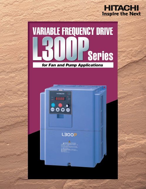
quency Drive DeliversFan and Pump Applications!FOR OPTIMAL OPERATIONFOR OPTIMAL OPERATIONHighperformanceCONTENTSFEATURESSTANDARD SPECIFICATIONSDIMENSIONSPAGE1 - 45 - 78 - 11EasyMaintenanceGlobalStandardsHitachiInverter<strong>L300P</strong>Ease ofOperationCompactSizeOPERATION and PROGRAMMINGFUNCTION LISTTERMINALSPROTECTIVE FUNCTIONS1213 - 1617 - 1819CONNECTING DIAGRAM20 - 21CONNECTING TO PLC22WIRING and ACCESSORIES23ACCESSORIES24 - 26FOR COMPACT PANEL27TORQUE CHARACTERISTICS, DERATING DATA28FOR CORRECT OPERATION29 - 30ISO 14001EC97J1095ISO 9001JQA-1153Hitachi variable frequencydrives (inverters) in thisbrochure are produced at thefactory registered under theISO 14001 standard forenvironmental managementsystem and the ISO 9001standard for inverter qualitymanagement system.2
EASY-REMOVABLECOOLING FANAND DC BUS CAPACITORCooling fan(s) and DC buscapaci-tors can be easilychanged in the field. Afan ON/OFF function canbe activated to providelonger cooling fan life.REMOVABLE CONTROLCIRCUIT TERMINALSEliminates control rewiring when field replacing the <strong>L300P</strong>.Control Circuit TerminalsThe <strong>L300P</strong>’s compact size helps economize panel space.Installation area is reduced by approximately 30% fromthat of our previous series.(Comparison of 11kW (15HP))EASE OF OPERATION WITHDIGITAL OPERATOR (OPE-SR)Output frequency can be controlled by the integralpotentiometer provided as standard on the OPE-SR.The OPE-SR can be removed for remote control, and hasan easy-to-see 4-digit display and LEDs to indicate theunit being monitored (i.e. frequency, amps, power, etc.).A multilingual operator (English, French, German, Italian,Spanish, and Portuguese) with copy function (SRW-0EX) and a digital operator without potentiometer (OPE-S) are also available as options.BUILT-IN RS485RS485 is provided as standard for ASCII serialcommunication.PROGRAMMING SOFTWAREOptional PC drive configuration software which runs onWindows ® Operating System.3USER SELECTION OFCOMMAND FUNCTIONS(“Quick Menu”)You can select frequently used commands and storethem for fast reference.
EMI FILTEREMI filters to meet European EMC (EN61800-3, EN55011)and low-voltage directive (EN50178) are available for systemconformance.REDUCED NOISE FROM MAINCIRCUIT POWER SUPPLY ANDCONTROL CIRCUIT POWER SUPPLYDisturbance voltage of the main circuit power supply andof the control circuit power supply has been improved byapproximately 15dB( V) and 20dB( V) respectively comparedto our previous model(J300), resulting in significant reductionsto noise interference with sensors and other peripheraldevices.Disturbance voltage of the main circuit power supply(It does not comply with European EMC directive. To meet the EMC directive,please use an EMI filter.)Disturbance voltage [dB(µV)]10090807060400 .2 .3 .5 .7 1 5 7 10 20 30Frequency(MHz)Disturbance voltage of the control circuit power supply(Disturbance voltage of terminal L or CM1)Disturbance voltage [dB(µV)]10080604020J300-220LFU<strong>L300P</strong>-220LFU2J300-055LFU<strong>L300P</strong>-055LFU2HARMONICS MITIGATIONJ300 series<strong>L300P</strong> seriesJ300 series<strong>L300P</strong> series0 .2 .3 .5 .7 1 3 5 7 10 20 30Frequency(MHz)Terminals for the connection of a DC Reactor are providedas standard for harmonics suppression.CONTROL OF VOLTAGE OFMICRO SERGESuppressing the motor terminal voltage less than 2xE [V]by improving the control method of PWM output.Input voltage:400VAC(In the case)Motor terminal voltage:1,131V(400VX2X2IMPROVEMENT OF ENVIRONMENTThe printed circuit board inside an inverter is varnishcoating specification as standard.Standard enclosure protection for the <strong>L300P</strong> is IP20 (NEMA1*).For IP54 (NEMA12), please contact Hitachi sales office.*NEMA 1 applies up to 30kW. An optional wire-entry conduit box is required for 37kW to75kW models to meet NEMA 1 rating.CONFORMITY TO GLOBALSTANDARDSCE, UL, c-UL, C-Tick approvals.NETWORK COMPATIBILITYThe <strong>L300P</strong> can communicate with DeviceNet,PROFIBUS®, LONWORKS®, Modbus® RTU *1 ,and Ethernet *2 with communication options.*1, *2: Being plannedMODEL NAME INDICATIONSeries Name<strong>L300P</strong> - 015 L F U 2Applicable Motor CapacityPower SourceL:3-phase 200V ClassH:3-phase 400V ClassF:With Digital OperatorMODEL CONFIGURATIONVersion numberU:UL version for North AmericaE:CE version for EuropeApplicable Motor Capacityin kW (HP) 3-phase 200V class 3-phase 400V class1.5(2) <strong>L300P</strong>-015LFU2 <strong>L300P</strong>-015HFU2/E22.2(3) <strong>L300P</strong>-022LFU2 <strong>L300P</strong>-022HFU2/E23.7(5) <strong>L300P</strong>-037LFU2 <strong>L300P</strong>-040HFU2/E25.5(7.5) <strong>L300P</strong>-055LFU2 <strong>L300P</strong>-055HFU2/E27.5(10) <strong>L300P</strong>-075LFU2 <strong>L300P</strong>-075HFU2/E211(15) <strong>L300P</strong>-110LFU2 <strong>L300P</strong>-110HFU2/E215(20) <strong>L300P</strong>-150LFU2 <strong>L300P</strong>-150HFU2/E218.5(25) <strong>L300P</strong>-185LFU2 <strong>L300P</strong>-185HFU2/E222(30) <strong>L300P</strong>-220LFU2 <strong>L300P</strong>-220HFU2/E230(40) <strong>L300P</strong>-300LFU2 <strong>L300P</strong>-300HFU2/E237(50) <strong>L300P</strong>-370LFU2 <strong>L300P</strong>-370HFU2/E245(60) <strong>L300P</strong>-450LFU2 <strong>L300P</strong>-450HFU2/E255(75)<strong>L300P</strong>-550LFU2<strong>L300P</strong>-550HFU2/E275(100) <strong>L300P</strong>-750LFU2 <strong>L300P</strong>-750HFU2/E290(125) <strong>L300P</strong>-900HFU2/E2110(150) <strong>L300P</strong>-1100HFU2/E2132(175) <strong>L300P</strong>-1320HFU2/E2Windows is a registered trademark of Microsoft Corp. in the U.S. and other countries.DeviceNet is a trademark of Open DeviceNet Vendor Association.PROFIBUS is a registered trademark of Profibus Nutzer Organization.4
STANDARD SPECIFICATIONSModelUL version<strong>L300P</strong>-XXX CE versionEnclosure (* 2)Applicable motor (4-pole, kW(HP)) (* 3)Rated capacity 200V(kVA)240VRated input voltageRated input current (A)Required power supply capacity (kVA)Rated output voltage (* 4)Rated output current (continuous)(A)Control methodOutput frequency range (* 5)Frequency accuracyFrequency resolutionV/f characteristicsOverload capacityAcceleration/deceleration timeDynamic braking(Short-time)Braking(* 6)DC brakingInputsignalIntelligentinput terminals(Assign five functionsto terminals)Thermistor inputIntelligent outputOutput terminalssignal Intelligent monitoroutput terminalsDisplay monitorOther user-settable parametersCarrier frequency rangeProtective functionsEnvironmentalconditionsColorOptionsItemFrequencysettingForward/reverseStart/stopOperatorPotentiometerExternal signalExternal portOperatorExternal signalExternal portAmbient operating /storagetemperature(* 7)/humidityVibration (* 8)Location015LFU2—1.5(2)2.53.18.337.5022LFU2—2.2(3)3.64.3124.4037LFU2—3.7(5)5.76.8187.4055LFU2—075LFU2—200V Class110LFU2—150LFU2—185LFU2—IP20 (NEMA 1) (* 1)11(15)15.218.215(20)20.024.118.5(25)25.230.3220LFU2—300LFU2—370LFU2—5.5(7.5) 7.5(10)22(30) 30(40) 37(50)8.3 1129.4 39.1 48.49.9 13.335.3 46.9 58.13-phase (3-wire) 200-240V (±10%), 50/60Hz26113515482264308037944412460154743-phase (3-wire) 200-240V (Corresponding to input voltage)24 32 44 58 73 85 113 140450LFU2—45(60)58.570.218690550LFU2—10.5 16.5169 210Line to line sine wave PWM0.1-400HzDigital: ±0.01% of the maximum frequency, Analog: ±0.2%(25±10°C)Digital setting: 0.01Hz, Analog setting: (Maximum frequency)/4,000 (O terminal: 12-bit 0–10V, O2 terminal: 12-bit-10–+10V)V/f optionally variable, V/f control (Constant torque, reduced torque)120% for 60sec., 150% for 0.5sec.0.01-3,600sec. (Linear/curve, accel./decel. selection), Two-stage accel./decel.Built-in BRD circuit(optional resistor)Performs at start; under set frequency at deceleration, or via an external input(braking force, time, and operating frequency).Up and Down keysPotentiometerDC 0-10V, –10-+10V (input impedance 10k ), 4-20mA (input impedance 100 )RS-485 interfaceRun key/Stop key (FW/RV can be set by function command.)FW RUN/STOP (NO contact), RV set by terminal assignment (NO/NC selection), 3-wire input availableSet by RS-48555(75)72.787.2231110External dynamic braking unit (option)RV(Reverse), CF1-CF4(Multispeed command), JG(Jogging), DB(External DC braking),SET(Second motor constants setting), 2CH(Second accel./decel.), FRS(Free-run stop), EXT(External trip),USP(Unattended start protection), CS(Change to/from commercial power supply),SFT(Software lock),AT(Analog input selection), RS(Reset), STA(3-wire start), STP(3-wire stop), F/R(3-wire fwd./rev.), PID(PID On/Off),PIDC(PID reset), UP/DWN(Remote-controlled accel./decel.) UDC(Remote-controlled data clearing),SF1-SF7(Multispeed bit command 1-7), OLR(Overload limit change), ROK(RUN Permissive) and NO(Not selected)One terminal(PTC)Assign three functions to two NO contacts and one NO-NC combined contact(RUN, FA1, FA2, OL, OD, AL, FA3, IP, UV, RNT, ONT RMD and THM)Analog voltage, analog current, PWM outputOutput frequency, output current, scaled value of output frequency, trip history, I/O terminal condition, input power, output voltageV/f free-setting (up to 7 points), frequency upper/lower limit, frequency jump, accel./decel. curve selection, manualtorque boost value and frequency adjustment, analog meter tuning, starting frequency, carrier frequency, electronic thermalprotection level, external frequency output zero/span reference, external frequency input bias start/end, analog inputselection, retry after trip, reduced voltage soft start, overload restriction, automatic energy-saving0.5-12kHzOver-current protection, overload protection, braking resistor overload protection, over-voltage protection, EEPROMerror, under-voltage error, CT(Current transformer) error, CPU error, external trip, USP error, ground fault, input overvoltageprotection, instantaneous power failure, option 1 connection error, option 2 connection error, inverter thermaltrip, phase failure detection, IGBT error, thermistor error–10-40°C(* 9) / –20-65°C / 25-90%RH (No condensation)EMI filters, input/output reactors, DC reactors, radio noise filters, braking resistors, braking units, LCR filter, communicationcables, Network interface cards750LFU2—75(100)93.5112.25.9m/s 2 (0.6G), 10-55Hz2.9m/s 2 (0.3G), 10-55HzAltitude 1,000m or less, indoors (no corrosive gases or dust)BlueGray (Bezel for digital operator is blue)2971502705OperatorWeight kg (lbs.)* 1: Up to 30kW.An optional conduit box is required for 37kW to 55kW to meet NEMA 1 .* 2: The protection method conforms to JEM 1030 / NEMA(U.S.).The applicable motor refers to Hitachi standard 3-phase motor (4-pole).To use other motors, care must be taken to prevent the rated motor current(50Hz) from exceeding the rated output current of the inverter.* 3: * 4:OPE-SR(4-digit LED with potentiometer) / OPE-SRE(4-digit LED with potentiometer, English overlay)Optional: OPE-S(4-digit LED), SRW-0EX(Multilingual (English,French, German, Italian, Spanish, and Portuguese)operator with copy function), ICS-1,3(Cable for operators(1m, 3m))3.5 (7.7) 3.5 (7.7) 3.5 (7.7) 3.5 (7.7) 5 (11)5 (11)5 (11)12 (26.4)The output voltage decreases as the main power supply voltage decreasesexcept for the use of AVR function.* 5: To operate the motor beyond 50/60Hz, please consult with the motormanufacturer about the maximum allowable rotation speed.Braking resistor is not integrated in the inverter. Please install optionalbraking resistor or dynamic braking unit when large braking torque isrequired.12 (26.4)* 6: * 7:12 (26.4)20 (44)30 (66)30 (66)50 (110)Storage temperature refers to the temperature in transportation.8: Conforms to the test method specified in JIS C0040(1999).* 9: When using the inverter from 40º to 50ºC ambient, the output current ofthe inverter must be derated (see the next section on derating curves).
ModelUL version<strong>L300P</strong>-XXX CE versionEnclosure (* 2)Applicable motor (4-pole, kW(HP)) (* 3)Rated capacity 400V(kVA)480VRated input voltageRated input current (A)Required power supply capacity (kVA)Rated output voltage (* 4)Rated output current (continuous)(A)Control methodOutput frequency range (* 5)Frequency accuracyFrequency resolutionV/f characteristicsOverload capacityAcceleration/deceleration timeDynamic braking(Short-time)Braking(* 6)DC brakingInputsignalIntelligentinput terminals(Assign five functionsto terminals)Thermistor inputIntelligent outputOutput terminalssignal Intelligent monitoroutput terminalsDisplay monitorOther user-settable parametersCarrier frequency rangeProtective functionsEnvironmentalconditionsColorOptionsItemFrequencysettingForward/reverseStart/stopOperatorPotentiometerExternal signalExternal portOperatorExternal signalExternal portAmbient operating /storagetemperature(* 7)/humidityVibration (* 8)Location015HFU2015HFE21.5(2)2.63.14.233.8022HFU2022HFE22.2(3)3.64.4040HFU2040HFE24.0(5)5.97.1055HFU2055HFE25.5(7.5)8.3400V Class075HFU2 110HFU2075HFE2 110HFE2IP20 (NEMA 1) (* 1)7.5(10) 11(15)11 15.213.3 18.2185HFU2185HFE218.5(25)25.630.7220HFU2220HFE222(30)29.735.79.924.13-phase (3-wire) 380-480V (±10%), 50/60Hz5.8 9.5 13 18 24 32 41 474.4 8 11 15 22 30 37 443-phase (3-wire) 380-480V (Corresponding to input voltage)5.3 8.6 12 16 22 29 37 43Line to line sine wave PWM0.1-400HzDigital: ±0.01% of the maximum frequency, Analog: ±0.2%(25±10°C)Digital setting: 0.01Hz, Analog setting: (Maximum frequency)/4,000 (O terminal: 12-bit 0–10V, O2 terminal: 12-bit-10–+10V)V/f optionally variable, V/f control (Constant torque, reduced torque)120% for 60sec., 150% for 0.5sec.0.01-3,600sec. (Linear/curve, accel./decel. selection), Two-stage accel./decel.Built-in BRD circuit(optional resistor)Performs at start; under set frequency at deceleration, or via an external input(braking force, time, and operating frequency).Up and Down keysPotentiometerDC 0-10V, –10-+10V (input impedance 10k ), 4-20mA (input impedance 100 )RS-485 interfaceRun key/Stop key (FW/RV can be set by function command.)FW RUN/STOP (NO contact), RV set by terminal assignment (NO/NC selection), 3-wire input availableSet by RS-485300HFU2300HFE230(40)39.447.3636057External dynamic braking unit(option)RV(Reverse), CF1-CF4(Multispeed command), JG(Jogging), DB(External DC braking),SET(Second motor constants setting), 2CH(Second accel./decel.), FRS(Free-run stop), EXT(External trip),USP(Unattended start protection), CS(Change to/from commercial power supply),SFT(Software lock),AT(Analog input selection), RS(Reset), STA(3-wire start), STP(3-wire stop), F/R(3-wire fwd./rev.), PID(PID On/Off),PIDC(PID reset), UP/DWN(Remote-controlled accel./decel.) UDC(Remote-controlled data clearing),SF1-SF7(Multispeed bit command 1-7), OLR(Overload limit change), ROK(RUN Permissive) and NO(Not selected)One terminal(PTC)Assign three functions to two NO contacts and one NO-NC combined contact(RUN, FA1, FA2, OL, OD, AL, FA3, IP, UV, RNT, ONT RMD and THM)Analog voltage, analog current, PWM outputOutput frequency, output current, scaled value of output frequency, trip history, I/O terminal condition, input power, output voltageV/f free-setting (up to 7 points), frequency upper/lower limit, frequency jump, accel./decel. curve selection, manualtorque boost value and frequency adjustment, analog meter tuning, starting frequency, carrier frequency, electronic thermalprotection level, external frequency output zero/span reference, external frequency input bias start/end, analog inputselection, retry after trip, reduced voltage soft start, overload restriction, automatic energy-saving0.5-12kHz150HFU2150HFE215(20)20.0Over-current protection, overload protection, braking resistor overload protection, over-voltage protection, EEPROMerror, under-voltage error, CT(Current transformer) error, CPU error, external trip, USP error, ground fault, input overvoltageprotection, instantaneous power failure, option 1 connection error, option 2 connection error, inverter thermaltrip, phase failure detection, IGBT error, thermistor error–10-40°C(* 9) / –20-65°C / 25-90%RH (No condensation)5.9m/s 2 (0.6G), 10-55HzAltitude 1,000m or less, indoors (no corrosive gases or dust)BlueEMI filters, input/output reactors, DC reactors, radio noise filters, braking resistors, braking units, LCR filter, communicationcables, Network interface cardsOperatorWeight kg (lbs.)* 1: Up to 30kW.An optional conduit box is required for 37kW to 55kW to meet NEMA 1 .* 2: The protection method conforms to JEM 1030 / NEMA(U.S.).The applicable motor refers to Hitachi standard 3-phase motor (4-pole).To use other motors, care must be taken to prevent the rated motor current(50Hz) from exceeding the rated output current of the inverter.* 3: * 4:OPE-SR(4-digit LED with potentiometer) / OPE-SRE(4-digit LED with potentiometer, English overlay)Optional: OPE-S(4-digit LED), SRW-0EX(Multilingual (English,French, German, Italian, Spanish, and Portuguese)operator with copy function), ICS-1,3(Cable for operators(1m, 3m))3.5 (7.7) 3.5 (7.7) 3.5 (7.7) 3.5 (7.7) 5 (11)5 (11)The output voltage decreases as the main power supply voltage decreasesexcept for the use of AVR function.* 5: To operate the motor beyond 50/60Hz, please consult with the motormanufacturer about the maximum allowable rotation speed.Braking resistor is not integrated in the inverter. Please install optionalbraking resistor or dynamic braking unit when large braking torque isrequired.* 6: * 7:5 (11)12 (26.4)12 (26.4)12 (26.4)Storage temperature refers to the temperature in transportation.8: Conforms to the test method specified in JIS C0040(1999).* 9: When using the inverter from 40º to 50ºC ambient, the output current ofthe inverter must be derated (see the next section on derating curves).6
STANDARD SPECIFICATIONSModelUL version<strong>L300P</strong>-XXX CE versionEnclosure (* 2)Applicable motor (4-pole, kW(HP)) (* 3)Rated capacity 400V(kVA)480VRated input voltageRated input current (A)Required power supply capacity (kVA)Rated output voltage (* 4)Rated output current (continuous)(A)Control methodOutput frequency range (* 5)Frequency accuracyFrequency resolutionV/f characteristicsOverload capacityAcceleration/deceleration timeDynamic braking(Short-time)Braking(* 6)DC brakingInputsignalIntelligentinput terminals(Assign five functionsto terminals)Thermistor inputIntelligent outputOutput terminalssignal Intelligent monitoroutput terminalsDisplay monitorOther user-settable parametersCarrier frequency rangeProtective functionsEnvironmentalconditionsColorOptionsItemFrequencysettingForward/reverseStart/stopOperatorPotentiometerExternal signalExternal portOperatorExternal signalExternal portAmbient operating /storagetemperature(* 7)/humidityVibration (* 8)Location370HFU2370HFE237(50)48.458.1777470450HFU2 550HFU2450HFE2 550HFE2IP20 (NEMA 1) (* 1)45(60)55(75)58.872.770.187.2400V Class750HFU2750HFE275(100) 90 (125) 110 (150)93.5110.8135.0112.2133.0162.13-phase (3-wire) 380-480V (±10%), 50/60Hz94901161101491501761802152203-phase (3-wire) 380-480V (Corresponding to input voltage)85105135160195Line to line sine wave PWM0.1-400HzDigital: ±0.01% of the maximum frequency, Analog: ±0.2%(25±10°C)Digital setting: 0.01Hz, Analog setting: (Maximum frequency)/4,000 (O terminal: 12-bit 0–10V, O2 terminal: 12-bit-10–+10V)V/f optionally variable, V/f control (Constant torque, reduced torque)120% for 60sec., 150% for 0.5sec.0.01-3,600sec. (Linear/curve, accel./decel. selection), Two-stage accel./decel.External dynamic braking unit (option)Performs at start; under set frequency at deceleration, or via an external input(braking force, time, and operating frequency).Up and Down keysPotentiometerDC 0-10V, –10-+10V (input impedance 10k ), 4-20mA (input impedance 100 )RS-485 interfaceRun key/Stop key (FW/RV can be set by function command.)FW RUN/STOP (NO contact), RV set by terminal assignment (NO/NC selection), 3-wire input availableSet by RS-485RV(Reverse), CF1-CF4(Multispeed command), JG(Jogging), DB(External DC braking),SET(Second motor constants setting), 2CH(Second accel./decel.), FRS(Free-run stop), EXT(External trip),USP(Unattended start protection), CS(Change to/from commercial power supply),SFT(Software lock),AT(Analog input selection), RS(Reset), STA(3-wire start), STP(3-wire stop), F/R(3-wire fwd./rev.), PID(PID On/Off),PIDC(PID reset), UP/DWN(Remote-controlled accel./decel.) UDC(Remote-controlled data clearing),SF1-SF7(Multispeed bit command 1-7), OLR(Overload limit change), ROK(RUN Permission) and NO(Not selected)One terminal(PTC)900HFU2900HFE2Assign three functions to two NO contacts and one NO-NC combined contact(RUN, FA1, FA2, OL, OD, AL, FA3, IP, UV, RNT, ONT, RMD and THM)Analog voltage, analog current, PWM outputOutput frequency, output current, scaled value of output frequency, trip history, I/O terminal condition, input power, output voltageV/f free-setting (up to 7 points), frequency upper/lower limit, frequency jump, accel./decel. curve selection, manualtorque boost value and frequency adjustment, analog meter tuning, starting frequency, carrier frequency, electronic thermalprotection level, external frequency output zero/span reference, external frequency input bias start/end, analog inputselection, retry after trip, reduced voltage soft start, overload restriction, automatic energy-saving0.5-12kHzOver-current protection, overload protection, braking resistor overload protection, over-voltage protection, EEPROMerror, under-voltage error, CT(Current transformer) error, CPU error, external trip, USP error, ground fault, input overvoltageprotection, instantaneous power failure, option 1 connection error, option 2 connection error, inverter thermaltrip, phase failure detection, IGBT error, thermistor error–10-40°C(* 9) / –20-65°C / 25-90%RH (No condensation)2.9m/s 2 (0.3G), 10-55HzAltitude 1,000m or less, indoors (no corrosive gases or dust)Gray (Bezel for digital operator is blue)1100HFU21100HFE2IP000.5-8kHzEMI filters, input/output reactors, DC reactors, radio noise filters, braking resistors,braking units, LCR filter, communication cables, Network interface cards1320HFU21320HFE2132 (175)159.3191.22532642307OperatorWeight kg (lbs.)* 1: Up to 30kW.An optional conduit box is required for 37kW to 55kW to meet NEMA 1 .* 2: The protection method conforms to JEM 1030 / NEMA(U.S.).The applicable motor refers to Hitachi standard 3-phase motor (4-pole).To use other motors, care must be taken to prevent the rated motor current(50Hz) from exceeding the rated output current of the inverter.* 3: * 4:OPE-SR(4-digit LED with potentiometer) / OPE-SRE(4-digit LED with potentiometer, English overlay)Optional: OPE-S(4-digit LED), SRW-0EX(Multilingual (English,French, German, Italian, Spanish, and Portuguese)operator with copy function), ICS-1,3(Cable for operators(1m, 3m))20 (44) 30 (66) 30 (66) 30 (66) 60 (132) 60 (132) 80 (176)The output voltage decreases as the main power supply voltage decreasesexcept for the use of AVR function.* 5: To operate the motor beyond 50/60Hz, please consult with the motormanufacturer about the maximum allowable rotation speed.Braking resistor is not integrated in the inverter. Please install optionalbraking resistor or dynamic braking unit when large braking torque isrequired.* 6: * 7:Storage temperature refers to the temperature in transportation.8: Conforms to the test method specified in JIS C0040(1999).* 9: When using the inverter from 40º to 50ºC ambient, the output current ofthe inverter must be derated (see the next section on derating curves).
DIMENSIONS<strong>L300P</strong>-015-055LFU2015-055HFU2015-055HFE225(0.98)150(5.91)130(5.12)80(3.15)Digital Operator2- 6 ( 0.24)Exhaust[Unit:mm (inch)]Inches for reference only164(6.46) 79(3.11)241(9.49)255(10.04)Wall6(0.24)130(5.12)3- 20( 0.78)Wiring Hole40(1.57)Air intake75(2.95)LFU2HFU2 type(055LFU2HFU2)Conduit box to meet NEMA1 rating<strong>L300P</strong>-075-150LFU2, 075-150HFE2, 075-150HFU2[Unit:mm (inch)]Inches for reference only24.5(0.97)210(8.27)189(7.44)80(3.15)Digital Operator2- 7( 0.28)Exhaust170(6.69)79(3.11)Wall7(0.28)189(7.44)70(2.76)Air intake80(3.15)LFU2HFU2 typeConduit box to meet NEMA1 rating82(3.23)246(9.69)260(10.24)7(0.28)8.5(0.33)69(2.72)140(5.51)143(5.63)7(0.28)8.5(0.33)170(6.69)3- 25( 0.98)Wiring hole203(7.99)8
DIMENSIONS<strong>L300P</strong>-185-300LFU2,185-300HFE2,185-300HFU224.5(0.97)250(9.84)229(9.02)80(3.15)Digital Operator2- 7( 0.28)Exhaust[Unit:mm (inch)]Inches for reference only79(3.11)273(10.75)376(14.80)390(15.35)Wall7(0.28)229(9.02)8.5(0.33)147(5.79)Air intake9.5(0.37)83(3.27)190(7.48)4- 29.5( 1.16)Wiring hole104(4.09)LFU2HFU2 typeConduit box to meet NEMA1 rating244(9.61)<strong>L300P</strong>-370LFU2,370HFE2,370HFU245(1.77) 80(3.15)Digital Operator2- 10 ( 0.39)Exhaust[Unit:mm (inch)]Inches for reference only79(3.11)510 (20.08)540 (21.26)2-10(0.39)265(10.43)310(12.20)195(7.68)Wall271(10.67)8.5(0.33)145(5.71)175(6.89)Air intake74(2.91)Conduit box to meet NEMA1 rating (Optional)9
<strong>L300P</strong>-450-550LFU2,450-750HFE2,450-750HFU232.5(1.28) 80(3.15)Digital Operator2- 12( 0.47)Exhaust[Unit:mm (inch)]Inches for reference only<strong>L300P</strong>-750LFU22 12(0.47 )520(20.47)550(21.65)Wall2-12(0.47)300(11.81)390(15.35)8.5(0.33)277(10.91)155(6.01)185(7.28)250 (9.84)79(3.11)Air intake90(3.54)Conduit box to meet NEMA1 rating (Optional)125(4.92) 80(3.15)Digital OperatorExhaust[Unit:mm (inch)]Inches for reference only79(3.11)670(26.38)700(27.56)Wall352(13.87)2-12 (0.47)380(14.96)480(18.90)160(6.30)8.5(0.33)190(7.48)104(4.09)Air intake250 (9.84)Conduit box to meet NEMA 1 rating(Optional)10
DIMENSIONS<strong>L300P</strong>-900HFE2, HFU2-1100HFE2, HFU232.5(1.28)80(3.15)Digital Operator2- 12( 0.47)Exhaust[Unit:mm (inch)]Inches for reference only79(3.11)670(26.38)700(27.56)Wall2-12(0.47)300(11.81)390(15.35)Air intake<strong>L300P</strong>-1320HFE2, HFU2Exhaust710 (27.95)740 (29.13)Wall2-12 (0.47)8.5 (0.33)Air intake270 (10.63)270(10.63)357(14.06)8.5(0.33)62.5(2.46) 80(3.15)Digital Operator2 12(0.47 )[Unit:mm (inch)]Inches for reference only480(18.91)79(3.11)380 (14.76)480 (18.90)11
OPERATION and PROGRAMMING<strong>L300P</strong> Series can be easily operated with the digital operator (OPE-SR) provided as standard. The Digital operator canalso be detached and used for remote-control. A multilingual (English, French, German Italian, Spanish, and Portuguese)operator with copy function (SRW-0EX) or a digital operator without potentiometer(OPE-S) is also available as an option.(For US version, OPE-SRE (English overlay with potentiometer) is provided as standard.)Parameter DisplayDisplays frequency, motor current,rotational speed of themotor, and an alarm code.Monitor LEDsShows drive's status.RUN KeyPress to run the motor.STOP/RESET KeyPress to stop the drive orreset an alarm.Function KeyPress to set or monitor aparameter value.Power LEDLights when the power input tothe drive is ON.Display Unit LEDsIndicates the unit associatedwith the parameter display.PotentiometerStore KeyPress to write the new value tothe EEPROM.Up/Down KeysPress up or down to sequence throughparameters and functions shown on thedisplay, and increment/decrement values.1. Setting the maximum output frequency(1) or the value previouslymonitored is displayed.(2)Function code appears. (3) appears.(4) or the codenumber set in the end oflast setting is displayed.POWERPOWERPOWERPOWERALARMALARMALARMALARMPoweronRUNPRGFUNCHzVkWA%MIN MAXSTRHzHzRUNRUNVVkWkWPRGAPRGA%%Press FUNC key. MIN MAXMIN MAX Press FUNC key.FUNCPressuntilHzRUNVkWPRGA%MIN MAXSTR FUNCSTR FUNC STRappears.(5) appears. (6)Preset value is displayed. (7)Newly set value is displayed.(8)Returns to andthe setting is complete.POWERPOWERPOWERPOWERALARMALARMALARMALARMRUNPRGHzVkWA%RUNPRGHzVkWA%RUNPRGHzVkWA%RUNPRGHzVkWA%Pressuntilappears.FUNCMIN MAXSTRPress FUNC key.2. Running the motor(by potentiometer)FUNCMIN MAXSTRPressto set desired value.FUNCMIN MAXSTRPress STR keyto store the value.FUNCMIN MAXSTR*To run the motor, goback to monitor modeor basic setting mode.(1) or the value previouslymonitored is displayed.(2)The motor runs at the frequencyset by the potentiometer.(3)The motor stops.POWERPOWERPOWERALARMALARMALARMPoweronRUNPRGFUNCMIN MAXSTR3. Monitoring output current value(1) or the value previouslymonitored is displayed.HzVA%kWPress RUN key and turn thepotentiometer clockwise.RUNPRGMIN MAXMIN MAXFUNC STR FUNC STR(Output frequency monitor)HzVA%kWPressSTOPRESET(2)Function code appears. (3) appears.key to stop the motor.RUNPRG(4)Output current valueis displayed.HzVA%kWPOWERPOWERPOWERPOWERALARMALARMALARMALARMPoweronRUNPRGFUNCHzVkWA%MIN MAXSTRHzHzRUNRUNVVkWkWPRGAPRGA%%Press FUNC key. MIN MAXMIN MAX Press FUNC key.FUNCSTRPressuntil appears.FUNCSTRRUNPRGFUNCHzVkWA%MIN MAXSTR12
Coded001d002d003d004d005FUNCTION LISTMonitoring Functions and Main Profile ParametersNameOutput frequency monitorOutput current monitorMotor rotational direction monitorProcess variable (PV), PID feedback monitorIntelligent input terminal statusDescription0.00-99.99/100.0-400.0Hz0.0-999.9AF(Forward) / o(Stop) / r(Reverse)0.00-99.99/100.0-999.9/1000.-9999./1000-9999/ 100- 999(10,000-99,900)FWON (Example) Terminal FW, 2 and 1 : ONOFFTerminal 5, 4, and 3 : OFF5 4 32 1Default Setting-FE(CE) -FU2(UL)––––––––––= Allowed[ = Not permitted]Run-timeSetting–––––Run-time Data Edit(Enabled at b031)–––––Expanded Function Setting ModeMonitor Moded006d007d013d014d016d017d080d081d086d090F001F002F202F003F203F004A---b---C---H---P---U---Intelligent output terminal statusScaled output frequency monitorOutput voltage monitorPower monitorCumulative RUN time monitorCumulative power-on time monitorTrip count monitorTrip monitor 1-6Warning monitorOutput frequency settingAcceleration time (1) settingAcceleration time (1) setting for second motorDeceleration time (1) settingDeceleration time (1) setting for second motorMotor rotational direction settingA Group: Standard functionsb Group: Fine tuning functionsC Group: Intelligent terminal functionsH Group: Motor constants functionsP Group: Expansion card functionsU Group: User-selectable menu functionsON (Example) Terminal 12 and 11 : ONOFFAL :OFFAL 12 110.00-99.99/100.0-999.9/1000.-9999./1000-3996(10,000-39,960)0.0-600.0V0.0-999.9kW0.-9999./1000-9999/ 100- 999 (10,000-99,900)hr0.-9999./1000-9999/ 100- 999 (10,000-99,900)hr0.-9999./1000-6553(10,000-65,530)Displays trip event informationWarning code0.0, Starting frequency to maximum frequency / maximum frequency for second motor0.01-99.99/100.0-999.9/1000.-3600. sec.0.01-99.99/100.0-999.9/1000.-3600. sec.0.01-99.99/100.0-999.9/1000.-3600. sec.0.01-99.99/100.0-999.9/1000.-3600. sec.00(Forward) / 01 (Reverse)–––––––––0.00Hz30.00s30.00s30.00s30.00s00–––––––––0.00Hz60.00s60.00s60.00s60.00s00––––––––––––––––––Basic SettingAnalog Input SettingMultispeed and Jogging Frequency SettingA Group: Standard FunctionsCodeA001A002A003A203A004A204A005A006A011A012A013A014A015A016A019A020A220A021IA035A038A039NameFrequency source settingRun command source settingBase frequency settingBase frequency setting for second motorMaximum frequency settingMaximum frequency setting for second settingAT selectionO2 selectionO-L input active range start frequencyO-L input active range end frequencyO-L input active range start voltageO-L input active range end voltageO-L input start frequency enableExternal frequency filter time constantMultispeed operation selectionMultispeed frequency setting (0)Multispeed frequency setting (0) for second motorMultispeed frequency setting (1-15)Jog frequency settingJog stop modeDescription00(Potentiometer) / 01(Terminals) / 02(Operator) / 03(RS485) / 04 (Expansion card 1) / 05(Expansion card 2)01(Terminals) / 02(Operator) / 03(RS485) / 04 (Expansion card 1) / 05(Expansion card 2)30.00Hz-Maximum frequency30.00Hz-Maximum frequency for second motor30.00-400.0Hz30.00-400.0Hz00(Selection between O and OI at AT) / 01(Selection between O and O2 at AT)00(Independent) / 01(Only positive) / 02(Both positive and negative)0.00-400.0Hz0.00-400.0Hz0.-100.%0.-100.%00(External frequency output zero reference) / 01(0Hz)1.-30. (Sampling time = 2 msec.)00(Binary: up to 16-stage speed at 4 terminals) / 01(Bit: up to 6-stage speed at 5 terminals)0.00, Starting frequency to maximum frequency0.00, Starting frequency to maximum frequency for second motor0.00, Starting frequency to maximum frequency0.00, Starting frequency to 9.99Hz00(Free-run stop/disable during RUN) / 01(Deceleration to stop/ disable during RUN) /02(DC braking to stop/ disable during RUN) / 03(Free-run stop/ enable during RUN) /04(Deceleration to stop/ enable during RUN) / 05(DC braking to stop/ enable duringRUN)Default Setting-FE(CE) -FU2(UL)010150.50.50.50.00000.000.000.100.018.000.000.000.001.0000010160.60.60.60.00000.0060.000.100.018.000.000.000.001.0000= Allowed[ = Not permitted]Run-timeSettingRun-time Data Edit(Enabled at b031)13
CodeV/fCharacteristicDC BrakingUpper/LowerLimit andJumpFrequencyPID ControlAVRFunctionOperationMode andAccel./Decel.FunctionExternalFrequencyTuningAccel./Decel.CurveA041A241A042A242A043A243A044A244A045A051A052A053A054A055A056A057A058A059A061A261A062A262A063A064A065A066A067A068A069A070A071A072A073A074A075A076A081A082A085A086A092A292A093A293A094A294A095A295A096A296A097A098A101A102A103A104A105A111A112A113A114A131A132( *1) 90kW and overNameTorque boost method selectionTorque boost method selection for second motorManual torque boost valueManual torque boost value for second motorManual torque boost frequency adjustmentManual torque boost frequency adjustment for second motorV/f characteristic curve selectionV/f characteristic curve selection for second motorV/f gain settingDC braking enableDC braking frequency settingDC braking wait timeDC braking force settingDC braking time settingDC braking edge or level detectionDC braking force setting at the starting pointDC braking time setting at the starting pointDC braking carrier frequency settingFrequency upper limit settingFrequency upper limit setting for second motorFrequency lower limit settingFrequency lower limit setting for second motorJump frequency (1) settingJump frequency width (1) settingJump frequency (2) settingJump frequency width (2) settingJump frequency (3) settingJump frequency width (3) settingAcceleration hold frequency settingAcceleration stop time settingPID function enablePID proportional gainPID integral gainPID differential gainProcess variable scale conversionProcess variable source settingAVR function selectionAVR voltage selectionOperation mode selectionEnergy saving mode tuningAcceleration time (2)Acceleration time (2) for second motorDeceleration time (2)Deceleration time (2) for second motorSelect method to switch to second accel./ decel. profileSelect method to switch to second accel./ decel. profile for second motorAccel(1) to Accel(2) frequency transition pointAccel(1) to Accel(2) frequency transition point for second motorDecel(1) to Decel(2) frequency transition pointDecel(1) to Decel(2) frequency transition point for second motorAcceleration curve selectionDeceleration curve selectionOI-L input active range start frequencyOI-L input active range end frequencyOI-L input active range start voltageOI-L input active range end voltageOI-L input start frequency enableO2-L input active range start frequencyO2-L input active range end frequencyO2-L input active range start voltageO2-L input active range end voltageAcceleration curve constants settingDeceleration curve constants settingDescription00(Manual torque boost) / 01(Automatic torque boost)00(Manual torque boost) / 01(Automatic torque boost)0.0-20.0%0.0-20.0%0.0-50.0%0.0-50.0%00(VC) / 01(VP 1.7th power) / 02(V/f free-setting)00(VC) / 01(VP 1.7th power) / 02(V/f free-setting)20.-100.00(Disabled) / 01(Enabled)0.00-60.00Hz0.0-5.0sec.0.-70.%0.0-60.0sec.00(Edge) / 01(Level)0.-70.%0.0-60.0sec.0.5-12kHz (To be derated) {0.5-8kHz} ( * 1)0.00, Starting frequency to maximum frequency0.00, Starting frequency to maximum frequency for second motor0.00, Starting frequency to maximum frequency0.00, Starting frequency to maximum frequency for second motor0.00-99.99/100.0-400.0Hz0.00-10.00Hz0.00-99.99/100.0-400.0Hz0.00-10.00Hz0.00-99.99/100.0-400.0Hz0.00-10.00Hz0.00-99.99/100.0-400.0Hz0.0-60.0sec.00(Disable) / 01(Enable)0.2-5.00.0-3600.0sec.0.0-100.0sec.0.01-99.99%00(at OI) / 01(at O)00(Always ON) / 01(Always OFF) / 02(OFF during deceleration)200/215/220/230/240, 380/400/415/440/460/480V00(Normal operation) / 01(Energy-saving operation)0.0-100.0sec.0.01-99.99/100.0-999.9/1000.-3600.sec.0.01-99.99/100.0-999.9/1000.-3600.sec.0.01-99.99/100.0-999.9/1000.-3600.sec.0.01-99.99/100.0-999.9/1000.-3600.sec.00(2CH input from terminal) / 01(Transition frequency)00(2CH input from terminal) / 01(Transition frequency)0.00-99.99/100.0-400.0Hz0.00-99.99/100.0-400.0Hz0.00-99.99/100.0-400.0Hz0.00-99.99/100.0-400.0Hz00(Linear)/ 01(S-curve)/ 02(U-shape)/ 03(Reverse U-shape)00(Linear)/ 01(S-curve)/ 02(U-shape)/ 03(Reverse U-shape)0.00-400.0Hz0.00-400.0Hz0.-100.%0.-100.%00(External frequency output zero reference) / 01(0Hz)– 400.0-400.0Hz– 400.0-400.0Hz–100.-100.%–100.-100.%01(Smallest deviation)-10(Largest deviation)01(Smallest deviation)-10(Largest deviation)Default Setting-FE(CE) -FU2(UL)00001.01.05.05.00000100.000.500.00.0.0010.0.03.00.000.000.000.000.000.500.000.500.000.500.000.0001.01.00.01.000000230/4000050.015.0015.0015.0015.0000000.000.000.000.0000000.000.0020100010.000.00–100100020200001.01.05.05.00101100.000.500.00.0.0010.0.03.00.000.000.000.000.000.500.000.500.000.500.000.0001.01.00.01.000000230/4600050.015.0015.0015.0015.0000000.000.000.000.0000000.0060.0020100010.000.00–1001000202= Allowed[ = Not permitted]Run-timeSettingRun-time Data Edit(Enabled at b031)14
15B Group : Fine Tuning FunctionsRestart afterInstantaneousPower FailureElectronicThermalSoftwareLockOthersCodeOverloadRestrictionFree-settingV/f patternb001b002b003b004b005b006b007b012b212b013b213b015b016b017b018b019b020b021b022b023b024b025b026b031b034b035b036b037b080b081b082b083b084b085b086b087b088b090b091b092b095b096b098b099b100b101b102b103b104b105b106b107b108b109b110b111b112b113Selection of automatic restart modeAllowable instantaneous power failure timeTime delay enforced before motor restartInstantaneous power failure and under-voltage trip enableNumber of restarts after instantaneous power failure and under-voltage tripPhase loss detection enableRestart frequency settingLevel of electronic thermal settingLevel of electronic thermal setting for second motorElectronic thermal characteristicsElectronic thermal characteristics for second motorFree-setting electronic thermal frequency (1)Free-setting electronic thermal current (1)Free-setting electronic thermal frequency (2)Free-setting electronic thermal current (2)Free-setting electronic thermal frequency (3)Free-setting electronic thermal current (3)Overload restriction operation modeOverload restriction settingDeceleration rate at overload restrictionOverload restriction operation mode (2)Overload restriction setting (2)Deceleration rate at overload restriction (2)Software lock mode selectionRUN/ power-on warning timeRotational direction restrictionReduced voltage soft start selectionFunction code display restrictionAM terminal analog meter adjustmentFM terminal analog meter adjustmentStart frequency adjustmentCarrier frequency settingInitialization modeCountry code for initializationFrequency scaling conversion factorSTOP key enableResume on free-run stop cancellation modeDynamic braking usage ratioStop mode selectionCooling fan controlDynamic braking controlDynamic braking activation levelThermistor for thermal protection controlThermistor for thermal protection level settingFree-setting V/f frequency (1)Free-setting V/f voltage (1)Free-setting V/f frequency (2)Free-setting V/f voltage (2)Free-setting V/f frequency (3)Free-setting V/f voltage (3)Free-setting V/f frequency (4)Free-setting V/f voltage (4)Free-setting V/f frequency (5)Free-setting V/f voltage (5)Free-setting V/f frequency (6)Free-setting V/f voltage (6)Free-setting V/f frequency (7)Free-setting V/f voltage (7)( *1) 90kW and overNameDescription00(Alarm output after trip, automatic restart disable) / 01(Restart at 0Hz) / 02(Resumeoperation after frequency matching) / 03(Resume previous frequency afterfrequency matching, then decelerate to stop and display trip information)0.3-25.0sec.0.3-100.0sec.00(Disable) / 01(Enable) / 02(Disable during stop and ramp to stop)00(16 times) / 01(Always restart)00(Disable) / 01(Enable)0.00-99.99/100.0-400.0Hz0.20*rated current-1.20*rated current0.20*rated current-1.20*rated current00(Reduced torque) / 01(Constant torque) / 02(V/f free-setting)00(Reduced torque) / 01(Constant torque) / 02(V/f free-setting)0.-400.Hz0.0-1000.A0.-400.Hz0.0-1000.A0.-400.Hz0.0-1000.A00(Disable) / 01(Enable during accel./constant speed) /02(Enable during constant speed)0.50*rated current-1.50*rated current0.10-30.0000(Disable) / 01(Enable during accel./ constant speed) /02(Enable at constant speed)0.50*rated current-1.50*rated current0.10-30.0000(All parameters except b031 are locked when SFT from terminal ison) / 01(All parameters except b031 and output frequency F001 arelocked when SFT from terminal is on) / 02(All parameters exceptb031 are locked) / 03(All parameters except b031 and output frequencyF001 are locked) / 10(Run-time data edit mode)0.–9999./1000–6553(10,000–65,5300)hr (Output to intelligent terminal)00(Enable for both directions) / 01(Enable for forward) /02(Enable for reverse)00(Short)-06(Long)00(All) / 01(Utilized functions) / 02(User-selected functions only)0-2550-2550.10-9.99Hz0.5-12.0kHz (To be derated) {0.5-8kHz}(*1)00(Japanese version) / 01(European version) / 02(North American version)0.1-99.900(Enable) / 01(Disable)00(Restart at 0Hz) / 01(Resume operation after frequency matching)0.0-100.0%00(Deceleration and stop) / 01(Free-run stop)00(Fan is always ON) / 01(Fan is ON during RUN including 5min. afetr power-on and stop)00(Disable) / 01(Enable during run) / 02(Enable during stop)330-380/660-760V00(Disable) / 01(PTC enable) / 02(NTC enable)0.0-99990.-Free-setting V/f frequency (2)0.0-800.0V0.-Free-setting V/f frequency (3)0.0-800.0V0.-Free-setting V/f frequency (4)0.0-800.0V0.-Free-setting V/f frequency (5)0.0-800.0V0.-Free-setting V/f frequency (6)0.0-800.0V0.-Free-setting V/f frequency (7)0.0-800.0V0.-400.Hz0.0-800.0V001.01.00000010.00RatedcurrentRatedcurrent01010.0.00.0.00.0.001Rated Ratedcurrent* current*1.20 1.101.0001Rated Ratedcurrent* current*1.20 1.201.00010.000600180600.503.000(Trip history clear) / 01(Parameter initialization) / 02(Trip historyclear and parameter initialization) 00Default Setting-FE(CE) -FU2(UL)011.000000.0000000360/7200030000.00.00.00.00.00.00.00.00.00.00.00.00.00.0001.01.00000010.00RatedcurrentRatedcurrent00000.0.00.0.00.0.00115.00011.00010.000600180600.503.000021.000000.0000000360/7200030000.00.00.00.00.00.00.00.00.00.00.00.00.00.0= Allowed[ = Not permitted]Run-timeSettingRun-time Data Edit(Enabled at b031)
C Group: Intelligent Terminal Functions-FE(CE)CodeNameDescription( * 1) For UL version only ( * 2) 90kW and over 01(RV:Reverse) / 02(CF1:Multipeed(1)) / 03(CF2:Multispeed(2)) / 04(CF3:Multispeed(3))/ 05(CF4:Multispeed(4)) / 06(JG:Jogging) / 07(DB:External DC braking) /C001 Terminal (1) function1808(SET:Second motor constants setting) / 09(2CH:Second accel./decel.) /C002 Terminal (2) function11(FRS:Free-run stop) / 12(EXT:External trip) / 13(USP:Unattended start protection) / 1614(CS:Change to/from commercial power supply) / 15(SFT:Software lock) /Intelligent16(AT:Analog input selection) /18(RS:Reset) / 20(STA:3-wire start) / 21(STP:3-wireInput C003 Terminal (3) functionhold) / 22(F/R:3-wire fwd./rev.) / 23(PID:PID On/Off) / 24(PIDC:PID reset) / 03Terminal27(UP:Remote-controlled accel.) / 28(DWN:Remote-controlled decel.) /Setting29(UDC:Remote-controlled data clearing) / 31(OPE:Operator control) / 32(SF1:Multispeedbit command(1) / 33(SF2:Multispeed bit command(2) / 34(SF3:Multispeed bitC004 Terminal (4) functioncommand(3) / 35(SF4:Multispeed bit command(4) / 36(SF5:Multispeed bit command(5)C005 Terminal (5) function/ 37(SF6:Multispeed bit command(6) / 38(SF7:Multispeed bit command(7) /39(OLR:Overload limit change)/ 49(ROK: RUN permissive)( * 1) / 255(NO:Not selected)C011 Terminal (1) active state00(NO) / 01(NC)00Intelligent C012 Terminal (2) active state00(NO) / 01(NC)00InputC013 Terminal (3) active state00(NO) / 01(NC)00TerminalC014 Terminal (4) active state00(NO) / 01(NC)00StateSetting C015 Terminal (5) active state00(NO) / 01(NC)00C019 Terminal FW active state00(NO) / 01(NC)00C021 Terminal (11) function00(RUN:Run signal) / 01(FA1:Frequency arrival signal (at the set frequency))/02(FA2:Frequency arrival signal (at or above the set frequency)) /0103(OL:Overload advance notice signal) / 04(OD:Output deviation for PIDIntelligent C022 Terminal (12) functioncontrol) / 05(AL:Alarm signal) / 06(FA3:Frequency arrival signal (only at the set 00Outputfrequency)) / 08(IP:Instantaneous power failure signal) / 09(UV:Under-voltageTerminalsignal)/ 11(RNT:RUN time over) / 12(ONT:Power-on time over) /Setting13(THM:Thermal alarm) / 27(RMD: Operator RUN command signal)( * 1)C027 FM signal selection00(Output frequency) / 01(Output current) / 03(Digital output frequency-only at 00C028 AM signal selectionC027) / 04(Output voltage) / 05(Power) / 06(Thermal load ratio) / 07(LAD frequency)00C029 AMI signal selection00C031 Terminal (11) active state00(NO) / 01(NC)00Intelligent C032 Terminal (12) active state00(NO) / 01(NC)00Output C036 Alarm relay terminal active state00(NO) / 01(NC)01Terminal C040 Overload signal output mode00(During accel./decel) / 01(At constant speed)State and C041 Overload level setting0.00*rated current-2.00*rated currentOutput C042 Arrival frequency setting for acceleration0.00-99.99/100.0-400.0HzLevel C043 Arrival frequency setting for deceleration0.00-99.99/100.0-400.0Hzsetting C044 PID deviation level setting0.0-100.0%C061 Electronic thermal warning level setting0.-100.%C070 Data command method02(Operator) / 03(RS485) / 04 (Expansion card 1) / 05(Expansion card 2)C071 Communication speed selection03(2400bps) / 04(4800bps) / 05(9600bps) / 06(19200bps)Serial C072 Node allocation1.-32.CommunicationC073 Communication data length selection7(7-bit) / 8(8-bit)C074 Communication parity selection00(No parity) / 01(Even) / 02(Odd)C075 Communication stop bit selection1(1-bit) / 2(2-bit)C078 Communication wait time0.-1000.msec.C081 O input span calibration0.- 9999./1000- 6553(10,000-65,530)C082 OI input span calibration0.- 9999./1000- 6553(10,000-65,530)Analog C083 O2 input span calibration0.- 9999./1000- 6553(10,000-65,530)Meter C085 Thermistor input tuning0.0-1000.Setting C086 AM terminal offset tuning0.0-10.0VC087 AMI terminal meter tuning0.-255.C088 AMI terminal offset tuning0.-20.0mAC091 Debug mode enable00(No display) / 01(Display)C101 UP/DOWN memory mode selection00(Clear previous frequency) / 01(Keep previous frequency)00(Cancel trip state when reset signal turns ON) / 01(Cancel trip state whenC102 Reset mode selectionreset signal turns OFF) / 02(Cancel trip state when reset signal turns ON(Enable00Othersduring trip state))C103 Restart frequency after reset00(Restart at 0Hz) / 01(Resume operation after frequency matching)C121 O input zero calibration0.- 9999./1000- 6553(10,000-65,530)C122 OI input zero calibration0.- 9999./1000- 6553(10,000-65,530)C123 O2 input zero calibration0.- 9999./1000- 6553(10,000-65,530)H Group: Motor Constants FunctionsH003 Motor capacity0.20-75.0(kW) {-160(kW)}( * 2)H203 Motor capacity for second motor0.20-75.0(kW) {-160(kW)}( * 2)H004 Motor poles setting2/4/6/8H204 Motor poles setting for second motor2/4/6/8H006 Motor stabilization constant0.-255.H206 Motor stabilization constant for second motor0.-255.P Group: Expansion Card FunctionsP001 Operation mode on Expansion card 1 error00(Trip) / 01(Continuous operation)00P002 Operation mode on Expansion card 2 error00(Trip) / 01(Continuous operation)00P031 Accel/deccel time input selection00(operation)/01(option1)/02(option2)00P044 DeviceNet comm watchdog timer0.00-99.99s1.00P045 Inverter action on DeviceNet comm error00(trip)/01(trip after deceleration stop)/02(invalid)/03(free-run)/04(deceleration stop) 01P046 DeviceNet polled I/O:Output instance number20,21,10021P047 DeviceNet polled I/O:Input instance number70,71,10171P048 Input action on DeviceNet idle mode00(trip)/01(trip after deceleration stop)/02(invalid)/03(free-run)/04(deceleration stop) 01P049 Motor poles setting for RPM0-38(even only)0P050 Output frequency on analog reference signal loss00(Output freq.forced to 0Hz; 500ms wait to recover)/01(Output forced 0Hz; no wait torecover)/02(Output freq.forced to max.freq.A004)/03(Output ferq.forced to A020/A220)00U Group: User-selectable Menu FunctionsU001I User selected functionsU012no / d001-P002noDefault Setting-FU2(UL)01Rated current0.00.03.08002041.70010.0Factory setFactory setFactory set1050.080Factory set000000Factory setFactory setFactory set18161302 0201 01C026 Alarm relay terminal function 05 05Factory setFactory set44100.100.000001000000010000000000000101Rated current0.00.03.08002041.70010.0Factory setFactory setFactory set1050.080Factory set00000000Factory setFactory setFactory setFactory setFactory set44100.100.0000001.0001217101000no= Allowed[ = Not permitted]Run-timeSettingRun-time Data Edit(Enabled at b031)16
TERMINALSMain Circuit TerminalsTerminal DescriptionTerminal SymbolR(L1), S(L2), T(L3)U(T1), V(T2), W(T3)PD(+1), P(+)P(+), RB(RB)P(+), N(-)(G)R0(R0), T0(T0)Terminal NameMain power supply input terminalsInverter output terminalsDC reactor connection terminalsExternal braking resistor connection terminalsExternal braking unit connection terminalsGround connection terminalControl power supply input terminalsTerminal Arrangement015-055 LFU2, HFU2, HFE2110-150HFE2, 075-150HFU2/LFU2R 0 T 0(R0) (T0)R S T U(L1) (L2) (L3) (T1)PD P N RB(+1) (+) (-) (RB)V(T2)(G)W(T3)(G)R S T U V W(L1) (L2) (L3) (T1) (T2) (T3)PD P N RB(+1) (+) (-) (RB) (G) (G)R 0(R0)T 0(T0)185-370LFU2185-750HFE2, HFU2R 0 T 0(R0) (T0)220, 300, 450, 550, 750LFU2900-1320HFE2/HFU2R 0 T 0(R0) (T0)(G)R S T PD P N U V W(L1) (L2) (L3) (+1) (+) (-) (T1) (T2) (T3)(G)R S T PD P N U V W(L1) (L2) (L3) (+1) (+) (-) (T1) (T2) (T3)(G)(G)Screw Diameter and Terminal WidthModelScrew diameterTerminal width (mm)015-037 LFU2HFE2/HFU2M413055LFU2HFE2/HFU2M513075LFU2HFE2/HFU2M517.5Main Circuit Terminals110-150LFU2HFE2/HFU2M617.5185LFU2,185-370HFE2/HFU2M618220-370LFU2,450-750HFE2/HFU2M823450-550LFU2M1035750LFU2,1320HFE2/HFU2M1040900-1100HFE2/HFU2M1029R0,T0 TerminalsAll modelsM49*For ground screw of 200, 300, 450, 550 LFU2, M6 is used. For 900-1320HFE/HFU2, M8 is used.WW:Terminal widthControl Circuit TerminalsTerminal ArrangementH O2 AM FM TH FW 5 4 3 2 1 AL1L O OI AMI P24 PLC CM1 12C 12A 11C 11A AL0 AL2Screw diameter M3, Terminal width 6.4mm17
Control Circuit TerminalsTerminal Description [ ]: Default setting (CE/UL)Symbol Name Explanation of Terminals RatingsPower SupplyLHCommon Terminal for AnalogPower SourcePower Source for FrequencySettingCommon terminal for H, O, O2, OI, AM, and AMI. Do not ground.Power supply for frequency command inputDC 10V, 20mA max.OFrequency Command TerminalMaximum frequency is attained at DC 10V in DC 0-10V range. Set thevoltage at A014 to command maximum frequency below DC 10V.Input impedance: 10kΩ, Allowableinput voltage range: DC -0.3-+12VFrequency SettingO2Frequency Command ExtraTerminalO2 signal is added to the frequency command of O or OI in DC0-± 10V range. By changing configuration, frequency commandcan be input also at O2 terminal.Input impedance:10kΩ, Allowableinput voltage range: DC 0-±12VAnalogOIFrequency Command TerminalMaximum frequency is attained at DC 20mA in DC 4-20mA range.When the intelligent terminal configured as AT is on, OI signal is enabled.Input impedance: 100Ω, Allowableinput voltage range: DC 0-24mAMonitor OutputAMAMIAnalog Output Monitor (Voltage)Analog Output Monitor (Current)Selection of one function from:Output frequency, output current, torque, output voltage, inputpower, electronic thermal load ratio, and LAD frequency.DC 0-10V, 2mA max.DC 4-20mA, 250Ω max.AnalogInputSensorTHThermistor Input TerminalsThe inverter trips when the external thermistor detects abnormaltemperature. Common terminal is CM1.[Recommended thermistor characteristics]Allowable rated power: 100mW or over. Impedance in the case ofabnormal temperature: 3kNote: Thermal protection level can be set between 0 and 9999 .Allowable input voltage range[ Input Circuit ]THThermistorCM1DC0-5VDC5V10kΩ1kΩMonitor OutputFMDigital Monitor (Voltage)[DC0-10V output (PWM output)] Selection of one function from:Output frequency, output current, torque, output voltage, inputpower, electronic thermal load ratio, and LAD frequency.[Digital pulse output (Pulse voltage DC 0/10V)] Outputs the valueof output frequency as digital pulse (duty 50%)Digital output frequencyrange: 0-3.6kHz, 1.2mA max.Power SupplyP24CM1Power Terminal for InterfaceCommon Terminal for InterfaceInternal power supply for input terminals. In the case of sourcetype logic, common terminal for contact input terminals.Common terminal for P24, TH, and FM. In the case of sink type logic,common terminal for contact input terminals. Do not ground.DC 24V, 100mA max.DigitalContactInputRunCommandFunctionsFW1[RS/RS]2[AT/AT]3[CF2/USP]4[CF1/CF1]5[RV/RV]Forward Command InputIntelligent Input TerminalsThe motor runs forward when FW terminal is ON, and stops whenFW is OFF.Assign 5 functions to terminals.(Refer to the standard specifications for the functions.)[Input ON condition]Voltage between each terminaland PLC: DC 18V min.[Input OFF condition]Voltage between each terminaland PLC: DC 3V max.Input impedance between eachterminal and PLC: 4.7ΩCommonTerminalPLCCommon Terminal forIntelligent Input Terminals,Common Terminal forExternal Power Supply forPLCs, etc.Select sink or source logic with the short-circuit bar on the controlterminals.Sink logic: Short P24 to PLC / Source logic: Short CM1 to PLC.When applying external power source, remove the short-circuit barand connect PLC terminal to the external device.Allowable maximum voltagebetween each terminal andPLC: DC 27VRelayOutputState/Alarm12C[RUN/RUN]12A[RUN/RUN]11C[FA1/FA1]11A[FA1/FA1]AL0[AL/AL]AL1[AL/AL]AL2[AL/AL]Intelligent Output TerminalsAssign 3 functions to two NO contactsand one NO-NC contact.(Refer to the standard specifications for the functions.)Intelligent relay output terminals12C 12A 11C 11A AL0 AL1 AL2NO contact X 2 NO-NC contact X 1Maximum capacity of relays11,12:AC 250V, 5A(R load)/1A(I load)DC 30V, 5A(R load)/1A(I load)AL1-AL0:AC 250V, 2A(R load)/0.2A(I load)DC 30V, 8A(R load)/0.6A(I load)AL2-AL0:AC 250V, 1A(R load)/0.2A(I load)DC 30V, 1A(R load)/0.2A(I load)Minimum capacity of relays11,12:DC 1V, 1mAAL1-AL0, AL2-AL0:AC100V, 10mA DC5V, 100mA18
PROTECTIVE FUNCTIONSNameCause(s)Display on digitaloperatorDisplay on remoteoperator/copy unitERR1****Over-currentprotectionOverloadprotection(*1)The inverter output was short-circuited, or the motorshaft is locked or has a heavy load.These conditions cause excessive current for theinverter, so the inverter output is turned off.While at constant speedDuring decelerationDuring accelerationOthersWhen a motor overload is detected by the electronic thermal function, the invertertrips and turns off its output.OC.DriveOC.DriveOC.AccelOver.COver.LBraking resistoroverload protectionWhen the regenerative braking resistor exceeds the usage time allowance or an over-voltage caused by thestop of the BRD function is detected, the inverter trips and turns off its output.OL.BRDOver-voltageprotectionWhen the DC bus voltage exceeds a threshold, due to regenerative energy fromthe motor, the inverter trips and turns off its output.Over.VEEPROM error(*2)When the built-in EEPROM memory has problems due to noise or excessive temperature,the inverter trips and turns off its output.EEPROMUnder-voltageerrorA decrease of internal DC bus voltage below a threshold results in a control circuit fault. This condition canalso generate excessive motor heat or cause low torque. The inverter trips and turns off its output.Under.VCT(Currenttransformer) errorIf a strong source of electrical interference is close to the inverter or abnormal operations occur in the builtinCT(Current transformer), the inverter trips and turns off its output.CTCPU errorWhen a malfunction in the built-in CPU has occurred, the inverter trips and turns offits output.CPU1External tripWhen a signal to an intelligent input terminal configured as EXT has occurred, theinverter trips and turns off its output.EXTERNALUSP errorAn error occurs when power is cycled while the inverter is in RUN mode if the Unattended Start Protection(USP) is enabled. The inverter trips and does not go into RUN mode until the error is cleared.USPGround faultThe inverter is protected by the detection of ground faults between the inverter outputand the motor during power-up tests. This feature protects the inverter only.GND.Flt.Input over-voltageprotectionWhen the input voltage is higher than the specified value, it is detected 60 secondsafter power-up and the inverter trips and turns of its output.OV.SRCInstantaneouspower failureWhen power is cut for more than 15msec., the inverter trips and turns off its output. If power failure continues,the error will be cleared. The inverter restarts if it is in RUN mode when power is cycled.Inst.P-FInverter thermaltripWhen the inverter internal temperature is higher than the specified value, the thermal sensor in the invertermodule detects the higher temperature of the power devices and trips, turning off the inverter output.OH FINGate array errorCommunication error has occured between CPU and gate array.GAMissing phaseOne of three lines of 3-phase power supply is missing.PH.FailIGBT errorWhen instantaneous over-current has occurred, the inverter trips and turns off itsoutput to protect main circuit element.IGBTThermistor errorWhen the thermistor inside the motor detects temperature higher than the specifiedvalue, the inverter trips and turns off its output.THExpansion card 1connection errorExpansion card 2connection errorAn error has been detected in an expantion card or at its connecting terminals.––OP1 0-9OP2 0-9Out of operationdue to under-voltageDue to insufficient voltage, the inverter has turned off its output and been trying torestart. If it fails to restart, it goes into the under-voltage error.UV.WAITHow to access the details about the present fault(*1)You can clear the error by pressing the Start / Reset key 10 seconds after the trip occurred.(*2)If an EEPROM error occurs, be sure to confirm the parameter data values are still correct.Error codeStatus at trip pointOutput frequencyat trip pointMotor currentat trip pointVoltage betweenP(+) and N(–) at trip pointCumulative inverteroperation (run) timeat trip pointCumulative power-ontime at trip point19
CONNECTING DIAGRAMSOURCE TYPE LOGICIn case of 400V class,place a transformer for operating circuitto receive 200V.200V-240V10%50/60Hz5%(*2)Remove connection with J51when RoTo power is suppliedexternallyControl power sourceRR(L1)S(L2)T(L3)T(J51) (*2)R0T0P24<strong>L300P</strong>Removable terminals(T1)U(T2)V(T3)W(+1)PDIMDC link chokeForward commandIntelligentinput terminals(5 terminals)FM Monitor output(PWM)Short-circuit bar- +PLCCM1FW5431FMCM1DC24V(+) PRB(-) NAL0AL1AL211ADynamic braking unit (BRD)PN(Inverter)AL1 AL2RBPRBPRBR1R2AL1AL2AL1AL2For 18.5kW(25HP) and overFor up to 15kW(20HP)RBPRBP(To operating circuit)ThermistorTHDC10V11CNBraking resistor (RB)Analog inputFrequencysetting device500-2kDC0-10V(12-bit)DC–10–+10V(12-bit)HOO210k12A12CSPIntelligent output terminalsCurrent input4-20mA(12-bit)OI10kSNAnalog outputDC0-10V(8-bit)DC4-20mA(8-bit)LAMAMI100(G)RPSNRS485Serial communication portOptionCustomer wiring(Outside the inverter)Terminal NameCommonFW, 1, 2, 3, 4, 5P24FM, THCM1H, O, O2, OI, AM, AMIL20
SINK TYPE LOGICIn case of 400V class,place a transformer for operating circuitto receive 200V.200V-240V10%50/60Hz5%(*2)Remove connection with J51when RoTo power is suppliedexternallyControl power sourceRR(L1)S(L2)T(L3)T(J51) (*2)R0T0P24<strong>L300P</strong>Removable terminals(T1)U(T2)V(T3)W(+1)PDIMDC link chokeForward commandIntelligentinput terminalsShort-circuit barPLCFW543DC24V(+) PRB(-) NDynamic braking unit (BRD)PNAL1 AL2RBR1R2AL1AL2AL1AL2For 18.5kW(25HP) and overRBPRBP- +21FMCM1AL0AL1AL211A(Inverter)For up to 15kW(20HP)PRBPRB(To operating circuit)ThermistorTHDC10V11CNBraking resistor (RB)Analog inputFrequencysetting device500-2kDC0-10V(12-bit)DC–10–+10V(12-bit)HOO210k12A12CSPIntelligent output terminalsCurrent input4-20mA(12-bit)OI10kSNAnalog outputDC0-10V(8-bit)DC4-20mA(8-bit)LAMAMI100(G)RPSNRS485Serial communication portOptionCustomer wiring(Outside the inverter)Terminal NameCommonFW, 1, 2, 3, 4, 5, FM, THCM1H, O, O2, OI, AM, AMIL21
CONNECTING TO PLC1. USING INTERNAL POWER SUPPLY OF THE INVERTER(1) Sink type logic (2) Source type logicSP24COMP24PLCPLCFW++- FW-DC24VDC24V5511COMCM1SCM1Hitachi EH-150 series PLCOutput ModuleEH-YT16<strong>L300P</strong>Hitachi EH-150 series PLCOutput ModuleEH-YTP16<strong>L300P</strong>(Note:Place short-circuit bar between PLC and CM1 instead of P24 and PLC.)2. USING EXTERNAL POWER SUPPLY(1) Sink type logic (2) Source type logicDC24VSP24PLCCOMDC24V+-P24PLC+-- -++FWDC24VFWDC24V5511COMCM1SCM1Hitachi EH-150 series PLCOutput ModuleEH-YT16(Note:Remove short-circuit bar between P24 and PLC.)<strong>L300P</strong>Hitachi EH-150 series PLCOutput ModuleEH-YTP16(Note:Remove short-circuit bar between P24 and PLC.)<strong>L300P</strong>(Note:Be sure to turn on the inverter after turning on the PLC and its external power supply to prevent the parameters in the inverter from being modified.)22
WIRING and ACCESSORIESPower SupplyFuseRSInverterR0T0U V WT PD(L1) (L2) (L3)(+1)(T1) (T2) (T3)PRBN(-)(+)MotorIMInputVoltage200V400VNote 1: Field wiring connection must be made by a UL and c-UL listed closed-loop terminal connector sized for thewire gauge involved. Connector must be fixed using the crimping tool specified by the connector manufacturer.Note 2: Be sure to use bigger wires for power lines if the distance exceeds 20m(66ft).Input side AC reactorEMI filterRadio noise filterRadio noise filter(Capacitive filter)DC link chokeBraking resistorBraking unitOutput side noise filterRadio noise filterAC reactorLCR filterMotorOutput(kW(HP))1.5(2)2.2(3)3.7(5)5.5(8)7.5(10)11(15)15(20)18.5(25)22(30)30(40)37(50)45(60)55(75)75(100)1.5(2)2.2(3)3.7(5)5.5(8)7.5(10)11(15)15(20)18.5(25)22(30)30(40)37(50)45(60)55(75)75(100)90(125)110(150)132(175)NameModel<strong>L300P</strong>-015LFU2<strong>L300P</strong>-022LFU2<strong>L300P</strong>-037LFU2<strong>L300P</strong>-055LFU2<strong>L300P</strong>-075LFU2<strong>L300P</strong>-110LFU2<strong>L300P</strong>-150LFU2<strong>L300P</strong>-185LFU2<strong>L300P</strong>-220LFU2<strong>L300P</strong>-300LFU2<strong>L300P</strong>-370LFU2<strong>L300P</strong>-450LFU2<strong>L300P</strong>-550LFU2<strong>L300P</strong>-750LFU2<strong>L300P</strong>-015HFU2<strong>L300P</strong>-022HFU2<strong>L300P</strong>-040HFU2<strong>L300P</strong>-055HFU2<strong>L300P</strong>-075HFU2<strong>L300P</strong>-110HFU2<strong>L300P</strong>-150HFU2<strong>L300P</strong>-185HFU2<strong>L300P</strong>-220HFU2<strong>L300P</strong>-300HFU2<strong>L300P</strong>-370HFU2<strong>L300P</strong>-450HFU2<strong>L300P</strong>-550HFU2<strong>L300P</strong>-750LFU2<strong>L300P</strong>-900LFU2<strong>L300P</strong>-1100LFU2<strong>L300P</strong>-1320LFU2WiringPower LinesAWG mm 2AWG 14AWG 14AWG 10AWG 8AWG 6AWG 4AWG 2AWG 4 *2AWG 1/0AWG 2 *2AWG 1 *2AWG 1 *2(75°C)AWG 2/0 *2AWG 3/0 *2AWG 18AWG 16AWG 14AWG 12AWG 10AWG 8AWG 6AWG 6AWG 4AWG 3AWG 4 *2AWG 1AWG 2 *2AWG 1 *2AWG 1 *2(75°C)AWG 2/0 *2AWG 2/0 *2Function2.12.15.38.413.321.233.621.2 *253.533.8 *242.4 *242.4 *267.4 *285.0 *20.81.32.13.35.38.413.313.321.226.721.2 *242.433.8 *242.4 *242.4 *267.4 *267.4 *2This is useful in suppressing harmonics induced on the power supply lines, orwhen the main power voltage imbalance exceeds 3% (and power source capacityis more than 500kVA), or to smooth out line fluctuations. It also improves thepower factor.This filter reduces the conducted noise in the power supply wiring between the inverterand the power distribution system. Connect it to the inverter primary (input side).<strong>Electric</strong>al noise interference may occur on nearby equipment such as a radioreceiver. This magnetic choke filter helps reduce radiated noise (can also beused on output).This capacitive filter reduces radiated noise from the main power wires in theinverter input side.The choke suppresses harmonics generated by the inverter.However, it will not protect the input diode bridge rectifier.Braking components are useful for increasing the inverter's control torque for highduty-cycle (on-off) applications, and improving the decelerating capability.Reduces radiated noise from wiring in the inverter output side.SignalLines0.75mm 2shieldedwire0.75mm 2shieldedwireFuse(Class J)10152030406070901001501752002503001010151520303550507080100125150200225300<strong>Electric</strong>al noise interference may occur on nearby equipment such as a radioreceiver. This magnetic choke filter helps reduce radiated noise (can also beused on input).This reactor reduces the vibration in the motor caused by the inverter'sswitching waveforms, by smoothing the waveforms to approximatecommercial power quality. It is also useful when wiring from the inverter tothe motor is more than 10m in length, to reduce harmonics.Sine wave shaping filter for the output side.Note: An EMI filter is required for European EMC directive and C-Tick, but the others are not for this purpose.23
ACCESSORIESOPERATORModelOPE-SOPE-SR/SRESRW-0EXOPE-SRE: English overlay*Potentiometer Remote Control Installation in <strong>L300P</strong>Copy Function(Standard for <strong>L300P</strong>)(OPE-SRE: Standard for <strong>L300P</strong> UL version)MultilingualCABLE FOR OPERATORModel Cable LengthICS-11m (3.3ft)ICS-33m (9.8ft)REMOTE OPERATOR SRW-0EX(Optional)DIMENSIONS[Unit:mm (inch)]Inches for reference only13(0.51) 8(0.31)79(3.11)OPE-S(R) SRW-0EX ICS-1, 3(Cables for OPE-S/SR/SREand SRW-0EX)RUNPRGRUNFUNC80(3.15)MON FUN STR* Potentiometer is installed only in ORE-SR/SRE. 26.5(1.04)0 1 2 32- 4( 0.16)FWD RUNREV RUN STOP/RESET2-M3 depth5Mounting holes18(0.71)(Reverse side)18(0 .71)2- 4(0.16)STOP/RESET1 2(* )59(2.32) 2(0.08)Mounting holesPOWERALARMHzVA%STRkW13(0.51) 8(0.31)123(4.84)80(3.15)ALARMPRGCOPYPOWERRUNREMT READ COPY6.5(0.26) 103(4.06)26.5(1.04)18(0.7 1)18(0.71)103(4.06) 2(0.08)Model NameICS-1ICS-3LCable Length1m (3.3ft)3m (9.8ft)24
EXPANSION CARDUp to two expansion cards can be installed inside the <strong>L300P</strong>.Digital Input Expansion CardSJ-DGOutput frequency, acceleration time, deceleration time, and torque limit can be set by a digital output devicesuch as PLC, etc. (Binary or BCD)Connecting DiagramSJ-DGSequence error output terminalCommon terminalData input terminalStrobe terminalCommon terminalSEQCMBD15D14D0STRBCM1PLCBP24BStandard SpecificationsInputOutputPower supplyItemData setting signalStrobe signalSequence error signal (Data input error signal)Power supply for interfaceData input errorsignal outputRYPLC, etc.*Data Bit ConfigurationItemMode 1 Mode 2D15D14D13D12D11D10D9D8Data classificationcodeSettingdataD7Setting dataData can beD6set by eitherData can be set byD516-bit binary oreither 16-bit binaryD44-digit BCD.or 4-digit BCD.D3Input data is dividedD2into upper 8-bit andD1lower 8-bit.D0Data input mode is selected by the dip switch on the expansion card.SpecificationD0,D1, … between D15 and PLCBNO contact input (sink/ source compatible)Between STRB and PLCBOpen collector output (sink/ source compatible) DC+27V 50mA max., between SEQ and CMBDC+24V 90mA max., between P24B and CM1DeviceNet Expansion CardSJ-DNSpecificationsGeneral dataPhysicalconformance dataCommunication dataApplicable DeviceNet specificationVendor nameDevice profile nameNetwork consumption currentConnector typeIsolation of physical layerSupport LEDMAC ID settingDefault MAC IDTransmission baud rate settingSupport transmission baud ratePre-defined master/slave connection setUCMM SupportSupport connectionExplicit message fragmentationVolume 1-Relesse 2.0 Volume 2-Relesse 2.0Hitachi, Ltd.Vendor ID=74Slave DC Drive Profile No.=1350mAOpen connectorYesModule status / network statusBy digital operator63By digital operator125k/250k/500kGroup 2 only serverNoneExplicit message connection, Polled I/O connectionYesNo12345Connector specificationsManufacturerPhoenix ContactCable connectionSignalV-CAN_LDrainCAN_HV+Model CodeMSTB 2.5/5-ST-5.08AUCable colorBlackBlue–WhiteRedNote: Communication power supply (24VDC) is required in system configuration.15Dimensional drawings18.28.3Black2.54[Unit:mm]DeviceNet is a trademark of Open DeviceNet Vendor Association.Blue White Red5.0820.3225.4Nameplate25
PROFIBUS ® Expansion CardSJ-PBTNo123456SpecificationsSupport profileTransmission methodConnector typeSupport fileASIC chipMaximum bus lengthMaximum number of connectable nodesTermination supportSupport baud rateCommunication specificationSupport LEDConnector specificationsManufacturerPhoenix ContactCable connectionSignal nameNET-ANET-BShieldNET-ANET-BShieldFunctionNET-A input connectionNET-B input connectionCable shield connectionNET-A input connectionNET-B input connectionCable shield connectionNote: PROFIBUS is a registered trademark ofProfibus Nutzer Organization.Model CodeMC 1.5/6-ST-3.81Variable Speed Drive (Order no. 3.072)RS-485Open connector (6 poles)GSD fileVPC3+ (Made by Profichip)100m at 12Mbps, 1200m at 9.6kbps(No rooter used for both conditions)126 (Rooter used), 32(No rooter used)Yes (Bus topology termination enable)9.6kbps to 12Mbps (Baud rate auto-detecting function equipped)Master/slaveFieldbus ON/Off-lineFieldbus diagnosisCommunication Status11.1Dimensional drawings [Unit: mm]15.56.62.31 2 3 4 5 63.8119.0523.65LONWORKS ® Expansion CardSJ-LWSpecificationsDevice ClassTransmission methodConnector typeLonMark Object SupportSupport fileNeuron ChipMax. bus lengthMax. length between nodesMax. nodes numberTermination supportSupport transmission baudrateData typeSupport LEDConnector specificationsManufacturerPhoenix ContactVariable Speed DriveFTT-10A (Free Topology Twisted Pair Transceiver)Open connector0000-Node Object6010-Variable Speed Motor DriveXIFTMPN3120FE5M2700m500m32,385FT (Free topology termination enable)NO (Termination disable)BUS (Bus topology termination enable)78kbps (Fixed)Pier to PierPower /InverterLON diagnosis/ ServiceCommunication StatusModel CodeMC 1.5/3-ST-3.8111.1No123Dimensional drawings [Unit: mm]15.5LONWORKS is a registered trademark of Echelon CorporationCable connectionSignal nameShieldNET-ANET-B6.62.3FunctionCable shield connectionNET-A input connectionNET-B input connection7.6212.22Note: Network function must be supported by the software of the inverterused with SJ-DN, SJ-PBT, or SJ-LW.For the detail, please contact Hitachi sales office.3.8126
FOR COMPACT PANELHeat accumulation in the panel can be reduced by arranging inverter heat sink outside.<strong>L300P</strong>-015–055LFU2,HFU2/E2 <strong>L300P</strong>-075–150LFU2, HFU2 <strong>L300P</strong>-185–300LFU2, HFU2/E2-110–150HFE2PanelinsideExhaustPanel insideExhaustPanel insideExhaust<strong>L300P</strong>-370LFU2, HFU2/E2Panel insideExhaustFP-1(For the top and thebottom of the inverter)Air intakedFP-2(For the topand the bottomof the inverter)Air intakedFP-3(For the topand the bottomof the inverter)AirintakedFP-4(For the sidesof the inverter)AirintakedFP-4(For the top and thebottom of the inverter)<strong>L300P</strong>-450–550LFU2-450–750HFU2/E2Panel insideExhaust<strong>L300P</strong>-750LFU2 <strong>L300P</strong>-900–1100HFU2/E2 <strong>L300P</strong>-1320HFU2/E2PanelinsideExhaustPanelinsideExhaustPanelinsideExhaustAirintakedFP-5(For the top andthe bottom ofthe inverter)FP-5(For the sidesof the inverter)FP-6(For the sidesof the inverter)FP-6(For the top and thebottom of the inverter)Air intakedFP-7(For the sideof the inverter)FP-7(For the topand the bottomof the inverter)AirintakedFP-8(For the sideof the inverter)FP-9(For the top andthe bottom ofthe inverter)AirintakedPanel cutoutW1W4-ScrewH1HModel<strong>L300P</strong>-015–055LFU2, HFU2/E2<strong>L300P</strong>-075–150LFU2, HFU2-110–150HFE2<strong>L300P</strong>-185-300LFU2, HFU2/E2<strong>L300P</strong>-370LFU2, HFU2/E2<strong>L300P</strong>-450–550LFU2, HFU2/E2-450–750HFU2/E2<strong>L300P</strong>-750LFU2<strong>L300P</strong>-900–1100HFU2/E2<strong>L300P</strong>-1320HFU2/E2W146206249320400490400490W1130189229300380510420510H280285415524550710710750H1260265395505520670690710ScrewM6M6M6M8M10M10M10M10d62828392102.7131141137[Unit: mm]27
TORQUE CHARACTERISTICSTypical torque performance based on V/f pattern (top) is shown below.V/f patternV100(%)Output torque (%)150130125100959080755045(Continuousoperating torque)Maximum torque(for short time period,maximum torque boosting)(Base frequency 60Hz)(Base frequency 50Hz)1 – 501 – 60100120(Hz)f25001 610 20 30 40 50 60 70 80 90 100 110 1206 25 50 75 100Frequency (Hz)DERATING DATAThe <strong>L300P</strong> series can be used at ambient temperature of –10˚C to 50˚C.However, when using at 40˚C or over, derating is required.(1)Ambient temperature 40°COutput current(Ratio to the rating: %)(200V class)1009080706055(200V class)10090807060550.512 3 4 5 6 7 8 9 10 11 12Carrier frequency (kHz)(2)Ambient temperature 50°COutput current(Ratio to the rating: %)185LFU2150LFU2110LFU2015–150LFU2300, 750LFU2015-075LFU20.512 3 4 5 6 7 8 9 10 11 12Carrier frequency (kHz)450LFU2185LFU2370LFU2220LFU2550LFU2450LFU2220LFU2370LFU2550LFU2300LFU2750LFU2Output current(Ratio to the rating: %)Output current(Ratio to the rating: %)(400V class)1009080706055015–220HFU2/E2450,550HFU2/E20.512 3 4 5 6 7 8 9 10 11 12Carrier frequency (kHz)(400V class) 900HFU2/E210090807060551100, 1320HFU2/E2185HFU2/E–220HFU2/E2150HFU2/E2110HFU2/E2900HFU2/E2300HFU2/E21100, 1320HFU2/E2015–075HFU2/E2550HFU2/E0.512 3 4 5 6 7 8 9 10 11 12Carrier frequency (kHz)370HFU2/E2750HFU2/E2450HFU2/E2370HFU2/E2300HFU2/E2750HFU2/E228
FOR CORRECT OPERATIONApplication to Motors[Application to general-purpose motors]Operating frequencyThe overspeed endurance of a general-purpose motor is 120% of the rated speed for 2 minutes (JIS C4,004). For operationat higher than 60Hz, it is required to examine the allowable torque of the motor, useful life of bearings, noise, vibration, etc.In this case, be sure to consult the motor manufacturer as the maximum allowable rpm differs depending on the motorcapacity, etc.Torque characteristicsMotor loss andtemperature increaseNoiseVibrationPower transmission mechanismThe torque characteristics of driving a general-purpose motor with an inverter differ from those of driving it using commercialpower (starting torque decreases in particular). Carefully check the load torque characteristic of a connected machineand the driving torque characteristic of the motor.An inverter-driven general-purpose motor heats up quickly at lower speeds. Consequently, the continuous torque level(output)will decrease at lower motor speeds. Carefully check the torque characteristics vs speed range requirements.When run by an inverter, a general-purpose motor generates noise slightly greater than with commercial power.When run by an inverter at variable speeds, the motor may generate vibration, especially because of (a) unbalance of therotor including a connected machine, or (b) resonance caused by the natural vibration frequency of a mechanical system.Particularly, be careful of (b) when operating at variable speeds a machine previously fitted with a constant speed motor.Vibration can be minimized by (1) avoiding resonance points using the frequency jump function of the inverter, (2) using atire-shaped coupling, or (3) placing a rubber shock absorber beneath the motor base.Under continued, low-speed operation, oil lubrication can deteriorate in a power transmission mechanism with an oil-typegear box (gear motor) or reducer. Check with the motor manufacturer for the permissible range of continuous speed. Tooperate at more than 60 Hz, confirm the machine’s ability to withstand the centrifugal force generated.[Application to special motors]Gear motorThe allowable rotation range of continuous drive varies depending on the lubrication method or motor manufacturer. (Particularlyin case of oil lubrication, pay attention to the low frequency range.)Brake-equipped motorPole-change motorSubmersible motorExplosion-proof motorSynchronous (MS) motorHigh-speed (HFM) motorSingle-phase motorFor use of a brake-equipped motor, be sure to connect the braking power supply from the primary side of the inverter.There are different kinds of pole-change motors (constant output characteristic type, constant torque characteristic type, etc.),with different rated current values. In motor selection, check the maximum allowable current for each motor of a differentpole count. At the time of pole changing, be sure to stop the motor.The rated current of a submersible motor is significantly larger than that of the general-purpose motor. In inverter selection,be sure to check the rated current of the motor. Also see: Application to the 400V-class motor.Inverter drive is not suitable for a safety-enhanced explosion-proof type motor. The inverter should be used in combinationwith a pressure-proof explosion-proof type motor.*Explosion-proof verification is not available for <strong>L300P</strong> Series. For explosion-proof operation, use other series of motors.In most cases, the synchronous (MS) motor and the high-speed (HFM) motor are designed and manufactured to meet thespecifications suitable for a connected machine. As to proper inverter selection, consult the manufacturer.A single-phase motor is not suitable for variable-speed operation by an inverter drive. Therefore, use a three-phase motor.[Application to the 400V-class motor]A system applying a voltage-type PWM inverter with IGBT may have surge voltage at the motor terminals resulting from the cable constants including thecable length and the cable laying method. Depending on the surge current magnification, the motor coil insulation may be degraded. In particular, when a400V-class motor is used, a longer cable is used, and critical loss can occur, take the following countermeasures:(1) install the LCR filter between the inverter and the motor,(2) install the AC reactor between the inverter and the motor, or(3) enhance the insulation of the motor coil.Notes on Use[Drive]Run/StopEmergency motor stopHigh-frequency operationRun or stop of the inverter must be done with the keys on the operator panel or through the control circuit terminals.Do not operate by installing a electromagnetic contactor (Mg) in the main circuit.When the protective function is operating or the power supply stops, the motor enters the free run stop state. When anemergency stop is required or when the motor should be kept stopped, use of a mechanical brake should be considered.A max. 400Hz can be selected on the <strong>L300P</strong> Series. However, a two-pole motor can attain up to approx. 24,000 rpm, whichis extremely dangerous. Therefore, carefully make selection and settings by checking the mechanical strength of the motorand connected machines. Consult the motor manufacturer when it is necessary to drive a standard (general-purpose)motor above 60 Hz.29[Installation location and operating environment]Avoid installation in areas of high temperature, excessive humidity, or where moisture can easily collect, as well as areas that are dusty, subject to corrosivegasses, mist of liquid for grinding, or salt. Install the inverter away from direct sunlight in a well-ventilated room that is free of vibration. The inverter can beoperated in the ambient temperature range from –10 to 50°C. (Carrier frequency and output current must be reduced in the range of 40 to 50°C.)
[Main power supply]Installation of anAC reactor on theinput sideIn the following examples involving a general-purpose inverter, a large peak current flows on the main power supply side,and may destroy the converter module. Where such situations are foreseen or the connected equipment must be highly reliable,install an AC reactor between the power supply and the inverter. Also, where influence of indirect lightning strike is possible,install a lightning conductor.(A) The unbalance factor of the power supply is 3% or higher. (Note)(B) The power supply capacity is at least 10 times greater than the inverter capacity (the power supply capacity is 500kVA or more).(C) Abrupt power supply changes are expected.Examples:(1) Several inverters are interconnected with a short bus.(2) A thyristor converter and an inverter are interconnected with a short bus.(3) An installed phase advance capacitor opens and closes.In cases (A), (B) and (C), it is recommended to install an AC reactor on the main power supply side.Note: Example calculation with VRS = 205V, VST = 201V, VTR = 200VVRS : R-S line voltage, VST : S-T line voltage, VTR : T-R line voltageMax. line voltage (min.) – Mean line voltageUnbalance factor of voltage = ——————————————————————— X 100Mean line voltageVRS – (VRS + VST + VTR )/3= ————————————— X 100 = —————205 – 202X 100 = 1.5 (%)(VRS + VST + VTR )/3202Using a private powergeneratorAn inverter run by a private power generator may overheat the generator or suffer from a deformed output voltage waveformof the generator. Generally, the generator capacity should be five times that of the inverter (kVA) in a PWM control system,or six times greater in a PAM control system.Notes on Peripheral Equipment SelectionWiring connections(1)Be sure to connect main power wires with R(L1), S(L2), and T(L3) (input) terminals and motor wires to U(T1), V(T2), andW(T3) terminals (output). (Incorrect connection will cause an immediate failure.)(2)Be sure to provide a grounding connection with the ground terminal ( ).Wiringbetweeninverter andmotorElectromagneticcontactorThermal relayWhen an electromagnetic contactor is installed between the inverter and the motor, do not perform on-off switching duringrunning operation.When used with standard applicable output motors (Hitachi standard three-phase squirrel-cage four-pole motors), the<strong>L300P</strong> Series does not need a thermal relay for motor protection due to the internal electronic protective circuit. A thermalrelay, however, should be used:during continuous running outside a range of 30 to 60 Hz.for motors exceeding the range of electronic thermal adjustment (rated current).when several motors are driven by the same inverter; install a thermal relay for each motor.The RC value of the thermal relay should be more than 1.1 times the rated current of the motor. Where the wiring length is10 m or more, the thermal relay tends to turn off readily. In this case, provide an AC reactor on the output side or use acurrent sensor.Installing a circuit breakerWiring distanceEarth leakage relayPhase advance capacitorInstall a circuit breaker on the main power input side to protect inverter wiring and ensure personal safety. Choose aninverter-compatible circuit breaker. The conventional type may malfunction due to harmonics from the inverter. For moreinformation, consult the circuit breaker manufacturer.The wiring distance between the inverter and the remote operator panel should be 20 meters or less. When this distance isexceeded, use CVD-E (current-voltage converter) or RCD-E (remote control device). Shielded cable should be used on thewiring. Beware of voltage drops on main circuit wires. (A large voltage drop reduces torque.)If the earth leakage relay (or earth leakage breaker) is used, it should have a sensitivity level of 15 mA or more (per inverter).Do not use a capacitor for power factor improvement between the inverter and the motor because the high-frequencycomponents of the inverter output may overheat or damage the capacitorHigh-frequency Noise and Leakage Current(1) High-frequency components are included in the input/output of the inverter main circuit, and they may cause interference in a transmitter, radio, or sensorif used near the inverter. The interference can be minimized by attaching noise filters (option) in the inverter circuitry.(2) The switching action of an inverter causes an increase in leakage current. Be sure to ground the inverter and the motor.Lifetime of Primary PartsBecause a smoothing capacitor deteriorates as it undergoes internal chemical reaction, it should normally be replacedevery five years. Be aware, however, that its life expectancy is considerably shorter when the inverter is subjected tosuch adverse factors as high temperatures or heavy loads exceeding the rated current of the inverter.The approximate lifetime of the capacitor is as shown in the figure at the right when it is used 12 hours daily (according tothe “Instructions for Periodic Inspection of General-Purpose Inverter” (JEMA)).Also, such moving parts (cooling fan) should be replaced. Maintenance inspection and parts replacement must beperformed by only specified trained personnel.Ambient temperature (°C)5040302.5 5 10Capacitor lifetime (years)Precaution for Correct UsageBefore use, be sure to read through the Instruction Manual to insure proper use of the inverter.Note that the inverter requires electrical wiring; a trained specialist should carry out the wiring.The inverter in this catalog is designed for general industrial applications. For special applications in fields such as aircraft, outer space, nuclearpower, electrical power, transport vehicles, clinics, and underwater equipment, please consult with us in advance.For application in a facility where human life is involved or serious losses may occur, make sure to provide safety devices to avoid a serious accident.The inverter is intended for use with a three-phase AC motor. For use with a load other than this, please consult with us.Information in this brochure is subject to change without notice.30
Printed in Japan(H) SM-E232U 1006


