Instructions for erection and use of the RUX-SUPER ... - Rux GmbH
Instructions for erection and use of the RUX-SUPER ... - Rux GmbH
Instructions for erection and use of the RUX-SUPER ... - Rux GmbH

Create successful ePaper yourself
Turn your PDF publications into a flip-book with our unique Google optimized e-Paper software.
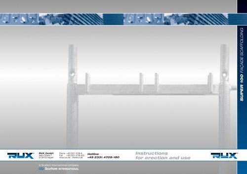
Rapid-Erection Scaffolding <strong>RUX</strong>-<strong>SUPER</strong> 1001 GeneralRapid-Erection Scaffolding <strong>RUX</strong>-<strong>SUPER</strong> 1001 GeneralThe topmost lift, in <strong>the</strong> st<strong>and</strong>ard design, is to be at a maximum <strong>of</strong> 24 m plus jack extension length above <strong>the</strong> ground.The scaffolding system is intended <strong>for</strong> <strong>use</strong> as a working scaffold in <strong>the</strong> Scaffold groups 4 – 6 as well as a protectivescaffold in accordance with DIN 4420.In general, <strong>the</strong> working loads specified in Table 1 are permissible. When widening brackets are <strong>use</strong>d on <strong>the</strong> outer side <strong>of</strong><strong>the</strong> scaffold, <strong>the</strong> scaffolding is, however, to be subjected to a maximum load <strong>of</strong> 300 kg/m2 ( Scaffold group 4, DIN 4420).Table 1: Approved scaffold groups <strong>and</strong> working loadsBay length Permissible scaffold groups Permissible working loads2.0 m 4 300 kg/m 25 450 kg/m 26 600 kg/m 22.5 m 4 300 kg/m 25 450 kg/m 23.0 m 4 300 kg/m 2Erection <strong>and</strong> dismantling <strong>of</strong> <strong>the</strong> <strong>RUX</strong>-<strong>SUPER</strong> 100 scaffolding is only to be per<strong>for</strong>med by qualified personnel.Erection, conversion <strong>and</strong> dismantling <strong>of</strong> <strong>RUX</strong>-<strong>SUPER</strong> 100 rapid-<strong>erection</strong> scaffolds may only be carried out under <strong>the</strong>supervision <strong>of</strong> a sufficiently qualified person <strong>and</strong> by qualified staff specially trained <strong>for</strong> such work <strong>and</strong> familiarized with<strong>the</strong> special conditions <strong>of</strong> each individual project. During all work on scaffolds, <strong>the</strong> occupational health <strong>and</strong> safetyregulations must be observed <strong>and</strong> complied with. Prior to starting work on scaffolds, <strong>the</strong> contractor responsible mustcarry out a risk analysis. The <strong>for</strong>m enclosed with <strong>the</strong>se instructions may be <strong>use</strong>d <strong>for</strong> this purpose. It does not claim,however, to contain a complete list <strong>of</strong> all conceivable risks that can occur in scaffolding work. There<strong>for</strong>e it remains<strong>the</strong> responsibility <strong>of</strong> <strong>the</strong> contractor to recognize any additional risks present on individual building sites <strong>and</strong> take allnecessary precautions to ensure adequate safety st<strong>and</strong>ards <strong>and</strong> to protect <strong>the</strong> health <strong>of</strong> workers.These instructions describe <strong>the</strong> <strong>erection</strong> <strong>and</strong> dismantling <strong>of</strong> <strong>the</strong> st<strong>and</strong>ard version. If this scaffolding system is <strong>use</strong>d tobuild scaffolds that deviate from <strong>the</strong> st<strong>and</strong>ard version, <strong>the</strong> deviations must be measurable according to <strong>the</strong> technicalconstruction regulations <strong>and</strong> <strong>the</strong> provisions <strong>of</strong> <strong>the</strong> National Technical Approval No. Z-8.1-185.2, <strong>and</strong> <strong>the</strong>y must beverified in each individual case. The verification can be waived if <strong>the</strong> scaffold is built according to a generallyrecognized st<strong>and</strong>ard structure. The scaffold may only be erected, dismantled, converted <strong>and</strong> <strong>use</strong>d as described in <strong>the</strong>seinstructions <strong>and</strong> exclusively with components included in <strong>the</strong> parts list contained in <strong>the</strong>se instructions. O<strong>the</strong>r structuresare possible, but subject to specific verification.After <strong>erection</strong> <strong>and</strong> prior to <strong>use</strong>, each scaffold must be inspected by sufficiently qualified persons. The inspection mustbe documented. During <strong>erection</strong>, dismantling <strong>and</strong> conversion, <strong>the</strong> scaffold must be marked with a “no admittance”prohibition sign <strong>and</strong> cordoned <strong>of</strong>f effectively to prevent unauthorized access to <strong>the</strong> danger zone (Appendix 2,Section 5.2.5 safety regulations).Scaffolding contractors must inspect each scaffold upon completion, scaffolds <strong>and</strong> parts <strong>of</strong> scaffolds not yet completedmust be barred, marked with a “no admittance” sign <strong>and</strong> cordoned <strong>of</strong>f effectively.The decking <strong>of</strong> <strong>RUX</strong>-<strong>SUPER</strong> 100 rapid-<strong>erection</strong> scaffolds has been verified <strong>and</strong> approved according to table 2 <strong>for</strong>working loads on scaffold groups according to DIN 4420, part 1: 1990-12, table 2 <strong>and</strong> <strong>for</strong> <strong>use</strong> on safety scaffolding <strong>and</strong>ro<strong>of</strong> safety barriers to withst<strong>and</strong> <strong>the</strong> impact <strong>of</strong> falling from heights <strong>of</strong> up to 2.00 m.Table 2: Assignment <strong>of</strong> <strong>the</strong> planks to <strong>the</strong> Scaffold groups <strong>and</strong> <strong>the</strong>ir application in safety <strong>and</strong> ro<strong>of</strong> safety scaffolds.Description Appendix *) Use on Grid width l Use insafety scaffolds <strong>and</strong> [m] scaffold groupro<strong>of</strong> safety barriersTimber plank 2.0 59 permissible2.5 4Pr<strong>of</strong>iled timber plank2.5 510 permissible3.0 4Aluminium plank 2.5 612 permissible3.0 5Aluminium batten 2.5 513 permissible3.0 4Steel plank 2.0 614 permissible 2.5 53.0 4Aluminium ladder frame 2.5 4with integrated ladder <strong>and</strong> 45 permissibleveneer plywood (BFU 100G)3.0 32.5 4All-aluminium ladder frame46 permissiblewith integrated ladder3.0 3Solid timber decking plankd = 45 mm61 permissible 2.0 4Solid timber decking plank 2.0 562 permissibled = 48 mm 2.5 4Alu-Belagbohle 2.0 663 permissibled = 45 mm 2.5 4Aluminium ladder frame permissible 2.5 4aluminium, complete with ladder 73(decking: extruded pr<strong>of</strong>iles)permissible 3.0 3Aluminium ladder framealuminium, complete with ladder 74 permissible 2.0 5(decking: extruded pr<strong>of</strong>iles)*) appendices to National Technical Approval No. Z-8.1-185.2These instructions <strong>for</strong> <strong>erection</strong> <strong>and</strong> <strong>use</strong> are only valid <strong>for</strong> <strong>the</strong> original Rapid-Erection Scaffolding <strong>RUX</strong>-<strong>SUPER</strong> 100 from <strong>RUX</strong> <strong>GmbH</strong>, Hagen!These instructions <strong>for</strong> <strong>erection</strong> <strong>and</strong> <strong>use</strong> are only valid <strong>for</strong> <strong>the</strong> original Rapid-Erection Scaffolding <strong>RUX</strong>-<strong>SUPER</strong> 100 from <strong>RUX</strong> <strong>GmbH</strong>, Hagen!6<strong>RUX</strong> <strong>GmbH</strong> · Phone +49 2331 4709-0 · Fax +49 2331 4709-202 · Mail rux@rux.de<strong>RUX</strong> <strong>GmbH</strong> · Phone +49 2331 4709-0 · Fax +49 2331 4709-202 · Mail rux@rux.de7
Rapid-Erection Scaffolding <strong>RUX</strong>-<strong>SUPER</strong> 1002 Erection <strong>of</strong> <strong>the</strong> <strong>RUX</strong>-<strong>SUPER</strong> 100 scaffoldingRapid-Erection Scaffolding <strong>RUX</strong>-<strong>SUPER</strong> 1002 Erection <strong>of</strong> <strong>the</strong> <strong>RUX</strong>-<strong>SUPER</strong> 100 scaffolding2.1 General requirementsThe <strong>RUX</strong>-<strong>SUPER</strong> 100 components are to be visually checked <strong>for</strong> damage prior to <strong>erection</strong>. Damaged componentsmust not be <strong>use</strong>d. Only original parts bearing <strong>the</strong> labels <strong>of</strong> <strong>RUX</strong> <strong>GmbH</strong>, <strong>RUX</strong> SALES & SERVICES <strong>GmbH</strong> <strong>and</strong>Günter <strong>Rux</strong> <strong>GmbH</strong> may be <strong>use</strong>d.2.2.2 Base plates, base transoms <strong>and</strong> longitudinal tubes (ledgers)The base jacks are to be placed, full-face, on <strong>the</strong> horizontal, firm ground ( refer to Ill. 1b). Inclines are to be compensatedby wedge-shaped sole boards. The local load input is to be verified on inclines <strong>of</strong> more than 5°.The <strong>RUX</strong>-<strong>SUPER</strong> 100 scaffolding is to be erected in <strong>the</strong> sequence <strong>of</strong> <strong>the</strong> following chapters.2.2 Erection <strong>of</strong> <strong>the</strong> first bay2.2.1 Load-spreading foundationsWhen <strong>the</strong> ground is sufficiently firm to bear <strong>the</strong> loads, <strong>the</strong> scaffold can be erected without adopting any additionalmeasures..Vertical frameBase transomIf <strong>the</strong> ground is not <strong>of</strong> sufficient load-bearing nature, load-spreading supports such as planks, square timberblocks or steel beams must be placed underneath( refer to illustrations 1a <strong>and</strong> 1b).Base jackVertical frameHSPWedge-shaped sole boardSole boardSole boardHSPBase plateGround <strong>of</strong> load-bearing capacity (as per DIN 4420/1) 5° without verification <strong>of</strong> <strong>the</strong> local load diversionBase transomFull-facesupportBase jackFirm, load-bearing surfaceIllustration 1a Load-spreading foundations with sole boards.Illustration 1b Examples <strong>of</strong> foundations (in accordance with DIN 4420/1).The permissible extended length <strong>of</strong> <strong>the</strong> base jacks depends on <strong>the</strong> mode <strong>of</strong> <strong>erection</strong> selected. These arespecified in <strong>the</strong> <strong>erection</strong> sketches Chapter 2.5 (spindle extension length H Sp = distance from bottom edge <strong>of</strong>vertical frame to bottom edge <strong>of</strong> <strong>the</strong> jack base plate (refer to Ill. 1a, 1b)).These instructions <strong>for</strong> <strong>erection</strong> <strong>and</strong> <strong>use</strong> are only valid <strong>for</strong> <strong>the</strong> original Rapid-Erection Scaffolding <strong>RUX</strong>-<strong>SUPER</strong> 100 from <strong>RUX</strong> <strong>GmbH</strong>, Hagen!These instructions <strong>for</strong> <strong>erection</strong> <strong>and</strong> <strong>use</strong> are only valid <strong>for</strong> <strong>the</strong> original Rapid-Erection Scaffolding <strong>RUX</strong>-<strong>SUPER</strong> 100 from <strong>RUX</strong> <strong>GmbH</strong>, Hagen!8<strong>RUX</strong> <strong>GmbH</strong> · Phone +49 2331 4709-0 · Fax +49 2331 4709-202 · Mail rux@rux.de<strong>RUX</strong> <strong>GmbH</strong> · Phone +49 2331 4709-0 · Fax +49 2331 4709-202 · Mail rux@rux.de9
Rapid-Erection Scaffolding <strong>RUX</strong>-<strong>SUPER</strong> 100 Rapid-Erection Scaffolding <strong>RUX</strong>-<strong>SUPER</strong> 1002 Erection <strong>of</strong> <strong>the</strong> <strong>RUX</strong>-<strong>SUPER</strong> 100 scaffolding2 Erection <strong>of</strong> <strong>the</strong> <strong>RUX</strong>-<strong>SUPER</strong> 100 scaffoldingThe jacks are classified in Jack Group A approved by <strong>the</strong> construction authority under approval No. Z-8.1-185.1(Z-8.1-185.2) in accordance with Chapter 6 <strong>of</strong> DIN 4425.Base transoms are to be fitted <strong>for</strong> connecting <strong>the</strong> longitudinal tubes <strong>and</strong> are placed toge<strong>the</strong>r with <strong>the</strong>ir tubesupports over <strong>the</strong> jacks.A longitudinal tube (ledger) is hooked onto <strong>the</strong> gravity finger <strong>of</strong> <strong>the</strong> base transoms on <strong>the</strong> outer side. Thisensures that exact bay length is maintained (refer to Ill. 2)2.2.3 Adapter framesIf <strong>the</strong>re are large variations in <strong>the</strong> height <strong>of</strong> <strong>the</strong> terrain on which <strong>the</strong> scaffold is located such that <strong>the</strong>y cannot becompensated by <strong>the</strong> spindles, <strong>the</strong>n adapter frames with a height <strong>of</strong> 0.5 m, or 1.0 m, are to be fitted (Ill. 3).Vertical frameVertical diagonal braceBase jackBase jackBase transomBase jackBase transomSole boardLongitudinal tube (guardrail)Longitudinal tube (ledger)Adapter frameSole boardIllustration 3 Erection using vertical adapter frames.Illustration 2 Alignment <strong>of</strong> <strong>the</strong> bottom scaffold level using base transoms <strong>and</strong> longitudinal tubes (guardrails).If vertical diagonal braces are planned <strong>for</strong> a bay, <strong>the</strong>n diagonal braces must also be fitted between <strong>the</strong> adapterframes. Tubes <strong>of</strong> 48.3 dia. x 3.2 are to be <strong>use</strong>d <strong>and</strong> connected by swivel couplers to <strong>the</strong> st<strong>and</strong>ards.These instructions <strong>for</strong> <strong>erection</strong> <strong>and</strong> <strong>use</strong> are only valid <strong>for</strong> <strong>the</strong> original Rapid-Erection Scaffolding <strong>RUX</strong>-<strong>SUPER</strong> 100 from <strong>RUX</strong> <strong>GmbH</strong>, Hagen!These instructions <strong>for</strong> <strong>erection</strong> <strong>and</strong> <strong>use</strong> are only valid <strong>for</strong> <strong>the</strong> original Rapid-Erection Scaffolding <strong>RUX</strong>-<strong>SUPER</strong> 100 from <strong>RUX</strong> <strong>GmbH</strong>, Hagen!10 <strong>RUX</strong> <strong>GmbH</strong> · Phone +49 2331 4709-0 · Fax +49 2331 4709-202 · Mail rux@rux.de<strong>RUX</strong> <strong>GmbH</strong> · Phone +49 2331 4709-0 · Fax +49 2331 4709-202 · Mail rux@rux.de 11
Rapid-Erection Scaffolding <strong>RUX</strong>-<strong>SUPER</strong> 100 Rapid-Erection Scaffolding <strong>RUX</strong>-<strong>SUPER</strong> 1002 Erection <strong>of</strong> <strong>the</strong> <strong>RUX</strong>-<strong>SUPER</strong> 100 scaffolding2 Erection <strong>of</strong> <strong>the</strong> <strong>RUX</strong>-<strong>SUPER</strong> 100 scaffolding2.2.4 Vertical framesThe vertical frames are to be placed perpendicular on <strong>the</strong> base plates, or jacks, at <strong>the</strong> intended distance from<strong>the</strong> wall. In doing so, care should be taken to ensure that <strong>the</strong> clear space between plank <strong>and</strong> facade must be amaximum <strong>of</strong> 0.30 m.2.2.5 Fitting <strong>the</strong> planksApproved planks are to be fitted over <strong>the</strong> full width <strong>of</strong> <strong>the</strong> scaffold. They are located by means <strong>of</strong> tubular spigotswelded to <strong>the</strong> cross bearers (Ill. 5).The vertical frame is to be secured against falling over by fitting a vertical diagonal brace. This brace is hookedonto <strong>the</strong> outer gravity locks, whereby care should be taken to ensure that <strong>the</strong> outer hole is <strong>use</strong>d on <strong>the</strong> side where<strong>the</strong> twin-holes are located (Ill. 4).System plankVertical frameVertical diagonal braceVertical frameBase transomBase jackLongitudinal tube(ledger)Vertical diagonal braceSole boardBase jackIllustration 5 Erection <strong>of</strong> <strong>the</strong> first bay (base bay).Sole boardBase transomLongitudinal tube (ledger)Illustration 4 Fitting <strong>the</strong> vertical frame <strong>and</strong> achieving stability by means <strong>of</strong> vertical diagonal braces.2.2.6 BracesThe longitudinal braces are to be fitted to <strong>the</strong> outer side <strong>of</strong> <strong>the</strong> scaffold.The vertical diagonal braces <strong>and</strong> longitudinal tubes serve to create stability <strong>and</strong> onward transmission <strong>of</strong> <strong>the</strong><strong>for</strong>ces into <strong>the</strong> ground underneath <strong>the</strong> outer scaffold face that runs parallel to <strong>the</strong> facade.2.2.7 AlignmentThe first bay must be aligned both perpendicular <strong>and</strong> horizontally. The distance from <strong>the</strong> wall should be checkedi.e. <strong>the</strong> maximum distance between <strong>the</strong> planks <strong>and</strong> <strong>the</strong> facade must not exceed 30 cm if a guardrail is not fitted.These instructions <strong>for</strong> <strong>erection</strong> <strong>and</strong> <strong>use</strong> are only valid <strong>for</strong> <strong>the</strong> original Rapid-Erection Scaffolding <strong>RUX</strong>-<strong>SUPER</strong> 100 from <strong>RUX</strong> <strong>GmbH</strong>, Hagen!These instructions <strong>for</strong> <strong>erection</strong> <strong>and</strong> <strong>use</strong> are only valid <strong>for</strong> <strong>the</strong> original Rapid-Erection Scaffolding <strong>RUX</strong>-<strong>SUPER</strong> 100 from <strong>RUX</strong> <strong>GmbH</strong>, Hagen!12 <strong>RUX</strong> <strong>GmbH</strong> · Phone +49 2331 4709-0 · Fax +49 2331 4709-202 · Mail rux@rux.de<strong>RUX</strong> <strong>GmbH</strong> · Phone +49 2331 4709-0 · Fax +49 2331 4709-202 · Mail rux@rux.de 13
Rapid-Erection Scaffolding <strong>RUX</strong>-<strong>SUPER</strong> 100 Rapid-Erection Scaffolding <strong>RUX</strong>-<strong>SUPER</strong> 1002.3 Erection <strong>of</strong> <strong>the</strong> subsequent bays2.3 Erection <strong>of</strong> <strong>the</strong> subsequent bays2.3 Erection <strong>of</strong> <strong>the</strong> subsequent bays2.3.1 St<strong>and</strong>ard baysWhen <strong>the</strong> base bay has been completed with braces <strong>and</strong> aligned, <strong>the</strong> next bays can be assembled. The sameprocedures are to be adopted as described in Chapter 2.2.By fitting <strong>the</strong> vertical diagonal braces, <strong>the</strong> <strong>RUX</strong>-<strong>SUPER</strong> 100 rapid-<strong>erection</strong> scaffold plumbs itself automatically in<strong>the</strong> perpendicular.2.3.2 Additional bracesOn some modes <strong>of</strong> <strong>erection</strong>, longitudinal tubes (ledgers) are also to be fitted on <strong>the</strong> inside (refer to details onvarious modes <strong>of</strong> <strong>erection</strong> in Chapter 2.5). Tubes <strong>of</strong> 48.3 dia. x 3.2 are to be <strong>use</strong>d <strong>for</strong> this purpose <strong>and</strong> connectedto <strong>the</strong> st<strong>and</strong>ards by means <strong>of</strong> st<strong>and</strong>ard couplers.In a number <strong>of</strong> cases, cross diagonal braces are to be fitted in <strong>the</strong> bottom vertical frames (refer to details on <strong>the</strong>various modes <strong>of</strong> <strong>erection</strong> in Chapter 2.5). Here again, tubes <strong>of</strong> 48.3 dia. x 3.2 should be <strong>use</strong>d with connectionto <strong>the</strong> st<strong>and</strong>ards being effected by means <strong>of</strong> swivel couplers (Ill. 7).The vertical diagonal braces <strong>and</strong> longitudinal tubes (ledgers) are supplemented in accordance with <strong>the</strong> variousmodes <strong>of</strong> <strong>erection</strong> described (refer to Chapter 2.5). One vertical diagonal brace is to be fitted to a maximum <strong>of</strong>five bays (Ill. 6).Base baySwivel couplerSystem plankCross diagonal braceVertical frameVertical diagonal braceSt<strong>and</strong>ardcouplerBase jackBase transomLongitudinal tube(ledger)Base baySole boardIllustration 7 Bay with additional braces.Illustration 6 Erection <strong>of</strong> <strong>the</strong> bottom scaffold level (<strong>for</strong> additional braces refer to Chapter 2.5 various modes <strong>of</strong> <strong>erection</strong>).These instructions <strong>for</strong> <strong>erection</strong> <strong>and</strong> <strong>use</strong> are only valid <strong>for</strong> <strong>the</strong> original Rapid-Erection Scaffolding <strong>RUX</strong>-<strong>SUPER</strong> 100 from <strong>RUX</strong> <strong>GmbH</strong>, Hagen!These instructions <strong>for</strong> <strong>erection</strong> <strong>and</strong> <strong>use</strong> are only valid <strong>for</strong> <strong>the</strong> original Rapid-Erection Scaffolding <strong>RUX</strong>-<strong>SUPER</strong> 100 from <strong>RUX</strong> <strong>GmbH</strong>, Hagen!14 <strong>RUX</strong> <strong>GmbH</strong> · Phone +49 2331 4709-0 · Fax +49 2331 4709-202 · Mail rux@rux.de<strong>RUX</strong> <strong>GmbH</strong> · Phone +49 2331 4709-0 · Fax +49 2331 4709-202 · Mail rux@rux.de 15
Rapid-Erection Scaffolding <strong>RUX</strong>-<strong>SUPER</strong> 1002.3 Erection <strong>of</strong> <strong>the</strong> subsequent baysRapid-Erection Scaffolding <strong>RUX</strong>-<strong>SUPER</strong> 1002.3 Erection <strong>of</strong> <strong>the</strong> subsequent bays2.3.3 Building cornersConstruction <strong>of</strong> <strong>the</strong> scaffold at <strong>the</strong> corner <strong>of</strong> a structure is depicted, in principle, in <strong>the</strong> illustrations 8a <strong>and</strong> 8b.The st<strong>and</strong>ards <strong>of</strong> <strong>the</strong> vertical frames located immediately alongside one ano<strong>the</strong>r are connected vertically ata distance <strong>of</strong> 4 m by a scaffold tube <strong>and</strong> two st<strong>and</strong>ard couplers. The gap created between <strong>the</strong> vertical facadecomponents that meet up with one ano<strong>the</strong>r must be covered in <strong>the</strong> event that it is larger than 8 cm.Fur<strong>the</strong>r details on <strong>the</strong> construction <strong>of</strong> corners with additional ties are contained in Chapter 2.4.6.Tie bar – tie same as perimeterst<strong>and</strong>ards (e. g. maximum verticaldistance H = 4.00 m)Tie baraccording to <strong>the</strong> <strong>erection</strong> variants asdescribed in chapter 2.5 (additional“V” tie: refer to Chapter 2.4.6)Tie barTie bar with st<strong>and</strong>ard coupler(maximum vertical space H = 4,00 m)Covering required<strong>for</strong> gaps larger than 8 cmIllustration 8a Corner construction through connecting <strong>the</strong> frame st<strong>and</strong>ards by means <strong>of</strong> tubes <strong>and</strong> st<strong>and</strong>ard couplers.Tie bar – tie same as perimeterst<strong>and</strong>ards (e. g. maximum verticaldistance H = 4.00 m)Tie baraccording to <strong>the</strong> <strong>erection</strong> variants asdescribed in chapter 2.5 (additional“V” tie: refer to Chapter 2.4.6)Scaffold tube withst<strong>and</strong>ard coupler(maximum verticaldistance H = 4.00 m)Covering not required<strong>for</strong> gaps smaller than 8 cmIllustration 8b Construction <strong>of</strong> corner scaffolds with no covering <strong>of</strong> <strong>the</strong> gap.These instructions <strong>for</strong> <strong>erection</strong> <strong>and</strong> <strong>use</strong> are only valid <strong>for</strong> <strong>the</strong> original Rapid-Erection Scaffolding <strong>RUX</strong>-<strong>SUPER</strong> 100 from <strong>RUX</strong> <strong>GmbH</strong>, Hagen!These instructions <strong>for</strong> <strong>erection</strong> <strong>and</strong> <strong>use</strong> are only valid <strong>for</strong> <strong>the</strong> original Rapid-Erection Scaffolding <strong>RUX</strong>-<strong>SUPER</strong> 100 from <strong>RUX</strong> <strong>GmbH</strong>, Hagen!16<strong>RUX</strong> <strong>GmbH</strong> · Fon +49 2331 4709-0 · Fax +49 2331 4709-202 · Mail rux@rux.de<strong>RUX</strong> <strong>GmbH</strong> · Phone +49 2331 4709-0 · Fax +49 2331 4709-202 · Mail rux@rux.de17
Rapid-Erection Scaffolding <strong>RUX</strong>-<strong>SUPER</strong> 1002.3 Erection <strong>of</strong> <strong>the</strong> subsequent baysRapid-Erection Scaffolding <strong>RUX</strong>-<strong>SUPER</strong> 1002.3 Erection <strong>of</strong> <strong>the</strong> subsequent bays2.3.4 Scaffold access laddersThe access ladders are to be fitted be<strong>for</strong>e work starts on <strong>the</strong> first lift.Inner access ladders (see illustration 9):In <strong>the</strong> case <strong>of</strong> <strong>the</strong> inner access ladders, <strong>the</strong> 0.59 m wide aluminium ladder frames are fitted to <strong>the</strong> scaffold <strong>and</strong>a 0.29 m wide plank placed alongside in each case.The aluminium ladder frames are to be fitted such that <strong>the</strong> ladders are located alternately on <strong>the</strong> right <strong>and</strong>left-h<strong>and</strong> sides.Planks are to be fitted on additional plank bearers immediately above <strong>the</strong> jacks <strong>and</strong> which are slotted over <strong>the</strong>base jacks prior to <strong>the</strong> vertical frames being erected (Ill. 9;10).Access ladders located in front <strong>of</strong> <strong>the</strong> main scaffold (refer to illustration 10):A separate 0.65 m wide bay is erected in front <strong>of</strong> <strong>the</strong> actual working scaffold to which aluminium ladder framesare fitted.The access ladders fitted in this manner may only be loaded to a maximum <strong>of</strong> 200 kg/m 2 on one lift (inaccordance with Scaffold group 3, DIN 4420).This construction is described in detail in Chapter 2.5.3.5.This procedure may be adopted <strong>for</strong> <strong>the</strong> following modes <strong>of</strong> <strong>erection</strong>:• Scaffold group 5 (max. 450 kg/m 2 on one lift – I = 2.00 m• Scaffold group 4 (max. 300 kg/m 2 on one lift – I = 2.50 mThe structural design is described in detail in Chapter 2.5.3.4.TieTieIllustration 10 Access ladders in front <strong>of</strong> working scaffold.Vertical column <strong>of</strong> framesIllustration 9 Bay with inner access ladders (2.0 m bay length only – Scaffold group 5).These instructions <strong>for</strong> <strong>erection</strong> <strong>and</strong> <strong>use</strong> are only valid <strong>for</strong> <strong>the</strong> original Rapid-Erection Scaffolding <strong>RUX</strong>-<strong>SUPER</strong> 100 from <strong>RUX</strong> <strong>GmbH</strong>, Hagen!These instructions <strong>for</strong> <strong>erection</strong> <strong>and</strong> <strong>use</strong> are only valid <strong>for</strong> <strong>the</strong> original Rapid-Erection Scaffolding <strong>RUX</strong>-<strong>SUPER</strong> 100 from <strong>RUX</strong> <strong>GmbH</strong>, Hagen!18<strong>RUX</strong> <strong>GmbH</strong> · Phone +49 2331 4709-0 · Fax +49 2331 4709-202 · Mail rux@rux.de<strong>RUX</strong> <strong>GmbH</strong> · Phone +49 2331 4709-0 · Fax +49 2331 4709-202 · Mail rux@rux.de19
Rapid-Erection Scaffolding <strong>RUX</strong>-<strong>SUPER</strong> 100 Rapid-Erection Scaffolding <strong>RUX</strong>-<strong>SUPER</strong> 1002.4 Erection <strong>of</strong> <strong>the</strong> subsequent lifts2.4 Erection <strong>of</strong> <strong>the</strong> subsequent lifts2.4 Erection <strong>of</strong> <strong>the</strong> subsequent liftsThe measures suggested in <strong>the</strong> next chapter to increase safety during assembly, dismantling <strong>and</strong>conversion <strong>of</strong> scaffolds are to be understood as helpful suggestions <strong>for</strong> scaffolding contractors only, notas m<strong>and</strong>atory specifications.The precautionary steps suggested <strong>the</strong>re have been devised by a committee consisting <strong>of</strong> scaffoldingcontractors, leading German scaffold manufacturers <strong>and</strong> <strong>the</strong> German Federal Association <strong>of</strong> ScaffoldingContractors on <strong>the</strong> basis <strong>of</strong> a joint risk analysis. Although current accident statistics in <strong>the</strong> <strong>erection</strong>,dismantling <strong>and</strong> conversion <strong>of</strong> scaffolds do not call <strong>for</strong> m<strong>and</strong>atory changes in current scaffoldingpractices, <strong>the</strong> objective <strong>of</strong> <strong>the</strong> committee’s work was to improve scaffolding safety st<strong>and</strong>ards in areaswhere, in <strong>the</strong>ory, a danger <strong>of</strong> falls could exist.Erection, dismantling <strong>and</strong> conversion <strong>of</strong> scaffolds always involves a risk <strong>of</strong> falls.Work on scaffolds must be carried out in such a way as to minimise <strong>the</strong> risk <strong>of</strong> falls. Prior to commencement<strong>of</strong> work, scaffolding contractors (or principals) must have a risk analysis carried out <strong>for</strong> eachindividual project <strong>and</strong> take appropriate precautions to minimise <strong>the</strong> danger <strong>of</strong> falls.It is <strong>the</strong> task <strong>of</strong> supervisors responsible <strong>for</strong> <strong>the</strong> <strong>erection</strong> <strong>and</strong> dismantling <strong>of</strong> scaffolds to take appropriatemeasures to prevent falls <strong>and</strong> <strong>the</strong>ir consequences <strong>for</strong> <strong>the</strong> life <strong>and</strong> health <strong>of</strong> workers, in order to ensuremaximum safety, taking into consideration all aspects <strong>of</strong> practical feasibility, expediency <strong>and</strong> <strong>the</strong> actualrisks involved. Where possible, collective protective measures must always take priority over individualmeasures.Erection <strong>and</strong> dismantling <strong>of</strong> <strong>the</strong> basic st<strong>and</strong>ard scaffolding system with <strong>the</strong> help <strong>of</strong>an assembly guard-rail systemFor scaffolds without external brackets or bridges which con<strong>for</strong>m to <strong>the</strong> basic st<strong>and</strong>ardsystem, <strong>Rux</strong> recommends using <strong>the</strong> <strong>Rux</strong> assembly guard-rail system in <strong>the</strong> ascent bayduring <strong>erection</strong> <strong>and</strong> dismantling <strong>of</strong> <strong>the</strong> scaffold. O<strong>the</strong>r measures may be taken as an alternativeif <strong>the</strong>y provide a comparable degree <strong>of</strong> safety.The <strong>Rux</strong> assembly guard-rail system has been developed <strong>for</strong> scaffold frame structures toprovide improved protection against falls <strong>for</strong> workers taking part in <strong>the</strong> assembly <strong>and</strong> dismantling<strong>of</strong> such structures.The system consists <strong>of</strong> <strong>the</strong> following parts:Assembly guard-rail posts,assembly rails that can be mounted as h<strong>and</strong> rails <strong>and</strong>/or knee rails.The structure is an “advanced guard-rail” that can be mounted following <strong>the</strong> assembly <strong>of</strong>each top horizontal level <strong>of</strong> any scaffold frame from <strong>the</strong> horizontal level immediatelybelow it.Special warning:Principles<strong>of</strong> assemblyPossible preventive measures are:– employment <strong>of</strong> qualified workers who have been familiarized with <strong>the</strong> specific risks involved ineach case,– <strong>use</strong> <strong>of</strong> appropriate personal safety equipment (PSE)– <strong>use</strong> <strong>of</strong> an assembly guard rail <strong>for</strong> <strong>the</strong> ascent– or a combination <strong>of</strong> <strong>the</strong>se measures.It must be expressly pointed out that none <strong>of</strong> <strong>the</strong>se alternatives is a collective protective measure.Please note that <strong>Rux</strong> assembly guard-rail systems are never sufficient to prevent all risks <strong>of</strong> falls occurring during<strong>the</strong> assembly or dismantling <strong>of</strong> scaffolds!It remains <strong>the</strong> task <strong>of</strong> supervisors responsible <strong>for</strong> <strong>the</strong> assembly <strong>and</strong> dismantling <strong>of</strong> scaffolds to take additionalor o<strong>the</strong>r precautions against falls <strong>and</strong> <strong>the</strong>ir consequences <strong>for</strong> <strong>the</strong> lives <strong>and</strong> health <strong>of</strong> workers involved, in orderto provide maximum safety, taking into account all aspects <strong>of</strong> practical feasibility, expediency <strong>and</strong> <strong>the</strong> actualrisks involved. Such precautions may include certain prescribed sequences <strong>of</strong> assembly <strong>and</strong> dismantling work,personal safety equipment or <strong>the</strong> employment <strong>of</strong> specially trained staff.These instructions <strong>for</strong> <strong>erection</strong> <strong>and</strong> <strong>use</strong> are only valid <strong>for</strong> <strong>the</strong> original Rapid-Erection Scaffolding <strong>RUX</strong>-<strong>SUPER</strong> 100 from <strong>RUX</strong> <strong>GmbH</strong>, Hagen!These instructions <strong>for</strong> <strong>erection</strong> <strong>and</strong> <strong>use</strong> are only valid <strong>for</strong> <strong>the</strong> original Rapid-Erection Scaffolding <strong>RUX</strong>-<strong>SUPER</strong> 100 from <strong>RUX</strong> <strong>GmbH</strong>, Hagen!20 <strong>RUX</strong> <strong>GmbH</strong> · Phone +49 2331 4709-0 · Fax +49 2331 4709-202 · Mail rux@rux.de<strong>RUX</strong> <strong>GmbH</strong> · Phone +49 2331 4709-0 · Fax +49 2331 4709-202 · Mail rux@rux.de 21
Rapid-Erection Scaffolding <strong>RUX</strong>-<strong>SUPER</strong> 1002.4 Erection <strong>of</strong> <strong>the</strong> subsequent liftsRapid-Erection Scaffolding <strong>RUX</strong>-<strong>SUPER</strong> 1002.4 Erection <strong>of</strong> <strong>the</strong> subsequent liftsFollowing <strong>erection</strong> <strong>of</strong> <strong>the</strong> first scaffold level, <strong>the</strong> guard-rail system, consisting <strong>of</strong> two posts <strong>and</strong> a h<strong>and</strong> rail, is attachedto <strong>the</strong> outside <strong>of</strong> <strong>the</strong> frame st<strong>and</strong>ards in <strong>the</strong> bay <strong>of</strong> ascent, so that <strong>the</strong> bottom hooks on <strong>the</strong> posts are locked into <strong>the</strong> railcouplers <strong>of</strong> <strong>the</strong> vertical frames at a height <strong>of</strong> 1.00 m, <strong>and</strong> <strong>the</strong> assembly guard-rail is fixed app. 1.00 m above <strong>the</strong> tophorizontal level.Attention! The assembly guard-railsystem must be mounted frombelow in <strong>the</strong> bay <strong>of</strong> ascent, be<strong>for</strong>e<strong>the</strong> assemblyman steps onto <strong>the</strong>next level <strong>of</strong> <strong>the</strong> scaffold.The assemblymen ascend through<strong>the</strong> bay secured by <strong>the</strong> assemblyguard-rail. Starting from <strong>the</strong> securedbay, <strong>the</strong> assembly <strong>of</strong> frames <strong>and</strong>rails is continued to <strong>the</strong> left <strong>and</strong>/orto <strong>the</strong> right. Following <strong>the</strong> assembly<strong>of</strong> each frame, <strong>the</strong> three-part lateralsafety barrier, consisting <strong>of</strong> h<strong>and</strong>rail, knee rail <strong>and</strong> toe board, mustimmediately be put in place in thatbay.GuardrailVerticaldiagonalbraceIll. 11a Mode <strong>of</strong> <strong>erection</strong> IGuardrailIt must be remembered that during <strong>the</strong> assembly <strong>of</strong> each outermost frame, <strong>the</strong> assemblymen are working in an unsecuredarea <strong>for</strong> a short period (prior to assembly <strong>of</strong> <strong>the</strong> lateral safety barriers), where <strong>the</strong>re is an acute danger <strong>of</strong> falling.Prior to commencement <strong>of</strong> work, assemblymen must be instructed accordingly.After completion <strong>of</strong> <strong>the</strong> next horizontal level, <strong>the</strong> assembly guard-rail posts must be removed individually, one by one,<strong>and</strong> <strong>the</strong>n attached with <strong>the</strong>ir bottom hooks to <strong>the</strong> external st<strong>and</strong>ards <strong>of</strong> <strong>the</strong> row <strong>of</strong> frames already secured at <strong>the</strong> height<strong>of</strong> <strong>the</strong> back rail.Dismantling <strong>of</strong> <strong>the</strong> assembly guard-rail is not necessary, since <strong>the</strong> rail system is telescopic, thanks to a slotted hole.For <strong>the</strong> dismantling <strong>of</strong> scaffolds, <strong>the</strong> sequence <strong>of</strong> steps in <strong>the</strong> <strong>use</strong> <strong>of</strong> this system is reversed.Ill. 11b Mode <strong>of</strong> <strong>erection</strong> IIVerticaldiagonalbraceAttachment points <strong>for</strong> personal safety equipment (PSE):In <strong>RUX</strong>-<strong>SUPER</strong> 100 rapid-<strong>erection</strong> scaffolds, PSE may only be attached to <strong>the</strong> st<strong>and</strong>ards <strong>and</strong> <strong>the</strong> top horizontal ledgers<strong>of</strong> <strong>the</strong> vertical frames.Back rails, diagonals, toe boards <strong>and</strong> rail posts are unsuitable as PSE attachment points.The <strong>use</strong> <strong>of</strong> PSE on st<strong>and</strong>ard scaffolds that have not yetbeen tied is prohibited, beca<strong>use</strong> it would involve <strong>the</strong>risk <strong>of</strong> <strong>the</strong> whole scaffolding structure being pulleddown by <strong>the</strong> fall <strong>of</strong> one person. The <strong>use</strong> <strong>of</strong> PSE isrecommended only from <strong>the</strong> 3rd level <strong>of</strong> a scaffold orfrom a minimum height <strong>of</strong> 5.00 m upwards, since aperson falling from a lesser height would already touch<strong>the</strong> ground prior to <strong>the</strong> safety mechanism taking effect,due to <strong>the</strong> length <strong>of</strong> rope involved plus his/her ownbody height.Basically, <strong>the</strong> maximum length <strong>of</strong> attachment ropepermissible <strong>for</strong> PSE is 3.00 m.If PSE hooks are attached to st<strong>and</strong>ards <strong>of</strong> scaffold frames, <strong>the</strong> hooks may come to lie on rails mounted to <strong>the</strong> scaffold.In <strong>the</strong> event <strong>of</strong> <strong>the</strong> person secured by this device falling down, such hooks may be subjected to horizontal bending, whichsome hooks found on building sites are unable to withst<strong>and</strong>. There<strong>for</strong>e <strong>the</strong> <strong>use</strong>r must ascertain from <strong>the</strong> manufacturer<strong>of</strong> his PSE whe<strong>the</strong>r <strong>the</strong> hooks have a sufficient load capacity <strong>for</strong> <strong>the</strong>ir being attached in such positions.Basically, only attachment devices according to DIN EN 362 may be <strong>use</strong>d.Prior to <strong>the</strong> <strong>use</strong> <strong>of</strong> any PSE, an individual analysis must be carried out on how, in <strong>the</strong> event <strong>of</strong> an accident, a person whohas fallen <strong>and</strong> is secured by PSE can be rescued.A person who has fallen from a scaffold will be suspended in his PSE harness ei<strong>the</strong>r in front <strong>of</strong> a horizontal level orbetween two such levels. The rescuers must pull such a person onto <strong>the</strong> scaffold level within easiest reach. This makesit necessary <strong>for</strong> <strong>the</strong> rescuers to attach <strong>the</strong>mselves with <strong>the</strong>ir own PSE <strong>and</strong> possibly to remove <strong>the</strong> lateral safety barrier<strong>of</strong> <strong>the</strong> bay involved. Only after <strong>the</strong> accident victim has been moved to a safe position <strong>and</strong> <strong>the</strong> catch-rope has beencompletely freed from <strong>the</strong> load, may <strong>the</strong> hook be detached from <strong>the</strong> attachment point (if necessary, <strong>the</strong> rope must besevered!). After having withstood one fall, <strong>the</strong> rope, attachment device <strong>and</strong> fall impact absorber must not be <strong>use</strong>d again.Assembly <strong>and</strong> dismantling without an advanced assembly guard-rail system, with PSE:For <strong>the</strong> assembly <strong>and</strong> dismantling <strong>of</strong> scaffolding structures deviating from <strong>the</strong> basic st<strong>and</strong>ard system <strong>and</strong> special scaffoldingstructures not described in <strong>the</strong>se <strong>erection</strong> instructions, <strong>the</strong> <strong>use</strong> <strong>of</strong> personal safety equipment is recommended, wherethis is expedient in view <strong>of</strong> <strong>the</strong> local conditions. Alternatively, o<strong>the</strong>r preventive measures providing at least an equaldegree <strong>of</strong> safety may be taken.Erection <strong>of</strong> scaffolds without advanced rail system <strong>and</strong> without PSE:In such cases only specially trained staff who have been familiarized with <strong>the</strong> risks involved <strong>and</strong> are not affected byheights may carry out <strong>the</strong> work. Persons working in scaffold areas with a danger <strong>of</strong> falls must be both physically <strong>and</strong>mentally able to carry out <strong>the</strong> type <strong>of</strong> work required in such areas.Users <strong>of</strong> <strong>the</strong> scaffold must keep away from areas without collective lateral safety barriers consisting <strong>of</strong> backrail, knee rail <strong>and</strong> toe board.These instructions <strong>for</strong> <strong>erection</strong> <strong>and</strong> <strong>use</strong> are only valid <strong>for</strong> <strong>the</strong> original Rapid-Erection Scaffolding <strong>RUX</strong>-<strong>SUPER</strong> 100 from <strong>RUX</strong> <strong>GmbH</strong>, Hagen!These instructions <strong>for</strong> <strong>erection</strong> <strong>and</strong> <strong>use</strong> are only valid <strong>for</strong> <strong>the</strong> original Rapid-Erection Scaffolding <strong>RUX</strong>-<strong>SUPER</strong> 100 from <strong>RUX</strong> <strong>GmbH</strong>, Hagen!22<strong>RUX</strong> <strong>GmbH</strong> · Phone +49 2331 4709-0 · Fax +49 2331 4709-202 · Mail rux@rux.de<strong>RUX</strong> <strong>GmbH</strong> · Phone +49 2331 4709-0 · Fax +49 2331 4709-202 · Mail rux@rux.de23
Rapid-Erection Scaffolding <strong>RUX</strong>-<strong>SUPER</strong> 1002.4 Erection <strong>of</strong> <strong>the</strong> subsequent liftsRapid-Erection Scaffolding <strong>RUX</strong>-<strong>SUPER</strong> 1002.4 Erection <strong>of</strong> <strong>the</strong> subsequent lifts2.4.1 Conveyance <strong>of</strong> scaffold componentsIn cases where <strong>the</strong> bay height exceeds 8 m (height <strong>of</strong> <strong>the</strong> topmost lift above ground level), lifts must be <strong>use</strong>d toassist in <strong>erection</strong> <strong>and</strong> dismantling. Manually operated cable hoists are also considered to be lifts.Lifts can be dispensed with when <strong>the</strong> bay height does not exceed 14 m <strong>and</strong> <strong>the</strong> length <strong>of</strong> <strong>the</strong> scaffolding is notmore than 10 m.On bays where components are conveyed vertically by h<strong>and</strong>, guardrails <strong>and</strong> intermediate rails must be in place.At least one worker must be present on each individual lift (deck) in <strong>the</strong> event <strong>of</strong> manual h<strong>and</strong>ling <strong>of</strong> components(refer to Ill. 11a <strong>and</strong> 11b).2.4.2 Assembly <strong>of</strong> <strong>the</strong> vertical framesMode <strong>of</strong> <strong>erection</strong> l: The vertical frames are to be fitted from <strong>the</strong> far column <strong>of</strong> frames towards <strong>the</strong> bay by conveying<strong>the</strong>m vertically. The guardrails must <strong>the</strong>n be fitted, starting in <strong>the</strong> bay in which vertical conveyance takesplace (refer to Ill. 11a).2.4.5 Guard (guardrails)Missing intermediate rails <strong>and</strong> toe boards, as well as <strong>the</strong> complete guarding at <strong>the</strong> ends <strong>of</strong> <strong>the</strong> scaffold, are to befitted at all lifts not <strong>use</strong>d <strong>for</strong> <strong>the</strong> <strong>erection</strong> <strong>of</strong> <strong>the</strong> scaffold.The guardrails <strong>and</strong> intermediate rails are attached to <strong>the</strong> inner gravity locks on <strong>the</strong> vertical frames or, in <strong>the</strong> case<strong>of</strong> vertical frames with lugs, to <strong>the</strong> lugs. Gravity locks that do not point in <strong>the</strong> direction <strong>of</strong> <strong>the</strong> planking (e.g. locks<strong>for</strong> connection <strong>of</strong> <strong>the</strong> vertical diagonal braces) may not be <strong>use</strong>d <strong>for</strong> attaching guard rails or intermediate rails.Guardrail posts are fitted above <strong>the</strong> 1st lift <strong>for</strong> mounting <strong>the</strong> guardrails. Care is also to be taken to ensure that<strong>the</strong> gravity locks <strong>for</strong> fitting <strong>the</strong> guardrails <strong>and</strong> intermediate rails point in <strong>the</strong> direction <strong>of</strong> <strong>the</strong> decking (planks).In cases where outer brackets are <strong>use</strong>d, tubes <strong>of</strong> 48.3 dia. x 32.2 with st<strong>and</strong>ard couplers are fitted above <strong>the</strong> topmostlift at <strong>the</strong> ends to provide guardrails <strong>and</strong> intermediate rails (refer to Ill. 12 <strong>and</strong> 13).The toe boards <strong>and</strong> <strong>the</strong>ir fittings are slotted in between <strong>the</strong> outer st<strong>and</strong>ards. Attention must be paid here to ensuring<strong>the</strong> correct position <strong>of</strong> <strong>the</strong> inner <strong>and</strong> outer sides (refer to <strong>the</strong> marking on <strong>the</strong> end fittings <strong>of</strong> <strong>the</strong> toe boards).Mode <strong>of</strong> <strong>erection</strong> II: The vertical frames are to be mounted starting in <strong>the</strong> bay in which vertical transportation takesplace. The guardrail must be installed immediately after <strong>the</strong> appropriate frame has been fitted (refer to Ill. 11b).2.4.3 Planks (decking)Approved planks are to be installed at each lift over <strong>the</strong> full width <strong>of</strong> <strong>the</strong> scaffold. <strong>the</strong>y are hooked onto <strong>the</strong> tubularspigots welded to <strong>the</strong> transoms (bearer rails).Normally <strong>the</strong> planks are secured against unintentional dislocation by <strong>the</strong> bottom cross bar <strong>of</strong> <strong>the</strong> vertical frames,or on <strong>the</strong> topmost lift, by <strong>the</strong> guardrail or barrier supports. In cases where outer brackets are <strong>use</strong>d, plankretainers are to be fitted above <strong>the</strong> vertical frame on <strong>the</strong> topmost lift.2.4.4 BracesThe braces (vertical diagonals) are to be fitted as <strong>erection</strong> progresses <strong>and</strong> as described in Chapter 2.2.The required number <strong>of</strong> vertical diagonal braces is illustrated in Chapter 2.5. Braces are to be installed at eachlift, at least in every 5th bay.The direction <strong>of</strong> inclination <strong>of</strong> <strong>the</strong> vertical diagonals can be selected at r<strong>and</strong>om, i.e. fitting can be successive orin <strong>the</strong> <strong>for</strong>m <strong>of</strong> a tower.These instructions <strong>for</strong> <strong>erection</strong> <strong>and</strong> <strong>use</strong> are only valid <strong>for</strong> <strong>the</strong> original Rapid-Erection Scaffolding <strong>RUX</strong>-<strong>SUPER</strong> 100 from <strong>RUX</strong> <strong>GmbH</strong>, Hagen!These instructions <strong>for</strong> <strong>erection</strong> <strong>and</strong> <strong>use</strong> are only valid <strong>for</strong> <strong>the</strong> original Rapid-Erection Scaffolding <strong>RUX</strong>-<strong>SUPER</strong> 100 from <strong>RUX</strong> <strong>GmbH</strong>, Hagen!24<strong>RUX</strong> <strong>GmbH</strong> · Phone +49 2331 4709-0 · Fax +49 2331 4709-202 · Mail rux@rux.de<strong>RUX</strong> <strong>GmbH</strong> · Phone +49 2331 4709-0 · Fax +49 2331 4709-202 · Mail rux@rux.de25
Rapid-Erection Scaffolding <strong>RUX</strong>-<strong>SUPER</strong> 1002.4 Erection <strong>of</strong> <strong>the</strong> subsequent liftsRapid-Erection Scaffolding <strong>RUX</strong>-<strong>SUPER</strong> 1002.4 Erection <strong>of</strong> <strong>the</strong> subsequent liftsWire mesh barrierPostGuardrail postScaffold tubeSt<strong>and</strong>ard couplerGuardrailScaffold tubeGuardrail postSt<strong>and</strong>ard couplerPlank retainerGap coverToe boardPlank retainerGap coverToe boardWidening bracketwith plank retainerScrew M12Widening bracket,2-plankVertical frameWidening bracketwith plank retainerScrew M12Widening bracket,2-plankVertical framePropPropDouble end guardrailDouble end guardrailIllustration 12Illustration 13These instructions <strong>for</strong> <strong>erection</strong> <strong>and</strong> <strong>use</strong> are only valid <strong>for</strong> <strong>the</strong> original Rapid-Erection Scaffolding <strong>RUX</strong>-<strong>SUPER</strong> 100 from <strong>RUX</strong> <strong>GmbH</strong>, Hagen!These instructions <strong>for</strong> <strong>erection</strong> <strong>and</strong> <strong>use</strong> are only valid <strong>for</strong> <strong>the</strong> original Rapid-Erection Scaffolding <strong>RUX</strong>-<strong>SUPER</strong> 100 from <strong>RUX</strong> <strong>GmbH</strong>, Hagen!26<strong>RUX</strong> <strong>GmbH</strong> · Phone +49 2331 4709-0 · Fax +49 2331 4709-202 · Mail rux@rux.de<strong>RUX</strong> <strong>GmbH</strong> · Phone +49 2331 4709-0 · Fax +49 2331 4709-202 · Mail rux@rux.de27
Rapid-Erection Scaffolding <strong>RUX</strong>-<strong>SUPER</strong> 1002.4 Erection <strong>of</strong> <strong>the</strong> subsequent liftsRapid-Erection Scaffolding <strong>RUX</strong>-<strong>SUPER</strong> 1002.4 Erection <strong>of</strong> <strong>the</strong> subsequent lifts2.4.6 Ties (tie spacing <strong>and</strong> tie <strong>for</strong>ces)The tie spacing <strong>for</strong> <strong>the</strong> various modes <strong>of</strong> <strong>erection</strong> can be taken from <strong>the</strong> sketches in Chapter 2.5. The tie <strong>for</strong>cesare also to be found in <strong>the</strong> appropriate tables in <strong>the</strong> same chapter.Ties are to be installed as <strong>erection</strong> <strong>of</strong> <strong>the</strong> scaffold progresses. Use bolts <strong>of</strong> at least 12 mm dia., or equivalentmeans, to fasten <strong>the</strong> ties to <strong>the</strong> facade.In <strong>the</strong> event that ties must be replaced prematurely, equivalent substitutes must be provided be<strong>for</strong>eh<strong>and</strong>.2.4.7 Scaffold tie barsAll tie bars are to be fixed in <strong>the</strong> vicinity <strong>of</strong> <strong>the</strong> nodes to <strong>the</strong> inner st<strong>and</strong>ards using normal couplers.2.4.7.1 Short tie barsThe short tie bars are to be arranged at a right angle to <strong>the</strong> facade <strong>and</strong> connected by means <strong>of</strong> a st<strong>and</strong>ardcoupler to <strong>the</strong> inner st<strong>and</strong>ard (refer to Ill. 15).Additional ties <strong>for</strong> access ladders:The perimeter st<strong>and</strong>ards <strong>of</strong> <strong>the</strong> access ladders are to be tied to <strong>the</strong> facade at each tying level. The verticalspacing <strong>of</strong> <strong>the</strong> ties must not exceed 4.0 m.Ties in corner areas:An additional “V” tie (refer to Ill. 8 a) is required in <strong>the</strong> case <strong>of</strong> uncovered scaffolds at each tie level <strong>for</strong> dispersion<strong>of</strong> <strong>the</strong> wind loads in <strong>the</strong> vicinity <strong>of</strong> <strong>the</strong> corners.Vertical frameTie bar tie same as perimeter st<strong>and</strong>ards(e. g. maximum vertical distance H = 4.00 m)Additional “V” tie at each tie level(on uncovered scaffolds only)Tie barSCSystem planksSingle-plankbracketTie barSCCovering required<strong>for</strong> gaps larger than 8 cmCovering required on gap <strong>of</strong> more than 8 cm, e. g. in accordance with appendix 50Illustration 15 Short tie bars.Illustration 14 Additional ties at corners on uncovered scaffolds.These instructions <strong>for</strong> <strong>erection</strong> <strong>and</strong> <strong>use</strong> are only valid <strong>for</strong> <strong>the</strong> original Rapid-Erection Scaffolding <strong>RUX</strong>-<strong>SUPER</strong> 100 from <strong>RUX</strong> <strong>GmbH</strong>, Hagen!These instructions <strong>for</strong> <strong>erection</strong> <strong>and</strong> <strong>use</strong> are only valid <strong>for</strong> <strong>the</strong> original Rapid-Erection Scaffolding <strong>RUX</strong>-<strong>SUPER</strong> 100 from <strong>RUX</strong> <strong>GmbH</strong>, Hagen!28<strong>RUX</strong> <strong>GmbH</strong> · Phone +49 2331 4709-0 · Fax +49 2331 4709-202 · Mail rux@rux.de<strong>RUX</strong> <strong>GmbH</strong> · Phone +49 2331 4709-0 · Fax +49 2331 4709-202 · Mail rux@rux.de29
Rapid-Erection Scaffolding <strong>RUX</strong>-<strong>SUPER</strong> 1002.4 Erection <strong>of</strong> <strong>the</strong> subsequent liftsRapid-Erection Scaffolding <strong>RUX</strong>-<strong>SUPER</strong> 1002.4 Erection <strong>of</strong> <strong>the</strong> subsequent lifts2.4.7.2 Long tie barsThe long tie bars are attached to <strong>the</strong> inner <strong>and</strong> outer st<strong>and</strong>ards <strong>of</strong> <strong>the</strong> vertical frame by means <strong>of</strong> st<strong>and</strong>ardcouplers. They absorb <strong>the</strong> tie <strong>for</strong>ces, both at a right angle <strong>and</strong> parallel to <strong>the</strong> facade (Ill. 16).2.4.7.3 Triangular tie barsTriangular tie bars consist <strong>of</strong> two tie bars each fitted at an angle <strong>of</strong> max. 45° to <strong>the</strong> facade, in <strong>the</strong> horizontal,by means <strong>of</strong> st<strong>and</strong>ard couplers to <strong>the</strong> inner st<strong>and</strong>ards (refer to Ill. 17).Long tie bars can also be <strong>use</strong>d to stiffen bridge girders at top cord level including tying to <strong>the</strong> facade (refer toChapter 2.5.3.2 bridge girders).Vertical frameSystem planksVertical frameSCSingle-plankbracketTie barTie barSCSingle-plankbracketSCTie barSystem planksCovering required on gap <strong>of</strong> more than 8 cm, e. g. in accordance with appendix 50Illustration 17 Triangular tie bars.Illustration 16 Long tie bars.2.4.7.4 Tying <strong>the</strong> scaffoldAttention! Scaffolds not sufficiently tied are in danger <strong>of</strong> falling over or collapsing!Tying <strong>of</strong> <strong>the</strong> scaffold is to be carried out in accordance with <strong>the</strong> Safety Regulations <strong>for</strong> Work, Protection <strong>and</strong>System Scaffolds booklet ZH 1/534.1 issued by <strong>the</strong> Construction Pr<strong>of</strong>essional Association.These instructions <strong>for</strong> <strong>erection</strong> <strong>and</strong> <strong>use</strong> are only valid <strong>for</strong> <strong>the</strong> original Rapid-Erection Scaffolding <strong>RUX</strong>-<strong>SUPER</strong> 100 from <strong>RUX</strong> <strong>GmbH</strong>, Hagen!These instructions <strong>for</strong> <strong>erection</strong> <strong>and</strong> <strong>use</strong> are only valid <strong>for</strong> <strong>the</strong> original Rapid-Erection Scaffolding <strong>RUX</strong>-<strong>SUPER</strong> 100 from <strong>RUX</strong> <strong>GmbH</strong>, Hagen!30<strong>RUX</strong> <strong>GmbH</strong> · Phone +49 2331 4709-0 · Fax +49 2331 4709-202 · Mail rux@rux.de<strong>RUX</strong> <strong>GmbH</strong> · Phone +49 2331 4709-0 · Fax +49 2331 4709-202 · Mail rux@rux.de31
Rapid-Erection Scaffolding <strong>RUX</strong>-<strong>SUPER</strong> 1002.5 Various modes <strong>of</strong> <strong>erection</strong> <strong>and</strong> fitting <strong>of</strong> ancillary componentsRapid-Erection Scaffolding <strong>RUX</strong>-<strong>SUPER</strong> 1002.5 Various modes <strong>of</strong> <strong>erection</strong> <strong>and</strong> fitting <strong>of</strong> ancillary components2.5 Various modes <strong>of</strong> <strong>erection</strong> <strong>and</strong> fitting <strong>of</strong> ancillary components2.5.1 GeneralThis chapter describes <strong>the</strong> various modes <strong>of</strong> <strong>erection</strong> as well as <strong>the</strong> tying <strong>for</strong>ces <strong>and</strong> foundation load capacities.Vertical frame:Top cross barSt<strong>and</strong>ard tubesUnder <strong>the</strong> following conditions, vertical frames with bottom cross bar T 35 x 35 x 4.5 may be <strong>use</strong>d exclusively:1.) Scaffold with inner <strong>and</strong> outer brackets (console type 2) <strong>and</strong> a bay length <strong>of</strong> L = 3.0 m <strong>and</strong>2.) Scaffold in <strong>the</strong> Group 6 (600 kg/m 2 ).In all o<strong>the</strong>r cases, vertical frames with bottom cross bar T 35 x 35 x 4 (new design) <strong>and</strong> bottom cross bar40 x 20 x 1.5 (old design) may be <strong>use</strong>d – also mixed.Table 3: Distinguishing features <strong>of</strong> vertical framesBottom cross bar“Old“ design“New“ designVertical frame Top cross bar Bottom cross bar Corner prop“New“ design Square hollow pr<strong>of</strong>ile T section Rectangular hollow pr<strong>of</strong>ile(Appendices 1; 4; 48; 49) (SHP) (RHP)52 x 52 x 2.0 T 35 x 35 x 4.5 30 x 15 x 2.0“Old“ design Square hollow pr<strong>of</strong>ile Rectangular hollow pr<strong>of</strong>ile Circular hollow pr<strong>of</strong>ile(Appendices 58 to 60) (SHP) (RHP) (CHP)50 x 2.5 40 x 20 x 1.5 Ø 21.3 x 2.0Illustration 18 “Old” <strong>and</strong> “new” design vertical frames.On several modes <strong>of</strong> <strong>erection</strong>, longitudinal tubes (ledgers) are to be fitted in <strong>the</strong> diagonal bays between <strong>the</strong>outer st<strong>and</strong>ards <strong>of</strong> <strong>the</strong> bottom vertical frames <strong>and</strong> which are attached to <strong>the</strong> guard rail gravity locks. On frameswith guardrail lugs, tubes <strong>of</strong> 48.3 dia. x 3.2 are to be fitted toge<strong>the</strong>r with st<strong>and</strong>ard couplers (see pages 35; 39;41 to 43; 49; 54 <strong>and</strong> 65).Tying patterns:The tying patterns <strong>and</strong> tie point loads are dependent on <strong>the</strong> open proportion <strong>of</strong> <strong>the</strong> facade. In this case,a distinction is made between “closed facade” <strong>and</strong> “open facade”. Closed facades have no openings whereason open facades, <strong>the</strong> proportion <strong>of</strong> openings can be up to maximum <strong>of</strong> 60% over <strong>the</strong> full facade surface.The ties required are illustrated in <strong>the</strong> <strong>erection</strong> sketches <strong>and</strong> <strong>the</strong> tie <strong>for</strong>ces can be taken from <strong>the</strong> appropriatetables.Access ladders:The fitting <strong>of</strong> access ladders is described in Chapters 2.5.3.4 <strong>and</strong> 2.5.3.5 (see pages 92 – 95).These instructions <strong>for</strong> <strong>erection</strong> <strong>and</strong> <strong>use</strong> are only valid <strong>for</strong> <strong>the</strong> original Rapid-Erection Scaffolding <strong>RUX</strong>-<strong>SUPER</strong> 100 from <strong>RUX</strong> <strong>GmbH</strong>, Hagen!These instructions <strong>for</strong> <strong>erection</strong> <strong>and</strong> <strong>use</strong> are only valid <strong>for</strong> <strong>the</strong> original Rapid-Erection Scaffolding <strong>RUX</strong>-<strong>SUPER</strong> 100 from <strong>RUX</strong> <strong>GmbH</strong>, Hagen!32<strong>RUX</strong> <strong>GmbH</strong> · Phone +49 2331 4709-0 · Fax +49 2331 4709-202 · Mail rux@rux.de<strong>RUX</strong> <strong>GmbH</strong> · Phone +49 2331 4709-0 · Fax +49 2331 4709-202 · Mail rux@rux.de33
Rapid-Erection Scaffolding <strong>RUX</strong>-<strong>SUPER</strong> 100 Rapid-Erection Scaffolding <strong>RUX</strong>-<strong>SUPER</strong> 1002.5.2 Major modes <strong>of</strong> <strong>erection</strong>2.5.2 Major modes <strong>of</strong> <strong>erection</strong>2.5.2 Major modes <strong>of</strong> <strong>erection</strong>Major modes are described in <strong>the</strong> <strong>erection</strong> phases below:Basic mode (BM):Vertical frame 2 m,Bay length L 1 = 2,00 m, L 2 = 2,50 m or L 3 = 3,00 m.Bracket version 1 (BV1):Same as basic mode,+ single-plank widening brackets 0.35 m on <strong>the</strong> inside <strong>of</strong> each lift <strong>and</strong>+ wire mesh barrier posts on <strong>the</strong> vertical frames (ro<strong>of</strong> barriers).Bracket version 2 (BV2):Same as basic mode,+ single-plank widening brackets 0.35 m on <strong>the</strong> inside <strong>of</strong> each lift,+ 2-plank widening brackets 0.65 m at <strong>the</strong> topmost lift on <strong>the</strong> outside <strong>and</strong>+ wire mesh barrier posts on <strong>the</strong> outer brackets (ro<strong>of</strong> barrier).2.5.2.1 Uncovered scaffold in front <strong>of</strong> closed or open facadeTable 4 Foundation loads <strong>and</strong> tie <strong>for</strong>ces at <strong>the</strong> uncoverd scaffold in kN(working loads with no safety factors)Tie <strong>for</strong>cesFoundation loads St<strong>and</strong>ard tie “V“F F FNo With Closed Openprotective ro<strong>of</strong> protective ro<strong>of</strong> facade facadeBay Scaffold Mode Inner Outer Inner Outerlength group jack jack jack jackH = 24 m H 22 m H = 24 m H 22 mBM 12.6 18.4 – – 0.7 1.3 2.5 3.6 0.5 2.85BV1 20.1 18.5 20.6 19.9 2.4 1.5 4.1 3.5 0.2 4.02.0 mBM 14.7 20.4 – – 0.7 1.3 2.5 3.6 0.5 2.86BV1 23.8 21.1 23.1 22.9 2.4 1.5 4.1 3.6 0.2 3.9BM 12.4 18.7 – – 0.8 1.5 2.8 4.0 0.5 2.84 BV1 19.5 18.8 20.0 20.5 2.8 1.7 4.8 4.1 0.2 4.02.5 m BV2 19.7 28.4 19.4 29.0 2.2 1.4 3.2 3.9 0.2 3.95BM 13.4 20.5 – – 1.0 1.8 3.4 4.8 0.5 3.43.0 m 4 BV1 22.4 21.7 21.8 23.8 3.1 1.9 5.3 4.6 0.2 3.9BV2 22.5 31.7 22.2 32.5 2.4 1.5 3.5 4.3 0.2 4.6BM 14.9 20.8 – – 0.8 1.5 2.8 4.0 0.5 2.8BV1 24.2 21.9 23.6 23.9 2.8 1.7 4.8 4.2 0.2 3.9Safety ro<strong>of</strong> version:Same as bracket version 1 or bracket version 2,+ safety ro<strong>of</strong> at H = 4.00 m.Scaffold covered by nets:covering with nets+ covering with nets.Scaffold covered by tarpaulins:Basic mode, bracket version 1 or bracket version 2,+ tarpaulin covering.These instructions <strong>for</strong> <strong>erection</strong> <strong>and</strong> <strong>use</strong> are only valid <strong>for</strong> <strong>the</strong> original Rapid-Erection Scaffolding <strong>RUX</strong>-<strong>SUPER</strong> 100 from <strong>RUX</strong> <strong>GmbH</strong>, Hagen!These instructions <strong>for</strong> <strong>erection</strong> <strong>and</strong> <strong>use</strong> are only valid <strong>for</strong> <strong>the</strong> original Rapid-Erection Scaffolding <strong>RUX</strong>-<strong>SUPER</strong> 100 from <strong>RUX</strong> <strong>GmbH</strong>, Hagen!34 <strong>RUX</strong> <strong>GmbH</strong> · Phone +49 2331 4709-0 · Fax +49 2331 4709-202 · Mail rux@rux.de<strong>RUX</strong> <strong>GmbH</strong> · Phone +49 2331 4709-0 · Fax +49 2331 4709-202 · Mail rux@rux.de 35
Rapid-Erection Scaffolding <strong>RUX</strong>-<strong>SUPER</strong> 1002.5.2 Major modes <strong>of</strong> <strong>erection</strong>Rapid-Erection Scaffolding <strong>RUX</strong>-<strong>SUPER</strong> 1002.5.2 Major modes <strong>of</strong> <strong>erection</strong>Uncovered scaffold in front <strong>of</strong> closed or open facadeBasic mode, L = 2.0 m, Scaffold groups 5 <strong>and</strong> 6L = 2.5 m, Scaffold group 4Scaffold groups 4 <strong>and</strong> 5: Vertical frame with base cross bar 40 x 20 x 1.5 (old design) orVertical frame with base cross bar T 35 x 35 x 4.5 (new design)Uncovered scaffold in front <strong>of</strong> closed or open facadeBasic mode, L = 2.5 m, Scaffold group 5L = 3.0 m, Scaffold group 4Vertical frame with base cross bar 40 x 20 x 1.5 (old design) orVertical frame with base cross bar T 35 x 35 x 4.5 (new design)Scaffold group 6:Vertical frame with base cross bar T 35 x 35 x 4.5 (new design)ViewCross section A – AViewCross section A – ATie pointTie pointGuardrailTie barGuardrailTie barToe boardToe boardVertical diagonal braceTIES:Longitudinal tube (ledger) St<strong>and</strong>ard ties: only on tie barsattached to inner st<strong>and</strong>ards. “V“ ties: two tie bars arranged in V <strong>for</strong>m<strong>and</strong> attached to <strong>the</strong> inner st<strong>and</strong>ard.Vertical diagonal braceLongitudinal tube➁ Longitudinal tube (on vertical frame withguardrail lugs Ø 48.3 x 3.2 with st<strong>and</strong>ardcouplerTIES: St<strong>and</strong>ard ties: only on tie barsattached to inner st<strong>and</strong>ards.➀ Cross diagonal braceØ 48.3 x 3.2 with swivelcouplers (not <strong>use</strong>d on scaffoldsin front <strong>of</strong> closed facade) “V“ ties: two tie bars arranged in V <strong>for</strong>m<strong>and</strong> attached to <strong>the</strong> inner st<strong>and</strong>ard.For foundation loads <strong>and</strong> tie <strong>for</strong>ces see table 4 For foundation loads <strong>and</strong> tie <strong>for</strong>ces see table 4These instructions <strong>for</strong> <strong>erection</strong> <strong>and</strong> <strong>use</strong> are only valid <strong>for</strong> <strong>the</strong> original Rapid-Erection Scaffolding <strong>RUX</strong>-<strong>SUPER</strong> 100 from <strong>RUX</strong> <strong>GmbH</strong>, Hagen!These instructions <strong>for</strong> <strong>erection</strong> <strong>and</strong> <strong>use</strong> are only valid <strong>for</strong> <strong>the</strong> original Rapid-Erection Scaffolding <strong>RUX</strong>-<strong>SUPER</strong> 100 from <strong>RUX</strong> <strong>GmbH</strong>, Hagen!36<strong>RUX</strong> <strong>GmbH</strong> · Phone +49 2331 4709-0 · Fax +49 2331 4709-202 · Mail rux@rux.de<strong>RUX</strong> <strong>GmbH</strong> · Phone +49 2331 4709-0 · Fax +49 2331 4709-202 · Mail rux@rux.de37
Rapid-Erection Scaffolding <strong>RUX</strong>-<strong>SUPER</strong> 100 Rapid-Erection Scaffolding <strong>RUX</strong>-<strong>SUPER</strong> 1002.5.2 Major modes <strong>of</strong> <strong>erection</strong>2.5.2 Major modes <strong>of</strong> <strong>erection</strong>Uncovered scaffold in front <strong>of</strong> closed or open facadeBracket version 1, L = 2.0 m, Scaffold group 5L = 2.5 m, Scaffold group 4Vertical frame with base cross bar 40 x 20 x 1.5 (old design) orVertical frame with base cross bar T 35 x 35 x 4.5 (new design)Uncovered scaffold in front <strong>of</strong> closed or open facadeBracket version 1 with protective ro<strong>of</strong>, L = 2.0 m, Scaffold group 5L = 2.5 m, Scaffold group 4Vertical frame with base cross bar 40 x 20 x 1.5 (old design) orVertical frame with base cross bar T 35 x 35 x 4.5 (new design)Wire mesh barrierViewCross section A – AWire mesh barrierWire mesh barrierViewCross section A – AWire mesh barrierTie pointTie pointGuardrailTie barGuardrailTie barToe boardToe boardBracket 0.35 mBracket 0.35 mProtective ro<strong>of</strong>➀ Tie not <strong>use</strong>din front <strong>of</strong>closed facadeVertical diagonal braceLongitudinal tube➀ Cross diagonal braceØ 48.3 x 3.2 with swivelcouplers (not <strong>use</strong>d on scaffoldsin front <strong>of</strong> closed facade)Vertical diagonal braceLongitudinal tube➁ Cross diagonal braceØ 48.3 x 3.2 withswivel couplersTIES:TIES: St<strong>and</strong>ard ties: only on tie barsattached to inner st<strong>and</strong>ards. “V“ ties: two tie bars arranged in V <strong>for</strong>m<strong>and</strong> attached to <strong>the</strong> inner st<strong>and</strong>ard. St<strong>and</strong>ard ties: only on tie barsattached to inner st<strong>and</strong>ards. “V“ ties: two tie bars arranged in V <strong>for</strong>m<strong>and</strong> attached to <strong>the</strong> inner st<strong>and</strong>ard.For foundation loads <strong>and</strong> tie <strong>for</strong>ces see table 4 For foundation loads <strong>and</strong> tie <strong>for</strong>ces see table 4These instructions <strong>for</strong> <strong>erection</strong> <strong>and</strong> <strong>use</strong> are only valid <strong>for</strong> <strong>the</strong> original Rapid-Erection Scaffolding <strong>RUX</strong>-<strong>SUPER</strong> 100 from <strong>RUX</strong> <strong>GmbH</strong>, Hagen!These instructions <strong>for</strong> <strong>erection</strong> <strong>and</strong> <strong>use</strong> are only valid <strong>for</strong> <strong>the</strong> original Rapid-Erection Scaffolding <strong>RUX</strong>-<strong>SUPER</strong> 100 from <strong>RUX</strong> <strong>GmbH</strong>, Hagen!38 <strong>RUX</strong> <strong>GmbH</strong> · Phone +49 2331 4709-0 · Fax +49 2331 4709-202 · Mail rux@rux.de<strong>RUX</strong> <strong>GmbH</strong> · Phone +49 2331 4709-0 · Fax +49 2331 4709-202 · Mail rux@rux.de 39
Rapid-Erection Scaffolding <strong>RUX</strong>-<strong>SUPER</strong> 100 Rapid-Erection Scaffolding <strong>RUX</strong>-<strong>SUPER</strong> 1002.5.2 Major modes <strong>of</strong> <strong>erection</strong>2.5.2 Major modes <strong>of</strong> <strong>erection</strong>Uncovered scaffold in front <strong>of</strong> closed or open facadeBracket version 1, L = 2.0 m, Scaffold group 6L = 2.5 m, Scaffold group 5L = 3.0 m, Scaffold group 4Scaffold groups 4 <strong>and</strong> 5: Vertical frame with base cross bar 40 x 20 x 1.5 (old design) orVertical frame with base cross bar T 35 x 35 x 4.5 (new design)Uncovered scaffold in front <strong>of</strong> closed or open facadeBracket version 1 with protective ro<strong>of</strong>, L = 2.0 m, Scaffold group 6(3-plank version depicted) L = 2.5 m, Scaffold group 5L = 3.0 m, Scaffold group 4Scaffold groups 4 <strong>and</strong> 5: Vertical frame with base cross bar 40 x 20 x 1.5 (old design) orVertical frame with base cross bar T 35 x 35 x 4.5 (new design)Scaffold group 6:Vertical frame with base cross bar T 35 x 35 x 4.5 (new design)Scaffold group 6:Vertical frame with base cross bar T 35 x 35 x 4.5 (new design)Wire mesh barrierViewCross section A – AWire mesh barrierWire mesh barrierViewCross section A – AWire mesh barrierTie pointTie pointGuardrailToe boardTie barGuardrailToe boardTie barBracket 0.35 mBracket 0.35 mProtective ro<strong>of</strong>Vertical diagonal braceTIES:Longitudinal tube St<strong>and</strong>ard ties: only on tie barsattached to inner st<strong>and</strong>ards.➀ Tie not <strong>use</strong>din front <strong>of</strong>closed facade➁ Longitudinal tube innerØ 48.3 x 3.2 withst<strong>and</strong>ard couplers➂ Cross diagonal braceØ 48.3 x 3.2 withswivel couplers “V“ ties: two tie bars arranged in V <strong>for</strong>m<strong>and</strong> attached to <strong>the</strong> inner st<strong>and</strong>ard.Vertical diagonal braceLongitudinal tube➁ Longitudinal tube (on vertical framewith guardrail lugs: Ø 48.3 x 3.2 withst<strong>and</strong>ard couplersTIES: St<strong>and</strong>ard ties: only on tie barsattached to inner st<strong>and</strong>ards.➀ Tie not <strong>use</strong>din front <strong>of</strong>closed facade➁ Longitudinal tube innerØ 48.3 x 3.2 withst<strong>and</strong>ard couplers “V“ ties: two tie bars arranged in V <strong>for</strong>m<strong>and</strong> attached to <strong>the</strong> inner st<strong>and</strong>ard.For foundation loads <strong>and</strong> tie <strong>for</strong>ces see table 4 For foundation loads <strong>and</strong> tie <strong>for</strong>ces see table 4These instructions <strong>for</strong> <strong>erection</strong> <strong>and</strong> <strong>use</strong> are only valid <strong>for</strong> <strong>the</strong> original Rapid-Erection Scaffolding <strong>RUX</strong>-<strong>SUPER</strong> 100 from <strong>RUX</strong> <strong>GmbH</strong>, Hagen!These instructions <strong>for</strong> <strong>erection</strong> <strong>and</strong> <strong>use</strong> are only valid <strong>for</strong> <strong>the</strong> original Rapid-Erection Scaffolding <strong>RUX</strong>-<strong>SUPER</strong> 100 from <strong>RUX</strong> <strong>GmbH</strong>, Hagen!40 <strong>RUX</strong> <strong>GmbH</strong> · Phone +49 2331 4709-0 · Fax +49 2331 4709-202 · Mail rux@rux.de<strong>RUX</strong> <strong>GmbH</strong> · Phone +49 2331 4709-0 · Fax +49 2331 4709-202 · Mail rux@rux.de 41
Rapid-Erection Scaffolding <strong>RUX</strong>-<strong>SUPER</strong> 100 Rapid-Erection Scaffolding <strong>RUX</strong>-<strong>SUPER</strong> 1002.5.2 Major modes <strong>of</strong> <strong>erection</strong>2.5.2 Major modes <strong>of</strong> <strong>erection</strong>Uncovered scaffold in front <strong>of</strong> closed or open facadeBracket version 2, L = 2.5 m, Scaffold group 4Vertical frame with base cross bar 40 x 20 x 1.5 (old design) orVertical frame with base cross bar T 35 x 35 x 4.5 (new design)Uncovered scaffold in front <strong>of</strong> closed or open facadeBracket version 2 with protective ro<strong>of</strong>, L = 2.5 m, Scaffold group 4(3-plank version depicted)Vertical frame with base cross bar 40 x 20 x 1.5 (old design) orVertical frame with base cross bar T 35 x 35 x 4.5 (new design)Wire mesh barrierViewCross section A – AWire mesh barrierBracket 0.65 mWire mesh barrierViewCross section A – AWire mesh barrierBracket 0.65 mTie pointTie pointGuardrailToe boardTie barGuardrailToe boardTie barBracket 0.35 mBracket 0.35 mProtective ro<strong>of</strong>Vertical diagonal braceTIES:Longitudinal tube St<strong>and</strong>ard ties: only on tie barsattached to inner st<strong>and</strong>ards.➀ Tie not <strong>use</strong>din front <strong>of</strong>closed facade➁ Longitudinal tube innerØ 48.3 x 3.2 withst<strong>and</strong>ard couplers➂ Cross diagonal braceØ 48.3 x 3.2 withswivel couplers “V“ ties: two tie bars arranged in V <strong>for</strong>m<strong>and</strong> attached to <strong>the</strong> inner st<strong>and</strong>ard.Vertical diagonal braceLongitudinal tube➁ Longitudinal tube (on vertical framewith guardrail lugs: Ø 48.3 x 3.2 withst<strong>and</strong>ard couplersTIES: St<strong>and</strong>ard ties: only on tie barsattached to inner st<strong>and</strong>ards.➀ Tie not <strong>use</strong>din front <strong>of</strong>closed facade➁ Longitudinal tube innerØ 48.3 x 3.2 withst<strong>and</strong>ard couplers “V“ ties: two tie bars arranged in V <strong>for</strong>m<strong>and</strong> attached to <strong>the</strong> inner st<strong>and</strong>ard.For foundation loads <strong>and</strong> tie <strong>for</strong>ces see table 4 For foundation loads <strong>and</strong> tie <strong>for</strong>ces see table 4These instructions <strong>for</strong> <strong>erection</strong> <strong>and</strong> <strong>use</strong> are only valid <strong>for</strong> <strong>the</strong> original Rapid-Erection Scaffolding <strong>RUX</strong>-<strong>SUPER</strong> 100 from <strong>RUX</strong> <strong>GmbH</strong>, Hagen!These instructions <strong>for</strong> <strong>erection</strong> <strong>and</strong> <strong>use</strong> are only valid <strong>for</strong> <strong>the</strong> original Rapid-Erection Scaffolding <strong>RUX</strong>-<strong>SUPER</strong> 100 from <strong>RUX</strong> <strong>GmbH</strong>, Hagen!42 <strong>RUX</strong> <strong>GmbH</strong> · Phone +49 2331 4709-0 · Fax +49 2331 4709-202 · Mail rux@rux.de<strong>RUX</strong> <strong>GmbH</strong> · Phone +49 2331 4709-0 · Fax +49 2331 4709-202 · Mail rux@rux.de 43
Rapid-Erection Scaffolding <strong>RUX</strong>-<strong>SUPER</strong> 100 Rapid-Erection Scaffolding <strong>RUX</strong>-<strong>SUPER</strong> 1002.5.2 Major modes <strong>of</strong> <strong>erection</strong>2.5.2 Major modes <strong>of</strong> <strong>erection</strong>Uncovered scaffold in front <strong>of</strong> closed or open facadeBracket version 2, L = 3.0 m, Scaffold group 4Vertical frame with base cross bar T 35 x 35 x 4.5 (new design)Uncovered scaffold in front <strong>of</strong> closed or open facadeBracket version 2 with protective ro<strong>of</strong>, L = 3.0 m, Scaffold group 4(3-plank version depicted)Vertical frame with base cross bar T 35 x 35 x 4.5 (new design)Wire mesh barrierViewCross section A – AWire mesh barrierBracket 0.65 mWire mesh barrierViewCross section A – AWire mesh barrierBracket 0.65 mTie pointTie pointTie barTie barGuardrailGuardrailToe boardToe boardBracket 0.35 mBracket 0.35 mProtective ro<strong>of</strong>➀ Tie not <strong>use</strong>din front <strong>of</strong>closed facadeVertical diagonal braceLongitudinal tubeVertical diagonal braceLongitudinal tube➀ Longitudinal tube (on vertical framewith guardrail lugs: Ø 48.3 x 3.2 withst<strong>and</strong>ard couplers➁ Longitudinal tube (on vertical framewith guardrail lugs: Ø 48.3 x 3.2 withst<strong>and</strong>ard couplersTIES:TIES: St<strong>and</strong>ard ties: only on tie barsattached to inner st<strong>and</strong>ards. “V“ ties: two tie bars arranged in V <strong>for</strong>m<strong>and</strong> attached to <strong>the</strong> inner st<strong>and</strong>ard. St<strong>and</strong>ard ties: only on tie barsattached to inner st<strong>and</strong>ards. “V“ ties: two tie bars arranged in V <strong>for</strong>m<strong>and</strong> attached to <strong>the</strong> inner st<strong>and</strong>ard.For foundation loads <strong>and</strong> tie <strong>for</strong>ces see table 4 For foundation loads <strong>and</strong> tie <strong>for</strong>ces see table 4These instructions <strong>for</strong> <strong>erection</strong> <strong>and</strong> <strong>use</strong> are only valid <strong>for</strong> <strong>the</strong> original Rapid-Erection Scaffolding <strong>RUX</strong>-<strong>SUPER</strong> 100 from <strong>RUX</strong> <strong>GmbH</strong>, Hagen!These instructions <strong>for</strong> <strong>erection</strong> <strong>and</strong> <strong>use</strong> are only valid <strong>for</strong> <strong>the</strong> original Rapid-Erection Scaffolding <strong>RUX</strong>-<strong>SUPER</strong> 100 from <strong>RUX</strong> <strong>GmbH</strong>, Hagen!44 <strong>RUX</strong> <strong>GmbH</strong> · Phone +49 2331 4709-0 · Fax +49 2331 4709-202 · Mail rux@rux.de<strong>RUX</strong> <strong>GmbH</strong> · Phone +49 2331 4709-0 · Fax +49 2331 4709-202 · Mail rux@rux.de 45
Rapid-Erection Scaffolding <strong>RUX</strong>-<strong>SUPER</strong> 100 Rapid-Erection Scaffolding <strong>RUX</strong>-<strong>SUPER</strong> 1002.5.2 Major modes <strong>of</strong> <strong>erection</strong>2.5.2 Major modes <strong>of</strong> <strong>erection</strong>2.5.2.2 Scaffold covered by nets2.5.2.2.1 Scaffold covered by nets in front <strong>of</strong> closed facadeOn scaffolds covered with nets, <strong>the</strong> permissible tie spacings <strong>and</strong> <strong>the</strong> required stiffening work are dependent,to a large extent, on <strong>the</strong> behaviour <strong>of</strong> <strong>the</strong> nets <strong>use</strong>d. Surveys are <strong>the</strong>re<strong>for</strong>e required containing <strong>the</strong> aerodynamic<strong>for</strong>ce values <strong>of</strong> <strong>the</strong> nets.The approved versions are based on an aero-dynamic <strong>for</strong>ce value <strong>of</strong> c f, = 0.6 <strong>and</strong> c f, = 0.2 (<strong>the</strong>se valuesapply to <strong>the</strong> overall structure i.e. <strong>for</strong> <strong>the</strong> scaffold covered by nets). Nets where higher <strong>for</strong>ce values are involved areto be classified as tarpaulins.Table 5 Foundation loads <strong>for</strong> scaffolds covered by nets in kN(working loads with no safety factors)Foundation loadsBay length Scaffold group Version Inner jack Outer jackBM 11.6 18.45BV1 19.7 19.02.0 mBM 13.7 20.56BV1 23.4 21.6BM 11.4 18.84 BV1 19.1 19.32.5 m BV2 19.8 28.15BM 13.0 20.93.0 m 4 BV1 22.0 22.2BV2 22.6 31.4BM 13.9 21.3BV1 23.8 22.5Table 6 Tie <strong>for</strong>ces <strong>for</strong> scaffolds covered by nets in front <strong>of</strong> closed facades in kN(working loads with no safety factors)Tie <strong>for</strong>cesSt<strong>and</strong>ard tie“V“ tieF F FBay length Scaffold group Version H = 24 m H 22 mBM 0.55BV10.22.0 m2.9 2.2BM 0.56BV1 0.2BM0.5 4.13.74 BV1 0.22.5 m BV2 2.8 2.7 0.2BM0.553.7BV1 0.2BM0.54.2 3.13.0 m 4 BV1 0.2BV2 3.2 2.7 0.1 3.8These instructions <strong>for</strong> <strong>erection</strong> <strong>and</strong> <strong>use</strong> are only valid <strong>for</strong> <strong>the</strong> original Rapid-Erection Scaffolding <strong>RUX</strong>-<strong>SUPER</strong> 100 from <strong>RUX</strong> <strong>GmbH</strong>, Hagen!These instructions <strong>for</strong> <strong>erection</strong> <strong>and</strong> <strong>use</strong> are only valid <strong>for</strong> <strong>the</strong> original Rapid-Erection Scaffolding <strong>RUX</strong>-<strong>SUPER</strong> 100 from <strong>RUX</strong> <strong>GmbH</strong>, Hagen!46 <strong>RUX</strong> <strong>GmbH</strong> · Phone +49 2331 4709-0 · Fax +49 2331 4709-202 · Mail rux@rux.de<strong>RUX</strong> <strong>GmbH</strong> · Phone +49 2331 4709-0 · Fax +49 2331 4709-202 · Mail rux@rux.de 47
Rapid-Erection Scaffolding <strong>RUX</strong>-<strong>SUPER</strong> 100 Rapid-Erection Scaffolding <strong>RUX</strong>-<strong>SUPER</strong> 1002.5.2 Major modes <strong>of</strong> <strong>erection</strong>2.5.2 Major modes <strong>of</strong> <strong>erection</strong>Scaffold covered by nets in front <strong>of</strong> closed facadeBasic mode, L = 2.0 m, Scaffold groups 5 <strong>and</strong> 6L = 2.5 m, Scaffold groups 4 <strong>and</strong> 5L = 3.0 m, Scaffold group 4Bracket version 1, L = 2.0 m, Scaffold group 5L = 2.5 m, Scaffold group 4Scaffold covered by nets in front <strong>of</strong> closed facadeBracket version 1, L = 2.0 m, Scaffold group 6L = 2.5 m, Scaffold group 5L = 3.0 m, Scaffold group 4Scaffold groups 4 <strong>and</strong> 5: Vertical frame with base cross bar 40 x 20 x 1.5 (old design) orVertical frame with base cross bar T 35 x 35 x 4.5 (new design)Scaffold groups 4 <strong>and</strong> 5: Vertical frame with base cross bar 40 x 20 x 1.5 (old design) orVertical frame with base cross bar T 35 x 35 x 4.5 (new design)Scaffold group 6:Vertical frame with base cross bar T 35 x 35 x 4.5 (new design)Scaffold group 6:Vertical frame with base cross bar T 35 x 35 x 4.5 (new design)Wire mesh barrierViewCross section A – AWire mesh barrierWire mesh barrierViewCross section A – AWire mesh barrierTie pointTie pointGuardrailToe boardTie barNetzGuardrailToe boardTie barNetzBracket 0.35 mBracket 0.35 mVertical diagonal braceLongitudinal tubeVertical diagonal braceLongitudinal tube➀ Longitudinal tube innerØ 48.3 x 3.2 withst<strong>and</strong>ard couplersTIES:TIES: St<strong>and</strong>ard ties: only on tie barsattached to inner st<strong>and</strong>ards. “V“ ties: two tie bars arranged in V <strong>for</strong>m<strong>and</strong> attached to <strong>the</strong> inner st<strong>and</strong>ard. St<strong>and</strong>ard ties: only on tie barsattached to inner st<strong>and</strong>ards. “V“ ties: two tie bars arranged in V <strong>for</strong>m<strong>and</strong> attached to <strong>the</strong> inner st<strong>and</strong>ard.Foundation loads refer to table 5, <strong>for</strong> tie <strong>for</strong>ces to table 6Foundation loads refer to table 5, <strong>for</strong> tie <strong>for</strong>ces to table 6These instructions <strong>for</strong> <strong>erection</strong> <strong>and</strong> <strong>use</strong> are only valid <strong>for</strong> <strong>the</strong> original Rapid-Erection Scaffolding <strong>RUX</strong>-<strong>SUPER</strong> 100 from <strong>RUX</strong> <strong>GmbH</strong>, Hagen!These instructions <strong>for</strong> <strong>erection</strong> <strong>and</strong> <strong>use</strong> are only valid <strong>for</strong> <strong>the</strong> original Rapid-Erection Scaffolding <strong>RUX</strong>-<strong>SUPER</strong> 100 from <strong>RUX</strong> <strong>GmbH</strong>, Hagen!48 <strong>RUX</strong> <strong>GmbH</strong> · Phone +49 2331 4709-0 · Fax +49 2331 4709-202 · Mail rux@rux.de<strong>RUX</strong> <strong>GmbH</strong> · Phone +49 2331 4709-0 · Fax +49 2331 4709-202 · Mail rux@rux.de 49
Rapid-Erection Scaffolding <strong>RUX</strong>-<strong>SUPER</strong> 100 Rapid-Erection Scaffolding <strong>RUX</strong>-<strong>SUPER</strong> 1002.5.2 Major modes <strong>of</strong> <strong>erection</strong>2.5.2 Major modes <strong>of</strong> <strong>erection</strong>Scaffold covered by nets in front <strong>of</strong> closed facadeBracket version 2, L = 2.5 m, Scaffold group 4Vertical frame with base cross bar 40 x 20 x 1.5 (old design) orVertical frame with base cross bar T 35 x 35 x 4.5 (new design)Scaffold covered by nets in front <strong>of</strong> closed facadeBracket version 2, L = 3.0 m, Scaffold group 4Vertical frame with base cross bar T 35 x 35 x 4.5 (new design)Wire mesh barrierViewCross section A – AWire mesh barrierBracket 0.65 mWire mesh barrierViewCross section A – AWire mesh barrierBracket 0.65 mTie pointTie pointTie barGuardrailGuardrailTie barToe boardNetzToe boardNetzBracket 0.35 mBracket 0.35 mVertical diagonal braceLongitudinal tubeVertical diagonal braceLongitudinal tube➀ Longitudinal tube innerØ 48.3 x 3.2 withst<strong>and</strong>ard couplers➀ Longitudinal tube (on vertical frame with guardraillugs: Ø 48.3 x 3.2 with st<strong>and</strong>ard couplers)TIES:TIES: St<strong>and</strong>ard ties: only on tie barsattached to inner st<strong>and</strong>ards. “V“: two tie bars arranged in V <strong>for</strong>m<strong>and</strong> attached to <strong>the</strong> inner st<strong>and</strong>ard St<strong>and</strong>ard ties: only on tie barsattached to inner st<strong>and</strong>ards. “V“: two tie bars arranged in V <strong>for</strong>m<strong>and</strong> attached to <strong>the</strong> inner st<strong>and</strong>ardFoundation loads refer to table 5, <strong>for</strong> tie <strong>for</strong>ces to table 6Foundation loads refer to table 5, <strong>for</strong> tie <strong>for</strong>ces to table 6These instructions <strong>for</strong> <strong>erection</strong> <strong>and</strong> <strong>use</strong> are only valid <strong>for</strong> <strong>the</strong> original Rapid-Erection Scaffolding <strong>RUX</strong>-<strong>SUPER</strong> 100 from <strong>RUX</strong> <strong>GmbH</strong>, Hagen!These instructions <strong>for</strong> <strong>erection</strong> <strong>and</strong> <strong>use</strong> are only valid <strong>for</strong> <strong>the</strong> original Rapid-Erection Scaffolding <strong>RUX</strong>-<strong>SUPER</strong> 100 from <strong>RUX</strong> <strong>GmbH</strong>, Hagen!50 <strong>RUX</strong> <strong>GmbH</strong> · Phone +49 2331 4709-0 · Fax +49 2331 4709-202 · Mail rux@rux.de<strong>RUX</strong> <strong>GmbH</strong> · Phone +49 2331 4709-0 · Fax +49 2331 4709-202 · Mail rux@rux.de 51
Rapid-Erection Scaffolding <strong>RUX</strong>-<strong>SUPER</strong> 100 Rapid-Erection Scaffolding <strong>RUX</strong>-<strong>SUPER</strong> 1002.5.2 Major modes <strong>of</strong> <strong>erection</strong>2.5.2 Major modes <strong>of</strong> <strong>erection</strong>2.5.2.2.2 Scaffold covered by nets in front <strong>of</strong> open facadeTable 7 Tie <strong>for</strong>ces <strong>for</strong> scaffolds covered by nets in front <strong>of</strong> open facade in kN(working loads with no safety factors)Tie <strong>for</strong>cesSt<strong>and</strong>ard tie“V“ tieF F FBay length Scaffold group Version H = 24 m H 22 mBM 0.55BV10.22.0 m3.0 2.8BM 0.56BV1 0.2BM0.53.84 BV1 0.23.92.5 m BV2 4.0 3.5 0.2BM0.553.8BV1 0.2BM0.54.3 4.03.0 m 4 BV1 0.2BV2 4.6 3.9 0.1Wire mesh barrierScaffold covered by nets in front <strong>of</strong> open facadeBasic mode, L = 2.0 m, Scaffold groups 5 <strong>and</strong> 6L = 2.5 m, Scaffold groups 4 <strong>and</strong> 5L = 3.0 m, Scaffold group 4Bracket version 1, L = 2.0 m, Scaffold group 5L = 2.5 m, Scaffold group 4Scaffold groups 4 <strong>and</strong> 5: Vertical frame with base cross bar 40 x 20 x 1.5 (old design) orVertical frame with base cross bar T 35 x 35 x 4.5 (new design)Scaffold group 6:Tie pointViewVertical frame with base cross bar T 35 x 35 x 4.5 (new design)Cross section A – AWire mesh barrierTie barGuardrailToe boardNetzBracket 0.35 mVertical diagonal braceLongitudinal tubeTIES: St<strong>and</strong>ard ties: only on tie barsattached to inner st<strong>and</strong>ards. “V“ ties: two tie bars arranged in V <strong>for</strong>m<strong>and</strong> attached to <strong>the</strong> inner st<strong>and</strong>ard.Foundation loads refer to table 5, <strong>for</strong> tie <strong>for</strong>ces to table 7These instructions <strong>for</strong> <strong>erection</strong> <strong>and</strong> <strong>use</strong> are only valid <strong>for</strong> <strong>the</strong> original Rapid-Erection Scaffolding <strong>RUX</strong>-<strong>SUPER</strong> 100 from <strong>RUX</strong> <strong>GmbH</strong>, Hagen!These instructions <strong>for</strong> <strong>erection</strong> <strong>and</strong> <strong>use</strong> are only valid <strong>for</strong> <strong>the</strong> original Rapid-Erection Scaffolding <strong>RUX</strong>-<strong>SUPER</strong> 100 from <strong>RUX</strong> <strong>GmbH</strong>, Hagen!52 <strong>RUX</strong> <strong>GmbH</strong> · Phone +49 2331 4709-0 · Fax +49 2331 4709-202 · Mail rux@rux.de<strong>RUX</strong> <strong>GmbH</strong> · Phone +49 2331 4709-0 · Fax +49 2331 4709-202 · Mail rux@rux.de 53
Rapid-Erection Scaffolding <strong>RUX</strong>-<strong>SUPER</strong> 100 Rapid-Erection Scaffolding <strong>RUX</strong>-<strong>SUPER</strong> 1002.5.2 Major modes <strong>of</strong> <strong>erection</strong>2.5.2 Major modes <strong>of</strong> <strong>erection</strong>Scaffold covered by nets in front <strong>of</strong> open facadeBracket version 1, L = 2.0 m, Scaffold group 6L = 2.5 m, Scaffold group 5L = 3.0 m, Scaffold group 4Scaffold groups 4 <strong>and</strong> 5: Vertical frame with base cross bar 40 x 20 x 1.5 (old design) orVertical frame with base cross bar T 35 x 35 x 4.5 (new design)Scaffold covered by nets in front <strong>of</strong> open facadeBracket version 2, L = 2.5 m, Scaffold group 4Vertical frame with base cross bar 40 x 20 x 1.5 (old design) orVertical frame with base cross bar T 35 x 35 x 4.5 (new design)Scaffold group 6:Vertical frame with base cross bar T 35 x 35 x 4.5 (new design)Wire mesh barrierViewCross section A – AWire mesh barrierWire mesh barrierViewCross section A – AWire mesh barrierBracket 0.65 mTie pointTie pointTie barTie barGuardrailGuardrailToe boardNetzToe boardNetzBracket 0.35 mBracket 0.35 mVertical diagonal braceLongitudinal tube➀ Longitudinal tube innerØ 48.3 x 3.2 withst<strong>and</strong>ard couplersVertical diagonal braceLongitudinal tube➀ Longitudinal tube innerØ 48.3 x 3.2 withst<strong>and</strong>ard couplersTIES:TIES: St<strong>and</strong>ard ties: only on tie barsattached to inner st<strong>and</strong>ards. “V“ ties: two tie bars arranged in V <strong>for</strong>m<strong>and</strong> attached to <strong>the</strong> inner st<strong>and</strong>ard. St<strong>and</strong>ard ties: only on tie barsattached to inner st<strong>and</strong>ards. “V“ ties: two tie bars arranged in V <strong>for</strong>m<strong>and</strong> attached to <strong>the</strong> inner st<strong>and</strong>ard.Foundation loads refer to table 5, <strong>for</strong> tie <strong>for</strong>ces refer to table 7Foundation loads refer to table 5, <strong>for</strong> tie <strong>for</strong>ces refer to table 7These instructions <strong>for</strong> <strong>erection</strong> <strong>and</strong> <strong>use</strong> are only valid <strong>for</strong> <strong>the</strong> original Rapid-Erection Scaffolding <strong>RUX</strong>-<strong>SUPER</strong> 100 from <strong>RUX</strong> <strong>GmbH</strong>, Hagen!These instructions <strong>for</strong> <strong>erection</strong> <strong>and</strong> <strong>use</strong> are only valid <strong>for</strong> <strong>the</strong> original Rapid-Erection Scaffolding <strong>RUX</strong>-<strong>SUPER</strong> 100 from <strong>RUX</strong> <strong>GmbH</strong>, Hagen!54 <strong>RUX</strong> <strong>GmbH</strong> · Phone +49 2331 4709-0 · Fax +49 2331 4709-202 · Mail rux@rux.de<strong>RUX</strong> <strong>GmbH</strong> · Phone +49 2331 4709-0 · Fax +49 2331 4709-202 · Mail rux@rux.de 55
Rapid-Erection Scaffolding <strong>RUX</strong>-<strong>SUPER</strong> 100 Rapid-Erection Scaffolding <strong>RUX</strong>-<strong>SUPER</strong> 1002.5.2 Major modes <strong>of</strong> <strong>erection</strong>2.5.2 Major modes <strong>of</strong> <strong>erection</strong>Scaffold covered by nets in front <strong>of</strong> open facadeBracket version 2, L = 3.0 m, Scaffold group 4Vertical frame with base cross bar T 35 x 35 x 4.5 (new design)2.5.2.3 Scaffold covered by tarpaulinsTable 8 Foundation loads <strong>for</strong> scaffolds covered by tarpaulins in kN(working loads with no safety factors)Wire mesh barrierTie pointViewCross section A – AWire mesh barrierBracket 0.65 mTie barFoundation loadsBay length Scaffold group Version Inner jack Outer jackBM 11.9 16.55BV1 19.9 17.02.0 mBM 13.9 18.66BV1 23.6 19.1BM 11.7 16.84 BV1 19.4 17.42.5 m BV2 20.3 23.75BM 13.3 19.03.0 m 4 BV1 22.3 19.7BV2 23.1 27.0BM 14.2 19.4BV1 24.1 19.9GuardrailToe boardNetz2.5.2.3.1 Scaffold covered by tarpaulins in front <strong>of</strong> closed facadeBracket 0.35 mTable 9 Tie <strong>for</strong>ces <strong>for</strong> scaffolds covered by tarpaulins in front <strong>of</strong> closed facade in kN(working loads with no safety factors)Vertical diagonal braceTIES:Longitudinal tube➀ Longitudinal tube (on vertical framewith guardrail lugs: Ø 48.3 x 3.2with st<strong>and</strong>ard couplers) St<strong>and</strong>ard ties: only on tie barsattached to inner st<strong>and</strong>ards. “V“ ties: two tie bars arranged in V <strong>for</strong>m<strong>and</strong> attached to <strong>the</strong> inner st<strong>and</strong>ard.Foundation loads refer to table 5, <strong>for</strong> tie <strong>for</strong>ces refer to table 7Tie <strong>for</strong>cesSt<strong>and</strong>ard tie“V“ tieF F FH = 24 m H 22 mBay length Scaffold group VersionTension Compr. Tension Compr.BM 0.55BV10.22.0 m2.0 3.2 1.9 3.4BM 0.56BV1 0.2BM0.52.5 4.0 4.24 BV1 0.2 4.32.5 m BV2 4.2 4.4 2.4 4.5 0.2BM0.552.5 4.0 4.2BV1 0.2BM0.52.9 4.6 2.7 4.83.0 m 4 BV1 0.2BV2 4.8 5.0 2.6 5.1 0.2 4.2These instructions <strong>for</strong> <strong>erection</strong> <strong>and</strong> <strong>use</strong> are only valid <strong>for</strong> <strong>the</strong> original Rapid-Erection Scaffolding <strong>RUX</strong>-<strong>SUPER</strong> 100 from <strong>RUX</strong> <strong>GmbH</strong>, Hagen!These instructions <strong>for</strong> <strong>erection</strong> <strong>and</strong> <strong>use</strong> are only valid <strong>for</strong> <strong>the</strong> original Rapid-Erection Scaffolding <strong>RUX</strong>-<strong>SUPER</strong> 100 from <strong>RUX</strong> <strong>GmbH</strong>, Hagen!56 <strong>RUX</strong> <strong>GmbH</strong> · Phone +49 2331 4709-0 · Fax +49 2331 4709-202 · Mail rux@rux.de<strong>RUX</strong> <strong>GmbH</strong> · Phone +49 2331 4709-0 · Fax +49 2331 4709-202 · Mail rux@rux.de 57
Rapid-Erection Scaffolding <strong>RUX</strong>-<strong>SUPER</strong> 100 Rapid-Erection Scaffolding <strong>RUX</strong>-<strong>SUPER</strong> 1002.5.2 Major modes <strong>of</strong> <strong>erection</strong>2.5.2 Major modes <strong>of</strong> <strong>erection</strong>Scaffold covered by tarpaulins in front <strong>of</strong> closed facadeBasic mode, L = 2.0 m, Scaffold groups 5 <strong>and</strong> 6L = 2.5 m, Scaffold groups 4 <strong>and</strong> 5L = 3.0 m, Scaffold group 4Bracket version 1, L = 2.0 m, Scaffold group 5L = 2.5 m, Scaffold group 4Scaffold covered by tarpaulins in front <strong>of</strong> closed facadeBracket version 1, L = 2.0 m, Scaffold group 6L = 2.5 m, Scaffold group 5L = 3.0 m, Scaffold group 4Scaffold groups 4 <strong>and</strong> 5: Vertical frame with base cross bar 40 x 20 x 1.5 (old design) orVertical frame with base cross bar T 35 x 35 x 4.5 (new design)Scaffold groups 4 <strong>and</strong> 5: Vertical frame with base cross bar 40 x 20 x 1.5 (old design) orVertical frame with base cross bar T 35 x 35 x 4.5 (new design)Scaffold group 6:Vertical frame with base cross bar T 35 x 35 x 4.5 (new design)Wire mesh barrierScaffold group 6:ViewVertical frame with base cross bar T 35 x 35 x 4.5 (new design)Cross section A – AWire mesh barrierWire mesh barrierViewCross section A – AWire mesh barrierTie pointTie barTie pointTie barGuardrailToe boardCompression supportTarpaulinGuardrailToe boardCompression supportTarpaulinBracket 0.35 mBracket 0.35 mVertical diagonal braceLongitudinal tubeVertical diagonal braceLongitudinal tube➀ Longitudinal tube innerØ 48.3 x 3.2 withst<strong>and</strong>ard couplersTIES:Covered over <strong>the</strong> full surface <strong>of</strong> <strong>the</strong> scaffoldby tarpaulins at <strong>the</strong> front <strong>and</strong> ends!TIES:Covered over <strong>the</strong> full surface <strong>of</strong> <strong>the</strong> scaffoldby tarpaulins at <strong>the</strong> front <strong>and</strong> ends! St<strong>and</strong>ard ties: only on tie barsattached to inner st<strong>and</strong>ards. “V“ ties: two tie bars arranged in V <strong>for</strong>m<strong>and</strong> attached to <strong>the</strong> inner st<strong>and</strong>ard. Compression support only on scaffold tubeØ 48.3 x 3.2 attached to inner st<strong>and</strong>ard. St<strong>and</strong>ard ties: only on tie barsattached to inner st<strong>and</strong>ards. “V“ ties: two tie bars arranged in V <strong>for</strong>m<strong>and</strong> attached to <strong>the</strong> inner st<strong>and</strong>ard. Compression support only on scaffold tubeØ 48.3 x 3.2 attached to inner st<strong>and</strong>ard.Foundation loads refer to table 8, <strong>for</strong> tie <strong>for</strong>ces refer to table 9Foundation loads refer to table 8, <strong>for</strong> tie <strong>for</strong>ces refer to table 9These instructions <strong>for</strong> <strong>erection</strong> <strong>and</strong> <strong>use</strong> are only valid <strong>for</strong> <strong>the</strong> original Rapid-Erection Scaffolding <strong>RUX</strong>-<strong>SUPER</strong> 100 from <strong>RUX</strong> <strong>GmbH</strong>, Hagen!These instructions <strong>for</strong> <strong>erection</strong> <strong>and</strong> <strong>use</strong> are only valid <strong>for</strong> <strong>the</strong> original Rapid-Erection Scaffolding <strong>RUX</strong>-<strong>SUPER</strong> 100 from <strong>RUX</strong> <strong>GmbH</strong>, Hagen!58 <strong>RUX</strong> <strong>GmbH</strong> · Phone +49 2331 4709-0 · Fax +49 2331 4709-202 · Mail rux@rux.de<strong>RUX</strong> <strong>GmbH</strong> · Phone +49 2331 4709-0 · Fax +49 2331 4709-202 · Mail rux@rux.de 59
Rapid-Erection Scaffolding <strong>RUX</strong>-<strong>SUPER</strong> 100 Rapid-Erection Scaffolding <strong>RUX</strong>-<strong>SUPER</strong> 1002.5.2 Major modes <strong>of</strong> <strong>erection</strong>2.5.2 Major modes <strong>of</strong> <strong>erection</strong>Scaffold covered by tarpaulins in front <strong>of</strong> closed facadeBracket version 2, L = 2.5 m, Scaffold group 4Vertical frame with base cross bar 40 x 20 x 1.5 (old design) orVertical frame with base cross bar T 35 x 35 x 4.5 (new design)Scaffold covered by tarpaulins in front <strong>of</strong> closed facadeBracket version 2, L = 3.0 m, Scaffold group 4Vertical frame with base cross bar T 35 x 35 x 4.5 (new design)Wire mesh barrierViewCross section A – AWire mesh barrierBracket 0.65 mWire mesh barrierViewCross section A – AWire mesh barrierBracket 0.65 mTie pointTie barTie barTie pointCompression supportCompression supportGuardrailToe boardTarpaulinGuardrailToe boardTarpaulinBracket 0.35 mBracket 0.35 mVertical diagonal braceLongitudinal tube➀ Longitudinal tube innerØ 48.3 x 3.2 withst<strong>and</strong>ard couplersVertical diagonal braceLongitudinal tubeTIES:Covered over <strong>the</strong> full surface<strong>of</strong> <strong>the</strong> scaffold by tarpaulinsat <strong>the</strong> front <strong>and</strong> ends!TIES:Covered over <strong>the</strong> full surface<strong>of</strong> <strong>the</strong> scaffold by tarpaulinsat <strong>the</strong> front <strong>and</strong> ends! St<strong>and</strong>ard ties: only on tie barsattached to inner st<strong>and</strong>ards. “V“ ties: two tie bars arranged in V <strong>for</strong>m<strong>and</strong> attached to <strong>the</strong> inner st<strong>and</strong>ard. Compression support only on scaffoldtube Ø 48.3 x 3.2 attached to innerst<strong>and</strong>ard. St<strong>and</strong>ard ties: only on tie barsattached to inner st<strong>and</strong>ards. “V“ ties: two tie bars arranged in V <strong>for</strong>m<strong>and</strong> attached to <strong>the</strong> inner st<strong>and</strong>ard. Compression support only on scaffoldtube Ø 48.3 x 3.2 attached to innerst<strong>and</strong>ard.Foundation loads refer to table 8, <strong>for</strong> tie <strong>for</strong>ces refer to table 9Foundation loads refer to table 8, <strong>for</strong> tie <strong>for</strong>ces refer to table 9These instructions <strong>for</strong> <strong>erection</strong> <strong>and</strong> <strong>use</strong> are only valid <strong>for</strong> <strong>the</strong> original Rapid-Erection Scaffolding <strong>RUX</strong>-<strong>SUPER</strong> 100 from <strong>RUX</strong> <strong>GmbH</strong>, Hagen!These instructions <strong>for</strong> <strong>erection</strong> <strong>and</strong> <strong>use</strong> are only valid <strong>for</strong> <strong>the</strong> original Rapid-Erection Scaffolding <strong>RUX</strong>-<strong>SUPER</strong> 100 from <strong>RUX</strong> <strong>GmbH</strong>, Hagen!60 <strong>RUX</strong> <strong>GmbH</strong> · Phone +49 2331 4709-0 · Fax +49 2331 4709-202 · Mail rux@rux.de<strong>RUX</strong> <strong>GmbH</strong> · Phone +49 2331 4709-0 · Fax +49 2331 4709-202 · Mail rux@rux.de 61
Rapid-Erection Scaffolding <strong>RUX</strong>-<strong>SUPER</strong> 1002.5.2 Major modes <strong>of</strong> <strong>erection</strong>Rapid-Erection Scaffolding <strong>RUX</strong>-<strong>SUPER</strong> 1002.5.2 Major modes <strong>of</strong> <strong>erection</strong>2.5.2.3.2 Scaffold covered by tarpaulins in front <strong>of</strong> open facadeTable 10 Tie <strong>for</strong>ces <strong>for</strong> scaffolds covered by tarpaulins in front <strong>of</strong> open facade in kN(working loads with no safety factors)Bay length Scaffold group Version H = 24 m H 22 mTie <strong>for</strong>cesSt<strong>and</strong>ard tie“V“ tieF F FScaffold covered by tarpaulins in front <strong>of</strong> open facadeBasic mode, L = 2.0 m, Scaffold groups 5 <strong>and</strong> 6L = 2.5 m, Scaffold groups 4 <strong>and</strong> 5L = 3.0 m, Scaffold group 4Bracket version 1, L = 2.0 m, Scaffold group 5L = 2.5 m, Scaffold group 4Scaffold groups 4 <strong>and</strong> 5: Vertical frame with base cross bar 40 x 20 x 1.5 (old design) orVertical frame with base cross bar T 35 x 35 x 4.5 (new design)BM0.554.5 4.14.0BV1 0.22.0 mBM0.5 4.064.5 4.1BV1 0.2 4.5BM0.55.6 5.14.04 BV1 0.22.5 m BV2 6.2 5.7 0.2 4.5BM0.5 4.055.6 5.1BV1 0.2 4.5BM0.56.4 5.84.53.0 m 4 BV1 0.2BV2 7.1 6.5 0.2 5.0Scaffold group 6:ViewWire mesh barrierTie pointVertical frame with base cross bar T 35 x 35 x 4.5 (new design)Cross section A – AWire mesh barrierTie barGuardrailToe boardTarpaulinBracket 0.35 mVertical diagonal braceLongitudinal tubeTIES: St<strong>and</strong>ard ties: only on tie barsattached to inner st<strong>and</strong>ards. “V“ ties: two tie bars arranged in V <strong>for</strong>m<strong>and</strong> attached to <strong>the</strong> inner st<strong>and</strong>ard.Foundation loads refer to table 8, <strong>for</strong> tie <strong>for</strong>ces refer to table 10These instructions <strong>for</strong> <strong>erection</strong> <strong>and</strong> <strong>use</strong> are only valid <strong>for</strong> <strong>the</strong> original Rapid-Erection Scaffolding <strong>RUX</strong>-<strong>SUPER</strong> 100 from <strong>RUX</strong> <strong>GmbH</strong>, Hagen!These instructions <strong>for</strong> <strong>erection</strong> <strong>and</strong> <strong>use</strong> are only valid <strong>for</strong> <strong>the</strong> original Rapid-Erection Scaffolding <strong>RUX</strong>-<strong>SUPER</strong> 100 from <strong>RUX</strong> <strong>GmbH</strong>, Hagen!62<strong>RUX</strong> <strong>GmbH</strong> · Phone +49 2331 4709-0 · Fax +49 2331 4709-202 · Mail rux@rux.de<strong>RUX</strong> <strong>GmbH</strong> · Phone +49 2331 4709-0 · Fax +49 2331 4709-202 · Mail rux@rux.de63
Rapid-Erection Scaffolding <strong>RUX</strong>-<strong>SUPER</strong> 100 Rapid-Erection Scaffolding <strong>RUX</strong>-<strong>SUPER</strong> 1002.5.2 Major modes <strong>of</strong> <strong>erection</strong>2.5.2 Major modes <strong>of</strong> <strong>erection</strong>Scaffold covered by tarpaulins in front <strong>of</strong> open facadeBracket version 1, L = 2.0 m, Scaffold group 6L = 2.5 m, Scaffold group 5L = 3.0 m, Scaffold group 4Scaffold groups 4 <strong>and</strong> 5: Vertical frame with base cross bar 40 x 20 x 1.5 (old design) orVertical frame with base cross bar T 35 x 35 x 4.5 (new design)Scaffold covered by tarpaulins in front <strong>of</strong> open facadeBracket version 2, L = 2.5 m, Scaffold group 4Vertical frame with base cross bar 40 x 20 x 1.5 (old design) orVertical frame with base cross bar T 35 x 35 x 4.5 (new design)Wire mesh barrierScaffold group 6:ViewVertical frame with base cross bar T 35 x 35 x 4.5 (new design)Cross section A – AWire mesh barrierWire mesh barrierViewCross section A – AWire mesh barrierBracket 0.65 mTie pointTie pointTie barTie barGuardrailGuardrailToe boardTarpaulinToe boardTarpaulinBracket 0.35 mBracket 0.35 mVertical diagonal braceLongitudinal tube➀ Longitudinal tube innerØ 48.3 x 3.2 withst<strong>and</strong>ard couplersVertical diagonal braceLongitudinal tube➀ Longitudinal tube innerØ 48.3 x 3.2 withst<strong>and</strong>ard couplersTIES:TIES: St<strong>and</strong>ard ties: only on tie barsattached to inner st<strong>and</strong>ards. “V“ ties: two tie bars arranged in V <strong>for</strong>m<strong>and</strong> attached to <strong>the</strong> inner st<strong>and</strong>ard. St<strong>and</strong>ard ties: only on tie barsattached to inner st<strong>and</strong>ards. “V“ ties: two tie bars arranged in V <strong>for</strong>m<strong>and</strong> attached to <strong>the</strong> inner st<strong>and</strong>ard.Foundation loads refer to table 8, <strong>for</strong> tie <strong>for</strong>ces refer to table 10Foundation loads refer to table 8, <strong>for</strong> tie <strong>for</strong>ces refer to table 10These instructions <strong>for</strong> <strong>erection</strong> <strong>and</strong> <strong>use</strong> are only valid <strong>for</strong> <strong>the</strong> original Rapid-Erection Scaffolding <strong>RUX</strong>-<strong>SUPER</strong> 100 from <strong>RUX</strong> <strong>GmbH</strong>, Hagen!These instructions <strong>for</strong> <strong>erection</strong> <strong>and</strong> <strong>use</strong> are only valid <strong>for</strong> <strong>the</strong> original Rapid-Erection Scaffolding <strong>RUX</strong>-<strong>SUPER</strong> 100 from <strong>RUX</strong> <strong>GmbH</strong>, Hagen!64 <strong>RUX</strong> <strong>GmbH</strong> · Phone +49 2331 4709-0 · Fax +49 2331 4709-202 · Mail rux@rux.de<strong>RUX</strong> <strong>GmbH</strong> · Phone +49 2331 4709-0 · Fax +49 2331 4709-202 · Mail rux@rux.de 65
Rapid-Erection Scaffolding <strong>RUX</strong>-<strong>SUPER</strong> 100 Rapid-Erection Scaffolding <strong>RUX</strong>-<strong>SUPER</strong> 1002.5.2 Major modes <strong>of</strong> <strong>erection</strong>2.5.2 Major modes <strong>of</strong> <strong>erection</strong>Scaffold covered by tarpaulins in front <strong>of</strong> open facadeBracket version 2, L = 3.0 m, Scaffold group 42.5.2.4 Fitting <strong>the</strong> ancillary components2.5.2.4.1 Widening bracketsVertical frame with base cross bar T 35 x 35 x 4.5 (new design)Guardrail postWire mesh barrierViewCross section A – AWire mesh barrierGuardrailScaffold tubeSt<strong>and</strong>ard couplerBracket 0.65 mPlank retainerGap coverTie pointTie barToe boardScrew M12GuardrailWidening bracket2-plankToe boardTarpaulinSingle-plankwidening bracketwith plank retainerVertical frameBracket 0.35 mPropDouble end guardrailVertical diagonal braceLongitudinal tubeCross barØ 48.3 x 3.2➀ Longitudinal tube (on vertical frame with guardrail lugs:Ø 48.3 x 3.2 with st<strong>and</strong>ard couplersIllustration 19 Scaffold with widening brackets.TIES: St<strong>and</strong>ard ties: only on tie barsattached to inner st<strong>and</strong>ards. “V“ ties: two tie bars arranged in V <strong>for</strong>m<strong>and</strong> attached to <strong>the</strong> inner st<strong>and</strong>ard.Foundation loads refer to table 8, <strong>for</strong> tie <strong>for</strong>ces refer to table 10These instructions <strong>for</strong> <strong>erection</strong> <strong>and</strong> <strong>use</strong> are only valid <strong>for</strong> <strong>the</strong> original Rapid-Erection Scaffolding <strong>RUX</strong>-<strong>SUPER</strong> 100 from <strong>RUX</strong> <strong>GmbH</strong>, Hagen!These instructions <strong>for</strong> <strong>erection</strong> <strong>and</strong> <strong>use</strong> are only valid <strong>for</strong> <strong>the</strong> original Rapid-Erection Scaffolding <strong>RUX</strong>-<strong>SUPER</strong> 100 from <strong>RUX</strong> <strong>GmbH</strong>, Hagen!66 <strong>RUX</strong> <strong>GmbH</strong> · Phone +49 2331 4709-0 · Fax +49 2331 4709-202 · Mail rux@rux.de<strong>RUX</strong> <strong>GmbH</strong> · Phone +49 2331 4709-0 · Fax +49 2331 4709-202 · Mail rux@rux.de 67
Rapid-Erection Scaffolding <strong>RUX</strong>-<strong>SUPER</strong> 100 Rapid-Erection Scaffolding <strong>RUX</strong>-<strong>SUPER</strong> 1002.5.2 Major modes <strong>of</strong> <strong>erection</strong>2.5.2 Major modes <strong>of</strong> <strong>erection</strong>2-plank widening brackets (0.65 m)The 2-plank 0.65 m brackets are <strong>use</strong>d to widen <strong>the</strong> topmost lift on <strong>the</strong> outer side <strong>of</strong> <strong>the</strong> scaffold. They areconnected by <strong>the</strong> welded couplers to <strong>the</strong> outer st<strong>and</strong>ards <strong>of</strong> <strong>the</strong> vertical frames <strong>and</strong> additionally supported byprops. The upper ends <strong>of</strong> <strong>the</strong>se props are connected on <strong>the</strong> outer side <strong>of</strong> <strong>the</strong> brackets by means <strong>of</strong> M 12screws,<strong>the</strong> bottom ends, with <strong>the</strong> welded couplers, are connected to <strong>the</strong> outer st<strong>and</strong>ards <strong>of</strong> <strong>the</strong> verticalframes.The gap between <strong>the</strong> decking on <strong>the</strong> brackets <strong>and</strong> <strong>the</strong> decking on <strong>the</strong> vertical frames is closed by appropriatefiller boards.The decking on <strong>the</strong> brackets is secured by fitting guardrail posts with transoms or by fitting wire meshbarrier posts. The decking at this lift is to be secured above <strong>the</strong> vertical frames by means <strong>of</strong> special plankretainers.Single-plank widening brackets (0.35 m with no props)The single-plank 0.35 m with no props are <strong>use</strong>d to widen <strong>the</strong> working area on <strong>the</strong> inner side <strong>of</strong> <strong>the</strong> scaffold.They may be fitted at all lifts.The brackets are connected by means <strong>of</strong> welded couplers to <strong>the</strong> inner st<strong>and</strong>ards <strong>of</strong> <strong>the</strong> vertical frames.The brackets are also equipped with integrated plank retainers.Single-plank widening brackets (0.35 m with props)2.5.2.4.2 Protective ro<strong>of</strong> bracketsThe protective ro<strong>of</strong> is arranged at <strong>the</strong> same level as <strong>the</strong> second lift.The ro<strong>of</strong> can be constructed <strong>of</strong> 2- or 3-plank widening brackets (0.65 m or 1.00 m wide). The choice <strong>of</strong>construction is to be made in accordance with <strong>the</strong> requirements <strong>of</strong> <strong>the</strong> local site conditions (refer to Ill. 20 a,20 b, <strong>and</strong> 21).The widening brackets are fitted to <strong>the</strong> outer st<strong>and</strong>ards <strong>of</strong> <strong>the</strong> vertical frames by means <strong>of</strong> <strong>the</strong> weldedcouplers. Support props are required underneath <strong>the</strong> 3-plank brackets. The top ends <strong>of</strong> <strong>the</strong>se props areconnected by M 12 screws to <strong>the</strong> outer side <strong>of</strong> <strong>the</strong> brackets, <strong>the</strong> bottom ends by <strong>the</strong> welded couplers to <strong>the</strong>outer st<strong>and</strong>ards <strong>of</strong> <strong>the</strong> vertical frames (refer to Ill. 21).Decking planks are placed on <strong>the</strong> brackets <strong>and</strong> <strong>the</strong> gap between <strong>the</strong> planks <strong>and</strong> <strong>the</strong> gap on <strong>the</strong> verticalframes covered by appropriate filler boards.The protective ro<strong>of</strong> outriggers are slipped on to <strong>the</strong> tube connectors 38 dia. on <strong>the</strong> outer side <strong>of</strong> <strong>the</strong> bracket<strong>and</strong> covered by normal decking planks.The plank retainers are subsequently inserted into <strong>the</strong> top ends <strong>of</strong> <strong>the</strong> outriggers <strong>and</strong> connected to <strong>the</strong>st<strong>and</strong>ards <strong>of</strong> <strong>the</strong> vertical frames by means <strong>of</strong> <strong>the</strong> welded couplers.The decking is to be placed as close as possible to <strong>the</strong> facade, <strong>for</strong> example, by using battens in accordancewith DIN 4420 placed on scaffold tubes <strong>of</strong> 48.3 mm dia. x 3.2.The surface <strong>of</strong> <strong>the</strong> protective ro<strong>of</strong> is to be partitioned <strong>of</strong>f by guardrails located between <strong>the</strong> outer st<strong>and</strong>ards<strong>of</strong> <strong>the</strong> vertical frames.The single-plank 0.35 m brackets with props can be <strong>use</strong>d to widen <strong>the</strong> topmost lift on <strong>the</strong> outer side <strong>of</strong> <strong>the</strong>scaffold (alternatively <strong>for</strong> normal widening by means <strong>of</strong> 2-plank brackets 0.65 m).The brackets are connected by means <strong>of</strong> welded couplers to <strong>the</strong> outer st<strong>and</strong>ards <strong>of</strong> <strong>the</strong> vertical frames.The guard rail posts are slotted onto <strong>the</strong> tubular spigots 38 mm dia. to which <strong>the</strong> guardrails <strong>and</strong> <strong>the</strong> toeboards are fitted.The gap between <strong>the</strong> decking on <strong>the</strong> bracket <strong>and</strong> that on <strong>the</strong> vertical frames is closed by means <strong>of</strong>appropriate filler boards.The decking on <strong>the</strong> consoles is automatically secured by <strong>the</strong> flat bars welded to <strong>the</strong> guard rail posts.These instructions <strong>for</strong> <strong>erection</strong> <strong>and</strong> <strong>use</strong> are only valid <strong>for</strong> <strong>the</strong> original Rapid-Erection Scaffolding <strong>RUX</strong>-<strong>SUPER</strong> 100 from <strong>RUX</strong> <strong>GmbH</strong>, Hagen!These instructions <strong>for</strong> <strong>erection</strong> <strong>and</strong> <strong>use</strong> are only valid <strong>for</strong> <strong>the</strong> original Rapid-Erection Scaffolding <strong>RUX</strong>-<strong>SUPER</strong> 100 from <strong>RUX</strong> <strong>GmbH</strong>, Hagen!68 <strong>RUX</strong> <strong>GmbH</strong> · Phone +49 2331 4709-0 · Fax +49 2331 4709-202 · Mail rux@rux.de<strong>RUX</strong> <strong>GmbH</strong> · Phone +49 2331 4709-0 · Fax +49 2331 4709-202 · Mail rux@rux.de 69
Rapid-Erection Scaffolding <strong>RUX</strong>-<strong>SUPER</strong> 100 Rapid-Erection Scaffolding <strong>RUX</strong>-<strong>SUPER</strong> 1002.5.2 Major modes <strong>of</strong> <strong>erection</strong>2.5.2 Major modes <strong>of</strong> <strong>erection</strong>Gap coverPlank retainerGap coverGap coverPlank retainer(3-plank)Protective ro<strong>of</strong>outriggerScrew M12, 4.6Widening bracket,2-plankProtective ro<strong>of</strong> outriggerProtective ro<strong>of</strong> outriggerCantilever bracket,3-plankScrew M12, 4.6PropPropIll. 20a 2-plank protective ro<strong>of</strong>with prop.Ill. 20a 2-plank protective ro<strong>of</strong>with no prop.Illustration 21 3-plank protective ro<strong>of</strong>.These instructions <strong>for</strong> <strong>erection</strong> <strong>and</strong> <strong>use</strong> are only valid <strong>for</strong> <strong>the</strong> original Rapid-Erection Scaffolding <strong>RUX</strong>-<strong>SUPER</strong> 100 from <strong>RUX</strong> <strong>GmbH</strong>, Hagen!These instructions <strong>for</strong> <strong>erection</strong> <strong>and</strong> <strong>use</strong> are only valid <strong>for</strong> <strong>the</strong> original Rapid-Erection Scaffolding <strong>RUX</strong>-<strong>SUPER</strong> 100 from <strong>RUX</strong> <strong>GmbH</strong>, Hagen!70 <strong>RUX</strong> <strong>GmbH</strong> · Phone +49 2331 4709-0 · Fax +49 2331 4709-202 · Mail rux@rux.de<strong>RUX</strong> <strong>GmbH</strong> · Phone +49 2331 4709-0 · Fax +49 2331 4709-202 · Mail rux@rux.de 71
Rapid-Erection Scaffolding <strong>RUX</strong>-<strong>SUPER</strong> 100 Rapid-Erection Scaffolding <strong>RUX</strong>-<strong>SUPER</strong> 1002.5.2 Major modes <strong>of</strong> <strong>erection</strong>2.5.2 Major modes <strong>of</strong> <strong>erection</strong>2.5.2.4.3 Ro<strong>of</strong> safety barrierFor <strong>the</strong> purpose <strong>of</strong> creating a ro<strong>of</strong> safety barrier in accordance with DIN 4420, m wide supports are arrangedabove <strong>the</strong> vertical frames. In <strong>the</strong> event that <strong>the</strong> minimum space between <strong>the</strong> eaves <strong>and</strong> <strong>the</strong> barrier <strong>of</strong> 0.70 mcannot be achieved, <strong>the</strong> scaffold must be widened, using outer 0.65 m brackets <strong>and</strong> <strong>the</strong> 0.65 m wide barriersupports fitted above <strong>the</strong>se brackets. The widening bracket <strong>of</strong> 0.65 m width is to be additionally equippedwith <strong>the</strong> prop (refer to Ill. 24).Gap covercover (filler board)The tubes <strong>of</strong> <strong>the</strong> supports are slipped over <strong>the</strong> tube connectors 38 mm dia. <strong>of</strong> <strong>the</strong> vertical frames, or <strong>of</strong> <strong>the</strong>outer 0.65 m brackets, <strong>and</strong> secured by M 12 screws. The wire mesh is <strong>the</strong>n hooked onto <strong>the</strong> gravity fingers<strong>of</strong> <strong>the</strong> posts. The necessary guard rails, intermediate rails <strong>and</strong> toe boards are integrated in <strong>the</strong> wire mesh sothat no additional guarding needs to be fitted.The protective wall can also consist <strong>of</strong> approved safety nets. These nets are ei<strong>the</strong>r to be threaded, mesh <strong>for</strong>mesh, to two guard rails attached to <strong>the</strong> upper <strong>and</strong> lower gravity locks on <strong>the</strong> posts or fixed in position bymeans <strong>of</strong> quick-action straps.Erection <strong>of</strong> <strong>the</strong> wire mesh or net barrier is only to be commenced when all <strong>the</strong> ties in this area on <strong>the</strong> topmostlift have been installed. The distance <strong>of</strong> <strong>the</strong> barrier from <strong>the</strong> fall edge must be at least 0.70 m.GuardrailProtective ro<strong>of</strong>outriggerPostGuardrailsToe boardsIllustration 22 Gap covercover (filler board).GuardrailsDeckingQuick-action strapIllustration 23 Barrier with approved safety nets.These instructions <strong>for</strong> <strong>erection</strong> <strong>and</strong> <strong>use</strong> are only valid <strong>for</strong> <strong>the</strong> original Rapid-Erection Scaffolding <strong>RUX</strong>-<strong>SUPER</strong> 100 from <strong>RUX</strong> <strong>GmbH</strong>, Hagen!These instructions <strong>for</strong> <strong>erection</strong> <strong>and</strong> <strong>use</strong> are only valid <strong>for</strong> <strong>the</strong> original Rapid-Erection Scaffolding <strong>RUX</strong>-<strong>SUPER</strong> 100 from <strong>RUX</strong> <strong>GmbH</strong>, Hagen!72 <strong>RUX</strong> <strong>GmbH</strong> · Phone +49 2331 4709-0 · Fax +49 2331 4709-202 · Mail rux@rux.de<strong>RUX</strong> <strong>GmbH</strong> · Phone +49 2331 4709-0 · Fax +49 2331 4709-202 · Mail rux@rux.de 73
Rapid-Erection Scaffolding <strong>RUX</strong>-<strong>SUPER</strong> 100 Rapid-Erection Scaffolding <strong>RUX</strong>-<strong>SUPER</strong> 1002.5.2 Major modes <strong>of</strong> <strong>erection</strong>2.5.3 Special modesAttention! + h2 at leasth1 at leasth maximum1,50 m1,00 m1,50 m2.5.3 Special modes <strong>of</strong> <strong>erection</strong>The following modes <strong>of</strong> <strong>erection</strong> serve to broaden <strong>the</strong> range <strong>of</strong> <strong>erection</strong> opportunities available:– Erection using passage frames.EavesSafety barrier postEaves– Bridging.– Topmost lift not tied.– Access ladders.Gap > 8 cm required fillerboard, e. g. in accordancewith Appendix A2.5.3.1 Erection using passage framesWidening bracket, 2-plankPropPassage frames are <strong>use</strong>d to create a passage-way over <strong>the</strong> ground on which <strong>the</strong> scaffold is erected (seeillustration 25). The distance between <strong>the</strong> st<strong>and</strong>ards <strong>of</strong> <strong>the</strong> passage frame is 1.65 m.Tie barSingle-plankwidening bracketThe passage frame consists <strong>of</strong> a frame connector <strong>and</strong> two st<strong>and</strong>ards bolted toge<strong>the</strong>r by means <strong>of</strong> two M 12screws. Care must be take to ensure that <strong>the</strong> gravity locks on <strong>the</strong> st<strong>and</strong>ards are located on <strong>the</strong> outer side <strong>of</strong><strong>the</strong> frame.Braces are required between <strong>the</strong> frame on <strong>the</strong> inner <strong>and</strong> outer sides.Illustration 24 Ro<strong>of</strong> safety barrier (with <strong>and</strong> without widening bracket).– Longitudinal tubes (ledgers) are to be attached to <strong>the</strong> gravity locks in all bays above <strong>the</strong> jack nuts <strong>and</strong> at <strong>the</strong>centre <strong>of</strong> <strong>the</strong> frame st<strong>and</strong>ards.– Two tubes 48.3 dia. x 3.2 are fitted, one on top <strong>of</strong> <strong>the</strong> o<strong>the</strong>r, to create <strong>the</strong> vertical diagonal braces <strong>and</strong> whichare attached to <strong>the</strong> st<strong>and</strong>ards by means <strong>of</strong> swivel couplers. The diagonal braces are required in every 5thbay.Tubes <strong>of</strong> 48.3 dia. x 3.2 are to be <strong>use</strong>d as vertical diagonal braces at <strong>the</strong> second scaffold lift <strong>and</strong> attached to<strong>the</strong> st<strong>and</strong>ards <strong>of</strong> <strong>the</strong> vertical frames by means <strong>of</strong> swivel couplers. St<strong>and</strong>ard vertical diagonals are <strong>use</strong>d from<strong>the</strong> third lift <strong>and</strong> up which are attached to <strong>the</strong> gravity locks in <strong>the</strong> outer position.Decking (planks) are to be fitted over <strong>the</strong> full width <strong>of</strong> <strong>the</strong> passage frames. They are fitted to <strong>the</strong> tubularspigots welded to <strong>the</strong> cross bearer rails. In addition to <strong>the</strong> vertical frames fitted on top <strong>of</strong> <strong>the</strong> decking, <strong>the</strong> planksare to be secured using special plank retainers.The maximum permissible extension length (L Sp ) <strong>of</strong> <strong>the</strong> base jacks when using passage frames is 295 mm(jack extension length H Sp = distance from bottom edge <strong>of</strong> vertical frame st<strong>and</strong>ard to bottom edge <strong>of</strong> baseplate).These instructions <strong>for</strong> <strong>erection</strong> <strong>and</strong> <strong>use</strong> are only valid <strong>for</strong> <strong>the</strong> original Rapid-Erection Scaffolding <strong>RUX</strong>-<strong>SUPER</strong> 100 from <strong>RUX</strong> <strong>GmbH</strong>, Hagen!These instructions <strong>for</strong> <strong>erection</strong> <strong>and</strong> <strong>use</strong> are only valid <strong>for</strong> <strong>the</strong> original Rapid-Erection Scaffolding <strong>RUX</strong>-<strong>SUPER</strong> 100 from <strong>RUX</strong> <strong>GmbH</strong>, Hagen!74 <strong>RUX</strong> <strong>GmbH</strong> · Phone +49 2331 4709-0 · Fax +49 2331 4709-202 · Mail rux@rux.de<strong>RUX</strong> <strong>GmbH</strong> · Phone +49 2331 4709-0 · Fax +49 2331 4709-202 · Mail rux@rux.de 75
Rapid-Erection Scaffolding <strong>RUX</strong>-<strong>SUPER</strong> 100 Rapid-Erection Scaffolding <strong>RUX</strong>-<strong>SUPER</strong> 1002.5.3 Special modes2.5.3 Special modesSupplementary <strong>erection</strong> measures:Tie barSwivel couplerVertical diagonal braceSwivel couplerPlank retainerSystem planksFrame connectorIn <strong>the</strong> case <strong>of</strong> several modes <strong>of</strong> <strong>erection</strong>, additional <strong>erection</strong> measures are to be adopted :– The inner st<strong>and</strong>ards <strong>of</strong> <strong>the</strong> passage frames are to be rein<strong>for</strong>ced by additional scaffold tubes 48.3 dia. x 3.2each connected by three swivel couplers parallel to <strong>the</strong> st<strong>and</strong>ards (see Ill. 26 <strong>and</strong> pages 79 to 83).– Cross braces are required above <strong>the</strong> passage frames between <strong>the</strong> outer st<strong>and</strong>ards <strong>of</strong> <strong>the</strong> vertical frames <strong>and</strong><strong>the</strong> outer st<strong>and</strong>ards <strong>of</strong> <strong>the</strong> passage frames. These braces are to consists <strong>of</strong> scaffold tubes 48.3 dia. x 3.2connected at <strong>the</strong>ir top ends by means <strong>of</strong> swivel couplers to <strong>the</strong> outer st<strong>and</strong>ards. For <strong>the</strong> purpose <strong>of</strong> connecting<strong>the</strong> bottom end <strong>of</strong> <strong>the</strong> brace, a scaffold tube <strong>of</strong> 48.3 dia. x 3.2 with st<strong>and</strong>ard couplers must first <strong>of</strong> all befitted in <strong>the</strong> longitudinal direction to <strong>the</strong> st<strong>and</strong>ards <strong>of</strong> <strong>the</strong> passage frame; <strong>the</strong> bottom ends <strong>of</strong> <strong>the</strong> brace are<strong>the</strong>n attached by means <strong>of</strong> couplers to <strong>the</strong> longitudinal tube (see Ill. 26 <strong>and</strong> refer to pages 79, 82 <strong>and</strong> 83).– Additional vertical diagonal braces between <strong>the</strong> inner st<strong>and</strong>ards <strong>of</strong> <strong>the</strong> vertical frames (only if <strong>the</strong> first liftcannot be tied, see pages 78 <strong>and</strong> 79). Scaffold tubes <strong>of</strong> 48.3 dia. x 3.2 are to be <strong>use</strong>d <strong>for</strong> this purposeconnected by swivel couplers to <strong>the</strong> inner st<strong>and</strong>ards.Frame st<strong>and</strong>ardsSwivel couplerDiagonal braceØ 48.3 x 3.2Base jack or base plateSole boardLongitudinal tube (guardrail)Illustration 25 Construction <strong>of</strong> a scaffold bay using passage frames.These instructions <strong>for</strong> <strong>erection</strong> <strong>and</strong> <strong>use</strong> are only valid <strong>for</strong> <strong>the</strong> original Rapid-Erection Scaffolding <strong>RUX</strong>-<strong>SUPER</strong> 100 from <strong>RUX</strong> <strong>GmbH</strong>, Hagen!These instructions <strong>for</strong> <strong>erection</strong> <strong>and</strong> <strong>use</strong> are only valid <strong>for</strong> <strong>the</strong> original Rapid-Erection Scaffolding <strong>RUX</strong>-<strong>SUPER</strong> 100 from <strong>RUX</strong> <strong>GmbH</strong>, Hagen!76 <strong>RUX</strong> <strong>GmbH</strong> · Phone +49 2331 4709-0 · Fax +49 2331 4709-202 · Mail rux@rux.de<strong>RUX</strong> <strong>GmbH</strong> · Phone +49 2331 4709-0 · Fax +49 2331 4709-202 · Mail rux@rux.de 77
Rapid-Erection Scaffolding <strong>RUX</strong>-<strong>SUPER</strong> 100 Rapid-Erection Scaffolding <strong>RUX</strong>-<strong>SUPER</strong> 1002.5.3 Special modes2.5.3 Special modesTable 11 Foundation loads <strong>and</strong> tie <strong>for</strong>ces <strong>of</strong> <strong>the</strong> <strong>erection</strong> with passage frames in kN(working loads with no safety factors).Swivel couplerTie <strong>for</strong>cesFoundation loads St<strong>and</strong>ard tie “V“ tieF F FTie barVertical diagonal braceNo With Closed OpenProtective ro<strong>of</strong> Protective ro<strong>of</strong> facade facadeSwivel couplerTie barSwivel couplerSwivel couplerCross brace Ø 48.3 x 3.2Plank retainerSystem planksSt<strong>and</strong>ard couplersFrame connector2 screws M12Longitudinal tubeØ 48.3 x 3.2Vertical tubeØ 48.3 x 3.2Bay Scaffold Version Inner Outerlength group jack jackH = 24 m H 22 m H = 24 m H 22 mBM 21.1 10.0 0.7 1.3 2.5 3.6 0.5 3.25BV1 27.4 9.3 2.4 1.5 4.1 3.5 0.2 4.12.0 mBM 24.0 11.2 0.7 1.3 2.5 3.6 0.5 3.26BV1 31.8 11.2 2.4 1.5 4.1 3.6 0.2 4.6BM 21.0 10.3 0.8 1.5 2.8 4.0 0.5 3.24 BV1 27.0 9.6 2.8 1.7 4.8 4.1 0.2 4.12.5 m BV2 29.0 13.6 2.2 1.4 3.2 3.9 0.2 4.65BM 23.5 11.6 1.0 1.8 3.4 4.8 0.5 3.43.0 m 4 BV1 30.7 11.7 3.1 1.9 5.3 4.6 0.2 4.6BV2 33.2 15.6 2.4 1.5 3.5 4.3 0.2 4.6BM 24.5 11.8 0.8 1.5 2.8 4.0 0.5 3.2BV1 32.6 11.8 2.8 1.7 4.8 4.2 0.2 4.6Vertical tubeØ 48.3 x 3.2Swivel couplerDiagonal braceØ 48.3 x 3.2Swivel couplerBase jack or base plateLongitudinal tube (ledger)Frame st<strong>and</strong>ardsSole boardIllustration 26 Supplementary measures to be adopted in <strong>the</strong> area <strong>of</strong> <strong>the</strong> passage frame.These instructions <strong>for</strong> <strong>erection</strong> <strong>and</strong> <strong>use</strong> are only valid <strong>for</strong> <strong>the</strong> original Rapid-Erection Scaffolding <strong>RUX</strong>-<strong>SUPER</strong> 100 from <strong>RUX</strong> <strong>GmbH</strong>, Hagen!These instructions <strong>for</strong> <strong>erection</strong> <strong>and</strong> <strong>use</strong> are only valid <strong>for</strong> <strong>the</strong> original Rapid-Erection Scaffolding <strong>RUX</strong>-<strong>SUPER</strong> 100 from <strong>RUX</strong> <strong>GmbH</strong>, Hagen!78 <strong>RUX</strong> <strong>GmbH</strong> · Phone +49 2331 4709-0 · Fax +49 2331 4709-202 · Mail rux@rux.de<strong>RUX</strong> <strong>GmbH</strong> · Phone +49 2331 4709-0 · Fax +49 2331 4709-202 · Mail rux@rux.de 79
Rapid-Erection Scaffolding <strong>RUX</strong>-<strong>SUPER</strong> 100 Rapid-Erection Scaffolding <strong>RUX</strong>-<strong>SUPER</strong> 1002.5.3 Special modes2.5.3 Special modesErection with passage frames (closed or open facade)Basic mode, L = 2.0 m, Scaffold groups 5 <strong>and</strong> 6L = 2.5 m, Scaffold groups 4 <strong>and</strong> 5L = 3.0 m, Scaffold group 4Scaffold groups 4 <strong>and</strong> 5: Vertical frame with base cross bar 40 x 20 x 1.5 (old design) orVertical frame with base cross bar T 35 x 35 x 4.5 (new design)Scaffold group 6:Vertical frame with base cross bar T 35 x 35 x 4.5 (new design)Erection with passage frames (closed or open facade)Bracket version 1, L = 2.0 m, Scaffold group 5L = 2.5 m, Scaffold group 4Scaffold groups 4 <strong>and</strong> 5: Vertical frame with base cross bar 40 x 20 x 1.5 (old design) orVertical frame with base cross bar T 35 x 35 x 4.5 (new design)Scaffold group 6:Vertical frame with base cross bar T 35 x 35 x 4.5 (new design)ViewCross section A – AWire mesh barrierViewCross section A – AWire mesh barrierTie pointTie pointGuardrailTie barGuardrailTie barToe boardToe boardBracket 0.35 mLongitudinal tube(inside <strong>and</strong> outside)TIES:➀ Vertical diagonal brace(inside <strong>and</strong> outside)Ø 48.3 x 3.2 withswivel couplers➁ Longitudinal tubeØ 48.3 x 3.2 withst<strong>and</strong>ard couplers➂ Cross braceØ 48.3 x 3.2 withswivel couplersLongitudinal tube(inside <strong>and</strong> outside)TIES:(inside<strong>and</strong> outside)➀ Vertical diagonal braceØ 48.3 x 3.2 with swivelcouplers St<strong>and</strong>ard ties: only on tie barsattached to inner st<strong>and</strong>ards. “V“ ties: two tie bars arranged in V <strong>for</strong>m<strong>and</strong> attached to <strong>the</strong> inner st<strong>and</strong>ard. St<strong>and</strong>ard ties: only on tie barsattached to inner st<strong>and</strong>ards. “V“ ties: two tie bars arranged in V <strong>for</strong>m<strong>and</strong> attached to <strong>the</strong> inner st<strong>and</strong>ard.For foundation loads <strong>and</strong> tie <strong>for</strong>ces see table 11For foundation loads <strong>and</strong> tie <strong>for</strong>ces see table 11These instructions <strong>for</strong> <strong>erection</strong> <strong>and</strong> <strong>use</strong> are only valid <strong>for</strong> <strong>the</strong> original Rapid-Erection Scaffolding <strong>RUX</strong>-<strong>SUPER</strong> 100 from <strong>RUX</strong> <strong>GmbH</strong>, Hagen!These instructions <strong>for</strong> <strong>erection</strong> <strong>and</strong> <strong>use</strong> are only valid <strong>for</strong> <strong>the</strong> original Rapid-Erection Scaffolding <strong>RUX</strong>-<strong>SUPER</strong> 100 from <strong>RUX</strong> <strong>GmbH</strong>, Hagen!80 <strong>RUX</strong> <strong>GmbH</strong> · Phone +49 2331 4709-0 · Fax +49 2331 4709-202 · Mail rux@rux.de<strong>RUX</strong> <strong>GmbH</strong> · Phone +49 2331 4709-0 · Fax +49 2331 4709-202 · Mail rux@rux.de 81
Rapid-Erection Scaffolding <strong>RUX</strong>-<strong>SUPER</strong> 100 Rapid-Erection Scaffolding <strong>RUX</strong>-<strong>SUPER</strong> 1002.5.3 Special modes2.5.3 Special modesErection with passage frames (closed or open facade)Bracket version 1, L = 2.0 m, Scaffold groups 6L = 2.5 m, Scaffold groups 5L = 3.0 m, Scaffold group 4Scaffold groups 4 <strong>and</strong> 5: Vertical frame with base cross bar 40 x 20 x 1.5 (old design) orVertical frame with base cross bar T 35 x 35 x 4.5 (new design)Scaffold group 6:Vertical frame with base cross bar T 35 x 35 x 4.5 (new design)Erection with passage frames (closed or open facade)Bracket version 2, L = 2.5 m, Scaffold group 4L = 3.0 m, Scaffold group 4L = 2.5 m:L = 3.0 m:Vertical frame with base cross bar 40 x 20 x 1.5 (old design) orVertical frame with base cross bar T 35 x 35 x 4.5 (new design)Vertical frame with base cross bar T 35 x 35 x 4.5 (new design)Wire mesh barrierViewCross section A – AWire mesh barrierWire mesh barrierViewCross section A – AWire mesh barrierBracket 0.65 mTie pointTie pointGuardrailTie barGuardrailTie barToe boardBracket 0.35 mToe boardBracket 0.35 m➀ Vertical diagonalbrace Ø 48.3 x 3.2with swivel couplers➀ Vertical diagonalbrace Ø 48.3 x 3.2with swivel couplersLongitudinal tube(inside <strong>and</strong> outside)(inside<strong>and</strong> outside)➁ Longitudinal tubeØ 48.3 x 3.2 withst<strong>and</strong>ard couplers➂ Cross braceØ 48.3 x 3.2 withswivel couplersLongitudinal tube(inside <strong>and</strong> outside)(inside<strong>and</strong> outside)➁ Longitudinal tubeØ 48.3 x 3.2 withst<strong>and</strong>ard couplers➂ Cross braceØ 48.3 x 3.2 withswivel couplersTIES:➃ Rein<strong>for</strong>cement<strong>of</strong> st<strong>and</strong>ards(Ø 48.3 x 3.2 with3 swivel couplers)TIES:➃ Rein<strong>for</strong>cement<strong>of</strong> st<strong>and</strong>ards(Ø 48.3 x 3.2 with3 swivel couplers) St<strong>and</strong>ard ties: only on tie barsattached to inner st<strong>and</strong>ards. “V“ ties: two tie bars arranged in V <strong>for</strong>m<strong>and</strong> attached to <strong>the</strong> inner st<strong>and</strong>ard. St<strong>and</strong>ard ties: only on tie barsattached to inner st<strong>and</strong>ards. “V“ ties: two tie bars arranged in V <strong>for</strong>m<strong>and</strong> attached to <strong>the</strong> inner st<strong>and</strong>ard.For foundation loads <strong>and</strong> tie <strong>for</strong>ces see table 11For foundation loads <strong>and</strong> tie <strong>for</strong>ces see table 11These instructions <strong>for</strong> <strong>erection</strong> <strong>and</strong> <strong>use</strong> are only valid <strong>for</strong> <strong>the</strong> original Rapid-Erection Scaffolding <strong>RUX</strong>-<strong>SUPER</strong> 100 from <strong>RUX</strong> <strong>GmbH</strong>, Hagen!These instructions <strong>for</strong> <strong>erection</strong> <strong>and</strong> <strong>use</strong> are only valid <strong>for</strong> <strong>the</strong> original Rapid-Erection Scaffolding <strong>RUX</strong>-<strong>SUPER</strong> 100 from <strong>RUX</strong> <strong>GmbH</strong>, Hagen!82 <strong>RUX</strong> <strong>GmbH</strong> · Phone +49 2331 4709-0 · Fax +49 2331 4709-202 · Mail rux@rux.de<strong>RUX</strong> <strong>GmbH</strong> · Phone +49 2331 4709-0 · Fax +49 2331 4709-202 · Mail rux@rux.de 83
Rapid-Erection Scaffolding <strong>RUX</strong>-<strong>SUPER</strong> 1002.5.3 Special modesRapid-Erection Scaffolding <strong>RUX</strong>-<strong>SUPER</strong> 1002.5.3 Special modes2.5.3.2 Bridge girdersBridges are constructed to keep passages in <strong>the</strong> scaffolding free. The passage height is approx. 3.40 m plus<strong>the</strong> extended length <strong>of</strong> <strong>the</strong> jacks.Alternatively, <strong>the</strong> st<strong>and</strong>ards below <strong>the</strong> bridge girders can also be additionally stiffened by means <strong>of</strong> tubularbraces (refer to Ill. 28). Absolute care must be taken to ensure that <strong>the</strong> diagonal braces are fitted as shown(direction).The bridge girders are attached to <strong>the</strong> vertical frames at <strong>the</strong> second lift by means <strong>of</strong> <strong>the</strong> welded couplers.Care is to be taken to ensure that <strong>the</strong> top edge <strong>of</strong> <strong>the</strong> girders is positioned 115 mm below <strong>the</strong> top edge <strong>of</strong> <strong>the</strong>vertical frame (refer to Ill. 27 <strong>and</strong> 28).The top chords <strong>of</strong> <strong>the</strong> 6 m long girders are stiffened by horizontal braces. Scaffold tubes <strong>of</strong> 48.3 dia. x 3.2 areto be <strong>use</strong>d <strong>for</strong> this purpose <strong>and</strong> which are connected by means <strong>of</strong> couplers (refer to pages 87 to 89). Stiffening<strong>of</strong> <strong>the</strong> top chords can also be achieved by using long tie bars which must be additionally anchored to <strong>the</strong> facade.Bridge girderAn intermediate support is fitted at <strong>the</strong> centre <strong>of</strong> <strong>the</strong> girders to enable fitting <strong>of</strong> <strong>the</strong> decking above. The intermediatesupports are connected by means <strong>of</strong> <strong>the</strong> welded couplers to <strong>the</strong> tubular lugs at <strong>the</strong> centre <strong>of</strong> <strong>the</strong>girders. In doing so, care should be taken to ensure that <strong>the</strong> intermediate support is at <strong>the</strong> same height as <strong>the</strong>head cross bars <strong>of</strong> <strong>the</strong> vertical frames.Longitudinal tubeDiagonal braces Ø 48.3 x 3.2On those scaffolds subject to high loads, <strong>the</strong> st<strong>and</strong>ards to which <strong>the</strong> bridge girders are attached must berein<strong>for</strong>ced below <strong>the</strong> girders <strong>the</strong>mselves (refer to pages 88 <strong>and</strong> 89). For this purpose parallel scaffolding tubesare fitted to <strong>the</strong> st<strong>and</strong>ards by means <strong>of</strong> five swivel couplers in each individual case (refer to Ill. 27).Longitudinal tubeVerticalframeSwivel couplerAll braces are fittedto <strong>the</strong> inner <strong>and</strong> outerst<strong>and</strong>ardsIllustration 28 Alternative stiffening <strong>of</strong> <strong>the</strong> st<strong>and</strong>ards using braces.Vertical diagonalbraceBridge girderScaffold tube Ø 48.3 x 3.2(inside <strong>and</strong> outside)Additional lattice work is required above <strong>the</strong> girders at <strong>the</strong> inner <strong>and</strong> outer planes <strong>of</strong> <strong>the</strong> st<strong>and</strong>ards <strong>and</strong> whichis constructed by 48.3 dia. x 3.2 tubes. Firstly, transverse bars are fitted to <strong>the</strong> inner <strong>and</strong> outer st<strong>and</strong>ards. Thelongitudinal diagonal braces <strong>and</strong> <strong>the</strong>n <strong>the</strong> longitudinal tubes are connected to <strong>the</strong>se cross bars as close aspossible to <strong>the</strong> st<strong>and</strong>ards. All tubes are connected by means <strong>of</strong> st<strong>and</strong>ard couplers (refer to Ill. 29).VerticalframeSwivel coupler (5x)Longitudinal tubeIllustration 27 Stiffening <strong>of</strong> <strong>the</strong> st<strong>and</strong>ards using parallel tubes.These instructions <strong>for</strong> <strong>erection</strong> <strong>and</strong> <strong>use</strong> are only valid <strong>for</strong> <strong>the</strong> original Rapid-Erection Scaffolding <strong>RUX</strong>-<strong>SUPER</strong> 100 from <strong>RUX</strong> <strong>GmbH</strong>, Hagen!These instructions <strong>for</strong> <strong>erection</strong> <strong>and</strong> <strong>use</strong> are only valid <strong>for</strong> <strong>the</strong> original Rapid-Erection Scaffolding <strong>RUX</strong>-<strong>SUPER</strong> 100 from <strong>RUX</strong> <strong>GmbH</strong>, Hagen!84<strong>RUX</strong> <strong>GmbH</strong> · Phone +49 2331 4709-0 · Fax +49 2331 4709-202 · Mail rux@rux.de<strong>RUX</strong> <strong>GmbH</strong> · Phone +49 2331 4709-0 · Fax +49 2331 4709-202 · Mail rux@rux.de85
Rapid-Erection Scaffolding <strong>RUX</strong>-<strong>SUPER</strong> 100 Rapid-Erection Scaffolding <strong>RUX</strong>-<strong>SUPER</strong> 1002.5.3 Special modes2.5.3 Special modesView XDetail AØ 48.3 x 3.2Ø 48.3 x 3.2Ø 48.3 x 3.2Bridging in front <strong>of</strong> closed or open facadeSt<strong>and</strong>ardLongitudinaldiagonal braceØ 48.3 x 3.2Cross barLongitudinal tubeDetail BØ 48.3 x 3.2Tube butt jointwith tube connector+ butt couplerØ 48.3 x 3.2IntermediatesupportØ 48.3 x 3.2Basic mode, L = 2.0 m, Scaffold groups 5 <strong>and</strong> 6L = 2.5 m, Scaffold groups 4 <strong>and</strong> 5L = 3.0 m, Scaffold group 4Bracket version 1, L = 2.0 m, Scaffold group 5L = 2.5 m, Scaffold group 4All tubes connectedusing st<strong>and</strong>ard couplersScaffold groups 4 <strong>and</strong> 5: Vertical frame with base cross bar 40 x 20 x 1.5 (old design) orVertical frame with base cross bar T 35 x 35 x 4.5 (new design)Bridge girderØ 48.3 x 3.2Scaffold group 6:Vertical frame with base cross bar T 35 x 35 x 4.5 (new design)Illustration 29 Lattice work above <strong>the</strong> bridge girders.ViewCross section A – ABracket 0.35 mTie pointTable 12 Foundation loads under <strong>the</strong> support frames <strong>of</strong> <strong>the</strong> bridging in kN(working loads with no safety factors)Tie barGuardrailFoundation loadsToe boardCross section B – BBay length Scaffold group Version Inner jack Outer jackBM 19.0 21.75BV1 30.0 23.82.0 mBM 22.0 24.76BV1 35.6 26.9BM 18.6 22.14 BV1 29.5 24.42.5 m BV2 28.7 30.85BM 21.0 25.43.0 m 4 BV1 33.9 27.8BV2 33.0 35.7BM 22.4 25.9BV1 36.1 28.1Vertical diagonal braceTIES:Bridge girderLongitudinal tubeBridge girderBridge girder➀ Horizontal bracing(only on L = 3000)➁ Cross barØ 48.3 x 3.2 withst<strong>and</strong>ard couplers➂ Horizontal diagonalØ 48.3 x 3.2 withswivel couplers➃ Cross diagonal braceØ 48.3 x 3.2 with swivel couplers(not applicable on scaffolds infront <strong>of</strong> closed facade) St<strong>and</strong>ard ties: only on tie barsattached to inner st<strong>and</strong>ards. “V“ ties: two tie bars arranged in V <strong>for</strong>m<strong>and</strong> attached to <strong>the</strong> inner st<strong>and</strong>ard.For <strong>the</strong> tying <strong>for</strong>ces refer to table 4 (Chapter 2.5.2.1 uncovered scaffold)For details refer to illustration 29.Foundation loads refer to table 12, <strong>for</strong> tie <strong>for</strong>ces to table 4 (Chapter 2.5.2.1)These instructions <strong>for</strong> <strong>erection</strong> <strong>and</strong> <strong>use</strong> are only valid <strong>for</strong> <strong>the</strong> original Rapid-Erection Scaffolding <strong>RUX</strong>-<strong>SUPER</strong> 100 from <strong>RUX</strong> <strong>GmbH</strong>, Hagen!These instructions <strong>for</strong> <strong>erection</strong> <strong>and</strong> <strong>use</strong> are only valid <strong>for</strong> <strong>the</strong> original Rapid-Erection Scaffolding <strong>RUX</strong>-<strong>SUPER</strong> 100 from <strong>RUX</strong> <strong>GmbH</strong>, Hagen!86 <strong>RUX</strong> <strong>GmbH</strong> · Phone +49 2331 4709-0 · Fax +49 2331 4709-202 · Mail rux@rux.de<strong>RUX</strong> <strong>GmbH</strong> · Phone +49 2331 4709-0 · Fax +49 2331 4709-202 · Mail rux@rux.de 87
Rapid-Erection Scaffolding <strong>RUX</strong>-<strong>SUPER</strong> 100 Rapid-Erection Scaffolding <strong>RUX</strong>-<strong>SUPER</strong> 1002.5.3 Special modes2.5.3 Special modesBridging in front <strong>of</strong> closed or open facadeBracket version 1, L = 2.0 m, Scaffold group 6L = 2.5 m, Scaffold group 5L = 3.0 m, Scaffold group 4Scaffold groups 4 <strong>and</strong> 5: Vertical frame with base cross bar 40 x 20 x 1.5 (old design) orVertical frame with base cross bar T 35 x 35 x 4.5 (new design)Scaffold group 6:Vertical frame with base cross bar T 35 x 35 x 4.5 (new design)Bridging in front <strong>of</strong> closed or open facadeBracket version 2, L = 2.5 m, Scaffold group 4L = 3.0 m, Scaffold group 4L = 2.5 m:L = 3.0 m:Vertical frame with base cross bar 40 x 20 x 1.5 (old design) orVertical frame with base cross bar T 35 x 35 x 4.5 (new design)Vertical frame with base cross bar T 35 x 35 x 4.5 (new design)Wire mesh barrierViewCross section A – AWire mesh barrierWire mesh barrierViewCross section A – AWire mesh barrierBracket 0.65 mTie pointBracket 0.35 mTie pointTie barGuardrailTie barGuardrailBracket 0.35 mToe boardCross section B – BToe boardCross section B – BBridge girderBridge girderBridge girderBridge girderBridge girderBridge girderVertical diagonal braceTIES:Longitudinal tube➄ Rein<strong>for</strong>cement <strong>of</strong> <strong>the</strong>st<strong>and</strong>ard Ø 48.3 x 3.2with 5 swivel couplers St<strong>and</strong>ard ties: only on tie barsattached to inner st<strong>and</strong>ards.➀ Horizontal bracing(only on L = 3000)➁ Cross barØ 48.3 x 3.2 withst<strong>and</strong>ard couplers➂ Horizontal diagonalØ 48.3 x 3.2 withswivel couplers “V“ ties: two tie bars arranged in V <strong>for</strong>m<strong>and</strong> attached to <strong>the</strong> inner st<strong>and</strong>ard.➃ Cross diagonal braceØ 48.3 x 3.2 withswivel couplersVertical diagonal braceLongitudinal tube➄ Longitudinal tube (on vertical framewith guardrail lugs: Ø 48.3 x 3.2with st<strong>and</strong>ard couplersTIES: St<strong>and</strong>ard ties: only on tie barsattached to inner st<strong>and</strong>ards.➀ Horizontal bracing(only on L = 3000)➁ Cross barØ 48.3 x 3.2 withst<strong>and</strong>ard couplers➂ Horizontal diagonalØ 48.3 x 3.2 withswivel couplers “V“ ties: two tie bars arranged in V <strong>for</strong>m<strong>and</strong> attached to <strong>the</strong> inner st<strong>and</strong>ard.➃ Rein<strong>for</strong>cement <strong>of</strong> <strong>the</strong>st<strong>and</strong>ard Ø 48.3 x 3.2with 5 swivel couplersFor details refer to illustration 27, 28 <strong>and</strong> 29.Foundation loads refer to table 12, <strong>for</strong> tie <strong>for</strong>ces to table 4 (Chapter 2.5.2.1)For details refer to illustration 27, 28 <strong>and</strong> 29.Foundation loads refer to table 12, <strong>for</strong> tie <strong>for</strong>ces to table 4 (Chapter 2.5.2.1)These instructions <strong>for</strong> <strong>erection</strong> <strong>and</strong> <strong>use</strong> are only valid <strong>for</strong> <strong>the</strong> original Rapid-Erection Scaffolding <strong>RUX</strong>-<strong>SUPER</strong> 100 from <strong>RUX</strong> <strong>GmbH</strong>, Hagen!These instructions <strong>for</strong> <strong>erection</strong> <strong>and</strong> <strong>use</strong> are only valid <strong>for</strong> <strong>the</strong> original Rapid-Erection Scaffolding <strong>RUX</strong>-<strong>SUPER</strong> 100 from <strong>RUX</strong> <strong>GmbH</strong>, Hagen!88 <strong>RUX</strong> <strong>GmbH</strong> · Phone +49 2331 4709-0 · Fax +49 2331 4709-202 · Mail rux@rux.de<strong>RUX</strong> <strong>GmbH</strong> · Phone +49 2331 4709-0 · Fax +49 2331 4709-202 · Mail rux@rux.de 89
Rapid-Erection Scaffolding <strong>RUX</strong>-<strong>SUPER</strong> 1002.5.3 Special modesRapid-Erection Scaffolding <strong>RUX</strong>-<strong>SUPER</strong> 1002.5.3 Special modes2.5.3.3 Interim condition – topmost lift not tiedWhen <strong>the</strong> scaffold is erected at <strong>the</strong> same time as <strong>the</strong> building itself is constructed, it may remain untied at <strong>the</strong>topmost lift during <strong>the</strong> interim periods.Single-plank widening brackets 0.35 m can be fitted at each lift. On <strong>the</strong> outer side, however, wideningbrackets are only be fitted when <strong>the</strong> topmost lift has been tied.Scaffold not tied at <strong>the</strong> topmost liftThis version is only permitted as an interim condition when <strong>the</strong> scaffold is erected at <strong>the</strong> same time as <strong>the</strong>building is constructed.The vertical frames to be <strong>use</strong>d depend on <strong>the</strong> final condition <strong>of</strong> <strong>the</strong> scaffold.The actual work level may be, at <strong>the</strong> most, only one lift above <strong>the</strong> topmost tie point.During this condition, each st<strong>and</strong>ard <strong>of</strong> <strong>the</strong> scaffold must be tied at every second lift. When <strong>the</strong> full height hasbeen reached, <strong>and</strong> <strong>the</strong> scaffold is tied at <strong>the</strong> last lift, <strong>the</strong> pattern <strong>of</strong> ties can be appropriately modified (refer toChapter 2.5.2) to coincide with <strong>the</strong> final condition <strong>of</strong> <strong>the</strong> scaffold.ViewCross section A – AThe permissible extension length <strong>of</strong> <strong>the</strong> jacks H SP depends on <strong>the</strong> final condition <strong>of</strong> <strong>the</strong> scaffold. Equally,additional measures are to be observed which may be necessary with <strong>the</strong> scaffold in its final condition (<strong>for</strong>example, cross diagonal braces in <strong>the</strong> vertical frame plane).Tie pointFoundation loads:The prevailing foundation loads result from <strong>the</strong> final condition <strong>of</strong> <strong>the</strong> scaffold.Tying <strong>for</strong>ces:The following maximum tying <strong>for</strong>ces occur with <strong>the</strong> scaffold in its interim condition as described here (open orclosed facade):Short tie bar (st<strong>and</strong>ard tie): at <strong>the</strong> right angle to <strong>the</strong> facade: F = 3.5 kNparallel to <strong>the</strong> facade: F = 0.2 kNTriangular tie bar (V tie; inclined load per tube): F = 5.2 kNGuardrailToe boardTie barBracket 0.35 mIt should be noted that with <strong>the</strong> scaffold in its final condition, higher tie <strong>for</strong>ces can occur.Vertical diagonal braceLongitudinal tubeFor permissible jack height <strong>and</strong> additinalmeasures to be taken, refer to <strong>the</strong>drawing <strong>of</strong> <strong>the</strong> final scaffold structureTIES: St<strong>and</strong>ard ties: only on tie barsattached to inner st<strong>and</strong>ards. “V“ ties: two tie bars arranged in V <strong>for</strong>m<strong>and</strong> attached to <strong>the</strong> inner st<strong>and</strong>ard.Uncovered scaffold depictedThese instructions <strong>for</strong> <strong>erection</strong> <strong>and</strong> <strong>use</strong> are only valid <strong>for</strong> <strong>the</strong> original Rapid-Erection Scaffolding <strong>RUX</strong>-<strong>SUPER</strong> 100 from <strong>RUX</strong> <strong>GmbH</strong>, Hagen!These instructions <strong>for</strong> <strong>erection</strong> <strong>and</strong> <strong>use</strong> are only valid <strong>for</strong> <strong>the</strong> original Rapid-Erection Scaffolding <strong>RUX</strong>-<strong>SUPER</strong> 100 from <strong>RUX</strong> <strong>GmbH</strong>, Hagen!90<strong>RUX</strong> <strong>GmbH</strong> · Phone +49 2331 4709-0 · Fax +49 2331 4709-202 · Mail rux@rux.de<strong>RUX</strong> <strong>GmbH</strong> · Phone +49 2331 4709-0 · Fax +49 2331 4709-202 · Mail rux@rux.de91
Rapid-Erection Scaffolding <strong>RUX</strong>-<strong>SUPER</strong> 1002.5.3 Special modesRapid-Erection Scaffolding <strong>RUX</strong>-<strong>SUPER</strong> 1002.5.3 Special modes2.5.3.4 Access laddersViewCross section A – AFor access ladders, <strong>the</strong> 0.59 m wide aluminium ladder frames with ladders are fitted <strong>and</strong> a 0.29 m wide plankarranged alongside. The aluminium ladder frames are fitted such that <strong>the</strong> ladders are alternatively in <strong>the</strong> righth<strong>and</strong><strong>and</strong> left-h<strong>and</strong> position.Planks are to be fitted directly above <strong>the</strong> jacks to additional supports slotted over <strong>the</strong> jacks prior to <strong>erection</strong> <strong>of</strong><strong>the</strong> vertical frames.The perimeter st<strong>and</strong>ards <strong>of</strong> <strong>the</strong> access ladders are to be tied at each tie level to <strong>the</strong> facade. The vertical distance<strong>of</strong> <strong>the</strong> ties may not exceed a maximum <strong>of</strong> 4.0 m.This procedure can be <strong>use</strong>d on <strong>the</strong> following modes <strong>of</strong> <strong>erection</strong>:Scaffold group 5 (max. 450 kg/m 2 on one lift – l = 2,00 m)Scaffold group 4 (max. 300 kg/m 2 on one lift – l = 2,50 m)LeiterTie pointGuardrailToe boardPermissible workingp = 300 kg/m2Tie barPlankPlank supportAluminiumladder framePlank supportSee chapter 2.5.2<strong>for</strong> jack extension lengthTIES: St<strong>and</strong>ard ties: only on tie barsattached to inner st<strong>and</strong>ards. “V“ ties: two tie bars arranged in V <strong>for</strong>m<strong>and</strong> attached to <strong>the</strong> inner st<strong>and</strong>ard.These instructions <strong>for</strong> <strong>erection</strong> <strong>and</strong> <strong>use</strong> are only valid <strong>for</strong> <strong>the</strong> original Rapid-Erection Scaffolding <strong>RUX</strong>-<strong>SUPER</strong> 100 from <strong>RUX</strong> <strong>GmbH</strong>, Hagen!These instructions <strong>for</strong> <strong>erection</strong> <strong>and</strong> <strong>use</strong> are only valid <strong>for</strong> <strong>the</strong> original Rapid-Erection Scaffolding <strong>RUX</strong>-<strong>SUPER</strong> 100 from <strong>RUX</strong> <strong>GmbH</strong>, Hagen!92<strong>RUX</strong> <strong>GmbH</strong> · Phone +49 2331 4709-0 · Fax +49 2331 4709-202 · Mail rux@rux.de<strong>RUX</strong> <strong>GmbH</strong> · Phone +49 2331 4709-0 · Fax +49 2331 4709-202 · Mail rux@rux.de93
Rapid-Erection Scaffolding <strong>RUX</strong>-<strong>SUPER</strong> 100 Rapid-Erection Scaffolding <strong>RUX</strong>-<strong>SUPER</strong> 1002.5.3 Special modes2.5.3 Special modes2.5.3.5 Access ladder placed in front <strong>of</strong> main scaffoldIn this case a separate 0.65 m wide scaffold bay is placed in front <strong>of</strong> <strong>the</strong> actual working scaffold (mainscaffold) to which <strong>the</strong> aluminium ladder frames <strong>and</strong> ladders are fitted. This bay is to be located as close aspossible to <strong>the</strong> main scaffold.Planks are to be fitted directly above <strong>the</strong> jacks to additional supports slotted over <strong>the</strong> spindles prior to<strong>erection</strong> <strong>of</strong> <strong>the</strong> vertical frames.The aluminium ladder frames are to be fitted such that <strong>the</strong> ladders <strong>the</strong>mselves are alternately in <strong>the</strong> left-h<strong>and</strong><strong>and</strong> right-h<strong>and</strong> positions.The gap between <strong>the</strong> decking <strong>of</strong> <strong>the</strong> access ladder <strong>and</strong> that <strong>of</strong> <strong>the</strong> main scaffold is closed by gap covers (fillerboards) at each lift.Both vertical frames <strong>of</strong> <strong>the</strong> bay, placed in front <strong>of</strong> <strong>the</strong> main scaffold, are attached to <strong>the</strong> main scaffold at eachlift. For this purpose, 1 m long scaffolding tubes 48.3 dia. x 3.2 are <strong>use</strong>d which are <strong>the</strong>n connected by means<strong>of</strong> st<strong>and</strong>ard couplers to <strong>the</strong> st<strong>and</strong>ards <strong>of</strong> <strong>the</strong> bay <strong>and</strong> those <strong>of</strong> <strong>the</strong> main scaffold. The scaffold is to be tied to <strong>the</strong>facade at <strong>the</strong>se points.Vertical diagonal braces are to be fitted to <strong>the</strong> outer side <strong>of</strong> <strong>the</strong> access ladder.The access ladder is to be subjected to a maximum load <strong>of</strong> 200 kg/m 2 per lift (Scaffold Group 3 as perDIN 4420/Part 1).The main scaffold is to be constructed in line with Chapter 2.5.2.Access ladders located in front <strong>of</strong> main scaffoldScaffold bay with 0.65 m wide vertical frames.LadderTie pointGuardrailToe boardMain scaffoldVertical diagonal braceViewPlankPlank supportPermissible workingload on <strong>the</strong> accessladder p = 200 kg/m2Detail 1Tie barØ 48.3 x 3.2 with 3 st<strong>and</strong>ardcouplers (at each lift)Aluminiumladder frameCross section A – ATie barMain scaffold(1.0 m wide)Gap cover (filler board)Plank support Guardrails not depictedVertical frame(0.65 m wide)See chapter 2.5.2<strong>for</strong> jack extension lengthFoundation loads:The maximum foundation loads under <strong>the</strong> access ladder placed in front <strong>of</strong> <strong>the</strong> main scaffold are:Inner st<strong>and</strong>ards: 5.1 kNOuter st<strong>and</strong>ards: 9.3 kNTIES: St<strong>and</strong>ard ties: only on tie barsattached to inner st<strong>and</strong>ards. “V“ ties: two tie bars arranged in V <strong>for</strong>m<strong>and</strong> attached to <strong>the</strong> inner st<strong>and</strong>ard.Tying <strong>for</strong>ces:The following tying <strong>for</strong>ces result from <strong>the</strong> design <strong>of</strong> <strong>the</strong> bay placed in front <strong>of</strong> <strong>the</strong> main scaffold <strong>and</strong> must<strong>the</strong>re<strong>for</strong>e be combined with those <strong>of</strong> <strong>the</strong> actual main scaffold itself.Closed facadeOpen facadeSt<strong>and</strong>ard tie 0.4 kN 1.1 kN“V“ tie (inclined load per tube) 0.3 kN 0.8 kNThese instructions <strong>for</strong> <strong>erection</strong> <strong>and</strong> <strong>use</strong> are only valid <strong>for</strong> <strong>the</strong> original Rapid-Erection Scaffolding <strong>RUX</strong>-<strong>SUPER</strong> 100 from <strong>RUX</strong> <strong>GmbH</strong>, Hagen!These instructions <strong>for</strong> <strong>erection</strong> <strong>and</strong> <strong>use</strong> are only valid <strong>for</strong> <strong>the</strong> original Rapid-Erection Scaffolding <strong>RUX</strong>-<strong>SUPER</strong> 100 from <strong>RUX</strong> <strong>GmbH</strong>, Hagen!94 <strong>RUX</strong> <strong>GmbH</strong> · Phone +49 2331 4709-0 · Fax +49 2331 4709-202 · Mail rux@rux.de<strong>RUX</strong> <strong>GmbH</strong> · Phone +49 2331 4709-0 · Fax +49 2331 4709-202 · Mail rux@rux.de 95
Rapid-Erection Scaffolding <strong>RUX</strong>-<strong>SUPER</strong> 100 Rapid-Erection Scaffolding <strong>RUX</strong>-<strong>SUPER</strong> 1003 Dismantling <strong>the</strong> <strong>RUX</strong>-<strong>SUPER</strong> 100 rapid-<strong>erection</strong> scaffolding4 Use <strong>of</strong> <strong>the</strong> <strong>RUX</strong>-<strong>SUPER</strong> 100 rapid-<strong>erection</strong> scaffoldingTo dismantle <strong>the</strong> scaffolding, adopt <strong>the</strong> procedures described in Chapters 2.1 to 2.5 in reverse order.The scaffold components are not to be thrown down.The <strong>RUX</strong>-<strong>SUPER</strong> 100 rapid-<strong>erection</strong> scaffolding can be <strong>use</strong>d in con<strong>for</strong>mity with <strong>the</strong> Scaffold Groups stated <strong>and</strong> in linewith <strong>the</strong> stipulations <strong>of</strong> <strong>the</strong> “Safety regulations <strong>for</strong> work, safety <strong>and</strong> system scaffolds (frame <strong>and</strong> modular scaffolds)“(Booklet ZH 1/534.1 issued by <strong>the</strong> Construction Pr<strong>of</strong>essional Association).These instructions <strong>for</strong> <strong>erection</strong> <strong>and</strong> <strong>use</strong> are only valid <strong>for</strong> <strong>the</strong> original Rapid-Erection Scaffolding <strong>RUX</strong>-<strong>SUPER</strong> 100 from <strong>RUX</strong> <strong>GmbH</strong>, Hagen!These instructions <strong>for</strong> <strong>erection</strong> <strong>and</strong> <strong>use</strong> are only valid <strong>for</strong> <strong>the</strong> original Rapid-Erection Scaffolding <strong>RUX</strong>-<strong>SUPER</strong> 100 from <strong>RUX</strong> <strong>GmbH</strong>, Hagen!96 <strong>RUX</strong> <strong>GmbH</strong> · Phone +49 2331 4709-0 · Fax +49 2331 4709-202 · Mail rux@rux.de<strong>RUX</strong> <strong>GmbH</strong> · Phone +49 2331 4709-0 · Fax +49 2331 4709-202 · Mail rux@rux.de 97