Descriptive Bulletin 811-30 - S&C Electric Company
Descriptive Bulletin 811-30 - S&C Electric Company
Descriptive Bulletin 811-30 - S&C Electric Company

You also want an ePaper? Increase the reach of your titles
YUMPU automatically turns print PDFs into web optimized ePapers that Google loves.
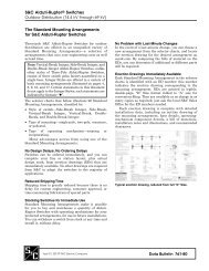
S & C E L E C T R I C C O M P A N YSelecting a Disconnect, Cutout, Power Fuse, Fuse Limiter, or Dropout RecloserHere’s what to look for when selecting a disconnect,cutout, power fuse, fuse limiter, or dropout recloser tobe switched with Loadbuster:h There must be an attachment hook at the upper (jaw)end of the device, over which Loadbuster’s anchorcan be hooked; and a pull-ring on the device’s switchblade or fuse tube which can be readily engagedwith Loadbuster’s pull-ring hook and held fast by thepull-ring latch.h The device must mechanically coordinate withLoadbuster’s operating sequence such that (a) engagementof Loadbuster will not cause or allow the switchQuantitative Requirements for Devices Qualifying for Use with Loadbusterblade or fuse tube to drop open prematurely and (b)the attachment hook will keep Loadbuster positivelyanchored until tripping occurs, while (c) permittingeasy removal of Loadbuster whether the openingstroke has been completed or whether, for any reason,the device being switched has been reclosed afterpartial (incomplete) opening.h The device must be capable of easy, positive manipulationwith Loadbuster from all practical angles anddirections—and in all mounting positions intendedor the device—while maintaining the minimummechanical and electrical requirements, as listed in thetable below.I II III1 IV6 V7LoadbusterCatalog NumberDisconnect, Cutout,Power Fuse, Fuse Limiter,or Dropout RecloserApplication—Max SystemOperating Voltage,Three-PhaseMinimum Dry Withstand VoltagesAcross External Disconnect Gap260-Hertz3–atTime of Tripping4CapacitanceSwitching Test5–Circuit VoltageSuggested MinimumExternal DisconnectGap Separation2at Time of Tripping4Suggested MinimumExternal DisconnectGap Separation2with LoadbusterFully Extended to“Latched-Open” PositionkV kV, RMS kV, RMS Inches (mm) Inches (mm)5<strong>30</strong>0R3 9 18 9 3¹⁄₂ (89) 4 (102)5<strong>30</strong>0R3 & 5400R3 15 <strong>30</strong> 15 3¹⁄₂ (89) l 3⁷⁄₈ (99)d 4¹⁄₂ (115)l 5 (127)d5<strong>30</strong>0R3 & 5400R3 18 36 18 3⁷⁄₈ (99) 5 (127)5<strong>30</strong>0R3 & 5400R3 27 41 l 54d 20.5 l 27d 3⁷⁄₈ (99)d 4³⁄₄ (121)d 5 (127)l 6 (153)d5400R3 29 a 29 5¹⁄₄ (134) 6¹⁄₂ (166)5400R3 38 a 29 5¹⁄₄ (134) 6¹⁄₂ (166)1 Disconnects, cutouts, power fuses, fuse limiters, or dropout reclosers(while being switched with Loadbuster) must be capable of withstandingat least one of these tests without flashover, preferably with the mountingbracket or base of the device under test grounded. However, in the caseof devices with insulation just meeting minimum ANSI standards, it maybe necessary to test with mounting bracket or base floating. The specifiedvoltages are given for standard atmospheric conditions of temperature,barometric pressure, and humidity, and must be corrected for the existingatmospheric conditions at the time of test.2 Between all live parts of the combination of Loadbuster and disconnect,cutout, power fuse, fuse limiter, or dropout recloser for the mostunfavorable practical operating position of Loadbuster.3 These minimum voltages must be applied for a period of 10 seconds. Thevoltage shall be applied starting at 75% of the ultimate value and raised tothe listed test voltage at a constant rate such that the test voltage is reachedin not less than 5 seconds nor more than 10 seconds. An appropriatelycalibrated means must be used to measure the voltage.4 Tripped condition is simulated when Loadbuster Catalog Number5<strong>30</strong>0R3 is telescoped to 1⁷⁄₈ inches (48 mm) from “latched-open” position,or when Loadbuster Catalog Number 5400R3 is telescoped 1³⁄₈ inches(35 mm) from “latched-open” position.5 This test consists of interruption of a 0% PF leading capacitance currentof 2 to 5 amperes with Loadbuster used in the most unfavorable operatingposition. The test circuit is to be energized by a 60-hertz source at the voltagespecified. A test series of 20 successive operations must be performedwithout flashover across the external disconnect gap.6 These dimensions are approximately those required to meet thevoltages specified in Column III. They are based on designs where sharppoints, sharp edges, protrusions, etc., are avoided so that essentiallyrod-gap configuration is obtained on disconnect, cutout, power fuse,fuse limiter, or dropout recloser contacts. Sharp points, edges, etc., mayrequire minimum gaps measuring as much as 25% greater than the dimensionslisted to achieve the same dry withstand values.7 These dimensions permit Loadbuster to be removed without reducingthe gap below the values listed in Column IV, and should be maintainedafter circuit interruption (even though the transient recovery voltage maynot then be a factor) to provide margin for possible inattentive manipulationof Loadbuster.l Loadbuster Catalog Number 5<strong>30</strong>0R3.d Loadbuster Catalog Number 5400R3.a Loadbuster should not be subjected to sustained 60-hertz voltage ofthe value that would be required for this test. Only the “CapacitanceSwitching Transient” test (column at right) is applicable at this voltage.S&C ELECTRIC COMPANYSpecialists in <strong>Electric</strong> Power Switching and ProtectionOffices Worldwidewww.sandc.com • Telephone: (773) 338-1000 • Fax: (773) 338-3657Printed in U.S.A.
![Boletin Descriptivo 851-30S [Spanish, 3 MB, 12/20/2004]](https://img.yumpu.com/49573007/1/190x245/boletin-descriptivo-851-30s-spanish-3-mb-12-20-2004.jpg?quality=85)
![Boletin de Especificaciones 771-31S [Spanish, 2 MB, 8/30/2010]](https://img.yumpu.com/48742025/1/190x245/boletin-de-especificaciones-771-31s-spanish-2-mb-8-30-2010.jpg?quality=85)