Life Fitness Strength 8500 3-Stack Multi Gym ... - GymStore.com
Life Fitness Strength 8500 3-Stack Multi Gym ... - GymStore.com
Life Fitness Strength 8500 3-Stack Multi Gym ... - GymStore.com
- No tags were found...

Create successful ePaper yourself
Turn your PDF publications into a flip-book with our unique Google optimized e-Paper software.
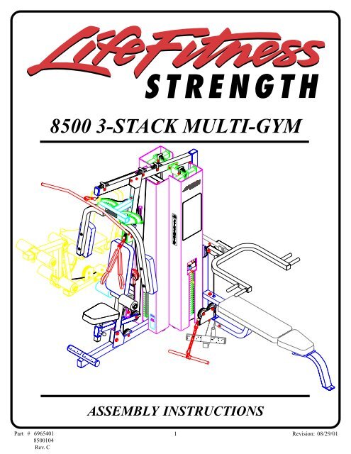
<strong>8500</strong> 3-STACK MULTI-GYMASSEMBLY INSTRUCTIONSPart # 6965401<strong>8500</strong>104Rev. C1Revision: 08/29/01
IMPORTANT NOTESPlease note:* Thank you for purchasing the LIFE FITNESS <strong>8500</strong> MULTI-GYM. Please read these instructionsthoroughly and keep them for future reference. This product must be assembled on a flat, levelsurface to assure its proper function.* We re<strong>com</strong>mend cleaning your product (pads and frame) on a regular basis, using warm soapywater. Touch-up paint can be purchased from your LIFE FITNESS customer service representativeat (800) 328-9714.There is a risk assumed by individuals who use this type of equipment. To minimize risk, pleasefollow these rules:1. Inspect equipment daily. Tighten all loose connections and replace worn parts immediately.Failure to do so may result in serious injury.2. Do not allow minors or children to play on or around this equipment.3. Exercise with care to avoid injury.4. If unsure of proper use of equipment, call your local LIFE FITNESS STRENGTH distributor orcall the LIFE FITNESS STRENGTH customer service department at (800) 328-9714.5. Consult your physician before beginning any exercise program.Tools Required for Assembly* Rubber mallet or hammer* 3/4” wrench, 9/16” wrench* Ratchet with 3/4” and 9/16” sockets* 5/32”, 3/16”, 7/32” Allen wrenches* Adjustable wrench* Tape measureBolt Length RulerNOTE: BOLT LENGTH IS MEASURED FROM THE UNDERSIDE OF THE HEAD OF THE BOLT.BOLT LENGTH RULER:BOLT LENGTH1/2 1/2 1/2 1/2 1/2 1/20 1 2 3 4 5 62
PARTS LISTKEY1234567891011121314151617181920212223242526272829303132333435363738394041424344454647484950515253545556575859PART #66171036779802662550266242026624302662290366230036623503662450266225036620903669180366924026623702666220366623036628302627530265234016765203676530367699036768003676790367690036769702676980367721026768803676850367692036965503687250267710036770102687170267683036770703677220167723016764901677310169624016773301695490167735013108002311610132023016284501638970166193016714601311600165947026651602686870261227023118401DESCRIPTIONREAR UPRIGHTLEG BACK PAD ADJUSTLEG BACK PAD SUPPORTBACK PAD ANGLE LEFTBACK PAD ANGLE RIGHTPEC ARM RIGHTPEC ARM LEFTPRESS ARMCALF/LOW ROWBEARING HOUSINGFLOATING PULLEY STOPSEAT SUPPORTPAD SUPPORTWOLFF SLEEVELEG EXT HANDLE RIGHTLEG EXT HANDLE LEFT2 X 8” PLATELAT BAR72-3/8” GUIDE RODPRESS G.R. SUPPORTLEG G.R. SUPPORTPEC G.R. SUPPORTLEG WT. STACK BASEPRESS WT. STACK BASEBASEPULLEY BRACKETCENTER PULLEY BRACKETPEC CAMFRONT UPRIGHTTOP BOOMREAR BASE LEGLEG CURL/EXTENSIONPAD SLEEVELEG FRAMESWIVEL PULLEY BRACKETPRESS ARM ADJUSTPRESS FRAMEPRESS BASE19-1/4” TUBE21-1/2” TUBE4 X 7” ROLLER PADLAT CABLE ASSEMBLYLEG CABLE ASSEMBLYPRESS CABLE ASSEMBLYAB CRUNCH CABLE ASSEMBLYPEC DEC CABLE ASSEMBLYWEIGHT STACK CUSHION4-1/2” PULLEYPILLOW BLOCK BEARING20 HOLE SELECTOR SHAFTLOW ROW CHROME BARU-PINHEAD PLATE1-1/4” SQ. RUBBER BUMPERFLOATING PULLEY BRACKET2 X 15-1/2” PLATE4-1/2 X 8” PLATE3/8 X 1/2” SPACER4” VINYL CAPQTY111111111111111111611111111211112111111181111182423113312121KEY60616263646566676869707172737475767778798081828384858687888990919293949596979899100101102103104105106107108109110111112113114115116118PART #6140701617700164120016466901695470366926016781601675770131038016480301602060131049016619501310960260759066214401640640166950013103302310330431025013114502310280231028073102502310280131028043202401310290131029333102922310291531029063202101310291031029183102917320210732021056780101678000167803016780201678040167806016780501621450167038016189501638230163758016779703677950367796013102909310840468270016122704DESCRIPTION1 X 1” GLIDE2-1/2 X 5-1/2 NON-SKID STRIP3/8 X 2-3/4” DIA. SPRING PIN1/2 X 3-1/2” DIA. SPRING PINAB PULLEY PLATE3 X 2” END CAP1/2 X 7-7/8” SPRING PIN2-7/8 X 1” CABLE CLIP5/16” SNAP LINK3/8” FLANGE SPACER1/2” FLANGE BEARING3/4” FLANGE BEARING3/4” SLEEVE BEARING1/2” PAL NUT12 LINK CHAINWEIGHT STACK PINHINGE TAB3/4” DIA. TAPPED SHAFT13/16” SHAFT COLLAR1-5/16” SHAFT COLLAR3/8” WASHER3/8” LOCK WASHER3/8” LOCK NUT3/8” LOW HEIGHT LOCK NUT1/2” WASHER1/2” LOCK NUT1/2” LOW HEIGHT LOCK NUT3/8 X 1” BTTN HD CAP SCREW3/8 X 1-1/4” BOLT3/8 X 2” BOLT3/8 X 2-3/4” BOLT3/8 X 3-1/4” BOLT3/8 X 4” BOLT1/2 X 1-1/4” BOLT1/2 X 3” BOLT1/2 X 3-1/4” BOLT1/2 X 4” BOLT1/2 X 6-1/2” BOLT1/2 X 7-1/2” BOLTPEC ARM PADPRESS SEAT PADPRESS BACK PADLEG SEAT PADLEG BACK PADPEC SEAT PADPEC BACK PADWEIGHT PLATEWEIGHT PLATE LABELS (LBS.)WEIGHT PLATE LABELS (1-25)WEIGHT PLATE BUSHING (10 CT)AB CRUNCH STRAPLEG SHROUDPEC SHROUDPRESS SHROUD3/8 X 1” BOLT3/8 X 3” COUNTERSUNK BOLT2-7/8 X 2-1/4” CABLE CLIP1/4” SPACERQTY5461221124244621134168675413212484151416164278102121111116011121111122843
231/2 X 3-1/4” 9525612485FIGURE 1STEP 1:• LOOSELY assemble the LEG WEIGHT STACK BASE (23) and the PRESS WEIGHT STACK BASE (24) to the BASE (25) using two1/2 X 3-1/4” BOLTS (95) and two 1/2” LOCK NUTS (85) as shown in FIGURE 1.• Apply two NON-SKID STRIPS (61) to the BASE (25) as shown in FIGURE 1.1/2 1/2 1/2 1/2 1/2 1/20 1 2 3 4 5 64
96 1/2 X 4””3084858595 1/2 X 3-1/4”1298584852594 1/2 X 3”FIGURE 2STEP 2:95 1/2 X 3-1/4”• LOOSELY assemble the FRONT UPRIGHT (29) to the BASE (25) using two 1/2 X 3-1/4” BOLTS (95) and two 1/2” LOCK NUTS (85)as shown in FIGURE 2.• LOOSELY assemble the REAR UPRIGHT (1) to the BASE (25) using one 1/2 X 3” BOLT (94), two 1/2” WASHERS (84), and one 1/2”LOCK NUT (85) as shown in FIGURE 2.• LOOSELY assemble the TOP BOOM (30) to the REAR UPRIGHT (1) using two 1/2 X 4” BOLTS (96), two 1/2” WASHERS (84), andone 1/2” LOCK NUT (85) as shown in FIGURE 2.• LOOSELY assemble the TOP BOOM (30) to the FRONT UPRIGHT (29) using two 1/2 X 3-1/4” BOLTS (95) and two 1/2” LOCK NUTS(85) as shown in FIGURE 2.TIGTEN ALL LOOSE FRAME CONNECTIONS MADE TO THIS POINT!5
731459376252FIGURE 5STEP 5:• SECURELY assemble one 3/8 X 2-3/4” SPRING PIN (62) to the WOLFF SLEEVE (14) as shown in FIGURE 5.• Assemble one U-PIN (52) to the WOLFF SLEEVE (14) using one 1/2” PAL NUT (73).• Slide one 4” VINYL SLEEVE (59) onto the U-PIN (52) as shown in FIGURE 5.• CAREFULLY slide the WOLFF SLEEVE (14) onto the PRESS FRAME (37) until the SPRING PIN engages in one of the holes.1/2 1/2 1/2 1/2 1/2 1/20 1 2 3 4 5 68
94 1/2 X 3”381848586 1/2” LOW HEIGHT94 1/2 X 3”35848525FIGURE 6STEP 6:• SECURELY assemble the PRESS BASE (38) to the BASE (25) using two 1/2 X 3” BOLTS (94), two 1/2” WASHERS (84), and two 1/2”LOCK NUTS (85), and to the REAR UPRIGHT (1) using one 1/2 X 3” BOLT (94), one 1/2” WASHER (84), and one 1/2” LOCK NUT(85) as shown in FIGURE 6.• Assemble the SWIVEL PULLEY BRACKET (35) to the PRESS BASE (38) using one 1/2” LOW HEIGHT LOCK NUT (86) as shown inFIGURE 6. (NOTE: Securely tighten, then back nut off 1/4 turn to allow the SWIVEL PULLEY BRACKET to rotate freely.)9
94 1/2 X 3”84115 3/8 X 3” COUNTER SUNK37578485388082FIGURE 7STEP 7:• SECURELY assemble the PRESS FRAME (37) to the PRESS BASE (38) using one 1/2” X 3” BOLT (94), two 3/8 X 3” COUNTERSUNK BOLTS (115),one 4-1/2” X 8” PLATE (57), two 1/2” WASHERS (84), two 3/8” WASHERS (80), one 1/2” LOCK NUT (85), and two 3/8” LOCK NUTS (82). (NOTE:Make sure 3/8” countersunk bolts are facing down.) See FIGURE 7.1/2 1/2 1/2 1/2 1/2 1/20 1 2 3 4 5 610
101803/8 X 1-1/4” 8851/2”LOW86 HEIGHT54841/2 X 1-1/4” 9337116851004381476803/8 X 1-1/4” 8897 1/2 X 6-1/2”FIGURE 8STEP 8:• Slide two HINGE TABS (76) onto the WOLFF SLEEVE (14) and SECURELY attach PRESS SEAT PAD (100) using two 3/8 X 1-1/4”BOLTS (88) and two 3/8” WASHERS (80). (NOTE: The “hinge” part of the HINGE TAB (76) should face upward as shown inFIGURE 8.)• Slide the RIGHT BACK PAD ANGLE (5) and LEFT BACK PAD ANGLE (4) onto the WOLFF SLEEVE (14) and attach the PRESSBACK PAD (101) using four 3/8 X 1-1/4” BOLTS (88) and four 3/8” WASHERS (80). See FIGURE 8.• SECURE two 2 X 15-1/2” PLATES (56) to the RIGHT BACK PAD ANGLE (5) and the LEFT BACK PAD ANGLE (4) using two 1/2 X 1-1/4” BOLTS (93), two 1/2” WASHERS (84) and two 1/2” LOW HEIGHT LOCK NUTS (86). (NOTE: SECURE lock nuts, then back off1/4 turn.)• SECURE the 2 X 15-1/2” PLATES (56) to the bushing in the PRESS BASE (38) using one 1/2 X 6-1/2” BOLT (97) and one 1/2” LOCK NUT(85) as shown in FIGURE 8.• Apply one 1-1/4” RUBBER BUMPER (54) to the PRESS FRAME (37) where the back of the pad <strong>com</strong>es in contact with the frame.11
18236498091 3/8 X 3-1/4”858438996 1/2 X 4”61FIGURE 9STEP 9:• LOOSELY assemble the PRESS ARM ADJUST (36) to the REAR UPRIGHT (1) using two 1” PILLOW BLOCK BEARINGS (49), four3/8 X 3-1/4” BOLTS (91), four 3/8” WASHERS (80), and four 3/8” LOCK NUTS (82). (NOTE: Assemble PILLOW BLOCKS (49) so theset screws are on the outside, this will allow more adjustment.) See FIGURE 9.• Center PRESS ARM ADJUST (36) to line up with the post on the PRESS BASE (38) and securely tighten set screws on the PILLOW BLOCKBEARINGS (49). See FIGURE 9.• Adjust the PILLOW BLOCK BEARINGS (49) until the PRESS ARM ADJUST (36) is level, then SECURELY tighten bolts.• SECURELY assemble CALF/LOW ROW (9) to the PRESS BASE (38) using two 1/2 X 4” BOLTS (96), two 1/2” WASHERS (84), and two1/2” LOCK NUTS (85) as shown in FIGURE 9.• Apply two NON-SKID STRIPS (61) to the CALF/LOW ROW (9) as shown in FIGURE 9.1/2 1/2 1/2 1/2 1/2 1/20 1 2 3 4 5 612
3682708486 1/2” LOW HEIGHT890 3/8 X 2-3/4”6398 1/2 X 7-1/2”FIGURE 10STEP 10:• SECURELY assemble one 1/2 X 3-1/2” SPRING PIN (63) to the PRESS ARM (8) as shown in FIGURE 10.• SECURELY assemble the PRESS ARM (8) to the PRESS ARM ADJUST (36) using one 1/2 X 7-1/2” BOLT (98), two 1/2” WASHERS (84),two 1/2” FLANGE BEARINGS (70), and one 1/2” LOW HEIGHT LOCK NUT (86). (NOTE: SECURELY tighten, then back nut off 1/4to allow the PRESS ARM to rotate freely.)• SECURELY assemble four 3/8 X 2-3/4” BOLTS (90) and four 3/8” LOCK NUTS (82) to the PRESS ARM ADJUST (36) as sjown in FIGURE 10.13
STEP 13:• SECURELY assemble one 2 X 8” PLATE (17) to the LEG SEATPAD (102) using two 3/8 X 1-1/4” BOLTS (88) and two 3/8”WASHERS (80). See FIGURE 13.• Apply one 1-1/4” RUBBER BUMPER (54) to the 2 X 8” PLATE(17) as shown in FIGURE 13.5488 3/8 X 1-1/4”8017102FIGURE 131026676348088 3/8 X 1-1/4”FIGURE 14STEP 14:• SECURELY assemble the LEG SEAT PAD (102) to the HINGE TABS (76) using two 3/8 X 1-1/4” BOLTS (88) and two 3/8” WASHERS(80). See FIGURE 14.• SECURELY assemble one 1/2 X 7-7/8” SPRING PIN (66) to the LEG FRAME (34) as shown in FIGURE 14.15
31/2 X 6-1/2” 9722603/8” BLACK81 LOCKWASHER703/8 X 1” BUTTON HEAD 878532717754NOTE: TIGHTEN BOTH ATTHE SAME TIME!34FIGURE 15STEP 15:• SECURELY assemble one 1 X 1” GLIDE (60) to the angle on the BACK PAD ADJUST (2) as shown in FIGURE 15.• Assemble LEG BACK PAD ADJUST (2) and LEG BACK PAD SUPPORT (3) to the LEG FRAME (34) using one 1/2 X 6-1/2” BOLT (97),two 1/2” FLANGE BEARINGS (70), one 1/2” LOCK NUT (85) as shown in FIGURE 15. (NOTE: Securely tighten, then back nut off 1/4turn to allow the two parts to rotate freely.)• SECURELY assemble the LEG CURL/EXTENSION (32) to the LEG FRAME (34) using two 3/4” FLANGE BEARINGS (71), one 3/4”TAPPED SHAFT (77), two black 3/8” LOCK WASHERS (81), and two 3/8 X 1” BLACK BUTTON HEAD CAP SCREWS (87). (NOTE:Both CAP SCREWS must be tightened at the same time using two allen wrenches.)• SECURELY assemble one 1-1/4” RUBBER BUMPER (54) to the contact point on the LEG FRAME (34) as shown in FIGURE 15.1/2 1/2 1/2 1/2 1/2 1/20 1 2 3 4 5 616
3/8 X 3-1/4” 91380794110339234FIGURE 16STEP 16:• SECURELY assemble the LEG BACK PAD (103) to the LEG BACK PAD ADJUST (2) and the LEG BACK PAD SUPPORT (3) usingfour 3/8 X 3-1/4” BOLTS (91) and four 3/8” WASHERS (80). See FIGURE 16.• SECURELY assemble two 4 X 7” ROLLER PADS (41) to the LEG FRAME (34) using one 19-1/4” TUBE (39) and two 1-5/16” SHAFTCOLLARS (79). SECURELY tighten set screws on SHAFT COLLARS (79). See FIGURE 16.17
82328485653387 3/8 X 1-1/4”BUTTONHEAD23624179341/2 X 4” 96FIGURE 17STEP 17:• SECURELY assemble two 3/8 X 2-3/4” SPRING PINS (62) to the PAD SLEEVES (33) as shown in FIGURE 17.• Assemble four ROLLER PADS (41) to the PAD SLEEVES (33) using four 1-5/16” SHAFT COLLARS (79). SECURELY tighten setscrews on SHAFT COLLARS (79). See FIGURE 16.• Slide PAD SLEEVES (33) over LEG CURL/EXTENSION (32) until the spring pin pops into the holes. (NOTE: PAD SLEEVES should be facingas shown in FIGURE 17.)• SECURELY assemble two 3/8 X 1” BUTTON HEAD CAP SCREWS (87) and two 3/8” LOCK NUTS (82) to the last holes in the LEGCURL/EXTENSION (32) as shown in FIGURE 17.• Insert two 3 X 2” END CAPS (65) into the ends of the LEG CURL/EXTENSION (32) as shown in FIGURE 17.• SECURELY assemble LEG FRAME (34) to the LEG WEIGHT STACK BASE (23) using two 1/2 X 4” BOLTS (96), two 1/2” WASHERS(84), and two 1/2” LOCK NUTS (85). See FIGURE 17.STEP 18:109• Snap two WEIGHT PLATE BUSHINGS (109) into the top side of allsixty WEIGHT PLATES (106) as shown in FIGURE 18.1061/2 1/2 1/2 1/2 1/2 1/20 1 2 3 4 5 618FIGURE 18
7819533/8” LOCKWASHER 813/8 X 1-1/4” 8850TWO PER SIDEON THIS STACK ONLY!10623TWOPERSIDE!107 108242547FIGURE 19STEP 19:• Insert the two GUIDE RODS (19) into the BASE (25) as shown in FIGURE 19. Lubricate the GUIDE RODS (19) with a slicon or teflonspray that is available at most hardware stores.• Slide two WEIGHT STACK CUSHIONS (47) down over the GUIDE RODS (19). See FIGURE 19.• Using EXTREME CARE slide twenty WEIGHT PLATES (106) down over the GUIDE RODS (19) with the the key-hole facing asshown in FIGURE 19.• SECURELY assemble the WEIGHT STACK SHAFT (50) to the HEAD PLATE (53) using one 3/8 X 1-1/4” BOLT (88) and one 3/8”BLACK LOCK WASHER (81). (Note: The bolt hole in the HEAD PLATE (53) should be on top.)• Carefully Slide the HEAD PLATE ASSEMBLY down over the GUIDE RODS (19) onto the weight stack as shown.• Apply one set of WEIGHT STACK LABELS - LBS. OR NUMBERED 1-20 (107) (108) to each WEIGHT PLATE (106). See FIGURE 19.• Slide two 13/16” SHAFT COLLARS (78) over the GUIDE RODS (19) as shown in FIGURE 19.• REPEAT the above steps to assemble the weight stacks on the PRESS WEIGHT STACK BASE (24) and the LEG WEIGHT STACKBASE (23). (NOTE: Use four WEIGHT STACK CUSHIONS (47) (two per guide rod!) on the LEG WEIGHT STACK BASE (23)as shown in FIGURE 19.)19
852130201995 1/2 X 3-1/4”FIGURE 20STEP 20:• Slide the PRESS GUIDE ROD SUPPORT (20) and LEG GUIDE ROD SUPPORT (21) over their respective GUIDE RODS (19) andSECURELY assemble them to the TOP BOOM (30) using two 1/2 X 3-1/4” BOLTS (91) and two 1/2” LOCK NUTS (85) as shown inFIGURE 20.3/8 X 2-3/4” 9080212083 3/8” LOW HEIGHT22307819FIGURE 21STEP 21:• Slide the PEC GUIDE ROD SUPPORT (22) onto the GUIDE RODS (19) and SECURELY assemble the PEC GUIDE ROD SUPPORT (22)to TOP BOOM (30) using two 3/8 X 2-3/4” BOLTS (90), four 3/8” WASHERS (80), and two 3/8” LOW HEIGHT LOCK NUTS (83). SeeFIGURE 21.• Slide the 13/16” SHAFT COLLARS (78) to the top of the GUIDE ROD SUPPORTS (20,21,22) and SECURELY tighten the SHAFTCOLLARS set screws. See FIGURE 21.1/2 1/2 1/2 1/2 1/2 1/20 1 2 3 4 5 620
464445424321
42LATCABLE8255691148FIGURE 25STEP 25:2590 3/8 X 2-3/4”• Route the LAT CABLE (42) around the pulley in FLOATING PULLEY STOP (11) and the FLOATING PULLEY BRACKET (55) as shown inFIGURE 25. (NOTE: The CABLE CLIPS may need to be loosened.)• SECURELY assemble two 4-1/2” PULLEYS (48) into the slots of the BASE (25) using two 3/8 X 2-3/4” BOLTS (90), four 3/8” FLANGESPACERS (69), and two 3/8” LOCK NUTS (82). (NOTE: Loop the cable around each pulley prior to inserting it in the the slot.)48LAT CABLE 4282306911690 3/8 X 2-3/4”FIGURE 26STEP 26:• Route the threaded end of the LAT CABLE (42) through the TOP BOOM (30) and down through the PEC GUIDE ROD SUPPORT (22) asshown in FIGURE 26.• SECURELY assemble one 4-1/2” PULLEY (48) into the rear slot of the TOP BOOM (30) using one 3/8 X 2-3/4” BOLT (90), two 3/8” FLANGESPACERS (69), one 2-7/8” X 2-1/4” CABLE CLIP (116) and one 3/8” LOCK NUT (82). (NOTE: Loop the cable around the pulley prior to insertingit in the the slot.)23
42LATCABLE5053FIGURE 27STEP 27:• Screw the threaded end of the LAT CABLE (42) approximately 1” into the end of the SELECTOR SHAFT (50) of the HEAD PLATE (53) asshown in FIGURE 27.STEP 28:273/8 X 2” 89• LOOSELY assemble two 4-1/2” PULLEYS (48)to the CENTER PULLEY BRACKET (27) usingtwo 3/8 X 2” BOLTS (89), two 2-7/8” CABLECLIPS (67), two 3/8” WASHERS (80), and two3/8” LOCK NUTS (82). See FIGURE 28.67828048FIGURE 281/2 1/2 1/2 1/2 1/2 1/20 1 2 3 4 5 624
488246 PEC CABLE3/8 X 2” 8967FIGURE 2926STEP 29:• Assemble one 4-1/2” PULLEY (48) around the PEC DEC CABLE (46) and to the PULLEY BRACKET (26) using one 3/8 X 2” BOLT (89),two 2-7/8 X 1” CABLE CLIPS (67) and one 3/8” LOCKNUT (82) as shown in FIGURE 29.STEP 30:• Slide the ends of the PEC DEC CABLE(46) into the bushings on the PEC CAMS(28) as shown on FIGURE 30.• Lay the PEC DEC CABLE (46) over thepulleys and under the cable retaining clipsin the CENTER PULLEY BRACKET (27)as shown in FIGURE 30. (NOTE: Securelytighten the pulley connections in theCENTER PULLEY BRACKET (27).The cable retaining clips should be at approximatelya 45° angle.)274628PEC 46CABLEFIGURE 3025
11745 AB CABLE80SEE DETAIL 31486995 3/8 X 3-1/4”118FIGURE 31 DETAIL 31STEP 31:• Securely assemble the ball end of the AB CABLE (45) and one 4-1/2” PULLEY (48) to the FRONT UPRIGHT (29) using two AB PULLEYPLATES (117), two 3/8 X 3-1/4” BOLTS (91), four 1/4” SPACERS (118), two 3/8” FLANGE SPACERS (69), two 3/8” WASHERS (80) andfour 3/8” LOCKNUTS (82) . (NOTE: The AB CABLE (45) should be routed underneath the retaining bolt as shown in DETAIL 3.)STEP 32:• Route the AB CABLE (45) around the FLOATING PULLEYBRACKET (55) using one 4-1/2” PULLEY (48), one 3/8 X 2”BOLT (89), two 2-7/8 X 1” CABLE CLIPS (67), two 3/8” LOCKNUTS (82). See FIGURE 32.• Screw the threaded end of AB CABLE (45) approximately 1” intothe end of the PULLEY BRACKET (26) and tighten jam nut securelyas shown in FIGURE 32.8226AB CABLE 456755IMPORTANT! Make sure the cables are runningin the grooves of all pulleys.3/8 X 2” 89FIGURE 321/2 1/2 1/2 1/2 1/2 1/20 1 2 3 4 5 626
44374844 PRESS CABLE82803589 3/8 X 2”FIGURE 33STEP 33:• SECURE the ball end of the PRESS CABLE (44) and two 4-1/2” PULLEYS (48) to the SWIVEL PULLEY BRACKET (35) using two 3/8X 2” BOLTS (89), four 3/8” WASHERS (80), and two 3/8” LOCK NUTS (82) as shown in FIGURE 33. (NOTE: Loop the cable aroundthe pulleys prior to inserting it into the SWIVEL PULLEY BRACKET.)• Route the threaded end of the PRESS CABLE (44) through the large hole in the PRESS FRAME (37) as shown in FIGURE 33.27
FIGURE 34STEP 34:90 3/8 X 2-3/4”92 3/8 X 4”92 3/8 X 4”368269116 82695880444838• Route the threaded end of the PRESSCABLE (44) around one 4-1/2” PULLEY(48) and SECURELY assemble the pulleyto the front slot of the PRESS ARM AD-JUST (36) using one 3/8 X 2-3/4” BOLT(90), two 3/8” FLANGE SPACERS (69),and one 3/8” LOCK NUT (82) as shown inFIGURE 34. (NOTE: Loop the cable overthe pulley prior to inserting it into theslot.)• Route PRESS CABLE (44) through the slot inthe PRESS BASE (38) then SECURELY assembleone 4-1/2” PULLEY (48) to thePRESS BASE (38) using two 3/8 X 4”BOLTS (92), two 2-7/8 X 2-1/4” CABLECLIPS (116), two 3/8” FLANGE SPACERS(69), two 3/8 X 1/2” SPACERS (58), two 3/8” WASHERS (80), and two 3/8” LOCKNUTS (82) as shown in FIGURE 34.(NOTE:Make sure the cable is routed betweenthe pulley and the CABLE RETAIN-ING BOLT.)• Route the PRESS CABLE (44) around one4-1/2” PULLEY (48) and SECURELY assemblethe pulley to the rear slot of thePRESS ARM ADJUST (36) using one 3/8X 2-3/4” BOLT (90), two 3/8” FLANGESPACERS (69), and one 3/8” LOCK NUT(82) as shown in FIGURE 34. (NOTE:Loop the cable over the pulley prior toinserting it into the slot.)STEP 35:• SECURE the PRESS CABLE (44) and two 4-1/2”PULLEYS (48) to the vertical flats on the PRESS BASE(38) and on the PRESS WEIGHT STACK BASE (24)using two 3/8 X 2” BOLTS (89), two 2-7/8” CABLECLIPS (67) two 3/8” WASHERS (80), and two 3/8”LOCK NUTS (82) as shown in FIGURE 35. (NOTE:The PRESS CABLE (44) should be routedunderneath the short leg of the CABLE CLIP. Also,the CABLE CLIPS should be positioned straightdown to function properly.)89 3/8 X 2”24808244 PRESSCABLEFIGURE 354867381/2 1/2 1/2 1/2 1/2 1/20 1 2 3 4 5 628
FIGURE 364869823/8 X 2-3/4” 902011644 PRESS CABLESTEP 36:• SECURE the PRESS CABLE (44) and one 4-1/2” PULLEY (48) to the PRESS GUIDE ROD SUPPORT (20) using one 3/8 X 2-3/4”BOLT (90), two 3/8” FLANGE SPACERS (69), one 2-7/8 X 2-1/4” CABLE CLIP (116) and one 3/8” LOCK NUT (82) as shown inFIGURE 36. (NOTE: Loop the cable around the pulleys prior to inserting it into the PRESS GUIDE ROD SUPPORT.)PRESS 44CABLE5053STEP 37:• Screw the threaded end of the PRESS CABLE (44) approximately 1” into the end of the SELECTOR SHAFT (50) of the HEAD PLATE (53)as shown in FIGURE 37.29
89LEG CABLE 4332 83LOWHEIGHTDO NOT OVERTIGHTEN!FIGURE 38STEP 38:• SECURE the swivel on the LEG CABLE (43) to the tab on the LEG EXT/CURL (32) using one 3/8 X 2” BOLT (89) and one 3/8” LOWHEIGHT LOCK NUT (83) as shown in FIGURE 38. (NOTE: Do not overtighten! Swivel clevis should rotate freely.)1/2 1/2 1/2 1/2 1/2 1/20 1 2 3 4 5 630
4834828043 LEG CABLE803/8 X 2” 8967FIGURE 39STEP 39:• Route the LEG CABLE (43) through the vertical and horizontal brackets on the LEG FRAME (34) as shown in FIGURE 39.• SECURELY assemble one 4-1/2” PULLEY (48) to the vertical bracket on the LEG FRAME (34) using one 3/8 X 2” BOLT (89), two3/8” WASHERS (80), and one 3/8” LOCK NUT (82) as shown in FIGURE 39.• SECURELY assemble one 3/8 X 2” BOLT (89), two 3/8” WASHERS (80), and one 3/8” LOCK NUT (82) to the vertical bracket as shown inFIGURE 39. (Make sure CABLE is running over 3/8 X 2” RETAINING BOLT.)• SECURELY assemble one 4-1/2” PULLEY (48) to the horizontal bracket on the LEG FRAME (34) using one 3/8 X 2” BOLT (89), one3/8” WASHER (80), one 2-7/8” CABLE CLIP (67), and one 3/8” LOCK NUT (82) as shown in FIGURE 39. (NOTE: Before tightening,make sure CABLE CLIP (67) is positioned as shown in FIGURE 39.)IMPORTANT! Make sure the cables are runningin the grooves of all pulleys.31
4843 LEGCABLE23 8280673/8 X 2” 89FIGURE 40STEP 40:• Route the threaded end of the LEG CABLE (43) under the leg weight stack and throught the vetical bracket on the LEG WEIGHTSTACK BASE (23) as shown in FIGURE 40.• Assemble one 4-1/2” PULLEY to the vertical bracket on the WEIGHT STACK BASE (23) using one 3/8 X 2” BOLT (89),one 2-7/8 X 1”CABLE CLIP (67), two 3/8” WASHERS (80), and one 3/8” LOCK NUT (82) . (NOTE: Loop the cable under the pulley prior to inserting itinto the slot.)48LEG CABLE 431162182693/8 X 2-3/4” 90FIGURE 41STEP 41:• SECURE the LEG CABLE (43) and one 4-1/2” PULLEY (48) to the LEG GUIDE ROD SUPPORT (21) using one 3/8 X 2-3/4” BOLT(90), two 3/8” FLANGE SPACERS (69), one 2-7/8 X 2-1/4” CABLE CLIP (116)and one 3/8” LOCK NUT (82) as shown in FIGURE 41.(NOTE: Loop the cable around the pulleys prior to inserting it into the LEG GUIDE ROD SUPPORT.)1/2 1/2 1/2 1/2 1/2 1/20 1 2 3 4 5 632
FIGURE 42LEG CABLE 435053STEP 42:• Screw the threaded end of the LEG CABLE (43) approximately 1” into the end of the SELECTOR SHAFT (50) of the HEAD PLATE (53)as shown in FIGURE 42.STEP 43:• Perform the following to all three WEGHT STACKS:53• Insert one WEIGHT STACK PIN (75) into each weight stack on the <strong>8500</strong>GYM as shown in FIGURE 43.106• If upon <strong>com</strong>pletion of assembly, the HEAD PLATE (53) does not sit on topof the first WEIGHT PLATE (106), push the HEAD PLATE (53) down,insert the WEIGHT STACK PIN (75) and perform several repetitions at thepress station. This will relax the cable system and prevent the HEADPLATE (53) from lifting up.• If after <strong>com</strong>pleting previous step, the HEAD PLATE (53) still does not siton top of the first WEIGHT PLATE (106) or if there is excess slack in thecable system, adjust the threaded end of the CABLE accordingly andretighten the jam nuts.75• If there is excess slack in the AB or PEC DEC cable system, adjust thethreaded end of the AB CABLE (45) accordingly and retighten the jamnut.33FIGURE 43
FIGURE 44111114 3/8 X 1”11380113112STEP 44:• SECURELY assemble the PRESS SHROUD (113-has press exercise placard ) to the PRESS GUIDE ROD SUPPORT (20) and the PRESSWEIGHT STACK BASE (24) using four 3/8” X 1” BOLTS (114) and four 3/8” WASHERS (80). See FIGURE 44.• SECURELY assemble the PEC SHROUD (112-has warning label in right corner ) to the PEC GUIDE ROD SUPPORT (22) and the BASE(25) using using four 3/8” X 1” BOLTS (114) and four 3/8” WASHERS (80). See FIGURE 44.• SECURELY assemble the LEG SHROUD (111-has leg exercise placard ) to the LEG GUIDE ROD SUPPORT (21) and the LEG WEIGHTSTACK BASE (23) using four 3/8” X 1” BOLTS (114) and four 3/8” WASHERS (80). See FIGURE 44.1/2 1/2 1/2 1/2 1/2 1/20 1 2 3 4 5 634
681868110516874FIGURE 45STEP 45:• Attach the LAT BAR (18) to the ball end of lat cable using one 5/16” SNAP LINK (68).• Attach the AB CRUNCH STRAP (110) to the ball end of cable using one 5/16” SNAP LINK (68).• Attach the LOW ROW BAR (51) to the ball end of press cable using two 5/16” SNAP LINKS (68) and one 12 LINK CHAIN (74).Thank you for purchasing the <strong>Life</strong><strong>Fitness</strong> <strong>8500</strong> 3-STACK MULTI-GYM. If unsure of proper use of equipment,call your local <strong>Life</strong><strong>Fitness</strong> distributor or call the <strong>Life</strong><strong>Fitness</strong> customer service department at (800) 328-9714.35