ABS I Diagnostics - K100.biz
ABS I Diagnostics - K100.biz
ABS I Diagnostics - K100.biz
- No tags were found...

Create successful ePaper yourself
Turn your PDF publications into a flip-book with our unique Google optimized e-Paper software.
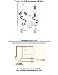
17/11/2010 <strong>ABS</strong> I <strong>Diagnostics</strong><strong>ABS</strong> I Diagnostic MethodsBy Brian Curry corrected by Gianni Becattini, November 2010September 1998Generally when the <strong>ABS</strong> lights start flashing, people start seeing dollar signs since there seems to be very littleinfo on it out there, and what is there, has you testing using the BIG DOLLAR $$$ BMW test tool.This is some info o n how to find o ut what is c ausing the fault using a Volt O hm Meter (VOM) a nd then howto investigate and narrow it down more using that same VOM. This is written based on <strong>ABS</strong> I. <strong>ABS</strong> II issimilar, but has different codes.The fault code is indicated at the diagnostic connector that the BMW tool connects to. On my K75 thediagnostic connector is located on the bike right side under the side panel. It plugs into a blue "blank"connector tiewrapped to the frame. There are three pins on this connector. I was not able to detect anyvoltage on the outer, number 1 and 3 pins.The center, number 2, pin is where the fault codes are indicated. This pin has about 0.5 to 0.75 volts on itwith the bike shut off. When the ignition is turned on, the voltage rises to a bout 1 0 volts. W hen a ll is well, itstays a t 1 0 volts. However, if there is a fault, it d rops towards zero (pulses) in a periodic manner. When thereis a fault, every so often, the voltage pulses downwards toward 0 volts. The number of pulses, indicates thefault number. In o ther words, if it p ulses d ownwards 4 times, that indicates that there is a problem with thefault code number 4 items. The pulsing also occurs when the ignition is first turned on and the voltage is risingto ~ 10 volts, b ut it is e asier to spot when it o ccurs p eriodically la ter. I was a ble to see the p ulses e asily usingan analog meter. It can also be seen using a digital meter. There is not enough current available to light a light.I tried.With the fault code number, troubleshooting can proceed.First the <strong>ABS</strong> plug is numbered as shown below. Yes, it is a PITA to get the <strong>ABS</strong> brain out and the plugdisconnected from the <strong>ABS</strong> I but some tests have to be done from there. With the pin sockets toward you,and the cable on the right, it is numbered from the right to the left, bottom and then top. This is important.25 14____________________________________| \_______| _______ Cable|____________________________________/13 1System voltage test. Power is supplied on Pin 15, and Pin 14 is ground. Connect to them, and confirm thatwhen the ignition is turned on, the voltage is the same as at the battery.Fault Code 1 - Front Pressure Modulator<strong>ABS</strong> connector pins of interest 6,9,10Test ValueresistanceResistance 6-9~4.48 k-ohmsResistance 6-10~16.7 K-ohms (Error: read 174k!)ibmwr.org/ktech/abs-diagnostics.shtml 1/5
17/11/2010 <strong>ABS</strong> I <strong>Diagnostics</strong>Resistance 9-10~19.5 K-ohms (Error: read 174k!)If an open is indicated, check the wires from the brain plug to the Modulator plug. If those connections areOK, the modulator is bad.Remove the <strong>ABS</strong> relay in the electrical box under the tank. The relay is at the front of the box, on the leftside, just beside where the front wiring harness enters the box. Measure resistance from the <strong>ABS</strong> relay socketto ground. Measure from 87 to frame ground. It should measure 17.4 K-ohms.Socket:30_________| __ || |87 | | __ | 86| | __ ||_________|85Again, if it is open circuit check from the socket to the Modulator plug. Then check from Terminal 31 of theModulator to ground. Again, if the wiring is good, the mo dulator is b ad.With the ignition off, the <strong>ABS</strong> relay socket connection Pin 30 should be the same as the battery voltage. Ifnot, check that connection point is secure, and the red wire from the battery to connection point 30.Fault Code 2 - Rear Pressure Modulator<strong>ABS</strong> connector pins of interest 7,11,12Test ValueresistanceResistance 7-11~4.48 K-ohmsResistance 7-12~16.7 K-ohms (Error: read 174k!)Resistance 11-12~19.5 K-ohms (Error: read 174k!)If an open is indicated, check the wires from the brain plug to the Modulator plug. If those connections areOK, the modulator is bad.Remove the <strong>ABS</strong> relay in the electrical box under the tank. The relay is at the front of the box, on the leftside, just beside where the front wiring harness enters the box. Measure resistance from the <strong>ABS</strong> relay socketto ground. Measure from 87 to frame ground. It should measure 17.4 K-ohms.Again, if it is open check from the socket to the Modulator plug. Then check from Terminal 31 of theModulator to ground. Again, if the wiring is good, the mo dulator is b ad.With the ignition off, the <strong>ABS</strong> relay socket connection Pin 30 should be the same as the battery voltage. Ifnot, check that connection point is secure, and the red wire from the battery to connection point 30.Fault Code 3 - Front Wheel Speed Sensor<strong>ABS</strong> connector pins of interest 1,2Test ValueresistanceResistance 1-2~135 +/-20 ohmsibmwr.org/ktech/abs-diagnostics.shtml 2/5
17/11/2010 <strong>ABS</strong> I <strong>Diagnostics</strong>If the reading is an open circuit, measure resistance from <strong>ABS</strong> connector pins 1 and 2 to the frame ground. Itshould be an open circuit. If it is not, check the wiring to the speed sensor. If the wiring is OK, the sensor isshorted internally a nd it will need to b e replaced.If resistance reading is not correct, check wiring from pins 1 and 2 to the front wheel speed sensor, and theplug connection at the front wheel speed sensor. If the wiring is good, the speed sensor is bad and needsreplacement.If the resistance reading is correct, replace the <strong>ABS</strong> brain.Fault Code 4 - Rear Wheel Speed Sensor<strong>ABS</strong> connector pins of interest 3,4Test ValueresistanceResistance 3-4~135 +/-20 ohmsIf the reading is an open circuit, measure resistance from <strong>ABS</strong> connector pins 3 and 4 to the frame ground. Itshould be an open circuit. If it is not, check the wiring to the speed sensor, if the wiring is OK, the sensor isshorted internally a nd it will need to b e replaced.If the resistance reading is not correct, check wiring from pins 3 and 4 to the rear wheel speed sensor, andthe plug connection at the rear wheel speed sensor. If the wiring is good, the speed sensor is bad, and needsreplacement.If the resistance reading is correct, replace the <strong>ABS</strong> brain.Fault Code 5 - Battery Voltage Too LowPower (~12.6V) is supplied on Pin 15, and Pin 14 is ground. Connect to them, and confirm that when theignition is turned on, the voltage is the same as at the battery.If not: Check the battery charge and condition (Load test.) Check the pin 14 to frame ground connection.Check the battery, frame, and engine ground connections. Check <strong>ABS</strong> connector pin 15 to ignition switchterminal 15. Check wiring from the battery positive connector to the ignition switch.If all the wiring is OK, replace the <strong>ABS</strong> brain.Fault Code 6 - <strong>ABS</strong> relay<strong>ABS</strong> connector pins of interest 17,19Test ValueresistanceResistance 17-19
17/11/2010 <strong>ABS</strong> I <strong>Diagnostics</strong>Fault Code 7 - <strong>ABS</strong> Control Unit<strong>ABS</strong> connector pins of interest 1,3,17Test ValueresistanceResistanceOpen circuit to ground.Measure between each of the pins and ground, it should indicate an open circuit. Pin 1 is the front wheelspeed circuit and should be open to the speed sensor shell. Pin 3 is the rear wheel speed circuit and should beopen to the speed sensor shell. Pin 17 is the <strong>ABS</strong> relay socket terminal 86 and should be a open circuit fromit to ground. Also, from Pin 17 to <strong>ABS</strong> relay socket terminal 86, it should be a closed circuit.If these indicate correct, the <strong>ABS</strong> brain is bad.(In at least one instance the <strong>ABS</strong> faulted, indicating the <strong>ABS</strong> brain, but it would reset, and worked fineafterward. So, there might be some conditions that are intermittent and self curing. If so, knowing how toreset the brain and see if it has cured itself, may have saved you a BUNCH OF MONEY.)Fault Code 8 - Outside influenceSpeed sensor gapThis fault can be caused by low battery voltage, loose wheel speed sensor, or incorrect speed sensor gap.The battery voltage has already been tested by now, testing sequentially. Grab them, and check that thesensors are secure. Check the speed sensor gaps. My front wheel sticker says 0 .35-0.65 mm. However theService manual and the owner's manual say that it should be 0.60-0.65 mm front, and rear. It is to bemeasured where the chisel punch point is on the speed sensor (toothed gear).<strong>ABS</strong> W arning indicator is c ontinuously o n<strong>ABS</strong> connector pins of interest 18,19Test ValueresistanceResistance 18-19110 +/-20 ohmsIf it is not correct, check from <strong>ABS</strong> connector pin 18 to the <strong>ABS</strong> warning relay terminal 86 and, check from<strong>ABS</strong> connector pin 19 to the <strong>ABS</strong> warning relay terminal 85. (The warning relay is in the electrical box, frontright, just to the right of the wiring harness entry. The relay terminal orientation and numbering are differentfrom the <strong>ABS</strong> relay.)Socket:___________| ___ |30| ___ |87a| || | | |86 | | | |85|___________|The wiring should have virtually no resistance to the socket. The relay coil resistance between pins 86 and 85should be 110 +/-20 ohms.<strong>ABS</strong> connector pin of interest 5ibmwr.org/ktech/abs-diagnostics.shtml 4/5
17/11/2010 <strong>ABS</strong> I <strong>Diagnostics</strong>Test ValueResistanceresistanceOpen circuit to ground.Measure from <strong>ABS</strong> connector pin 5 to frame ground.If it is an open circuit replace the brain. If an open circuit is not indicated, check pin 5 to the <strong>ABS</strong> switch. Ifwiring is good, replace the <strong>ABS</strong> switch.I would like to thank Steve Burkholtz who in a message back on 16 Oct 1997 noticed that the center pinvoltage varied. Using a VOM to d etermine the fault c odes takes some skill, b ut is W AY C HEAPER thanusing the BMW tool, which I think is about US$1500!Also to be thanked is Richard Paton who on 15 Oct 1997 gaveinstructions for resetting the <strong>ABS</strong>.Thanks to Rob Scott who confirmed that you can see the p ulsing with a d igital voltmeter. (And who savedhimself a trip to the dealer to find out what was wrong, and reset the <strong>ABS</strong> computer.)Now, after correcting the problem, and resetting the fault code, take a ride and see that the <strong>ABS</strong> stays happy.The fault c ode me mory o nly stores o ne fault c ode. S o, if there a re two p roblems, the fault c ode will have tobe read again, and then the next problem identified and corrected.Does this work? Yes, I tried it on my bike. I created a fault by disconnecting the rear wheel sensor. I did thiswith the power on, and the diagnostic indicator line immediately went into fault code number 4 indication.(Apparently they are active sensors and opens are detected.) The <strong>ABS</strong> did not work. I tried. I reconnectedthe rear wheel sensor, reset the <strong>ABS</strong>, and the <strong>ABS</strong> was working again.Rob Scott had his <strong>ABS</strong> fault on the way to Missoula. Using this procedure, he found it was indicated to bethe brain. But it reset fine, and is working now. (Or he has a battery or regulator going south.)Go forth, investigate, test, and fix!!! Then you only have to spend the money to replace the expensive bits thathave passed on, rather than for the mechanics time, and that expensive little BMW Diagnosis tool.All contents Copyright © 1995 - 2010 Internet BMW Riders & the original author(s)K-Bike Tech PagesMaintainer: Tom Coradeschi WWW - emailLast Update: 05 October 2007ibmwr.org/ktech/abs-diagnostics.shtml 5/5