Create successful ePaper yourself
Turn your PDF publications into a flip-book with our unique Google optimized e-Paper software.
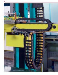
VARITRAK S -RMD<strong>steel</strong> <strong>tube</strong>Steel <strong>tube</strong> carrier systemcablecarriersystemKey Features:• Extremely durable stainless or plated <strong>steel</strong> side chain band material• Quick and easy cable installation• Available with made-to-order bored aluminum bars• Vertical and horizontal cable separation in nylon or aluminumavailable• Mounting brackets allow for surface or face connection options• Totally enclosed metallic <strong>tube</strong> provides optimal protection fromred-hot chips• Never worry about red-hot chips again20.01
GENERAL DATATotal Machine Travel (L S )VARITRAK S RMD20EVA9CONOMICALUEDDEDA product group’s EVA score is a general indicatorthat allows a customer to quickly and easilycompare a product group’s basic price, features,capabilities and value relative to other comparablysized products within the KS product range.Download 3D CAD files, videos,updated product info & much more at:www.kabelschlepp.com/varitraksrmd.htmDimensions ininches (mm)Technical DataSeriesS 0650.1Option AOption BOption COption DMounting!*HeightH11.02(280)12.60(320)14.17(360)17.72(450)BendRadiusKR *4.53(115)5.31(135)6.10(155)7.87(200)RetractedHDepotU B10.63(270)11.42(290)12.20(310)13.98(355)L BLoopLengthL B24.45(621)26.93(684)29.41(747)34.96(888)Bend Radius (KR) tolerance is +5% / -10%** Bending radii 125 mm, 145 mm, 175 mm, 250 mm, 300 mm and400 mm available via special order. Consult factory for more information.KRU BC LAdditional LoadFixedEndExtendedMovingEndt = Link Pitch0650 2.56 (65)Self-Supporting Lengthslbsft20.213.46.7kgm302010Calculation of Chain LengthL S= total machine travelL B= 3.14 x KR + (4 x t safety factor)L K= chain length requiredL K= LS ÷ 2 + length of the curve (L B)** Assumes the Fixed Point is located at theCenter of the Total Machine Travel.S 0650.1How To Order1-800-443-4216major creditcards accepted00 1 233.3 6.6 9.8Extended Travel:When application travelexceeds the self-supportinglength of VARITRAK S carriersystems, KS Support Rollers orRolling Carriage Systems canbe used to extend travel.Unsupported LengthmftFor more information onextended travel systems,see pages 2.27-2.36Number ofSystems Req.xCarrierType+Cavity Width(Bi )+TypeFrame Stay+BendRadiusx# of LinksLength+Type & PositionBrackets+Dividers(#vert / #horz)6xS0650.1-18.00”-RMD-135x32 Links+MAI/FAI+5v/0h20.02Specifications are subject to change without notice.KSA-0810-GC
A member of the TSUBAKI GROUPVARITRAK S RMD<strong>steel</strong> & aluminum • <strong>tube</strong> style • customizable widthsSeries S 0650.1RMDFeatures rugged bolted-on aluminum lids on the inner and outer radius.Usable Cavity Widths (Bi) available from 2.00” (50.8 mm) through18.00” (457.2 mm) in any width increment required by the customer.Lid SystemS0650.1 - 2.00” - RMD - (KR) - (# of links) - (brackets) - (dividers)B st = Cut lid widthStandardRMD STYLEB k = Outer chain widthVertical DividerBPN: 44252i = Inner chain cavity(usable) widthRecommendeddividers can beslid into position hMINIMUM 1.97G = Outer chain link heighthG = (50)Bi = 2.001.18(50.8)(30)Width= h ih i = Inner chain cavity0.12(3) =sT(usable) heightST = Vertical dividerthickness2.71 Bst =Bst = Bi + 0.71 (18)(68.8)3.50Bk = (88.8)Bk = Bi + 1.50 (38)S0650.1 - 18.00” - RMD - (KR) - (# of links) - (brackets) - (dividers)bolt-on aluminum lidson outside radiusVARITRAK S RMD20RecommendedMAXIMUMWidth1.97hG = (50)MaximumCable O.D.= h i x 0.9MaximumHose O.D.= h i x 0.8Bi = 18.00(457.2)1.18(30) = h iNote: For extended widths,multiple chain-band designsare available, please consultfactory: 1-800-443-421618.71 Bst =(475.2)19.50Bk = (495.2)bolt-on aluminum lidson inside radiusWhy use RMD systemRMD System Assembly Detail• Completely enclosed cavity design providesexcellent protection from hot chips and debris.• Aluminum lids and <strong>steel</strong> side-bands are highlyheat resistant.• Robust <strong>steel</strong> chain design offers maximumstrength and unsupported lengths for a <strong>tube</strong> stylecarrier.Anschluß• Available in widths customized to the exactdimension to fit any application’s widthrestrictions.• Lids can be removed from either the insideor outside radius to allow easy access forinstallation, maintenance and servicing of cablesand hoses.Mounting Bracket OptionsFor detailed drawings anddimensions of available options,please see page: 20.10Specifications are subject to change without notice.KSA-0810-GCNeed help? 1-800-443-4216 or www.kabelschlepp.com 20.03
GENERAL DATATotal Machine Travel (L S )VARITRAK S RMD20EVA9CONOMICALUEDDEDA product group’s EVA score is a general indicatorthat allows a customer to quickly and easilycompare a product group’s basic price, features,capabilities and value relative to other comparablysized products within the KS product range.Download 3D CAD files, videos,updated product info & much more at:www.kabelschlepp.com/varitraksrmd.htmDimensions ininches (mm)TechnicalTechnicalDatadataSeriesS 0950Option AOption BOption COption DOption EMounting!*HeightH16.06(408)18.43(468)23.15(588)25.51(648)27.87(708)BendRadiusKR6.69(170)7.87(200)10.24(260)11.42(290)12.60(320)*RetractedHDepotU B15.55(395)16.73(425)19.09(485)20.28(515)21.46(545)L BLoopKRLengthL B35.98(914)39.69(1008)47.13(1197)50.83(1291)54.53(1385)Bend Radius (KR) tolerance is +5% / -10%** Bending radii 350 mm & 410 mm are available via special order.Consult factory for more information.U BC LAdditional Loadlbsft26.920.213.46.7FixedEndExtendedMovingEndt = Link Pitch0950 3.74 (95)Self-Supporting Lengthskgm40302010Calculation of Chain LengthL S= total machine travelL B= 3.14 x KR + (4 x t safety factor)L K= chain length requiredL K= LS ÷ 2 + length of the curve (L B)** Assumes the Fixed Point is located at theCenter of the Total Machine Travel.S 0950How To Order1-800-443-4216major creditcards accepted00 1 2 3 4 5 m3.3 6.6 9.8 13.1 16.4 ftExtended Travel:When application travelexceeds the self-supportinglength of VARITRAK S carriersystems, KS Support Rollers orRolling Carriage Systems canbe used to extend travel.Unsupported LengthFor more information onextended travel systems,see pages 2.27-2.36Number ofSystems Req.xCarrierType+Cavity Width(Bi )+TypeFrame Stay+BendRadiusx# of LinksLength+Type & PositionBrackets+Dividers(#vert / #horz)10xS0950-15.00”-RMD-170x40 Links+MAI/FAI+5v/0h20.04Specifications are subject to change without notice.KSA-0810-GC
A member of the TSUBAKI GROUPVARITRAK S RMD<strong>steel</strong> & aluminum • <strong>tube</strong> style • customizable widthsSeries S 0950RMDFeatures rugged bolted-on aluminum lids on the inner and outer radius.Usable Cavity Widths (Bi) are available from 3.00” (76.2 mm) through23.00” (584.2 mm) in any width increment required by the customer.Lid SystemStandardS0950 - 3.00” - RMD - (KR) - (# of links) - (brackets) - (dividers)RMD STYLEB st = Cut lid widthVertical DividerB k = Outer chain widthPN: 42130Bdividers can bei = Inner chain cavityRecommendedslid into position(usable) width2.68MINIMUM hG = (68)Bi = 3.001.73h(76.2)(44) = hiG = Outer chain link heightWidth0.16h(4) =sTi = Inner chain cavity(usable) heightST = Vertical dividerthickness3.71 B st =B(94.2)st = B i + 0.71 (18)4.69B k = (119.2)B k = B i + 1.69 (43)S0950 - 23.00” - RMD - (KR) - (# of links) - (brackets) - (dividers)bolt-on aluminum lidson outside radiusVARITRAK S RMD20RecommendedMAXIMUMWidthh G = 2.68(68)23.00MaximumBCable O.D.i = (584.2)= h i x 0.9MaximumHose O.D.= h i x 0.81.73(44) = h iNote: For extended widths,multiple chain-band designsare available, please consultfactory: 1-800-443-4216B st =23.71(602.2)24.69B k = (627.2)bolt-on aluminum lidson inside radiusWhy use RMD systemRMD System Assembly Detail• Completely enclosed cavity design providesexcellent protection from hot chips and debris.• Aluminum lids and <strong>steel</strong> side-bands are highlyheat resistant.• Robust <strong>steel</strong> chain design offers maximumstrength and unsupported lengths for a <strong>tube</strong> stylecarrier.Anschluß• Available in widths customized to the exactdimension to fit any application’s widthrestrictions.• Lids can be removed from either the insideor outside radius to allow easy access forinstallation, maintenance and servicing of cablesand hoses.Mounting Bracket OptionsFor detailed drawings anddimensions of available options,please see pages: 20.10 - 20.11Specifications are subject to change without notice.KSA-0810-GCNeed help? 1-800-443-4216 or www.kabelschlepp.com 20.05
VARITRAK S RMD20GENERAL DATAEVA9CONOMICALUEDDEDA product group’s EVA score is a general indicatorthat allows a customer to quickly and easilycompare a product group’s basic price, features,capabilities and value relative to other comparablysized products within the KS product range.Download 3D CAD files, videos,updated product info & much more at:www.kabelschlepp.com/varitraksrmd.htmDimensions ininches (mm)Technical DataRetractedHTotal Machine Travel (L S )L BKRU BC LExtendedFixedEndMovingEndt = Link Pitch1250 4.92 (125)Calculation of Chain LengthL S= total machine travelL B= 3.14 x KR + (4 x t safety factor)L K= chain length requiredL K= LS ÷ 2 + length of the curve (L B)** Assumes the Fixed Point is located at theCenter of the Total Machine Travel.SeriesS 1250Option AOption BOption COption DOption EOption FOption GMountingHeightH24.17(614)27.32(694)30.47(774)33.62(854)39.92(1014)43.07(1094)50.94(1294)How To Order1-800-443-4216Number ofSystems Req.x!*CarrierTypeBendRadiusKR*10.24(260)11.81(300)13.39(340)14.96(380)18.11(460)19.69(500)23.62(600)major creditcards acceptedDepotU B21.93(557)23.50(597)25.08(637)26.65(677)29.80(757)31.38(797)35.31(897)LoopLengthL B51.85(1317)56.77(1442)61.73(1568)66.69(1694)76.57(1945)81.54(2071)93.90(2385)Bend Radius (KR) tolerance is +5% / -10%** Bending radii 420 mm, 540 mm & 1000 mm are available via specialorder. Consult factory for more information.+Cavity Width(Bi )+TypeFrame Stay+BendRadiusxAdditional LoadSelf-Supporting Lengthslbs kgft m33.6 5026.9 4020.2 3013.4 206.71000 1 2 3 4 5 6 m3.3 6.6 9.8 13.1 16.4 19.7 ftExtended Travel:When application travelexceeds the self-supportinglength of VARITRAK S carriersystems, KS Support Rollers orRolling Carriage Systems canbe used to extend travel.# of LinksLength+S 1250Unsupported LengthFor more information onextended travel systems,see pages 2.27-2.36Type & PositionBrackets+Dividers(#vert / #horz)12xS1250-28.25”-RMD-260x42 Links+MIA/FIA+14v/3h20.06Specifications are subject to change without notice.KSA-0810-GC
RecommendedMINIMUMWidthA member of the TSUBAKI GROUPVARITRAK S RMD<strong>steel</strong> & aluminum • <strong>tube</strong> style • customizable widthsSeries S 1250RMDFeatures rugged bolted-on aluminum lids on the inner and outer radius.Usable Cavity Widths (Bi) are available from 4.00” (101.6 mm) through30.00” (762 mm) in any width increment required by the customer.Lid SystemBS1250 - 4.00” - RMD - (KR) - (# of links) - (brackets) - (dividers)Standardst = Cut lid widthRMD STYLEBVertical Dividerk = Outer chain widthPN: 42880B i = Inner chain cavitydividers can be(usable) widthslid into positionh3.70 hG = (94)Bi = 4.002.72G = Outer chain link height(101.6)(69) = hih0.20i = Inner chain cavity=s(5) T(usable) heightST = Vertical dividerthickness4.98B st =B(126.6)st = B i + 0.98 (25)6.24B k = (158.6)B k = B i + 2.24 (57)S1250 - 30.00” - RMD - (KR) - (# of links) - (brackets) - (dividers)bolt-on aluminum lidson outside radiusVARITRAK S RMD20RecommendedMAXIMUMWidthh G = 3.70(94)Maximum30.00BCable O.D.i = (762)= h i x 0.9MaximumHose O.D.= h i x 0.82.72(69) = h iNote: For extended widths,multiple chain-band designsare available, please consultfactory: 1-800-443-4216B st =B k =30.98(787)32.24(819)bolt-on aluminum lidson inside radiusWhy use RMD systemRMD System Assembly Detail• Completely enclosed cavity design providesexcellent protection from hot chips and debris.• Aluminum lids and <strong>steel</strong> side-bands are highlyheat resistant.• Robust <strong>steel</strong> chain design offers maximumstrength and unsupported lengths for a <strong>tube</strong> stylecarrier.Anschluß• Available in widths customized to the exactdimension to fit any application’s widthrestrictions.• Lids can be removed from either the insideor outside radius to allow easy access forinstallation, maintenance and servicing of cablesand hoses.Mounting Bracket OptionsFor detailed drawings anddimensions of available options,please see pages: 20.10 - 20.11Specifications are subject to change without notice.KSA-0810-GCNeed help? 1-800-443-4216 or www.kabelschlepp.com 20.07
GENERAL DATATotal Machine Travel (L S )VARITRAK S RMD20EVA9CONOMICALUEDDEDA product group’s EVA score is a general indicatorthat allows a customer to quickly and easilycompare a product group’s basic price, features,capabilities and value relative to other comparablysized products within the KS product range.Download 3D CAD files, videos,updated product info & much more at:www.kabelschlepp.com/varitraksrmd.htmDimensions ininches (mm)Technical DataSeriesS 1800Option AOption BOption COption DOption EMounting!*HeightH30.71(780)35.04(890)39.76(1010)44.09(1120)53.15(1350)BendRadiusKR *12.60(320)14.76(375)17.13(435)19.29(490)23.82(605)RetractedHL BDepotU B29.53(750)31.69(805)34.06(865)36.22(920)40.75(1035)KRU BLoopLengthL B67.91(1725)74.72(1898)82.17(2087)88.94(2259)103.15(2620)Bend Radius (KR) tolerance is +5% / -10%** Bending radii 720 mm, 890 mm, 1175 mm & 1405 mm are available viaspecial order. Consult factory for more information.C LFixedEndAdditional LoadExtendedMovingEndt = Link Pitch1800 7.09 (180)Self-Supporting Lengthslbs kgft m40.3 6033.6 5026.9 4020.2 3013.4 20Calculation of Chain LengthL S= total machine travelL B= 3.14 x KR + (4 x t safety factor)L K= chain length requiredL K= LS ÷ 2 + length of the curve (L B)** Assumes the Fixed Point is located at theCenter of the Total Machine Travel.S 18006.710How To Order1-800-443-4216Number ofSystems Req.xCarrierType+Cavity Width(Bi )major creditcards accepted+TypeFrame Stay+BendRadiusx00 1 2 3 4 5 6 7 8 9 m3.3 6.6 9.8 13.1 16.4 19.7 23 26.2 29.5 ftExtended Travel:When application travelexceeds the self-supportinglength of VARITRAK S carriersystems, KS Support Rollers orRolling Carriage Systems canbe used to extend travel.# of LinksLength+Unsupported LengthFor more information onextended travel systems,see pages 2.27-2.36Type & PositionBrackets+Dividers(#vert / #horz)10xS1800-20.00”-RMD-435x35 Links+MIA/FAA+5v/0h20.08Specifications are subject to change without notice.KSA-0810-GC
RMDLid SystemS1800 - 6.00” - RMDRecommendedMINIMUMWidth5.51 hG = (140)Bi = 6.00(152.4)7.30Bst = (185.4)4.09(104) = hiBst = Bi + 1.30 (33)A member of the TSUBAKI GROUPVARITRAK S RMD<strong>steel</strong> & aluminum • <strong>tube</strong> style • customizable widthsFeatures rugged bolted-on aluminum lids on the inner and outer radius.Usable Cavity Widths (Bi) are available from 6.00” (152.4 mm) through37.00” (939.8 mm) in any width increment required by the customer.- (KR) - (# of links) - (brackets) - (dividers)StandardRMD STYLEVertical DividerPN: 43810dividers can beslid into position0.30(7.5) =s TSeries S 1800B st = Cut lid widthB k = Outer chain widthB i = Inner chain cavity(usable) widthh G = Outer chain link heighth i = Inner chain cavity(usable) heightST = Vertical dividerthicknessVARITRAK S RMD208.76Bk = (222.4)Bk = Bi + 2.76 (70)S1800 - 37.00” - RMD - (KR) - (# of links) - (brackets) - (dividers)bolt-on aluminum lidson outside radiusRecommendedMAXIMUMWidthhG = 5.51(140)Maximum37.00Cable O.D.Bi = (939.8)= h i x 0.9MaximumHose O.D.= h i x 0.84.09(104) = hiNote: For extended widths,multiple chain-band designsare available, please consultfactory: 1-800-443-4216Bst =38.30(972.8)39.76Bk = (1009.8)bolt-on aluminum lidson inside radiusWhy use RMD systemRMD System Assembly Detail• Completely enclosed cavity design providesexcellent protection from hot chips and debris.• Aluminum lids and <strong>steel</strong> side-bands are highlyheat resistant.• Robust <strong>steel</strong> chain design offers maximumstrength and unsupported lengths for a <strong>tube</strong> stylecarrier.Anschluß• Available in widths customized to the exactdimension to fit any application’s widthrestrictions.• Lids can be removed from either the insideor outside radius to allow easy access forinstallation, maintenance and servicing of cablesand hoses.Mounting Bracket OptionsFor detailed drawings anddimensions of available options,please see pages: 20.10 - 20.11Specifications are subject to change without notice.KSA-0810-GCNeed help? 1-800-443-4216 or www.kabelschlepp.com 20.09
VARITRAK S Series Standard Mounting BracketsVARITRAK S RMDFIXED ENDkijMOVING ENDvtu20gcdbafehrqn o pmlsStandard Mount - Fixed End BracketsSize a b c d e f g h i j kS 0650 B k + 0.98 (25) B k – 1.45 (37) 0.68 (17) 0.51 (13) 1.18 (30) 0.12 (3) 0.20 (5) 0.59 (15) 1.77 (45) 3.74 (95) 0.25 (6.4)S 0950 B k + 1.93 (49) B k – 2.48 (63) 1.18 (30) 0.98 (25) 2.16 (55) 0.15 (4) 0.39 (10) 0.79 (20) 2.55 (65) 4.91 (125) 0.33 (8.4)S 1250 B k + 1.81 (46) B k – 2.52 (64) 1.18 (30) 0.98 (25) 2.16 (55) 0.19 (5) 0.39 (10) 0.98 (25) 3.14 (80) 6.09 (155) 0.41 (10.5)S 1800 B k + 2.08 (53) B k – 3.03 (77) 1.38 (35) 0.98 (25) 2.36 (60) 0.19 (5) 0.39 (10) 1.18 (30) 4.52 (115) 8.25 (210) 0.51 (13)Standard Mount - Moving End BracketsSize l m n o p q r s t u vS 0650 B k + 0.75 (19) B k – 1.69 (43) 0.68 (17) 0.51 (13) 1.18 (30) 0.12 (3) 0.20 (5) 0.59 (15) 1.77 (45) 3.74 (95) 0.25 (6.4)S 0950 B k + 1.61 (41) B k – 2.79 (71) 1.18 (30) 0.98 (25) 2.16 (55) 0.16 (4) 0.39 (10) 0.79 (20) 2.55 (65) 4.91 (125) 0.33 (8.4)S 1250 B k + 1.41 (36) B k – 2.91 (74) 1.18 (30) 0.98 (25) 2.16 (55) 0.20 (5) 0.39 (10) 0.98 (25) 3.14 (80) 6.09 (155) 0.41 (10.5)S 1800 B k + 1.61 (41) B k – 3.46 (88) 1.38 (35) 0.98 (25) 2.36 (60) 0.20 (5) 0.39 (10) 1.18 (30) 4.52 (115) 8.25 (210) 0.51 (13)VARITRAK S Standard BracketPosition OptionsBracket EndM - Moving EndF - Fixed EndBracket PositionA - connecting surface onoutside radius (standard)I - connecting surface oninside radiusH - connecting surface turned 90°to the outside radiusK - connecting surface turned 90°to the inside radiusU - Universal Bracket(not pictured, see opposite page)Please specify the desired bracket variant and position when orderingExample: FAI/MAI (Standard) or FAA/MIAFKFHFIM HM KFA (Standard)The bracket positions at the Fixed End and Moving End can be changed later if required.M A (Standard)M IAI (Standard)I (Standard)Bracket feet on the standard brackets canbe positioned facing inward (I) which is thestandard position or facing outward (A)A20.10Specifications are subject to change without notice.KSA-0810-GC
Fixed EndFixed EndMoving EndMoving EndA member of the TSUBAKI GROUPVARITRAK S RMD<strong>steel</strong> & aluminum • <strong>tube</strong> style • customizable widthsVARITRAK S Series Face Mount BracketsFIXED ENDjjtop viewvMOVING ENDvtop viewVARITRAK S RMDfeferqrq20FIXED ENDfront viewdkdkMOVING ENDpfront viewwpwliclicxuoxuohhttggssbbnnaammFace Mount - Male End BracketsSize a b c d e f g h i j k lS 0950 B i + 4.84 (122.9) B i + 3.09 (78.5) - 0.88 (22.4) 1.75 (44.5) 0.16 (4) 0.75 (19.1) 0.50 (12.7) 3.00 (88.9) 3.50 (88.9) 0.41 (10.4) 4.00 (101.6)S 1250 B i + 5.27 (133.9) B i + 3.52 (89.4) - 0.88 (22.4) 1.75 (44.5) 0.18 (4.6) 0.75 (19.1) 0.50 (12.7) 3.00 (88.9) 3.50 (88.9) 0.41 (10.5) 4.00 (101.6)S 1800 B i + 7.39 (187.7) B i + 4.78 (124.4) 2.00 (50.8) 1.31 (33.3) 2.63 (66.8) 0.20 (5.1) 1.00 (25.4) 1.26 (32) 3.00 (88.9) 4.50 (114.3) 0.56 (14.2) 5.51 (140)Face Mount - Female End BracketsSize a b c d e f g h i j k lS 0950 B i + 4.52 (114.8) B i + 2.77 (70.4) - 0.88 (22.4) 1.75 (44.5) 0.16 (4) 0.75 (19.1) 0.50 (12.7) 3.00 (88.9) 3.50 (88.9) 0.41 (10.4) 4.00 (101.6)S 1250 B i + 4.88 (124) B i + 3.13 (79.5) - 0.88 (22.4) 1.75 (44.5) 0.18 (4.6) 0.75 (19.1) 0.50 (12.7) 3.00 (88.9) 3.50 (88.9) 0.41 (10.5) 4.00 (101.6)S 1800 B i + 6.92 (175.8) B i + 4.29 (109) 2.00 (50.8) 1.31 (33.3) 2.63 (66.8) 0.20 (5.1) 1.00 (25.4) 1.26 (32) 3.00 (88.9) 4.50 (114.3) 0.56 (14.2) 5.51 (140)VARITRAK SFace Mount BracketBracket EndM - Moving EndF - Fixed EndBracket DesignationF - Face Mount Bracket (standard position)When specifying VARITRAK S Face Mount Brackets, use the letter F for the Bracket Position designation of the assembly part number description.Example: FF/MFSpecifications are subject to change without notice.KSA-0810-GCNeed help? 1-800-443-4216 or www.kabelschlepp.com 20.11
A member of the TSUBAKI GROUPPhone: 414-354-1994Fax: 414-354-1900www.kabelschlepp.comsales@kabelschlepp.comKabelSchlepp America, Inc.7100 W. Marcia Road, Milwaukee, WI 53223 - USA


