Create successful ePaper yourself
Turn your PDF publications into a flip-book with our unique Google optimized e-Paper software.
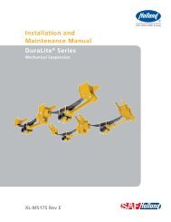
AD SERIESMAINTENANCEAND PARTS LISTAD SeriesHeavy-Duty Drive Axle Air SuspensionMaintenance and Parts List Manual<strong>XL</strong>-<strong>AK398</strong>-<strong>01</strong> <strong>Rev</strong>. D
CONTENTSPagePageIntroduction .................................................................................2Warranty .......................................................................................2Notes, Cautions, and Warnings .....................................................2Model Identification .....................................................................3Model Nomenclature ...................................................................3Operating and Maintenance Instructions ....................................4Pre-operational Checklist .............................................................5Parts List – AD-123/246/369 Series ..............................................6Parts List – AD-126/252/378 Series ..............................................7Parts List – AD-130/260/390 Series ..............................................8Equalizing Beam Model Identification ..........................................9Height Control Valve Adjustment ...............................................10Service Repair Kits ..............................................................10 - 12Replacement Instructions ...................................................13 - 16AD Series Suspension Torque andLubrication Identification ...................................................17Troubleshooting ..................................................................18 - 19Contact Information....................................................................20INTRODUCTIONThis manual provides you information necessary for thecare, maintenance, inspection, and safe operation of <strong>Holland</strong>Neway’s AD Series drive axle air suspension models.The <strong>Holland</strong> Neway Air Suspension is designed and engineeredto provide trouble-free service. In the event of minor breakdown,such as a loss of air in the air springs, there are safety featuresdesigned into the suspension that will allow the vehicle to bedriven CAUTIOUSLY at slow speed, to the nearest service facility.This suspension uses air delivered from the truck/tractor airsystem to pressurize the air springs.The height controlvalve regulates the air pressure required for varying loads andmaintains the design ride height.This suspension can providea cushioned ride throughout the load range, from empty tofully loaded.WARRANTYRefer to the complete warranty for the country in which theproduct will be used.A copy of the written warranty is includedwith the product as well as in the suspension catalogs and theSAF-HOLLAND <strong>Group</strong> Web Site (www.safholland.us)It may also be ordered directly from the address shown on theback cover.NOTES, CAUTIONS,AND WARNINGSYou must read and understand all of the safety procedurespresented in this manual before starting any work onthe suspension.Proper tools must be used to perform the maintenance andrepair procedures described in this manual. Many of theseprocedures require special tools.Failure to use the proper equipment could result in personalinjury and/or damage to the suspension.Safety glasses must be worn at all times whenperforming the procedures covered in this manual.Throughout this manual, you will notice the terms “NOTE,”“IMPORTANT,”“CAUTION” and “WARNING” followed byimportant product information. So that you may betterunderstand the manual, those terms are as follows:NOTE:<strong>Inc</strong>ludes additional information toenable accurate and easy performanceof procedures.IMPORTANT: <strong>Inc</strong>ludes additional information thatif not followed could lead to hinderedproduct performance.Used without the safety alert symbol,indicates a potentially hazardous situationwhich, if not avoided, may result inproperty damage.Indicates a potentially hazardous situationwhich, if not avoided, may result in minoror moderate injury.Indicates a potentially hazardous situationwhich, if not avoided, could result in deathor serious injury.2<strong>XL</strong>-<strong>AK398</strong>-<strong>01</strong> <strong>Rev</strong>. D
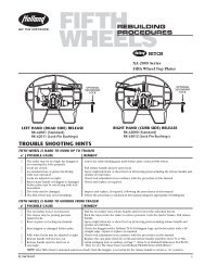
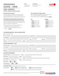
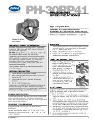
MODEL IDENTIFICATIONA serial number tag is attached to the underside of thetransverse beam air spring mounting plate for identificationpurposes.This tag supplies valuable information regarding theexact components used to manufacture the suspension.FIGURE 1Installed AD Series SuspensionMODEL NOMENCLATUREAIR DRIVENO. OF A<strong>XL</strong>ES1 - SINGLE2 - TANDEM3 - TRIDEMRATED CAPACITY(X 1,000 LBS.)AD - 2 46 - 10RIDE HEIGHT (INCHES)IMPORTANT: This manual applies to the suspensionmodels or series listed below and forspecial orders of the same. It is veryimportant to determine your specificmodel number, serial number, and partslist number. Record those numbers on thispage, and refer to them when obtaininginformation or replacement parts.Serial Number Tag location(underside of plate)Depending upon chassis builder configuration, the serial numbertag may not call out the exact kit or parts list number. If so, thevehicle chassis builder should be able to identify the suspensionmodel and its components using the vehicle's VIN number.Page 9 of this manual supplies a dimensional view of the variousAD Series equalizing beams to aid in identifying equalizingbeams to a particular series (i.e.,AD-123,AD-126,AD-130).IMPORTANT: Due to the custom built nature of each ADapplication, having the exact parts list usedby the chassis builder is critical in determiningproper replacement components.It is recommended that you determine your specific modelnumber, write that information below, and refer to it whenobtaining information or replacement parts.Model Number _______________________________Serial Number ________________________________Parts List Number_____________________________Single Axle:AD-123 AD-124*AD-126 AD-127*AD-130 AD-132*Tandem Axle:AD-246 AD-248*AD-252 AD-254*AD-260 AD-264*Tridem Axle:AD-369AD-378AD-390* Denotes special uprating for fire apparatus applications onlywith SAF-HOLLAND Engineering approvals.FIGURE 2Serial Number TagHOLLAND USA, INC.MANUFACTURED UNDER ONE OR MORE OF THE FOLLOWING U.S. PATENTS:5,639,110 5,588,665 4,595,216 4,615,539 5,354,0915,393,096 5,088,763 5,083,812 5,203,585 5,470,0965,2<strong>01</strong>,898 5,288,100 6,241,266 5,924,712 4,838,5786,073,946 6,062,578 6,116,626 6,328,322 4,838,5666,398,236 4,871,188MODEL NO.AD-246-10CAPACITY (LBS)46,000PART NO.SERIAL NO.33000356A3-09532-YZCONSULT SPECIFICATION FOR CAPACITY AND RECOMMENDED APPLICATION.PART NO. 938 00 269In Service Date _______________________________<strong>XL</strong>-<strong>AK398</strong>-<strong>01</strong> <strong>Rev</strong>. D3
OPERATING AND MAINTENANCE INSTRUCTIONSIn typical straight truck applications, the AD Series Suspensionis controlled by dual height control valves.In typical tractor applications, the AD Series suspension maybe controlled by either a single or dual height control valve.Buses and motor homes,depending on chassis builderspecification, may use either single or dual height control valve.When properly adjusted, the height control valve(s) willautomatically maintain the desired ride height throughout theunloaded to loaded range.The height control valve automaticallyadds air to (or exhaust air from) the air suspension, to maintaina constant ride height.Before putting the vehicle in operation, build air pressure inexcess of 70 P.S.I.G.This will open the pressure protectionvalve, and allow air flow to the height control valves.IMPORTANT:ROUTINE MAINTENANCE AND DAILY INSPECTIONDaily InspectionDaily or before each trip, check the suspension to be sure it isfully operational and visually free of any obvious signs offailure in any major component.Visually inspect air springs forsufficient and equal pressure and to see that suspension is setat proper ride height. See page 10 for ride height measurementand re-setting instructions. Service as necessary.Initial 5,000 Mile (8,000 KM) or 100 Hoursof Service Inspection1. Suspension ride height (underside of frame to centerlineof axle) MUST BE WITHIN ±1/4˝ OF RECOMMENDEDDESIGN HEIGHT. See page 10 for instructions onmeasuring ride height.An improperly set ride height couldresult in suspension componentdamage and/or poor vehicle ride performance.2. After initial 5,000 miles (8,000 KM) or 100 hours ofservice, inspect bolts and nuts at the pivot connections,transverse beam connections, and axle connections toassure they are properly torqued. Check all other nuts andbolts for proper torque. Re-torque as necessary thereafter.3. With vehicle on level surface and air pressure in excessof 70 P.S.I.G., all air springs should be of sufficient andequal firmness.Routine Maintenance – 50,000 Miles (80,000 KM)or 1,000 Hours of Service or as NeededAt 50,000 miles or 1,000 hours of service, or whenservicing vehicle brake system, inspect suspensioncomponents per 5,000 mile inspection.Also check allother suspension components for any sign of damage,looseness, wear or cracks. Replace any damaged partsto prevent equipment breakdown.TORQUE CHARTTORQUEIN FT. LBS.SIZE ITEM AD MODELS NM1/2˝ and 3/4˝ Air Spring 30-35 40-471 1 /8˝ Pivot 600 8131 1 /4˝ Pivot (AD-130 only) 700 9493/4˝ Shock Absorber 150 2032 1 /4˝ Transverse Beam 500-1000 677-13561˝-8x6˝ Bar Pin Bolt 680 9223/4˝-10x7-1/2˝ Thru Bolt 135 183TORQUE NOTE:Torque specifications are with clean threads.IMPORTANT:Use of special lubricants with friction modifiers, such asAnti-Seize or Never-Seize, without written approval from<strong>Holland</strong> Engineering, will void warranty and could lead tobolt failure or other component issues.TRANSVERSE BEAM:AD Models: Torque to specification, then bend the tab washerover the heavy hex nut. Use a hammer to pound the tabagainst a flat or edge of the nut.NOTE:Height control valves control all air springs.Check all fittings for air leaks, by applyinga soapy water solution and checking forbubbles at all air connections and fittings.4 <strong>XL</strong>-<strong>AK398</strong>-<strong>01</strong> <strong>Rev</strong>. D
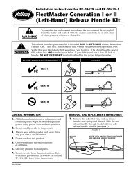
PRE-OPERATIONAL CHECKLISTFIGURE 3AD-123/126 Models10AD-123/126 Models5111662AD-130 Model571391514 84 3Prior to placing unit in service, check the following items:1. Build the vehicle’s air pressure above 70 P.S.I.G.With thevehicle shut off, check the system for air leaks.2. Minimum clearance around air springs must be 1 1 /2˝when fully laden, 2.0˝ when unladen.3. Check the shock absorbers for proper installation.4. 3/4˝ Shock absorber hardware must be torqued to thespecifications found in the Torque Chart on page 4.5. 1/2˝ and 3/4˝ Air spring mounting hardware must betorqued to the specifications found in the Torque Chart onpage 4.6. A 1 1 /8˝ pivot nut (1 1 /4˝ pivot nut for AD-130 Series) mustbe torqued to the specifications found in the Torque Charton page 4.NOTE: As of June 2002, all pivot bolts supplied bySAF-HOLLAND will have a pre-applied coating(silver in color) that will provide threadlubrication throughout the expected service life ofthe bolts. See page 17 for additional information.7. Check for proper installation of the spacer washers at thetransverse beam and pivot connection.FIGURE 4Spacer Washer Installation33 1 /2˝34˝FRAME WIDTH FRAME WIDTH71234 1 /2˝FRAME WIDTH516NOTE: Different frame widths require various spacerwasher placement at the ad-130 pivot rear iso line connection.8. Axle hanger bracket connection nuts must be torqued,see Torque Chart on page 4.9. The transverse beam connection nut (2 1 /4˝) must betorqued to the specifications found in the Torque Charton page 4. Bend the tab over after the nut is torqued.10. The lower flange of the frame bracket must be securelyattached by fasteners to the bottom of the crossmember.11. 3/4˝ Frame bracket mounting bolts must be torqued tochassis builder specifications. chassis builder-supplied spacersmust be used between the frame bracket and crossmember.12. With the vehicle on a level surface, and the air supplypressure in excess of 70 P.S.I.G., check all the air springsfor equal firmness.13. The suspension ride height should be within ± 1/4˝ ofthe recommended design height. See Height Control ValveAdjustment for the proper setting, page 10.14. Welds connecting the adapters to the axle mustbe per axle manufacturer’s specifications.15. The pinion angle should be within chassisbuilder specifications.16. Be sure that functional axle stops are present.The axlestop design should be adequate for the capacity andproper height; and should distribute the vertical forcessufficiently on the axle housing to prevent damage tothe vehicle frame and/or axle. Unless supplied bySAF-HOLLAND, the axle stop is the responsibility of thevehicle chassis builder.2 SPACERWASHERS INSIDE<strong>XL</strong>-<strong>AK398</strong>-<strong>01</strong> <strong>Rev</strong>. D1 SPACER WASHEREACH SIDE2 SPACERWASHERS OUTSIDE5
PARTS LIST – AD-123/246/369 SERIESIMPORTANT: AD Series Suspension components vary by assembly part number and OEM/Chassis builder specifications.To ensureproper part number identification before placing order, refer to OEM/Chassis builder's specifications or visually checkcomponent to be replaced for part number. If part number can not be identified or confirmed please contactSAF-HOLLAND technical service for assistance - 888-396-65<strong>01</strong>.BAR PIN STYLE A<strong>XL</strong>ECONNECTION517791226 45.75˝THROAT OPENING102642L2A12168182E252112C21222ETHRU BOLT STYLEA<strong>XL</strong>E CONNECTION2B11 23 24 2D2318242DA<strong>XL</strong>E GROUPINGSITEM #AD-123/246/369PART NO. DESCRIPTIONSINGLEQTY.TANDEMQTY.TRIDEMQTY.1 ** Air Spring with mounting bracket 2 4 62L ** Eq. Beam Assembly - Left Hand - Thru Bolt Design 1 2 32R ** Eq. Beam Assembly - Right Hand - Thru Bolt Design 1 2 32L ** Eq. Beam Assembly - Left Hand - Bar Pin Design 1 2 32R ** Eq. Beam Assembly - Right Hand - Bar Pin Design 1 2 32A 900 08 252 Rubber Bushing - Front Pivot 2 4 62B 900 08 008 Bushing - Beam Center - Thru Bolt style 2 4 62C 900 08 175 Bushing - Beam Center - Bar Pin style 2 4 62D 900 <strong>01</strong> 065 Washer for Thru Bolt style connection 4 8 122E 900 <strong>01</strong> 205 Washer for Bar Pin style connection 4 8 123 ** Transverse Beam Assembly 1 2 33A 900 08 219 Bushing - Transverse Beam 2 4 64 900 08 120**** Alignment Bushing (Qty. per adjustable bracket)** 2 4 65 ** Frame Bracket - LH adjustable (requires item 4) 1 2 3** Frame Bracket - RH fixed 1 2 36 936 00 498 Spacer Washer 2 4 67 ** Upper Shock Bracket 2 4 68 ** Shock Absorber 2 4 69 932 <strong>01</strong> 055 Hex Bolt 1-1/8˝ - 7 x 9.53˝ 2 4 610 934 00 506 Hex Nut 1-1/8˝ - 7 2 4 611 930 03 693 Hex Bolt 3/4˝ - 10 x 7-1/2˝ ( Thru Bolt Design only) 2 4 612 936 00 502 Washer - Pivot Spacer 4 8 1213 905 36 006 Locking Spacer Assembly 2 4 614 936 00 533 Lock Tab Washer 2 4 615 934 00 607 Heavy Hex Nut 2-1/4˝ - 8 2 4 616 930 03 615 Cap Screw 3/4˝ - 10 x 4.25˝ 2 4 617 930 03 591 Cap Screw 3/4˝ - 10 x 3.25˝ 2 4 618 934 00 492 Hex Nut 3/4˝ 2*** 4*** 6***19 934 00 136 Hex Nut 1/2˝ 2 4 620 936 00 072 Lock Washer 1/2˝ 2 4 621 936 00 168 Washer Flat Narrow 1˝ 8 16 2422 934 00 502 Hex Nut Lock 1˝-8 4 8 1223 936 00 156 Washer Flat Narrow (Thru) 3/4˝ 4 8 1224 900 <strong>01</strong> 002 Bushing Adapter (Thru) 4 8 1225 930 04 3<strong>01</strong> Cap Screw - 1˝ - 8 x 6˝ Gr. 8 (Bar Pin Only) 4 8 1226 936 00 174 Washer Flat Narrow 1.12˝ (Hardened) 4 8 12** Refer to the chassis builder specifications to properly identify the <strong>Holland</strong> part numbers for the components notedwith “ ** ”. A serial tag may be affixed to the transverse beam that also denotes the <strong>Holland</strong> kit number that willprovide the individual component numbers needed.*** The quantity shown is for a bar pin style unit. If a thru bolt style is used, increase the quantity by two per axle.**** Fabricated frame brackets may use a different alignment bushing. Part number shown is for cast hanger. Provide kit #from serial tag or frame bracket part number from OEM build (VIN) to SAF-HOLLAND service for applicable part number.6 <strong>XL</strong>-<strong>AK398</strong>-<strong>01</strong> <strong>Rev</strong>. D62<strong>01</strong>93A3131415
PARTS LIST – AD-126/252/378 SERIESIMPORTANT: AD Series Suspension components vary by assembly part number and OEM/Chassis builder specifications.To ensureproper part number identification before placing order, refer to OEM/Chassis builder's specifications or visually checkcomponent to be replaced for part number. If part number can not be identified or confirmed please contactSAF-HOLLAND technical service for assistance - 888-396-65<strong>01</strong>.THRU BOLT STYLEA<strong>XL</strong>E CONNECTION71927215.75˝THROAT OPENING9528 4122L410282A171216818202625121 2F112F2D2B2D1821BAR PIN STYLE A<strong>XL</strong>ECONNECTION222E2C2E2324A<strong>XL</strong>E GROUPINGSITEM #AD-126/252/378PART NO. DESCRIPTIONSINGLEQTY.TANDEMQTY.TRIDEMQTY.1 ** Air Spring 2 4 62L ** Eq. Beam Assembly - Left Hand - Thru Bolt Design(shown) 1 2 32R ** Eq. Beam Assembly - Right Hand - Thru Bolt Design 1 2 32L ** Eq. Beam Assembly - LH - Bar Pin Design (side view) 1 2 32R ** Eq. Beam Assembly - Right Hand - Bar Pin Design 1 2 32A 900 08 252 Bushing - Front Pivot 2 4 62B 900 08 195 Bushing - Beam Center - Thru Bolt style 2 4 62C 905 08 <strong>01</strong>2 Bushing - Beam Center - Bar Pin style 2 4 62D 900 36 210 Washer for Thru Bolt style connection (see inset diagram) 4 8 122E 936 00 168 Washer for Bar Pin style connection 8 16 242F 900 <strong>01</strong> 002 Adapter Bushing 4 8 123 ** Transverse Beam Assembly 1 2 33A 900 08 219 Bushing - Transverse Beam 2 4 64 900 08 120**** Alignment Bushing (qty. per Adj. bracket)** 2 4 65 ** Frame Bracket - LH adjustable (Shown) (Requires Item 4) 1 2 3** Frame Bracket - RH fixed 1 2 36 900 36 209 Washer 2 4 67 ** Upper Shock Bracket 2 4 68 ** Shock Absorber 2 4 69 932 <strong>01</strong> 055 Cap Screw 1.12˝ - 7 x 9.53˝ 2 4 610 934 00 506 Lock Nut 1.12˝ - 7 2 4 611 930 03 693 Cap Screw 3/4˝ - 10 x 7 1 /2˝ ( Thru Bolt Design only) 2 4 612 936 00 502 Washer - Pivot Spacer 4 8 1213 905 36 006 Locking Spacer Assembly 2 4 614 936 00 533 Tab Washer 2 4 615 934 00 607 Heavy Hex Nut 2 1 /4˝ - 8 2 4 616 930 03 615 Cap Screw 3/4˝ - 10 x 4.25˝ 2 4 617 930 03 591 Cap Screw 3/4˝ - 10 x 3.25˝ 2 4 618 934 00 492 Lock Nut 3/4˝ 2 *** 4 *** 6 ***19 934 00 136 Hex Nut 1/2˝ 2 4 620 936 00 072 Lock Washer 1/2˝ 6 12 1821 936 00 156 Washer Flat Narrow 0.75˝ 2 4 622 930 04 3<strong>01</strong> Bolt Hex 1˝ - 8x6˝ Gr 8 4 8 1223 934 00 502 Nut Hex Lock 1˝ - 8 4 8 1224 930 02 893 Bolt Hex 0.5˝ -13x1˝ Gr 2 4 8 1225 905 31 0<strong>01</strong> Air Spring Mounting Plate 2 4 626 900 23 131 Brace 2 4 627 934 00 417 Nut Hex Lock Thin .75˝ -16 Gr A 2 4 628 936 00 174 Washer Flat Narrow 1.12˝ (Hardened) 4 8 12** Refer to the chassis builder specifications to properly identify the <strong>Holland</strong> part numbers for the components notedwith “ ** ”. A serial tag maybe affixed to the transverse beam that also denotes the <strong>Holland</strong> kit number that will providethe individual component numbers needed. *** The quantity shown is for a bar pin style unit. If a thru bolt style is used, increase the quantity by two per axle.62033A13142D** 6˝ INTERNAL WIDTHA<strong>XL</strong>E MOUNTINGBRACKETS USEPN 900 36 244152D***** Fabricated frame brackets may use a different alignment bushing. Part number shown is for cast hanger. Provide kit #from serial tag or frame bracket part number from OEM build (VIN) to SAF-HOLLAND service for applicable part number.<strong>XL</strong>-<strong>AK398</strong>-<strong>01</strong> <strong>Rev</strong>. D7
PARTS LIST – AD-130/260/390 SERIESIMPORTANT: AD Series Suspension components vary by assembly part number and OEM/Chassis builder specifications.To ensureproper part number identification before placing order, refer to OEM/Chassis builder's specifications or visually checkcomponent to be replaced for part number. If part number can not be identified or confirmed please contactSAF-HOLLAND technical service for assistance - 888-396-65<strong>01</strong>.23751042A12818192220 282126412161892L1THRU BOLT STYLEA<strong>XL</strong>E CONNECTION251811252F2B2FFOR 12˝ OR ABOVE RIDEHEIGHT MODELS ONLY27246202<strong>01</strong>73A3131415A<strong>XL</strong>E GROUPINGSITEM #AD-130/260/390PART NO. DESCRIPTIONSINGLEQTY.TANDEMQTY.TRIDEMQTY.1 ** Air Spring with mounting bracket 2 4 62L ** Eq. Beam Assembly - Left Hand - Thru Bolt Design (shown) 1 2 32R ** Eq. Beam Assembly - Right Hand - Thru Bolt Design 1 2 32A 900 08 256 Bushing - Front Pivot 2 4 62B 900 08 225 Bushing - Beam Center - Thru Bolt style 2 4 62F 900 <strong>01</strong> 349 Adapter Bushing 4 8 123 ** Transverse Beam Assembly 1 2 33A 900 08 135 Bushing - Transverse Beam 2 4 64 900 08 232 Alignment Bushing (qty. per Adj. Bracket) 2 4 65 ** Frame Bracket - LH adjustable (Shown, requires Item 4) 1 2 3** Frame Bracket - RH fixed 1 2 36 936 00 498 Washer 2 4 67 ** Upper Shock Bracket 2 4 68 ** Shock Absorber 2 4 69 932 <strong>01</strong> 068 Cap Screw 1.25˝ - 7 x 9˝ 2 4 610 934 00 510 Lock Nut 1.25˝ - 7 2 4 611 930 03 705 Cap Screw 3/4˝ - 10 x 8.00˝ ( Thru Bolt Design only) 2 4 612 936 00 546 Washer - Pivot Spacer 4 8 1213 905 36 006 Locking Spacer Assembly 2 4 614 936 00 533 Tab Washer 2 4 615 934 00 607 Heavy Hex Nut 2 1 /4˝ - 8 2 4 616 930 03 603 Cap Screw 3/4˝ - 10 x 3.75˝ 2 4 617 930 02 893 Cap Screw 1/2˝ - 13 x 1˝ 4 8 1218 934 00 492 Lock Nut 3/4˝ 6 12 1819 934 00 136 Hex Nut 1/2˝ 2 4 620 936 00 072*** Lock Washer 1/2˝ 6 12 1821 900 23 131 Brace Angle 2 4 622 934 00 417 Hex Nut Thin - 0.75˝ - 16 Gr A 2 4 623 930 03 645 Cap Screw 3/4˝ - 10 x 5.5˝ 2 4 624 930 02 961 Bolt Hex 0.5˝-13 x 4˝ Long Gr 5 - for 12˝ ride height models only 4 8 1225 936 00 156 Washer Flat Narrow 0.75˝ 4 8 1226 905 31 0<strong>01</strong> Plate Air Spring Mounting Upper 2 4 627 905 36 009 Spacer Air Spring Assembly - for 12˝ or above ride height models only 2 4 6** Refer to the chassis builder specifications to properly identify the <strong>Holland</strong> part numbers for the components notedwith “ ** ”. A serial tag maybe affixed to the transverse beam that also denotes the <strong>Holland</strong> kit number that willprovide the individual component numbers needed.***For 12˝ ride height models, increase quantity by 4 per axle.8 <strong>XL</strong>-<strong>AK398</strong>-<strong>01</strong> <strong>Rev</strong>. D
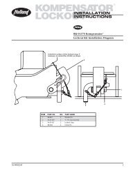
EQUALIZING BEAM MODEL IDENTIFICATION(Left Hand/Road Side Beams Shown)Measurements on this page showINCHESMILLIMETERSMODEL: AD-123 / 246 / 36924.75628.717.39441.77.03178.6DIA.1.2130.725.73653.5DIA..7619.32.25-8 UN-2ATHREAD5.75**146.1DIA.2.5063.51/2˝ (12.7mm)THICK PLATE5.0<strong>01</strong>27.0** Dimension includes spacer washer. Dimension is 5.25˝ (133.4mm) without spacers included.MODEL: AD-126 / 252 / 3787.25184.2DIA.1.2130.724.75628.725.79655.118.39467.1DIA..7619.32.25-8 UN-2ATHREADDIA.2.5063.51˝ (25.4mm)THICKPLATE5.25133.45.0<strong>01</strong>27.0MODEL: AD-130 / 260 / 3904.25108.026.50673.126.84681.7DIA.1.3434.<strong>01</strong>8.19462.0DIA..7619.32.25-8 UN-2ATHREADDIA.2.5063.51˝ (25.4mm)THICK PLATE6.0<strong>01</strong>52.45.25133.4<strong>XL</strong>-<strong>AK398</strong>-<strong>01</strong> <strong>Rev</strong>. D9
HEIGHT CONTROL VALVE ADJUSTMENTProcedure1. Prior to adjustment, drive the vehicle in a straight line forat least 2 vehicle lengths to release any possible bushingwind up.The vehicle must be on level ground and in anunladen condition. Chock the front tires to prevent thevehicle from rolling forward or backward. If vehicle isequipped with only one height control valve go to Step 3.Failure to properly supportsuspension during maintenancemay allow suspension to fall which, if not avoided,could result in death or serious injury.2. Disconnect linkages at lower brackets, push control armsto “up” position, and raise vehicle.Then position jack stands(one each side) at proper ride height between the vehicleframe and the ground.With jack stands in position, pushcontrol arms to “down” position lowering vehicle anddeflating all air from air springs and vehicle system.NOTE: It may be necessary to shim jack stands toachieve proper ride height.NOTE: It is not necessary to use air system for jacking;hydraulic or other shop lift devices may be usedto raise vehicle provided they are ofadequate size.3. Move height control arms to 45° down position for10 - 15 seconds.4. Loosen the 1/4˝ adjusting lock nuts on the height controlvalves, reconnect linkage at lower brackets, tighten to4 - 5 ft. lbs.5. Tighten the 1/4˝ adjusting lock nut on the height controlvalves 2 - 4 ft. lbs.(lubricated) torque.Remove the locating pin.FIGURE 5AD-123/126 ModelsRIDE HEIGHTAIR SPRING HEIGHTJACK STAND HEIGHT6. Pressurize the air system with a constant supply of air inexcess of 70 P.S.I.G.All air springs should inflate and thesuspension should be at a proper ride height. Inspect theair system and eliminate any air leaks.The height controlvalve may have a built-in time delay feature, therefore,several seconds may elapse prior to air flow.NOTE: If proper ride height is not obtained or air springsdo not inflate properly, check air pressure, checkfor proper piping and repeat above steps.Then,if not functioning properly, contactSAF-HOLLAND Technical Service for assistance.Do not overload the axle or suspension.If overloaded, suspension componentdamage may occur.SERVICE REPAIR KITS (SRK)PIVOTCONNECTIONWhen servicing your AD Series suspension, usethe convenient service repair kits noted below.Descriptions are found on the following pages.NOTE: One (1) SRK Required per axle.A<strong>XL</strong>E PIVOTCONNECTION(BAR PIN STYLE SHOWN)TRANSVERSE BEAMCONNECTIONFront Pivot Axle thru bolt Axle Bar Pin Transverse BeamModel Connection Connection Connection ConnectionAD-123/246/369 SRK-563 SRK-80 SRK-452 SRK-214AD-126/252/378 SRK-563 SRK-471 SRK-450 SRK-472AD-130/260/390 SRK-565 SRK-498 N/A SRK-50<strong>01</strong>0 <strong>XL</strong>-<strong>AK398</strong>-<strong>01</strong> <strong>Rev</strong>. D
SERVICE REPAIR KITS continuedNOTE:NOTE:New alignment bushings recommendedwhen alignment bushing surface becomedeformed. Refer to parts list.Item 4 is not used on former Fordproduction units.52Pivot Connection — Heavy Duty AD-123/-126 SeriesSRK-563: 481 00 427(Replaces SRK-200)ITEM PART NO. DESCRIPTION QTY.1 932 <strong>01</strong> 055 Rod Bolt 1 1 /8˝ -7 x 9.53˝ 22 934 00 506 Lock Nut 1 1 /8˝ - 7 23 900 08 252 Bushing 24 936 00 502 Spacer Washer 1 1 /8˝ 45 936 00 174 Washer Flat Narrow 1.12˝ (Hardened) 4<strong>XL</strong>-AK399-<strong>01</strong> Torque Specification Decal 1<strong>XL</strong>-AK424 AD Service Repair Kits Literature 1Pivot Connection — Heavy Duty AD-130 SeriesSRK-565: 481 00 429(Replaces SRK-499)ITEM PART NO. DESCRIPTION QTY.1 932 <strong>01</strong> 068 Rod Bolt 1 1 /4˝ -7 x 9.00˝ 22 934 00 510 Lock Nut 1 1 /4˝ - 7 23 900 08 256 Bushing 24 936 00 546 Spacer Washer 4<strong>XL</strong>-AK399-<strong>01</strong> Torque Specification Decal 1<strong>XL</strong>-AK424 AD Service Repair Kits Literature 115434Transverse Beam Connection — AD-123 SeriesSRK-214: 481 00 276ITEM PART NO. DESCRIPTION QTY.1 905 36 006 Lock Spacer 22 934 00 607 Heavy Nut 2 1 /4˝-8 23 900 08 219 Bushing 24 936 00 498 Washer – Spacer 25 936 00 533 Tab Washer 2Transverse Beam Connection — AD-126 SeriesSRK-472: 481 00 335431ITEM PART NO. DESCRIPTION QTY.1 905 36 006 Lock Spacer 22 934 00 607 Heavy Nut 2 1 /4˝-8 23 900 08 219 Bushing 24 900 36 209 Washer – Spacer 25 936 00 533 Tab Washer 252Transverse Beam Connection — AD-130 SeriesSRK-500: 481 00 364ITEM PART NO. DESCRIPTION QTY.1 905 36 006 Lock Spacer 22 934 00 607 Heavy Nut 2 1 /4˝-8 23 900 08 135 Bushing 24 936 00 498 Washer – Spacer 25 936 00 533 Tab Washer 2<strong>XL</strong>-<strong>AK398</strong>-<strong>01</strong> <strong>Rev</strong>. D11
SERVICE REPAIR KITS continuedNOTE: See illustration at bottom of page 14.Transverse Beam Connection — AD-130 SeriesSRK-564: 481 00 428ITEM PART NO. DESCRIPTION QTY.4 900 36 165 Spacer Washer 25 936 00 533 Tab Washer 23142Axle Bar Pin Connection — AD-123 SeriesSRK-452: 481 00 315ITEM PART NO. DESCRIPTION QTY.1 930 04 3<strong>01</strong> Cap Screw - Bar Pin Only 1˝- 8 x 6˝ Gr. 8 42 934 00 502 Hex Nut Lock 1˝-8 43 905 08 175 Bushing - Beam Center 24 936 00 168 Washer Flat Narrow 1˝ 85 900 <strong>01</strong> 205 Spacer Washer 45Axle Bar Pin Connection — AD-126 SeriesSRK-450: 481 00 3131ITEM PART NO. DESCRIPTION QTY.43421 930 04 3<strong>01</strong> Cap Screw - Bar Pin Only 1˝- 8 x 6˝ Gr. 8 42 934 00 502 Nut Hex Lock 1˝- 8 43 905 08 <strong>01</strong>2 Bushing – Beam Center 24 936 00 168 Washer Flat Narrow 1˝ 8NOTE: The AD-130 Series does not utilize the bar pin connection.Axle Thru Bolt Connection — AD-123 SeriesSRK-80: 481 00 124ITEM PART NO. DESCRIPTION QTY.5 3 /4˝ WIDE(146mm)1456365421 930 03 693 Hex Bolt 3/4˝- 10 x 7 1 /2˝ 22 934 00 492 Hex Nut 3/4˝ 23 900 08 008 Bushing – Beam Center 24 936 00 156 Washer Flat Narrow 3/4˝ 45 900 <strong>01</strong> 002 Adapter Bushing 46 900 <strong>01</strong> 065 Spacer Washer 4Axle Thru Bolt Connection — AD-126 SeriesSRK-471: 481 00 334ITEM PART NO. DESCRIPTION QTY.1 930 03 693 Hex Bolt 3/4˝- 10 x 7 1 /2˝ 22 934 00 492 Hex Nut 3/4˝ 23 900 08 195 Bushing – Beam Center 24 936 00 156 Washer Flat Narrow 3/4˝ 45 900 <strong>01</strong> 002 Adapter Bushing 46 900 36 210 Spacer Washer 4Axle Thru Bolt Connection — AD-130 SeriesSRK-498: 481 00 362ITEM PART NO. DESCRIPTION QTY.6˝ WIDE(152mm)5421 930 03 705 Hex Bolt 3/4˝- 10 x 8˝ 22 934 00 492 Hex Nut 3/4˝ 23 900 08 225 Bushing – Beam Center 24 936 00 156 Washer Flat Narrow 3/4˝ 45 900 <strong>01</strong> 349 Adapter Bushing 4314512 <strong>XL</strong>-<strong>AK398</strong>-<strong>01</strong> <strong>Rev</strong>. D
REPLACEMENT INSTRUCTIONSShock AbsorbersNOTE:If an oil mist covers a shock absorber, thiscondition is normal; therefore, it is not necessaryto replace the shock absorber.A certain degree ofvapor is normal and actually necessary forlubrication of the rod.To check to see if a shock isworking properly, drive the vehicle at moderatespeed for a approximately 10 minutes. Return andlightly touch the shock below the dust cover. Ifshock is hot or warm to the touch, the valvinginside the shock is working.IMPORTANT: DO NOT touch shock or injury couldoccur.1. It is recommended the vehicle be unloaded. Block vehicleto prevent rolling.Vehicle must be at approximate rideheight to assure that tension is relieved on shocks.2. Remove upper and lower mounting bolts andshock absorber.Physical contact with hot shockabsorbers may result in minor ormoderate burns to the skin.3. Replace with correct shock absorber, and reinstall bolts.4. Torque nuts. See page 4 for torque specifications.Bushings – Equalizing Beam – ReplacementThe rubber bushings in the equalizing beam may be replacedusing a hydraulic press with a capacity of 10,000 lbs. orgreater. There is a 30,000 lb. minimum for the metal sleevedAD-126 and the AD-130 axle beam hanger bushing or use aBushing Service Tool.NOTE: SAF-HOLLAND Bushing Service Tool, Part No.505 44 <strong>01</strong>2 (FIGURE 6), is available to ease removaland replacement of bushings. Contact your OEMService Center for details.To replace the bushings in an equalizing beam, first remove thebeam from the vehicle.The following procedure is recommended:1. It is recommended the vehicle be unloaded. Block thevehicle to prevent rolling. Raise vehicle frame 2˝ aboveride height and support with adequate jack stands.The height controlBushingvalve(s)Servicemay beToolused to raise vehicle.Failure to properly supportsuspension during maintenancemay allow suspension to fall which, if not avoided,could result in death or serious injury.2. Exhaust air by:A. Using the height control valve – disconnect link atlower connection, then rotate control arm to exhaust(approx. 45° down) position.Drain all air from air reservoir, orB. Disconnecting air supply line from air spring.3. Disconnect shock absorbers, and air springs atlower connections.4. Disconnect transverse beam, axle connection andpivot connection.NOTE the position of the following:• Pivot: Note spacer placement (see Step 7 on page 5).• Axle: Note the pinion angle.• Transverse beam: Note spacer position and orientation.5. Support the beam. Press out old bushings with ahydraulic press.During the pressing operation,the beam support fixture mustbe securely mounted to the hydraulic press toprevent the beam from shifting abruptly which, ifnot avoided, may result in minor or moderate injury.6. Clean out bushing receptacles in beam of all foreignmaterial before pressing new bushings into the beam.NOTE: DO NOT use an open flame or other heatsource to remove the bushings.7. Inspect all parts for wear, cracks or field welds – repairor replace.IMPORTANT: NEVER repair a cracked equalizing beam.DO NOT weld cracks. Secondary weldfailures during use may cause loss ofvehicle control.Failure to replace a crackedequalizing beam may cause lossof vehicle control which, if not avoided, could resultin death or serious injury.8. Lubricate the new replacement bushing with an approvedrubber lubricant.NOTE:FIGURE 6Bushing Service Tool FIGURE 7The bushing service tool can be usedon all bushings, including pivotconnections and transversebeam connections.Part No. 505 44 <strong>01</strong>2DO NOT use an oil-based lubricant, soap orbrake fluid, as it can cause damage to therubber. With the beam supported, press thenew bushing into the beam. (Refer to Step #9.)Bushing Centered in BeamFront Pivot andBeam CenterBushing Replacement9. NOTE: Bushings are to be centered in the equalizing beamand bar pin bushings should match prior orientation forpinion angles.10. Reassemble new or rebushed equalizing beam to framebracket. Install spacer washers same as prior configuration.11. Reassemble axle connection and the transverse beam.12. Reconnect air springs, shock absorbers, height controlvalve link.<strong>XL</strong>-<strong>AK398</strong>-<strong>01</strong> <strong>Rev</strong>. D13
REPLACEMENT INSTRUCTIONS continuedBushings – Equalizing Beam – Replacement cont.13. Re-install, if necessary, wheels, camshafts and tires. Removejacks and stands, and build air reservoir pressure in excessof 70 P.S.I.G.. Check for proper ride height, page 10.Bushings – Transverse Beam – Replacementcont.FIGURE 8Transverse Beam Bushing ReplacementBushings – Transverse Beam – Replacement1. NOTE: Refer to and perform procedure 1 and 2 ofBushings – Equalizing Beam – Replacement (this page)before proceeding.2. Disconnect air springs at the lower connections.3. Remove transverse beam.NOTE the position of the following:• Transverse beam: Note spacer position and orientation.4. Support the beam. Press out the old bushings with ahydraulic press capable of 10,000 lb. force.NOTE: The transverse beam bushing may featurea split core to enhance removal. The split coreallows the bushing to be pried apart aftercutting through the rubber.During the pressing operation,the beam support fixture must besecurely mounted to the hydraulic press toprevent the beam from shifting abruptly which, ifnot avoided, may result in minor ormoderate injury.NOTE: DO NOT use an open flame or other heatsource to remove the bushings.5. Clean out bushing receptacles in beam of all foreignmaterial before pressing new bushings into the beam.Inspect all parts for wear, cracks or failed welds – replace.IMPORTANT: NEVER repair a cracked transverse beam.DO NOT weld cracks. Secondary weldfailures during use may cause loss ofvehicle control.Failure to replace a crackedtransverse beam may cause lossof vehicle control which, if not avoided, could resultin death or serious injury.6. Lubricate the new replacement bushing with an approvedrubber lubricant.NOTE: DO NOT use an oil-based lubricant, soap orbrake fluid, as it can cause damage to the rubber.With the beam supported, press the new bushing intothe beam until it is centered in the bushing receptacle.7. Reassemble the rebushed transverse beam on the equalizingbeam. Install spacer washers same as prior configuration.SPACERWASHERTRANSVERSE BEAMAFTERTORQUING,BEND TABOVER SIDEOF NUTBUSHINGLOCK SPACERTAB WASHER2 1 /4˝ HEAVY NUT8. After the nut is torqued (see the Torque Chart onpage 4), bend the tab of the washer over sideof the T-beam nut.9. Reconnect air springs.10. Re-install, if necessary, wheels, camshafts and tires.Remove the jack stands and build air reservoir pressurein excess of 70 P.S.I.G. Check for proper ride height.Suspension Air SpringsIMPORTANT: Air springs must be replaced with the properair spring for your application. Check the topmetal plate for the part number. If the partnumber is unidentifiable, reference the chassisbuilder vehicle build specifications.NOTE: For further assistance with air springpart number identification contactSAF-HOLLAND technical assistanceat 888-396-65<strong>01</strong>.1. Prior to removing the air spring, the vehicle must beunloaded. Support the vehicle frame with adequate jackstands at the approximate ride height.Failure to properly supportsuspension during maintenancemay allow suspension to fall which, if not avoided,could result in death or serious injury.2. Exhaust the air from the suspension system.Exhaustair by:A. Use height control valve – disconnect link at lowerconnection, then rotate control arm to exhaust(Approx. 45° down position).Drain all air from reservoir, orB. Disconnect the air supply line from the air spring.3. Disconnect and remove old air spring assembly.4. Install new air spring assembly and properly torquefasteners. See Torque Chart on page 4.NOTE:AD-123 air springs require a nut on the rearstud only on the lower connection.14 <strong>XL</strong>-<strong>AK398</strong>-<strong>01</strong> <strong>Rev</strong>. D
REPLACEMENT INSTRUCTIONS continuedSuspension Air Springs cont.5. Reconnect air supply line and link connections.6. Remove jacks or stands.Suspension Air Springs cont.7. Build suspension air supply system in excess of70 P.S.I.G. check for leaks.8. If ride adjustment is necessary, refer to page 10 for theproper procedure.Frame BracketsThe original orientation of the frame bracket must be maintainedwhen replacing the frame bracket. Frame brackets for theAD-123/246/369 and the AD-126/252/378 models may beinstalled by the chassis builder in reverse orientation (e.g.: aLeft Hand [LH] or roadside frame bracket installed on the RightHand [RH] or curbside vehicle frame rail; or a RH frame bracketinstalled on the LH vehicle frame rail.) Examples belowdepict a typical and a reverse frame bracket installation.TheAD-130/260/390 models utilize a symmetrical frame bracketthat can be used for both left- and right-hand orientations.Original chassis builder installed frame brackets are drilled tochassis builder specifications and have a unique 8-digit partnumber.This part number can be determined by using thechassis builder Service Network. Identify the vehicle's VehicleIdentification Number (VIN) or obtain kit number from theserial number tag located on the transverse beam under theair spring plate (see page 3).A universal (UNDRILLED) - LH (900 18 578) or RH (900 18 579)frame bracket is available for AD-123/246/369 and AD-126/252/378models.These universal (undrilled) frame brackets provide theflexibility required to replace a variety of frame brackets.Theseframe brackets require one Service Repair Kit (SRK-563) and(2) 900 08 252 Alignment Bushings per frame bracket. Universalframe brackets are less pre-drilled mounting holes and willrequire back drilling at installation. Position the new undrilledframe brackets in the proper mounting location and use theexisting frame bolt holes as a drill pattern.The AD-130/260/390 models utilize a symmetrical, drilledframe bracket and cannot be ordered as undrilled.The axle alignment feature will allow approximately ±1/4˝ (6.35mm)of axle alignment fore and aft for a 1/2˝ (12.7mm) total.FIGURE 9Frame Bracket InstallationTypical InstallationLH (roadside) frame bracket onLH vehicle frame rail<strong>Rev</strong>erse InstallationRH (curbside) frame bracket onLH vehicle frame railVEHICLE FRONT<strong>XL</strong>-<strong>AK398</strong>-<strong>01</strong> <strong>Rev</strong>. D15
REPLACEMENT INSTRUCTIONS continuedFrame Bracket continuedFRAME BRACKET INSTALLATION1. Prior to removing the frame bracket, the vehicle must beunloaded. Support the vehicle frame with adequate jackstands at the approximate ride height.Failure to properly supportsuspension during maintenancemay allow suspension to fall which, if not avoided,could result in death or serious injury.2. Exhaust the air from the suspension system.Exhaust air by:A. Use height control valve – disconnect link at lowerconnection, then rotate control arm to exhaust(Approx. 45° down position), orB. Disconnect the air supply line from the air spring.3. Disconnect frame bracket and remove. Make note of thespacer washer placement for proper re-assembly. Refer toStep 7 on page 5.4. Replace pivot bushing if necessary.5. Clamp new frame brackets in proper position. Backdrill mounting holes, use existing frame mounting holesas pattern. (This applies to undrilled replacementframe brackets.)NOTE: 5/8˝ min. mounting bolts required. If holesin frame are worn, drill to next larger sizenecessary. Fasten frame bracket to framewith Grade 8 min. bolts and torque tospecifications. Use a hardened washerunder the head of the bolt and nut.6. Reassemble pivot connection. Position spacer washers aspreviously noted in Step 3.4. “Adjustable” frame brackets – adjust axle alignment bysliding alignment blocks fore/aft (see FIGURE 2).Torqueto specifications listed in Torque Chart on page 4.5. Weld alignment blocks on both sides of the adjustableframe bracket (see FIGURE 2).IMPORTANT: A minimum 3-minute cool down period isrequired after welding connection beforere-applying torque to pivot bolt nut.6. Re-torque the cooled down pivot connection on the“Adjustable” frame bracket to the specifications listedin Torque Chart on page 4.FIGURE 10Installed AD Series SuspensionTorque DecalFrameBracketPivotConnectionEqualizingBeamRIDEHEIGHTFIGURE 11“Adjustable” Frame BracketA<strong>XL</strong>E ALIGNMENT PROCEDURESNOTE: The following steps assumes that the pivot connectionis assembled with the proper hardware based onthe frame width and frame bracket type specifiedfor the application.Perform the following procedures for each axle.1. Determine whether the frame bracket is “fixed” (alignmentblock centered and welded to the frame bracket bySAF-HOLLAND) or “adjustable” (alignment block shippedloose by SAF-HOLLAND) (see FIGURE 11).NOTE:Typically, suspension kits are shipped to thechassis builder with one frame bracket “fixed”and one frame bracket “adjustable”. Somechassis builder’s however specify bothframe brackets as “adjustable”.WELDS – weld thealignment block tothe frame bracketwith three (3) 1˝(26mm) welds equallyspaced around thecircumference of thealignment block.Allow the alignmentblock to cool for atleast 3 minutes andthen re-torqueconnection asspecified in theTorque Chart foundon page 4.CENTERLINE1/2˝(13MM)1/4˝(6MM)2. SAF-HOLLAND recommends that the chassis be set at thespecified Ride Height prior to axle alignment(see FIGURE 10).3. “Fixed” frame bracket – torque pivot connection to thespecifications listed in Torque Chart on page 4.ALIGNMENT BLOCK –1/2˝ (13mm) totaltravel for alignment(1/4˝ fore and 1/4˝ afttravel from alignmentslot centerline).16 <strong>XL</strong>-<strong>AK398</strong>-<strong>01</strong> <strong>Rev</strong>. D
AD SERIES SUSPENSION TORQUE AND LUBRICATION IDENTIFICATIONFIGURE 12New AD Series Torque Specification Decal (<strong>XL</strong>-AK399-<strong>01</strong>)GO THE DISTANCE.AD SERIES SUSPENSION TORQUE SPECIFICATIONSFastenerSizeTorque Ft. Lbs.(Nm)Pivot Connection* Transverse Shock Air SpringAD-123/126 AD-130 Beam** Absorber Attachments1 - 1/8" 1 - 1/4" 2 - 1/4" 3/4" 3/4"* IMPORTANT: SEE PIVOT BOLT HEADPivot BoltHeadmarked“NEWAY”REQUIRESlubrication.600 700 525 150 35(813) (949) (711) (203) (47)ALL TORQUE SPECIFICATIONS ARE + 5%. TORQUESARE WITH CLEAN, LUBRICATED THREADS. ALWAYSAPPLY TORQUE TO NUT IF POSSIBLE.Pivot BoltHead marked“HOLLAND NEWAY”DOES NOTREQUIRElubrication.** AFTER APPLYING PROPER TORQUE TO THETRANSVERSE BEAM NUT, FOLD THE WASHERTAB OVER A FLAT SIDE OF THE NUT.REQUIRED RE-TORQUING SCHEDULE:• ALL FASTENERS AFTER FIRST 100 HOURS OFSERVICE OR 5,000 MILES.• 50,000 MILE INTERVALS, ROUTINE P.M., ORBRAKE RELINING.Copyright © 2002 • The <strong>Holland</strong> <strong>Group</strong>, <strong>Inc</strong>.900 44 236 • <strong>XL</strong>-AK399-<strong>01</strong><strong>XL</strong>-<strong>AK398</strong>-<strong>01</strong> <strong>Rev</strong>. D17
TROUBLESHOOTINGProblemAll air springs flat (no air).Air springs deflate rapidly whenvehicle is parked.Ride height too high or too low.Air springs ruptured.Air spring failed.Air spring(s) fail to fully deflate when allweight is removed from the suspension.Front pivot connection worn and loose.Shock absorber failures.Excessive tire wear.Possible Cause and RemedyInsufficient air pressure in the vehicle air system. Check the air pressuregauge on instrument panel. If air pressure is low, run the engine until a minimumpressure of 70 P.S.I.G. is indicated on the gauge. If air pressure is 70 P.S.I.G. or aboveand the air spring is not inflated, check the pressure protection valve.Air leakage from the suspension air system or the air brake system. Test forair leakage due to loose fittings or damaged air lines, air springs, brake actuatorsor control valve.Tighten loose fittings to stop leakage and/or replace worn ordamaged parts.Air leakage from the suspension air system. Test for air leakage due to loosefittings between air tank and air suspension or damaged air lines, air springs orheight control valve.Apply a soapy solution to connections and air springs ifnecessary to check for bubbles (leaks).Tighten loose fittings to stop leakageand/or replace worn or damaged parts with new ones.Height control valve out of adjustment. Re-adjust the height control valve.Tires, rims, chains or other objects are rubbing the air spring. Check theclearance between the air spring and the tire. If the tire, rim, chains or otherobjects contact the inflated air spring when the vehicle is loaded, change tonarrower tires and rims to provide clearance for tires with chains (contact yourvehicle manufacturer for recommendations).Continual or repeated over-extension of the air spring. Check for propershock part number.Visually inspect for broken or loose shock absorber or shockabsorber mounting bracket. Reconnect loose parts and replace any defective parts.Check the adjustment of the height control valves.Air spring(s) worn out. Replace.Restricted air lines(s) between the height control valve and the air spring(s).Disconnect the height control valve linkage and rotate the actuating lever tothe 45° down position. If the air spring(s) remain inflated, check for pinchedor blocked line(s).Check pivot connection for worn bushings or looseness by inserting a 2´ prybar between the frame bracket and nose of the equalizing beam.Visually check formovement while moving the bar back and forth. If .25˝ or more movement is detected,disassemble the connection and visually inspect the rubber bushing. Replace thebushing if wear is detected. If the bushing appears to be okay, reassemble the connectionand—with the suspension set at the proper ride height—torque the connection toproper specification.Worn out due to length of service. Replace pivot connection.Axle alignment block not welded properly. Replace worn parts, realign, torqueand weld to specifications.Elongated eyes/over-extension. Mis-located shock brackets. Improper lengthshocks installed.Axles mis-aligned. Re-align axles per vehicle manufacturer’s recommendations.Suspension has alignment blocks located on the frame bracket pivot connectionsfor axle alignment.Alignment blocks are welded in position, weld must be removedprior to re-alignment. Reweld after alignment.Worn pivot or axle bushings. Rebush with proper bushing, refer toreplacement instructions.continued18 <strong>XL</strong>-<strong>AK398</strong>-<strong>01</strong> <strong>Rev</strong>. D
TROUBLESHOOTING continuedProblemVehicle unstable or handles poorly.Possible Cause and RemedyLoose frame bolts or attachments. Tighten frame bolts and attaching parts toproper specifications.Cracked or loose frame crossmembers. Repair or replace damaged framemembers and torque all nuts and bolts to proper torque specifications.Check the ride height. Readjust if necessary.Loose transverse beam connection. Replace worn bushings, retorque tospecifications. Refer to replacement instructions.Wrong bushings.Loose or worn pivot connection. Check pivot connection for worn bushings orlooseness by inserting a 2´ pry bar between the frame bracket and nose of the equalizingbeam.Visually check for movement while moving the bar back and forth. If .25˝ ormore movement is detected, disassemble the connection and visually inspect therubber bushing. Replace the bushing if wear is detected. If the bushing appears tobe fine, reassemble the connection and—with the suspension set at the proper rideheight—torque the connection to proper specification.Loose or worn bar pin axle connection (rubber wear). Check axle connection forworn bushings or looseness by inserting a 2´ pry bar between the top of the equalizingbeam and bottom of the axle adapter.Visually check for movement while moving thebar back and forth. If .25˝ or more movement is detected, disassemble the connectionand visually inspect the rubber bushing. Replace the bushing if wear is detected. If thebushing appears to be fine, reassemble the connection and—with the suspension setat the proper ride height—torque the connection to proper specification.Loose or worn bar pin axle connection (bar pin wear). The bar pin subassemblyfreely rotates within the bore of the bushing core. New bar pin bushing assemblieshave a “total” gap of 0.085˝ (gaps exist at both ends of the bushing core). If the sumof the two gaps is greater than 0.140˝, replace the bushing.Contact your chassis builder for recommendations if these possible causes and effects do not solve the vehicle handling problem.<strong>XL</strong>-<strong>AK398</strong>-<strong>01</strong> <strong>Rev</strong>. D19
Engineering Your Road to SuccessSAF-HOLLAND USA, <strong>Inc</strong>.SAF-HOLLAND Canada Limited888.396.65<strong>01</strong> Fax 800.356.3929 519.537.3494 Fax 800.565.7753Western Canada604.574.7491 Fax 604.574.0244Copyright © January 2008-SAF-HOLLAND, <strong>Inc</strong>. All information contained in this document was correct at time of copyright, and is subject to change without notice. All rights reserved.20 www.safholland.us<strong>XL</strong>-<strong>AK398</strong>-<strong>01</strong> <strong>Rev</strong>. D