Simplified Control Technique for Three-Phase Rectifier ... - Ivo Barbi
Simplified Control Technique for Three-Phase Rectifier ... - Ivo Barbi
Simplified Control Technique for Three-Phase Rectifier ... - Ivo Barbi

You also want an ePaper? Increase the reach of your titles
YUMPU automatically turns print PDFs into web optimized ePapers that Google loves.
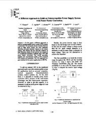
IEEE ISIE 2006, July 9-12, 2006, Montreal, Quebec, Canada<strong>Simplified</strong> <strong>Control</strong> <strong>Technique</strong> <strong>for</strong> <strong>Three</strong>-<strong>Phase</strong> <strong>Rectifier</strong>PFC Based on the Scott Trans<strong>for</strong>merA.A. Badin* and I. <strong>Barbi</strong>**Federal University of Santa CatarinaPower Electronics InstituteP.O.Box 5119CEP:88040-970Florianopolis, SC-BrazilE-mail: alceu@inep.ufsc.br* and ivobarbi@inep.ufsc.br**Abstract: In this work, a new simplified control is proposed <strong>for</strong>three-phase rectifier based on the Scott Trans<strong>for</strong>mer with splitDC bus. The control technique loop is independent <strong>for</strong> each boostthat integrates the rectifier. There<strong>for</strong>e, it makes possible with twosingle-phase boosts to obtain a unity power factor three-phaserectifier. This rectifier is particularly attractive when galvanicisolation and minimum number of active switches are required. Itis used PWM with instantaneous average current control. Besidesit has two voltage control loops that regulate the output voltageand the split DC bus. In this paper will be presented analysis,simulation and experimental results <strong>for</strong> the three phase rectifierand the control technique proposed.I. INTRODUCTIONIn recent years, the growth in the use of electrical equipmenthas resulted in more stringent international standards and utilityrequirements to ensue that line current harmonic content ofequipment connected to the ac mains is limited [1]. If suchstandards did not exist, then sensitive electrical equipmentconnected to the mains would be damaged as a result of adistorted main voltage. <strong>Three</strong>-phase ac-dc converters operatingfrom the ac utility mains have the potential to inject currentharmonics into the ac mains that may cause such a distortedvoltage. These harmonics can be significantly reduced if theinput power factor is corrected by shaping the input current ineach of the three phases so that it is sinusoidal and in phasewith the phase voltage. Due to this, switch-mode rectifiers <strong>for</strong>power factor correction have gained considerable attention.In addition to unity power factor, safety and robustness alsoare important <strong>for</strong> medium-power and high-power. Due to thatisolated systems in low frequency are used. The isolatedrectifiers have been widely used in the electrochemical industryand petrochemical industry.The three-phase rectifier based on the Scott Trans<strong>for</strong>mer hasbeen proposed by [2], and has been analyzed in its practicalaspects by [3] and [4]. In this paper, the unity power factorthree-phase rectifier with split DC-bus and a simplified controlloop technique, based on the Scott trans<strong>for</strong>mer, is presented.The proposed topology is show in the Fig. 1. This rectifierhas a split DC-bus and switches voltages are Vo/2. The controlmethod employed to control the currents of the two boostinductors, LT and LM, is instantaneous average current control.Each rectifier presents an independent current loop with anindividual reference current, generating sinusoidal secondarycurrents in phase with their respective secondary voltages.Each rectifier also presents an independent voltage loop andindividual reference voltage. The output voltage compensatorsare used to determine the amplitudes of the reference currents.LTDTVVBvcABIB(t)TTt+LT'A~i)V ecT(t) + 0oTsc mVMOLm Dm . ;tV0(t)Fig. 1: Unity power factor isolated three-phase rectifier a newseries-connection technique.II. STEADY-STATE ANALYSISThe Scott connection is realized with two single phasetrans<strong>for</strong>mers, TM and TT. The primary windings are fed by twodifferent voltages, VAo(t) e VcB(t), that are generated from asymmetrical three phase system VA(t) VB(t) e Vc(t). Theconnection is represented at Fig. 2(a).VsecT(t) and VsecM(t) represent a two phase voltage system,with a phase angle 900 between then. The phasor diagram isrepresented at Fig. 2(b).In the unity power factor isolated three-phase rectifiertheoretical study, only the secondary circuitry will be takeninto account. There<strong>for</strong>e, the secondary windings of the Scott1-4244-0497-5/06/$20.00 C 2006 IEEE 931
trans<strong>for</strong>mer are considered to be ideal AC power sources. Thefull-bridge diode rectifiers were substituted by power sourcesthat represent the rectified secondary voltage VmiT(t) andVinM(t). The topology of Fig. 1 can be reduced to the circuit ofFig. 3.~AV0(t)I~~~~~/-.d I~~, \"\VsecT(t)vsecu(t)ICkL)(a)Fig. 2: (a) Scott connected trans<strong>for</strong>mers, (b) phasor diagramof Scott Trans<strong>for</strong>merThe secondary voltages of the Scott trans<strong>for</strong>mer are sine andcosine wave<strong>for</strong>ms [5]. There<strong>for</strong>e, the rectified voltages at theinputs of the boost converters are:JKnT (t) VP Isin(w *t)|KnlM(t) VPI cos(w *t)|The instantaneous average duty cycles of the switches are:VdT(t) = 1- ' Isin(w .t) (3VOTdM(t) = 1- -VoMcos(w.t)|The purpose of using a boost PFC is to correct the powerfactor of the structure by <strong>for</strong>cing the inductor current to followthe shape of the rectified secondary voltage. The boost inductorcurrents are, there<strong>for</strong>e, images of the rectified secondaryvoltages of (1) and (2)ILT (t) = ILP Isin(w.t)ILM (t) = ILP |cos(w .t)Where:ILp is the peak value of the boost inductor current.(b)(1)(2)3)(4)(5)Fig. 3: <strong>Three</strong>-phase rectifier equivalent circuit.The current through the switch of a boost converter is thecurrent through the boost inductor multiplied by the duty cycle.In the same manner, the current through the boost diode is thecurrent through the boost inductor multiplied by thecomplementary duty cycle. There<strong>for</strong>e, the currents through theboost diodes are defined as:IDT (t) = [1 -dT (t)1IDM (t) = []- dM (t)]LT (t)ILM (t)(7)(8)Substituting (3), (4), (5) and (6) into (7) and (8) it isobtained:VIDT (t) = ILP * o *sin(w.t)2oTIDM (t)'= LPV* *cs toM(9)(10)Considering a balanced load, the resulting equivalent circuitcan be seen in Fig. 4.ni(6) V0(t)Fig. 4: Equivalent circuit of the output filter.932
For the equations of the node n, and n2, is obtained thedifferential equations given by:PWMTCT . + = IDT (t)CMd(Vm (t))DMdit(t)Solving the differential equations is obtained:(1 1)(12)VOT (t)VOM (t) -:ILP . V .*R° .(1+4.W RO2 . COT2 +f (t))2 +8. W RO2. COT2ILP IL P RO R (1+ (+42()W2. RO COM2 + V2OM2 +8. W RO2 COM2(13)(14)Where VJ(t)=-cos(2.w.t)-2w]ROCOT .sin(2.w.t)and V2(t)= cos(2.w t)+2. w RO COM sin(2 w* t)-The V0(t) is defined as the sum of the capacitors voltage ofthe output filters:VO (t) = VOT (t) + VOM (t) (15)Substituting (13) e (14) into (15)obtained that:V0(t) = 2-IL'Pand supposing CT=CM is-KVR (16)The high frequency components of current were discardedby considering only the instantaneous average values of theboost diode currents. Even so, ideally, the high frequencycomponents of the current would flow through outputcapacitor, leaving the DC component free to flow through theload, resulting in a constant voltage output.The output power of the rectifier is constant, which is anadvantage of the topology since the output capacitor does notneed to cope with any low frequency power fluctuation.III. CONTROL STRATEGYEach boost PFC presents its own current control by means,as [6] and [7]. The external voltage loop is used <strong>for</strong> each boostPFC in order to guarantee the balance of the split DC busvoltage.A complete block diagram of the control loops can be seenin Fig. 5.Fig. 5: Complete block diagram of the control loops.Where:Vref is the reference voltage, IrefT and IrefM are the referencescurrent, CVM(s) and CVT(s) are the voltage compensator, CIT(S)e CIM(s) are the current compensator and VOT e VOM, are theoutput voltage of each boost PFC.A. Current loopInstantaneous average current control is one of the mostwidely methods used to correct the power factor of rectifiers.This technique consists of monitoring and controlling the boostinductor current by means of high frequency switching, so thatcurrent follows a sinusoidal reference with minimum error.The current-to-control transfer function of the converter(H11T(s) and HiM(s)) was obtained from Fig. 4, and can be seenin (17).I, (s) =HVT (S) =dT(S)ILM (s)= HIM (S) =dAl(S)The current loop isS.LTs*LM(17)(18)considered to be much faster than thevoltage loop and, there<strong>for</strong>e, its closed-loop transfer functioncan be simplified and represented as the current sensorconductance 1/R,h. This simplification does not compromisethe dynamics of the voltage loop because the simplified andcomplete closed-loop transfer functions of the current loop areidentical at the frequency range of the voltage loop.933
B. Voltage loopsTo control the voltage it is used two voltage control loops. Avoltage control loop is applied <strong>for</strong> each boost PFC. A blockdiagram of the voltage loops can be seen in Fig. 6.Both transfers functions of the plant voltages loop wereobtained from model of Fig. 4 and can be seen in (19) and (20).The equivalent series resistance (Rse) of the output capacitorwas taken into account.V *R *RseH (s) 0VO . (R0 + Rse)V *R *RseV0 *(R + Rse)Hv(s)= v 0(S+ 1CM*Rse (19)C,CM(RO +Rse)jJCT .RsejCT .(RO + Rse)j,(20) 41CVIl-2 ' li1t 1 l vp144 P 1 v'l 1630ms 635ms 640ms 645ms 650ms 655ms 660ms 665ms 670msTimeFig. 7: Line currents IA(t), IB(t) and Ic(t).In Fig. 8 shows the output voltage of the each boost PFC,VoT(t) and VoM(t), and output voltage VO(t).420VII40CV-390V-VOT201V1''#aj380V- 64Cms 645ms 650ms 655msTime66ims 66 ms 670msFig. 8: Output voltage VoT(t), VoM(t) and VO(t)/2.The second simulation aims to verify the per<strong>for</strong>mance of thecontrol loops when the rectifier suffers load variations, from50% of the rated load to 100%. The results <strong>for</strong> the line currentscan be seen in Fig. 9.IrefvtIVrefFig. 6: Voltage loop block diagram.IV. SIMULATION RESULTSThe results of two simulations are presented to check thevalidity of the study until this point. The first simulation aimsto verify the per<strong>for</strong>mance of the current loop.In Fig. 7 shows the line currents IA(t), IB(t) and Ic(t).The total harmonics distortions (THD) of the line currents<strong>for</strong> full load operation are: THDIA=3.15%, THIDIB=3.10% eTHDIc=3.011%-30A 350ms 360ms 370ms 380ms 390ms 400ms 41Oms 420ms 430ms 440ms 450msTimeFig. 9: Line currents after a 50% increase in the load.In Fig. 10 shows the output voltage of the each boost PFC,VoT(t) and VoM(t), and output voltage VO(t), when the rectifiersuffers a load variations, from 50% of the rated load to 100%.934
410V405VThe THD of the line currents were: 4.7%, 4.8% and 4.5%.They are near sinusoidal in shape. The power factor per phasewas: 0.99, 0.99 and 0.99 respectively.400V395VI390V385VV380V 0.75s 0.80s 0.85s 0.90s 0.95s 1.OOs 1.05s 1.1OsTimeFig. 10: Voltages VoT(t) and VoM(t) to a load unbalanced.V EXPERIMENTAL RESULTSA laboratory prototype of the isolated three-phase rectifierbased on the Scott trans<strong>for</strong>mer with split DC bus wasimplemented to prove the theoretical studies. Both of the PFCmodules are controlled by Unitrode UC3854B. The designspecifications of the prototype can be seen in Table 1.Table 1: Design specifications.ParameterValueLine frequency60 HzRMS line voltage 380 VRated power12 kWOutput voltage 800 VdcSwitching frequency 20 kHzFig. 11 show a photograph of the laboratory prototype.Fig. 12:Fig. 13:<strong>Phase</strong> voltage VA(t) (IOOV/division) and currentIA(t) (20A/division)a .f . - . _0 \.1. .. .. , .....tN .., ... ..E ... ..,... ,....: ..... ...:...... A. ..F ..:....:...;4:... tI) IB 2a v S mlS2i VP ",1 ,V q rpi;. I, , ,, . l<strong>Phase</strong> voltage ViE(t) (IOOV/division) and currentIiE(t) (20A/division)Fig. 12, Fig. 13 and Fig. 14 show the experimental results ofthe 12 kW prototype. The THD of the line voltages were3.05%, 3.44% and 3.68%.Fig. 14:<strong>Phase</strong> voltage Vc(t) (IOOV/division) and currentIc(t) (20A/division)Fig. 15 show the input currents IT(t) and IM(t) of each PFCwhich are 900 phase-shifted and the amplitudes are equal andthe output power equal.935