8923 PROFIBUS Repeater PLR1.1 - ALPAT
8923 PROFIBUS Repeater PLR1.1 - ALPAT
8923 PROFIBUS Repeater PLR1.1 - ALPAT

You also want an ePaper? Increase the reach of your titles
YUMPU automatically turns print PDFs into web optimized ePapers that Google loves.
8 923UNIGYR ®<strong>PROFIBUS</strong> <strong>Repeater</strong><strong>PLR1.1</strong><strong>PROFIBUS</strong> repeater designed for the compensation of line losses and for signalquality refreshing in extensive and/or widespread <strong>PROFIBUS</strong> networks.UseNoteThe <strong>PROFIBUS</strong> repeater is used in UNIGYR communication networks for:• The extension of <strong>PROFIBUS</strong> sections having the standard length of 1200 m• Interfacing secondary branches, e.g. in networks having a star- or treelike structureThe repeater is also suitable for use in other bus networks that comply with the<strong>PROFIBUS</strong> standard to DIN 19245, part 1.Functions• Adjustable rate of transmission• Remote supply for another <strong>PROFIBUS</strong> repeater (standby power supply in the eventthe AC 24 V operating voltage at a <strong>PROFIBUS</strong> repeater fails)Type summary<strong>PROFIBUS</strong> repeater<strong>PLR1.1</strong>AccessoriesTerminal covers, if required, are to be ordered as separate items:Terminal covers (short) 4 111 2183 0Terminal covers (long, two of)ARG81.1EquipmentcombinationsType of equipment Type reference Data sheet<strong>PROFIBUS</strong> terminator PUR1.1U 8023Communication set PAK1.1... 8271PC communication card PLU1... 8555Siemens Building Technologies CM2N<strong>8923</strong>E / 10.1999Landis & Staefa Division 1/6
Technical designTransmissioncharacteristicsThe <strong>PROFIBUS</strong> repeater is a bidirectional line amplifier whose transmission facility isautomatically controlled by the protocol.When the bus is idle, both bus interfaces are switched to the receiving mode.For applications other than <strong>PROFIBUS</strong>, the rate of transmission can be changed.Redundant powersupplyTo ensure entire bus sections will not be isolated should the AC 24 V operating voltagefail, the electronics' DC voltage supply is redundant; this means there is standby poweravailable. For this purpose, the power supply section of the <strong>PROFIBUS</strong> repeater is sizedsuch that it can power a second repeater across the maximum line length, in addition toits own power requirements.The second pair of wires of the <strong>PROFIBUS</strong> wiring is used to interconnect the supplylines of all repeaters on the DC voltage side, that is, they are switched in parallel. Onewire, "UG", also serves for potential equalization between the individual partnersconnected to the bus and as a ground wire for the power supply to the repeater. Theother wire, "UR", carries the positive potential of the repeater's power supply.Remote supply voltagesThe remote supply voltage can be selected: DC 28 V, DC 5 V, or 0 V. DC 28 V is usedfor <strong>PROFIBUS</strong> applications with UNIGYR, DC 5 V conforms to the <strong>PROFIBUS</strong>standard, and the 0 V-position is for use in cases where no remote supply is required.Mechanical designCasingFrontScrew terminalsShorting plugs forremotepower supplyTerminal coversThe <strong>PROFIBUS</strong> repeater is accommodated in a casing designed for installation incompliance with DIN 43880. It can be snapped on standard mounting rails or screwedon a wall.The unit front carries the type plate with the connection diagram, the selector for the rateof transmission (Baud rate), and the signal lamps for operating voltage and busoperation.The screw type terminal bases are plugged in and can be removed so that a <strong>PROFIBUS</strong>looped via the connection terminals will not be disrupted should it be necessary toreplace the repeater when doing service work.On the printed circuit board at the top of the unit there are eight pins with shorting plugsfor the two sections of the bus. This facility is used to select the remote supply voltagefor another <strong>PROFIBUS</strong> repeater: DC 28 V, DC 5 V, or 0 V. For details, refer to"Technical design". The unit is supplied with the shorting plugs set for DC 28 V<strong>PROFIBUS</strong> applications of the repeater.When mounting the repeater outside the control panel or when using it without theprotective casing, there are terminal covers available which must be ordered separately.There is a short version for protecting the pins at the top and a long version for theconnection terminals at the bottom of the unit.CM2N<strong>8923</strong>E / 10.1999Siemens Building Technologies2/6 Landis & Staefa Division
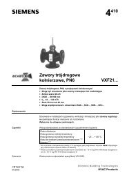
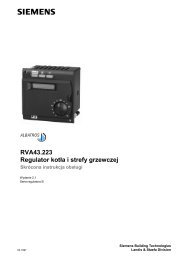
Front view128V 0V 5V 28V 0V 5V234S1H29.6 kb/s19.2 kb/s64.0 kb/s93.75 kb/sH3Landis & Staefa<strong>PLR1.1</strong>Assembled in SwitzerlandSiemens Building Technologies24V AC ± 20%10VA 50/60HzT 50 °C24V ACH1UR1 UG1 UP1 UN1 UR2 UG2 UP2 UN2 G G05<strong>8923</strong>Z031 X1,X2, shorting plugs for selection of remote supply voltage2 Selector S1 for adjustment of rate of transmission (Baud rate)3 Signal lamp for data traffic on bus section 24 Signal lamp for data traffic on bus section 15 Signal lamp for AC 24 V operating voltageWith terminal coversfitted1S1H29.6 kb/s19.2 kb/s64.0 kb/s93.75 kb/sH3Landis & Staefa<strong>PLR1.1</strong>Assembled in SwitzerlandSiemens Building Technologies24V AC ± 20%10VA 50/60HzT 50 °C24V ACH1UR1 UG1 UP1 UN1 UR2 UG2 UP2 UN2 G G02<strong>8923</strong>Z041 Terminal covers (short)2 Terminal covers (long)NoteTerminal covers are to be ordered as separate items (refer to "Type summary").Engineering notesSTOPCorrect useData sheet 8023, "<strong>PROFIBUS</strong>", contains system-related engineering know-how andnotes. It should be read before reading the following sections while paying specialattention to the information relating to safety.Within the overall system, the <strong>PROFIBUS</strong> repeater must always be used on applicationsas described in the brief description on the front page and in the chapters "Use","Engineering notes" and "Technical data" of the present data sheet. Also, the relevantchapters of data sheet 8241, "Universal Provess Units PRU1..." should be observed.The sections of this chapter identified by a warning sign contain additional requirementsand restrictions relevant to safety. They must be observed to ensure the safety ofpersons and objects.Siemens Building Technologies CM2N<strong>8923</strong>E / 10.1999Landis & Staefa Division 3/6
MountinglocationNumber of repeatersper segmentWiringDocumentation on<strong>PROFIBUS</strong>If, in exceptional cases, the <strong>PROFIBUS</strong> repeater is not mounted in a control panel, or noprotective casing is used, terminal covers must be fitted (refer to "Type summary").Between any two users in a <strong>PROFIBUS</strong> segment, that is, to the same <strong>PROFIBUS</strong>, amaximum of three repeaters may be connected. This applies to both unbranched andbranched <strong>PROFIBUS</strong> structures (with T-branches).The connections for the two <strong>PROFIBUS</strong> segments are interchangeable. It is of noimportance which line is connected to which repeater input.For the remote power supply of a <strong>PROFIBUS</strong> repeater, the connection of terminal G0 tothe G0 supplies of other devices (process unit PRU1..., module supply block PTX1.01)is not mandatory, but to be recommended.For information on <strong>PROFIBUS</strong> and its wiring, please refer to the following pieces ofdocumentation:– M8012, "Mounting and Installation Manual"– Data sheet 8023, "<strong>PROFIBUS</strong>"– Data sheet 8020, "UNIGYR System Documentation"Fitting notesThe <strong>PROFIBUS</strong> repeater should be fitted in a location where it is easily accessible andeasy to find.The permissible ambient conditions with regard to temperature and humidity must beobserved.The unit is supplied with Mounting and Commissioning Instructions.CommissioningnotesWiring andpower supplyRate of transmissionRemote power supplyInstructionsPrior to commissioning the plant, the wiring of <strong>PROFIBUS</strong> and the AC 24 V powersupply to the repeater must be checked.When used as a <strong>PROFIBUS</strong> repeater, the rate of transmission must be set to93.75 kbit/s (factory setting).For <strong>PROFIBUS</strong> applications, the shorting plug for the remote power supply must be setto DC 28 V (factory setting).For information on commissioning and the functional check, please refer to theinstructions supplied with the unit.Technical dataPower supplyOperating voltage AC 24 V ±20%Safety extra-low voltage ”SELV”or protection by extra-low voltage ”PELV” as per HD 384Frequency50 Hz or 60 HzPower consumption8 VARate of transmissionRemote power supplyBaud rate (adjustable)Factory settingVoltage (selectable)Factory setting9.6 kbit/s, 19.2 kbit/s64.0 kbit/s, 93.75 kbit/s93.75 kbit/sDC 28 V, DC 5 V, 0 VDC 28 VCM2N<strong>8923</strong>E / 10.1999Siemens Building Technologies4/6 Landis & Staefa Division
Category of devicesIP protectionAmbient conditionsBuilt-in equipment for electrical DIN 43 880installationsDegree of protection of housing IP20, EN 60 529 (IEC 529)With terminal covers fitted IP 40, EN 60 529Transportation IEC 721-3-2Climatic conditionsclass 2K3Temperature range -25 °C... + 75 °CHumidity
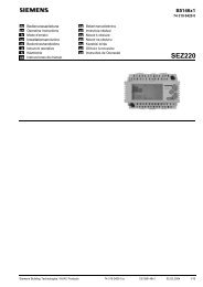
Wiring diagramsLine repeaterUse as a line repeater in sections exceeding 1200 m.<strong>PROFIBUS</strong>u1 (u2)PUR1.1UPUR1.1Uu2 (u1)<strong>PLR1.1</strong><strong>PROFIBUS</strong><strong>8923</strong>A02DecouplerWhen using a T-branch, it is always necessary to fit a <strong>PROFIBUS</strong> repeater fordecoupling. Looping of the <strong>PROFIBUS</strong> lines at both terminals (double T-branch) ispermitted.<strong>PROFIBUS</strong>u1 (u2)<strong>8923</strong>A01PUR1.1Uu2 (u1)<strong>PLR1.1</strong><strong>PROFIBUS</strong><strong>PLR1.1</strong> <strong>PROFIBUS</strong> repeaterPUR1.1U <strong>PROFIBUS</strong> terminatorat the repeater's connection terminalsu1 Connection for <strong>PROFIBUS</strong> section 1u2 Connection for <strong>PROFIBUS</strong> section 2NoteFor information on the maximum number of repeaters used with the same <strong>PROFIBUS</strong>,please refer to "Engineering notes".The repeater connections u1 and u2 for the two <strong>PROFIBUS</strong> sections are interchangeable.Dimensions126604,24 111 2183 049,523490354536 45ARG81.135EN 50022 - 32x7,5<strong>8923</strong>M01Dimensions in mm© 1999 Siemens Building Technologies Ltd.CM2N<strong>8923</strong>E / 10.1999Siemens Building Technologies6/6 Landis & Staefa Division