Intel Celeron™ Processor (PPGA) with the Intel 440LX AGPset
Intel Celeron™ Processor (PPGA) with the Intel 440LX AGPset
Intel Celeron™ Processor (PPGA) with the Intel 440LX AGPset

Create successful ePaper yourself
Turn your PDF publications into a flip-book with our unique Google optimized e-Paper software.
Information in this document is provided in connection <strong>with</strong> <strong>Intel</strong> products. No license, express or implied, by estoppel or o<strong>the</strong>rwise, to any intellectualproperty rights is granted by this document. Except as provided in <strong>Intel</strong>'s Terms and Conditions of Sale for such products, <strong>Intel</strong> assumes no liabilitywhatsoever, and <strong>Intel</strong> disclaims any express or implied warranty, relating to sale and/or use of <strong>Intel</strong> products including liability or warranties relating tofitness for a particular purpose, merchantability, or infringement of any patent, copyright or o<strong>the</strong>r intellectual property right. <strong>Intel</strong> products are notintended for use in medical, life saving, or life sustaining applications.<strong>Intel</strong> may make changes to specifications and product descriptions at any time, <strong>with</strong>out notice.Contact your local <strong>Intel</strong> sales office or your distributor to obtain <strong>the</strong> latest specifications and before placing your product order.The <strong>Intel</strong> ® Celeron <strong>Processor</strong>, <strong>Intel</strong> ® <strong>440LX</strong> <strong>AGPset</strong>, or <strong>Intel</strong> ® 440EX <strong>AGPset</strong> may contain design defects or errors which may cause <strong>the</strong> products todeviate from published specifications. Such errata are not covered by <strong>Intel</strong>’s warranty. Current characterized errata are available on request.I 2 C is a two-wire communications bus/protocol developed by Philips. SMBus is a subset of <strong>the</strong> I 2 C bus/protocol and was developed by <strong>Intel</strong>.Implementations of <strong>the</strong> I 2 C bus/protocol or <strong>the</strong> SMBus bus/protocol may require licenses from various entities, including Philips Electronics N.V. andNorth American Philips Corporation.Copies of documents which have an ordering number and are referenced in this document, or o<strong>the</strong>r <strong>Intel</strong> literature may be obtained by:calling 1-800-548-4725 orby visiting <strong>Intel</strong>'s website at http://www.intel.com.Copyright © <strong>Intel</strong> Corporation, 1998*Third-party brands and names are <strong>the</strong> property of <strong>the</strong>ir respective owners.<strong>Intel</strong> ® Celeron <strong>Processor</strong> (<strong>PPGA</strong>) Design Guide
Contents1 Introduction ................................................................................................................1-11.1 Overview .......................................................................................................1-11.2 Reference Documents And Information Sources..........................................1-11.3 Design Features............................................................................................1-21.3.1 <strong>Intel</strong> ® Celeron <strong>Processor</strong> (<strong>PPGA</strong>) ................................................1-21.3.2 <strong>Intel</strong> ® <strong>440LX</strong> and <strong>Intel</strong> ® 440EX <strong>AGPset</strong>s .........................................1-21.4 General Design Recommendations ..............................................................1-31.4.1 Voltage Definitions ...........................................................................1-31.4.2 General Design Recommendations .................................................1-31.5 Transitioning From an <strong>Intel</strong> ® Pentium ® II <strong>Processor</strong>/<strong>Intel</strong> ® <strong>440LX</strong> <strong>AGPset</strong> Design ........................................................................1-41.5.1 AGTL+ Termination..........................................................................1-41.5.2 Vref Inputs........................................................................................1-41.5.3 System Bus Clock............................................................................1-41.5.4 CMOS Compatibility <strong>with</strong> Future <strong>Processor</strong>s...................................1-41.5.5 <strong>Processor</strong> Core Voltage Decoupling................................................1-51.5.6 VID[4] ...............................................................................................1-51.5.7 Phase Lock Loop (PLL) Power ........................................................1-51.5.7.1 <strong>Processor</strong> PLL Filter Recommendation ..........................1-51.5.7.2 Topology .........................................................................1-51.5.7.3 Filter Specification ..........................................................1-61.5.7.4 Recommendation for <strong>Intel</strong> Platforms ..............................1-71.5.7.5 Custom Solutions............................................................1-81.5.8 Bus Frequency Selection .................................................................1-91.5.9 EDGCTRL........................................................................................1-91.5.10 VCOREDET .....................................................................................1-92 Mo<strong>the</strong>rboard Layout and Routing Guidelines ............................................................2-12.1 BGA Quadrant Assignment...........................................................................2-12.2 <strong>Intel</strong> ® Celeron <strong>Processor</strong> (<strong>PPGA</strong>) Signal Quadrants ................................2-22.3 Board Description .........................................................................................2-52.4 Routing Guidelines........................................................................................2-52.4.1 AGTL+ Description...........................................................................2-62.5 AGTL+ Layout Recommendations................................................................2-62.5.1 Network Topology and Conditions ...................................................2-62.5.2 Recommended Trace Lengths.........................................................2-62.5.2.1 Single <strong>Processor</strong> Simulation Results..............................2-72.5.3 Additional Guidelines .......................................................................2-72.5.3.1 For More Information on AGTL+.....................................2-72.5.4 Performance Requirements .............................................................2-72.5.5 Topology Definition ..........................................................................2-82.5.6 Pre-Layout Simulation (Sensitivity Analysis)....................................2-82.6 Post-Layout Simulation .................................................................................2-82.6.1 Crosstalk and <strong>the</strong> Multi-Bit Adjustment Factor.................................2-82.7 Timing Analysis.............................................................................................2-9<strong>Intel</strong> ® Celeron <strong>Processor</strong> (<strong>PPGA</strong>) Design Guideiii
2.8 82443LX Layout and Routing Guidelines ...................................................2-102.8.1 82443LX Clock Layout Recommendations....................................2-102.8.1.1 Clock Routing Spacing .................................................2-102.8.1.2 System Clock Layout....................................................2-112.8.1.3 O<strong>the</strong>r Busses................................................................2-113 Design Checklist ........................................................................................................3-13.1 Overview.......................................................................................................3-13.2 Pull-up and Pull-down Resistor Values.........................................................3-13.3 <strong>Processor</strong> Checklist ......................................................................................3-23.3.1 <strong>Intel</strong> ® Celeron <strong>Processor</strong>..............................................................3-23.3.2 GND & Power Pin Definition ............................................................3-43.3.3 <strong>Processor</strong> Clocks.............................................................................3-43.3.4 <strong>Processor</strong> Signals............................................................................3-53.3.5 <strong>Processor</strong> Decoupling Capacitors....................................................3-63.3.5.1 Core Voltage High Frequency Decoupling .....................3-63.4 Thermals / Cooling Solutions........................................................................3-73.4.1 Design Considerations:....................................................................3-73.5 Mechanicals..................................................................................................3-73.6 Electricals .....................................................................................................3-83.6.1 Design Considerations.....................................................................3-84 Debug Recommendations .........................................................................................4-14.1 Debug/Simulation Tools................................................................................4-14.1.1 Logic Analyzer Interface (LAI) .........................................................4-14.1.2 In-Target Probe (ITP).......................................................................4-14.1.3 I/O Buffer Models.............................................................................4-25 Third-Party Vendor Information .................................................................................5-15.1 Voltage Regulator Control Silicon.................................................................5-15.2 Clock Drivers ................................................................................................5-15.3 370-Pin Socket .............................................................................................5-1AReference Design Schematicsiv<strong>Intel</strong> ® Celeron <strong>Processor</strong> (<strong>PPGA</strong>) Design Guide
Figures1-1 Filter Topology ..............................................................................................1-51-2 Filter Specification.........................................................................................1-61-3 Using Discrete R ...........................................................................................1-71-4 No Discrete R................................................................................................1-81-5 Core Reference Model..................................................................................1-81-6 V COREDET Not Supported Using <strong>440LX</strong>/EX <strong>AGPset</strong>s...................................1-92-1 Major Signal Sections (82443LX Top View) .................................................2-12-2 <strong>Intel</strong> ® Celeron <strong>Processor</strong> (<strong>PPGA</strong>) Quadrants ...........................................2-22-3 Example ATX Placement for an <strong>Intel</strong> ® Celeron<strong>Processor</strong> (<strong>PPGA</strong>) / <strong>Intel</strong> ® <strong>440LX</strong> <strong>AGPset</strong> Design........................................2-32-4 Example NLX Placement for an <strong>Intel</strong> ® Celeron<strong>Processor</strong> (<strong>PPGA</strong>) / <strong>Intel</strong> ® <strong>440LX</strong> <strong>AGPset</strong> Design .......................................2-42-5 Four Layer Board Stack-up...........................................................................2-52-6 Recommended Topology..............................................................................2-62-7 Clock Trace Spacing Guidelines.................................................................2-102-8 Host Clock Topology...................................................................................2-113-1 Pull-up Resistor Example..............................................................................3-23-2 Capacitor Placement Study ..........................................................................3-6<strong>Intel</strong> ® Celeron <strong>Processor</strong> (<strong>PPGA</strong>) Design Guidev
Tables1-1 Inductor.........................................................................................................1-71-2 Capacitor ......................................................................................................1-71-3 Resistor.........................................................................................................1-72-1 Recommended Trace Lengths .....................................................................2-62-2 Model M Parameter Values For Interconnect SImulations ...........................2-72-3 Recommended 66 MHz System Flight Time Targets ...................................2-82-4 <strong>Intel</strong> ® Celeron <strong>Processor</strong> and <strong>Intel</strong> ® <strong>440LX</strong> <strong>AGPset</strong> SystemTiming Equations ..........................................................................................2-92-5 <strong>Intel</strong> ® Celeron <strong>Processor</strong> and <strong>Intel</strong> ® <strong>440LX</strong> <strong>AGPset</strong> SystemTiming Terms................................................................................................2-92-6 Recommended 66 MHz System Timing Parameters..................................2-103-1 AGTL+ Connectivity......................................................................................3-23-2 CMOS Connectivity ......................................................................................3-33-3 TAP Connectivity (optional 1 ).........................................................................3-33-4 Miscellaneous Connectivity ..........................................................................3-44-1 Third-Party LAIs & Logic Analyzer Software.................................................4-14-2 <strong>Intel</strong> In-Target Probe (ITP) Debuggers .........................................................4-24-3 Third-Party ITP-like Debuggers and Run Control Solutions .........................4-2vi<strong>Intel</strong> ® Celeron <strong>Processor</strong> (<strong>PPGA</strong>) Design Guide
Revision HistoryDate Revision Description1/99 -001 Initial Release.<strong>Intel</strong> ® Celeron <strong>Processor</strong> (<strong>PPGA</strong>) Design Guidevii
Introduction1
IntroductionIntroduction 1The <strong>Intel</strong> ® Celeron processor line includes processors that can be installed in a 370-pin socket.The <strong>Intel</strong> Celeron processor (<strong>PPGA</strong>) will also be offered as an <strong>Intel</strong> Boxed <strong>Processor</strong>, intended forsystem integrators who build systems from mo<strong>the</strong>rboards and o<strong>the</strong>r components. The intent of thisdocument is to organize any special design recommendations and concerns that exist for creatingan <strong>Intel</strong> Celeron processor (<strong>PPGA</strong>) / <strong>Intel</strong> ® <strong>440LX</strong>/EX <strong>AGPset</strong> based system. Likely design issueshave been identified and included here in a checklist format to alleviate problems during <strong>the</strong> designand debug phases. The information contained in this document should be used in conjunction <strong>with</strong><strong>the</strong> <strong>Intel</strong> ® Pentium ® II <strong>Processor</strong> / <strong>Intel</strong> ® <strong>440LX</strong> <strong>AGPset</strong> Design Guide. Exceptions to <strong>the</strong> <strong>Intel</strong> ®Pentium ® II <strong>Processor</strong> / <strong>Intel</strong> ® <strong>440LX</strong> <strong>AGPset</strong> Design Guide that are necessary for implementing an<strong>Intel</strong> Celeron processor (<strong>PPGA</strong>) / <strong>Intel</strong> ® <strong>440LX</strong> and <strong>Intel</strong> ® 440EX <strong>AGPset</strong> based systems arelisted in this document. For topics not covered in this document, refer to Pentium ® II <strong>Processor</strong>/<strong>Intel</strong> ® <strong>440LX</strong> <strong>AGPset</strong> Design Guide document.1.1 OverviewThis document contains information necessary for implementing an <strong>Intel</strong> Celeron processor(<strong>PPGA</strong>) / <strong>Intel</strong> <strong>440LX</strong> or a <strong>Intel</strong> 440EX platform design. Throughout <strong>the</strong> document references to<strong>the</strong> “processor” refer to <strong>the</strong> <strong>Intel</strong> Celeron processor (<strong>PPGA</strong>) or future processors that are designedto fit in <strong>the</strong> 370-pin socket. Additionally, design guidelines that are unchanged from <strong>the</strong>Pentium ® II <strong>Processor</strong> <strong>440LX</strong> <strong>AGPset</strong> Design Guide are not covered in this document.1.2 Reference Documents And Information SourcesDocument Name or Information Source<strong>Intel</strong> ® Celeron <strong>Processor</strong> Datasheet<strong>Intel</strong> ® 82443LX PCI <strong>AGPset</strong> Controller<strong>Intel</strong> ® 82371AB PCI-TO-ISA/IDE Xcelerator (PIIX4)Pentium ® II <strong>Processor</strong> <strong>440LX</strong> <strong>AGPset</strong> Design Guide<strong>Intel</strong> ® 82<strong>440LX</strong> <strong>AGPset</strong> Design Guide Update82443LX Application Notes82443LX Specification Update<strong>Intel</strong> ® Celeron <strong>Processor</strong> Specification UpdateAvailable From<strong>Intel</strong> Web Site<strong>Intel</strong> Web Site<strong>Intel</strong> Web Site<strong>Intel</strong> Web Site<strong>Intel</strong> Web Site<strong>Intel</strong> Field Sales Representative<strong>Intel</strong> Web Site<strong>Intel</strong> Web Site<strong>Intel</strong> ® Celeron <strong>Processor</strong> (<strong>PPGA</strong>) Design Guide 1-1
Introduction1.3 Design Features1.3.1 <strong>Intel</strong> ® Celeron <strong>Processor</strong> (<strong>PPGA</strong>)The <strong>Intel</strong> Celeron processor (<strong>PPGA</strong>) is <strong>the</strong> next addition to <strong>the</strong> <strong>Intel</strong> Celeron processor product line.The <strong>Intel</strong> Celeron processor (<strong>PPGA</strong>), like <strong>the</strong> <strong>Intel</strong> Celeron processor (S.E.P.P.), implements aDynamic Execution micro-architecture and executes MMX TM media technology instructions forenhanced media and communication performance. The <strong>Intel</strong> Celeron processor (<strong>PPGA</strong>) also uses<strong>the</strong> same multi-transaction system bus used in <strong>the</strong> <strong>Intel</strong> ® Pentium II processor. The <strong>Intel</strong> Celeronprocessor (<strong>PPGA</strong>) also supports multiple low-power states such as AutoHALT, Stop-Grant, Sleep,and Deep Sleep to conserve power during idle times.The <strong>Intel</strong> Celeron processor (<strong>PPGA</strong>) is based on <strong>the</strong> P6 core but is provided in a Plastic Pin GridArray (<strong>PPGA</strong>) package for use in low cost systems in <strong>the</strong> Basic PC market segment. The <strong>Intel</strong>Celeron processor (<strong>PPGA</strong>) utilizes <strong>the</strong> AGTL+ system bus used by <strong>the</strong> Pentium II processor <strong>with</strong>support limited to single processor-based systems. Support for multi-processor-based systems isnot provided <strong>with</strong> <strong>the</strong> <strong>Intel</strong> Celeron processor (<strong>PPGA</strong>). Pentium II processors should be used formulti-processor system designs. The <strong>Intel</strong> Celeron processor (<strong>PPGA</strong>) includes an integrated128 KB second level cache <strong>with</strong> a separate 16 KB instruction and 16 KB data level one caches. Thesecond level cache is capable of caching 4 GB of system memory address space.To enable cost reduction at both <strong>the</strong> processor and system level, <strong>the</strong> <strong>Intel</strong> Celeron processor(<strong>PPGA</strong>) utilizes a packaging technology, known as <strong>the</strong> Plastic Pin Grid Array (<strong>PPGA</strong>). Thispackaging technology is similar to <strong>the</strong> mature Pentium processor package.1.3.2 <strong>Intel</strong> ® <strong>440LX</strong> and <strong>Intel</strong> ® 440EX <strong>AGPset</strong>sThis information is being provided to <strong>Intel</strong> customers to begin developing a design <strong>with</strong> <strong>the</strong>82443LX. The 82443LX, 82443EX are Basic PC solutions for an <strong>Intel</strong> Celeron processor-basedplatform.The 82443LX has <strong>the</strong> following features:• Maximum of 4 DIMM sockets (512 MB SDRAM memory, 1 GB EDO memory)• Maximum of 5 PCI slots (5 PREQx#/PGNTx# pairs support 5 PCI masters. PHOLD# andPHLDA# continue to support <strong>the</strong> PIIX4E as ano<strong>the</strong>r bus master. There is support for a total of6 PCI masters including <strong>the</strong> PIIX4E. Five PCI slots means 5 bus masters using <strong>the</strong> available5 PREQx#/PGNTx# pairs. The physical location of <strong>the</strong>se 5 PCI bus masters may be in cardsinserted in <strong>the</strong> 5 PCI slots, or in cards inserted in 4 PCI slots toge<strong>the</strong>r <strong>with</strong> one PCI bus masterdown on <strong>the</strong> mo<strong>the</strong>rboard, or in cards inserted in 3 PCI slots toge<strong>the</strong>r <strong>with</strong> two PCI mastersdown on <strong>the</strong> mo<strong>the</strong>rboard, etc.)• 66 MHz-only system bus/DRAM bus frequency1-2 <strong>Intel</strong> ® Celeron <strong>Processor</strong> (<strong>PPGA</strong>) Design Guide
IntroductionThe 82443EX has <strong>the</strong> following features:• Maximum of 2 DIMM sockets (256 MB memory, SDRAM or EDO)• Maximum of 3 PCI slots (3 PREQx#/PGNTx# pairs support 3 PCI masters. PHOLD# andPHLDA# continue to support <strong>the</strong> PIIX4E as ano<strong>the</strong>r bus master. There is support for a total of4 PCI masters including <strong>the</strong> PIIX4E. 3 PCI slots means 3 bus masters using <strong>the</strong> available 3PREQx#/PGNTx# pairs. The physical location of <strong>the</strong>se 3 PCI bus masters may be in cardsinserted in <strong>the</strong> 3 PCI slots, or in cards inserted in 2 PCI slots toge<strong>the</strong>r <strong>with</strong> one PCI bus masterdown on <strong>the</strong> mo<strong>the</strong>rboard, or in cards inserted in 1 PCI slots toge<strong>the</strong>r <strong>with</strong> two PCI mastersdown on <strong>the</strong> mo<strong>the</strong>rboard, etc.)• No system memory ECC• Single processor support only (no support for IOAPIC)• 66 MHz-only system bus/DRAM bus frequencyNote:The designation <strong>Intel</strong> ® <strong>440LX</strong> <strong>AGPset</strong> (82443LX) will be used throughout <strong>the</strong> remainder of thisdocument and will apply to both <strong>the</strong> <strong>Intel</strong> ® <strong>440LX</strong> <strong>AGPset</strong> and <strong>Intel</strong> ® 440EX <strong>AGPset</strong>, unlesso<strong>the</strong>rwise noted.1.4 General Design Recommendations1.4.1 Voltage DefinitionsFor <strong>the</strong> purposes of this document <strong>the</strong> following nominal voltage definitions are used:Vcc 5.0VVcc 3.3 3.3VVcc CORE Voltage is dependent on <strong>the</strong> four bit VID settingVcc 2.5 2.5VVcc CMOS 2.5VV TT 1.5VV REF 1.0VAGPV REF 1.32V1.4.2 General Design Recommendations1. <strong>Intel</strong> recommends using a widely available, programmable Voltage Regulator Module (VRM)installed in a VRM header or an onboard programmable voltage regulator. Please see <strong>the</strong> VRM8.2 DC-DC Converter Design Guidelines.2. Mo<strong>the</strong>rboard designs targeted for system integrators should design to <strong>the</strong> boxed processorelectrical, mechanical and <strong>the</strong>rmal specifications provided in <strong>the</strong> boxed processor section of<strong>the</strong> <strong>Intel</strong> ® Celeron <strong>Processor</strong> Datasheet, most notably <strong>the</strong> required fan power header andfan/heatsink physical clearance on <strong>the</strong> mo<strong>the</strong>rboard.<strong>Intel</strong> ® Celeron <strong>Processor</strong> (<strong>PPGA</strong>) Design Guide 1-3
Introduction1.5 Transitioning From an <strong>Intel</strong> ® Pentium ® II <strong>Processor</strong>/<strong>Intel</strong> ® <strong>440LX</strong> <strong>AGPset</strong> Design1.5.1 AGTL+ TerminationTermination is no longer provided on <strong>the</strong> processor and must be implemented on <strong>the</strong> system board.In addition, high frequency Vtt decoupling is also required on <strong>the</strong> system board. <strong>Intel</strong> recommendsone 0.1 uF capacitor in <strong>the</strong> 0603 package for every two resistor packs.1.5.2 Vref InputsVref (2/3 Vtt) must be supplied to <strong>the</strong> processor to each of <strong>the</strong> eight V REF inputs. <strong>Intel</strong> recommendsusing one 75 ±1% and 150 ±1% ohm resistor divider of <strong>the</strong> Vtt supply to generate V REF . <strong>Intel</strong> alsorecommends placing four 0.1 uF capacitors, in <strong>the</strong> 0603 package, <strong>with</strong>in 500 mils of <strong>the</strong>processor’s V REF pins.1.5.3 System Bus ClockDue to <strong>the</strong> change in system bus trace lengths in <strong>the</strong> <strong>PPGA</strong> package, chipset and processor clocksmust be ganged to minimize pin to pin clock skew. Implementation details are provided in <strong>the</strong>AGTL+ section of this document.It is also recommended that a capacitor site be placed near <strong>the</strong> processor BCLK input to allow <strong>the</strong>clock skew to be minimized through tuning, by changing <strong>the</strong> value at <strong>the</strong> capacitor site, tocompensate for <strong>the</strong> actual mo<strong>the</strong>rboard trace lengths.1.5.4 CMOS Compatibility <strong>with</strong> Future <strong>Processor</strong>sAll processor CMOS outputs are open drain and require a pullup to drive to external logic. The<strong>Intel</strong> Celeron processor (<strong>PPGA</strong>) is 2.5 Volt compatible. The <strong>Intel</strong> <strong>440LX</strong> <strong>AGPset</strong> and <strong>the</strong> <strong>Intel</strong>440EX <strong>AGPset</strong> do not support future processors based on a 1.5V core.<strong>Intel</strong> has defined three new pins for <strong>the</strong> <strong>Intel</strong> Celeron processor (<strong>PPGA</strong>):• VCC 2.5 : This pin should be connected to <strong>the</strong> system’s 2.5V supply.• VCC 1.5 : This pin should be left open. (not supported).• VCC CMOS : This pin should be used as <strong>the</strong> system CMOS pullup voltage. A 0.1 uF decouplingcapacitor is recommended.For an <strong>Intel</strong> Celeron processor (<strong>PPGA</strong>), VCC CMOS will be directly tied to <strong>the</strong> VCC 2.5 pin, <strong>the</strong>rebyproviding 2.5V to system CMOS pullups. As a design option, <strong>the</strong> 2.5V supply may be directly usedand <strong>the</strong>se three pins may be left as no-connects.These pins have been defined to permit a current of 500 mA maximum.1-4 <strong>Intel</strong> ® Celeron <strong>Processor</strong> (<strong>PPGA</strong>) Design Guide
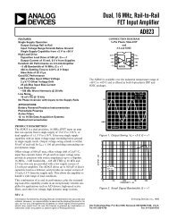
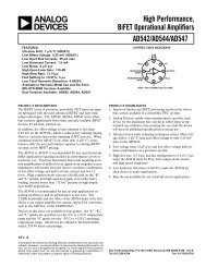
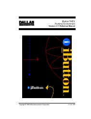
Introduction1.5.5 <strong>Processor</strong> Core Voltage Decoupling1.5.6 VID[4]High frequency decoupling for <strong>the</strong> processor core voltage is no longer provided on <strong>the</strong> processor asin previous generation processors. As a result, <strong>the</strong> system board must implement <strong>the</strong>se capacitors.<strong>Intel</strong> recommends ten or more 4.7 uF capacitors in <strong>the</strong> 1206 package (ceramic X5R or bettermaterial) as well as nineteen or more 1.0 uF capacitors in <strong>the</strong> 0805 package to be placed <strong>with</strong>in <strong>the</strong>socket cavity. Placement of <strong>the</strong> capacitors should be such that overall inductance between Vcc/Vsspower pins is minimized. Meeting <strong>the</strong>se guidelines will insure system compatibility <strong>with</strong> future<strong>PPGA</strong> <strong>Intel</strong> ® Celeron processors. Implementation details are provided later in this document.VID[4] is not provided on <strong>the</strong> processor. Therefore, according to <strong>the</strong> VRM 8.2 DC-DC ConverterGuidelines, VID[4] must be connected to ground on <strong>the</strong> system board to provide <strong>the</strong> correctVID[3:0] for 1.3V to 2.05V Voltage ID Encoding.1.5.7 Phase Lock Loop (PLL) Power1.5.7.1 <strong>Processor</strong> PLL Filter Recommendation1.5.7.2 TopologyAll <strong>Intel</strong> Celeron processors have internal PLL clock generators which are analog and require quietpower supplies for minimum jitter.The general desired topology is shown in Figure 1-1. Not shown are parasitic routing and localdecoupling capacitors. Excluded from <strong>the</strong> external circuitry are parasitics associated <strong>with</strong> eachcomponent.Figure 1-1. Filter TopologyVCC CORERLPLL1CPLL370-PinSocketPLL2VSS = 0Vv004<strong>Intel</strong> ® Celeron <strong>Processor</strong> (<strong>PPGA</strong>) Design Guide 1-5
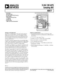
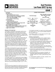
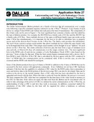
Introduction1.5.7.3 Filter SpecificationThe function of <strong>the</strong> filter is to protect <strong>the</strong> PLL from external noise through low-pass attenuation. Ingeneral, <strong>the</strong> low-pass description forms an adequate description for <strong>the</strong> filter.The low-pass specification, <strong>with</strong> input at VCC CORE and output measured across <strong>the</strong> capacitor, is asfollows:< 0.2 dB gain in pass band< 0.5 dB attenuation in pass band (see DC drop in next set of requirements)> 34 dB attenuation from 1 MHz to 66 MHz> 28 dB attenuation from 66 MHz to core frequencyThe filter specification is graphically shown in Figure 1-2.Figure 1-2. Filter Specification0.2dB0dBx dB-28dB-34dBDC1Hzfpeak1 MHz 66 MHz fcorepassbandx = 20.log[(Vcc-60mV)/Vcc]NOTES:1. Diagram not to scale.2. No specification for frequencies beyond fcore.3. fpeak, if it exists, it should be less than 0.05 MHz.high frequencybandfilt 1 dO<strong>the</strong>r requirements:• Filter should support DC current > 30 mA.• Shielded type inductor to minimize magnetic pickup.• DC voltage drop from VCC to PLL1 should be < 60mV, which in practice implies seriesR < 2W; also means pass band (from DC to 1Hz) attenuation < 0.5dB forVCC = 1.1V, and < 0.35dB for VCC = 1.5V.1-6 <strong>Intel</strong> ® Celeron <strong>Processor</strong> (<strong>PPGA</strong>) Design Guide
Introduction1.5.7.4 Recommendation for <strong>Intel</strong> PlatformsTable 1-1. InductorThe following tables are examples of components that meet <strong>Intel</strong>’s recommendations, whenconfigured in <strong>the</strong> topology presented in Figure 1-1.Part Number Value Tol SRF Rated I DCRTDK MLF2012A4R7KT 4.7uH 10% 35MHz 30mA 0.56Ω (1W max)Murata LQG21N4R7K00T1 4.7uH 10% 47MHz 30mA 0.7Ω (±50%)Murata LQG21C4R7N00 4.7uH 30% 35MHz 30mA 0.3Ω maxTable 1-2. CapacitorPart Number Value Tolerance ESL ESRKemet T495D336M016AS 33uF 20% 2.5nH 0.225ΩAVX TPSD336M020S0200 33uF 20% TBD 0.2ΩTable 1-3. ResistorValue Tolerance Power Note1Ω 10% 1/16WResistor may be implemented <strong>with</strong> trace resistance, in whichdiscrete R is not neededTo satisfy damping requirements, total series resistance in <strong>the</strong> filter (from VCC CORE to <strong>the</strong> topplate of <strong>the</strong> capacitor) must be at least 0.35Ω. This resistor can be in <strong>the</strong> form of a discretecomponent, or routing, or both. For example, if <strong>the</strong> picked inductor has a minimum DCR of 0.25Ω,<strong>the</strong>n a routing resistance of at least 0.10Ω is required. Be careful not to exceed <strong>the</strong> maximumresistance rule (2Ω). For example, if using discrete R1, <strong>the</strong> maximum DCR of <strong>the</strong> L should be lessthan 2.0 - 1.1 = 0.9Ω, which precludes using some inductors.O<strong>the</strong>r routing requirements:• C should be close to PLL1 and PLL2 pins, < 0.1Ω per route. These routes do not count towards<strong>the</strong> minimum damping R requirement.• PLL2 route should be parallel and next to PLL1 route (minimize loop area).• L should be close to C; any routing resistance should be inserted between VCC CORE and L.• Any discrete R should be inserted between VCC CORE and L.Figure 1-3. Using Discrete RVCC CORERDiscrete ResistorL
IntroductionFigure 1-4. No Discrete RVCC CORETrace ResistanceLC
Introduction1.5.8 Bus Frequency SelectionThe BSEL pin on <strong>the</strong> <strong>Intel</strong> Celeron processor (<strong>PPGA</strong>) is used to select <strong>the</strong> system bus frequency.BSEL is Low for 66 MHz. BSEL should be pulled to ground on <strong>the</strong> mo<strong>the</strong>rboard.1.5.9 EDGCTRLA new pin that is required for correct operation of <strong>the</strong> processor, EDGCTRL, requires 51 ohm 5%pullup to Vcc CORE .1.5.10 V COREDETThe <strong>Intel</strong> <strong>440LX</strong>/EX <strong>AGPset</strong>s do not support 0.18 micron processors. The V COREDET pin can beused by external mo<strong>the</strong>rboard logic to prevent <strong>the</strong> platform from operating if a 0.18u processor isinstalled. The V COREDET pin is tied to Vss on <strong>the</strong> package. Connect this pin to <strong>the</strong> externalmo<strong>the</strong>rboard logic. A logic low can gate <strong>the</strong> platform from powering up. For <strong>Intel</strong> ® Celeronprocessors based on <strong>the</strong> 0.25 micron process, <strong>the</strong> V COREDET pin is a no-connect (floating) on <strong>the</strong>package. Refer to Figure 1-6 as an example.Figure 1-6. V COREDET Not Supported Using <strong>440LX</strong>/EX <strong>AGPset</strong>sVcc3<strong>Processor</strong>E21220-450 Ohms82443LX82443EXSystemShutdownLogic<strong>Intel</strong> ® Celeron <strong>Processor</strong> (<strong>PPGA</strong>) Design Guide 1-9
Introduction1-10 <strong>Intel</strong> ® Celeron <strong>Processor</strong> (<strong>PPGA</strong>) Design Guide
Mo<strong>the</strong>rboard Design2
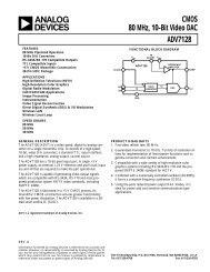
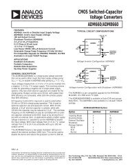
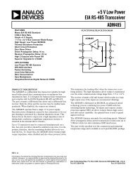
Mo<strong>the</strong>rboard Layout and Routing GuidelinesMo<strong>the</strong>rboard Layout and RoutingGuidelines 2This section describes layout and routing recommendations to insure a robust design. Follow <strong>the</strong>seguidelines as closely as possible. Any deviations from <strong>the</strong> guidelines listed here should besimulated to insure adequate margin is still maintained in <strong>the</strong> design.2.1 BGA Quadrant Assignment<strong>Intel</strong> assigned pins on <strong>the</strong> 82443LX to simplify routing and keep board fab costs down, bypermitting a mo<strong>the</strong>rboard to be routed in 4-layers. Figure 2-1 shows <strong>the</strong> 4 signal quadrants of <strong>the</strong>82443LX. The component placement on <strong>the</strong> mo<strong>the</strong>rboard should be done <strong>with</strong> this general flow inmind. This simplifies routing and minimizes <strong>the</strong> number of signals which must cross. Theindividual signals <strong>with</strong>in <strong>the</strong> respective groups have also been optimized in order to be routed usingonly 2 PCB layers.The 82443LX datasheet contains a complete list of signals and ball assignments.Figure 2-1. Major Signal Sections (82443LX Top View)Pin #1CornerAGPQuadrantABCDEFGHJKLMNPRTUVWYAAABACADAEAF1PCIQuadrant2 3 4 5 678 9 10 11 12 13 14 15 16 17 18 19 20 21 22 23 24 25 26AGTL+QuadrantDRAMQuadrant<strong>Intel</strong> ® Celeron <strong>Processor</strong> (<strong>PPGA</strong>) Design Guide 2-1
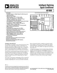
Mo<strong>the</strong>rboard Layout and Routing Guidelines2.2 <strong>Intel</strong> ® Celeron <strong>Processor</strong> (<strong>PPGA</strong>) SignalQuadrantsFigure 2-2. <strong>Intel</strong> ® Celeron <strong>Processor</strong> (<strong>PPGA</strong>) Quadrants12 4 6 83 5 710 12 14 16 18 20 22 24 26 28 30 32 34 369 11 13 15 17 19 21 23 25 27 29 31 33 35 37AGTL+ SignalsANAMALAKAJAHAGAFAEADACABAAZYXWVUTSRQPNMLKJHGFEDCBAPin Side ViewANAMALAKAJAHAGAFAEADACABAAZYXWVUTSRQPNMLKJHGFEDCBACMOSVCC CMOSPLL1, PLL2Interrupts12 4 6 83 5 710 12 14 16 18 20 22 24 26 28 30 32 34 369 11 13 15 17 19 21 23 25 27 29 31 33 35 37Figure 2-2 indicates <strong>the</strong> signal quadrants for <strong>the</strong> <strong>Intel</strong> Celeron processor (<strong>PPGA</strong>). Thesequadrants were defined to facilitate layout and placement and show <strong>the</strong> proposed componentplacement for an <strong>Intel</strong> Celeron processor (<strong>PPGA</strong>) for both ATX and NLX form factor designs.2-2 <strong>Intel</strong> ® Celeron <strong>Processor</strong> (<strong>PPGA</strong>) Design Guide
Mo<strong>the</strong>rboard Layout and Routing GuidelinesATX Form Factor:1. The ATX placement and layout below is recommended for an <strong>Intel</strong> ® Celeron processor(<strong>PPGA</strong>) / <strong>Intel</strong> ® <strong>440LX</strong> <strong>AGPset</strong> system design.2. The example placement below shows 4 PCI slots, 2 ISA slots, 2 DIMM sockets, and one AGPconnector.3. For an ATX form factor design, <strong>the</strong> AGP compliant graphics device can be ei<strong>the</strong>r on <strong>the</strong>mo<strong>the</strong>rboard (device down option), or on an AGP connector (up option).4. The trace length limitation between critical connections will be addressed later in thisdocument.5. Figure 2-3 is for reference only and <strong>the</strong> trade-off between <strong>the</strong> number of PCI and ISA slots,number of DIMM sockets, and o<strong>the</strong>r mo<strong>the</strong>rboard peripherals needs to be evaluated for eachdesign.Figure 2-3. Example ATX Placement for an <strong>Intel</strong> ® Celeron <strong>Processor</strong> (<strong>PPGA</strong>) / <strong>Intel</strong> ® <strong>440LX</strong><strong>AGPset</strong> DesignI/O PortsPCI0AGP/PCI1A1 Plug370-Pin SocketPin A1PCI InterfaceAGP Interface82443LXHost InterfaceSDRAM InterfaceCK3DSDRAM DIMMsPIIX4EIDE 0/1<strong>Intel</strong> ® Celeron <strong>Processor</strong> (<strong>PPGA</strong>) Design Guide 2-3
Mo<strong>the</strong>rboard Layout and Routing GuidelinesNLX Form Factor:The NLX placement and layout below is recommended for a <strong>Intel</strong> ® Celeron processor (<strong>PPGA</strong>) /<strong>Intel</strong> ® <strong>440LX</strong> <strong>AGPset</strong> system design.1. The example placement below shows 2 DIMM sockets, and an AGP compliant device down on<strong>the</strong> mo<strong>the</strong>rboard.2. For an NLX form factor design, <strong>the</strong> AGP compliant graphics device may readily be integratedon <strong>the</strong> mo<strong>the</strong>rboard (device down option).3. The trace length limitation between critical connections will be addressed later in thisdocument.4. Figure 2-4 is for reference only and <strong>the</strong> trade-off between <strong>the</strong> number of DIMM sockets, ando<strong>the</strong>r mo<strong>the</strong>rboard peripherals needs to be evaluated for each design.Figure 2-4. Example NLX Placement for an <strong>Intel</strong> ® Celeron <strong>Processor</strong> (<strong>PPGA</strong>) / <strong>Intel</strong> ® <strong>440LX</strong><strong>AGPset</strong> DesignSDRAM DIMMsCK3DAGPSDRAMInterfaceHost Interface82443LXAGP InterfacePCI InterfaceI/O Ports370-Pin SocketPIIX4EPCI0/ISA Riser2-4 <strong>Intel</strong> ® Celeron <strong>Processor</strong> (<strong>PPGA</strong>) Design Guide
Mo<strong>the</strong>rboard Layout and Routing Guidelines2.3 Board DescriptionA 4 layer stack-up arrangement is recommended for <strong>the</strong> system board. The stack up of <strong>the</strong> board isshown in Figure 2-5. The impedance of all <strong>the</strong> signal layers are to be between 55 and 75 ohms.Lower trace impedance will reduce signal edge rates, over & undershoot, and have less cross-talkthan higher trace impedance. Higher trace impedance will increase edge rates and may slightlydecrease signal flight times.Figure 2-5. Four Layer Board Stack-upZ = 65 ohmsZ = 65 ohms5 mils47 mils5 milsPrimary Signal Layer (1/2 oz. cu.)PREPREGGround Plane (1 oz. cu.)COREPower Plane (1 oz. cu)PREPREGSecondary Signal Layer (1/2 oz. cu)Total board thickness = 62.6milsNote that <strong>the</strong> top and bottom routing layers specify 1/2 oz. cu. However, by <strong>the</strong> time <strong>the</strong> board isplated, <strong>the</strong> traces will be about 1 oz. Check <strong>with</strong> your fab vendor on <strong>the</strong> exact value and insure thatany signal simulation accounts for this.Note:A thicker core may help reduce board warpage issues.Additional guidelines on board stackup, placement and layout include:• Single ended termination is recommended for AGTL+ signals. One termination resistor ispresent on <strong>the</strong> system board. The trace lengths should be controlled to 2.0” minimum and 5.5”maximum.• The termination resistors on <strong>the</strong> AGTL+ bus should be 56 ohms ±5%.• The board impedance (Z) should be between 55 and 75 ohms (65 ohms ±15%)• FR-4 material should be used for <strong>the</strong> board fabrication.• The ground plane should not be split on <strong>the</strong> ground plane layer. If a signal must be routed for ashort distance on a power plane, <strong>the</strong>n it should be routed on a VCC plane, not <strong>the</strong> groundplane.• Keep vias for decoupling capacitors as close to <strong>the</strong> capacitor pads as possible.2.4 Routing GuidelinesThis section lists guidelines to be followed when routing <strong>the</strong> signal traces for <strong>the</strong> board design. Theorder that signals are routed first and last will vary from designer to designer. Some designersprefer routing all of <strong>the</strong> clock signals first, while o<strong>the</strong>rs prefer routing all of <strong>the</strong> high speed bussignals first. Ei<strong>the</strong>r order can be used, as long as <strong>the</strong> guidelines listed here are followed. If <strong>the</strong>guidelines listed here are not followed, it is important that your design is simulated, especially on<strong>the</strong> AGTL+ signals. Even when <strong>the</strong> guidelines are followed, it is still a good idea to simulate asmany signals as possible for proper signal integrity, flight time and cross talk.<strong>Intel</strong> ® Celeron <strong>Processor</strong> (<strong>PPGA</strong>) Design Guide 2-5
Mo<strong>the</strong>rboard Layout and Routing Guidelines2.4.1 AGTL+ DescriptionAGTL+ is <strong>the</strong> electrical bus technology used for <strong>the</strong> <strong>Intel</strong> ® Celeron processor and <strong>Intel</strong> ®Pentium ® II processor host buses. AGTL+ is a low output swing, incident wave switching, opendrainbus <strong>with</strong> external pull-up resistors that provide both <strong>the</strong> high logic level and termination at <strong>the</strong>end of <strong>the</strong> bus. The AGTL+ specification is contained in <strong>the</strong> <strong>Intel</strong> ® P6 Family <strong>Processor</strong>Developer’s Manual.2.5 AGTL+ Layout RecommendationsThis section contains <strong>the</strong> layout recommendations for <strong>the</strong> AGTL+ signals. The layoutrecommendations are derived from pre-layout simulations that <strong>Intel</strong> has performed.2.5.1 Network Topology and ConditionsThe recommended topology for single processor systems is shown in Figure 2-6. A terminationresistor is placed on <strong>the</strong> system board. The recommended value for <strong>the</strong> termination resistor is56Ω ± 5%.Figure 2-6. Recommended TopologyV TTL2R TT370-PinSocketL1<strong>Intel</strong> ®<strong>440LX</strong><strong>AGPset</strong>2.5.2 Recommended Trace LengthsTrace length recommendations are summarized Table 2-1. The recommended lengths are derivedfrom <strong>the</strong> parametric sweeps and Monte Carlo analysis.Table 2-1. Recommended Trace LengthsTrace Minimum Length Maximum LengthL1 2.0” 5.5”L2 0.5” 2.0”<strong>Intel</strong> recommends running analog simulations using <strong>the</strong> available I/O buffer models toge<strong>the</strong>r <strong>with</strong>layout information extracted from your specific design. Simulation will confirm that <strong>the</strong> designadheres to <strong>the</strong> guidelines.2-6 <strong>Intel</strong> ® Celeron <strong>Processor</strong> (<strong>PPGA</strong>) Design Guide
Mo<strong>the</strong>rboard Layout and Routing Guidelines2.5.2.1 Single <strong>Processor</strong> Simulation ResultsParametric SweepsThe values for interconnect parameter values that were used in all parametric sweeps aresummarized in Table 2-2.Table 2-2. Model M Parameter Values For Interconnect SImulationsComponent Parameter Fast Typical Slow<strong>PPGA</strong>Z 0 [Ω]S 0 [ns/ft]74.751.6 (µstrip)1.8 (stripline & embµstrip)65.001.8 (µstrip)2.0 (stripline & embµstrip)55.252.0 (µstrip)2.2 (stripline & embµstrip)Mo<strong>the</strong>rBoardZ 0 [Ω]S 0 [ns/ft]74.751.865.002.055.252.2ConnectorZ 0 [Ω]T d [ps]80306510050120Termination R TT [Ω] 56 - 5% 56 56 + 5%V TT [V] 1.5 + 9% 1.5 1.5 - 9%Note:For simulation purposes, <strong>the</strong> socket connector can be modelled as a transmission line. The length of<strong>the</strong> line and <strong>the</strong> propagation speed must be selected such that <strong>the</strong>y give a total delay of 120 ps in <strong>the</strong>slow case and 30 ps in <strong>the</strong> fast case.2.5.3 Additional Guidelines2.5.3.1 For More Information on AGTL+The general rules for minimizing <strong>the</strong> impact of crosstalk and o<strong>the</strong>r practical considerations in <strong>the</strong>design of a high speed AGTL+ bus are discussed in <strong>the</strong> Pentium ® II <strong>Processor</strong>/<strong>440LX</strong> <strong>AGPset</strong>Design Guide document.2.5.4 Performance RequirementsPrior to performing interconnect simulations, establish <strong>the</strong> minimum and maximum flight timerequirements. Setup and hold requirements determine <strong>the</strong> flight time bounds for <strong>the</strong> system bus.The bus contains two paths which must be considered:• <strong>the</strong> processor driving an <strong>AGPset</strong> component• <strong>the</strong> <strong>AGPset</strong> component driving a processorTable 2-3 provides recommended flight time specifications. Flight times are measured at <strong>the</strong>processor pins.<strong>Intel</strong> ® Celeron <strong>Processor</strong> (<strong>PPGA</strong>) Design Guide 2-7
Mo<strong>the</strong>rboard Layout and Routing GuidelinesTable 2-3. Recommended 66 MHz System Flight Time TargetsDriver Receiver T flight,min [ns] T flight,max [ns]<strong>Processor</strong> <strong>AGPset</strong> 0.10 2.10<strong>AGPset</strong> <strong>Processor</strong> 0.0 4.052.5.5 Topology DefinitionAs described in Section 2.5.1, AGTL+ is sensitive to transmission line stubs, which can result inringing on <strong>the</strong> rising edge caused by <strong>the</strong> high impedance of <strong>the</strong> output buffer in <strong>the</strong> high state.AGTL+ signals should be connected in a daisy chain, keeping transmission line stubs to <strong>the</strong>processor under 2.0 inches.2.5.6 Pre-Layout Simulation (Sensitivity Analysis)After an initial timing analysis has been completed, simulations should be performed to determine<strong>the</strong> bounds on system layout. AGTL+ interconnect simulations using transmission line models arerecommended to determine signal quality and flight times for proposed layouts. Recommendedparameter values shown in Table 2-2 should be used for simulation. The recommended values inTable 2-2 may be replaced if your supplier’s specific capabilities are known. The corner valuesshould comprehend <strong>the</strong> full range of manufacturing variation. The <strong>Intel</strong> ® Celeron processor(<strong>PPGA</strong>) models include <strong>the</strong> I/O buffer models, core package parasitics, package trace length,impedance and velocity. <strong>Intel</strong> ® <strong>440LX</strong> APGset models are available and include <strong>the</strong> I/O buffersand package traces. Termination resistors should be controlled to <strong>with</strong>in ± 5%.2.6 Post-Layout SimulationFollowing layout, extract <strong>the</strong> traces and run simulations to verify that <strong>the</strong> layout meets timing andnoise requirements. A small amount of trace “tuning” may be required, but experience at <strong>Intel</strong> hasshown that sensitivity analysis dramatically reduces <strong>the</strong> amount of tuning required.The post layout simulations should take into account <strong>the</strong> expected variation for all interconnectparameters. For timing simulations, use a V REF of 2/3 V TT ± 2% for both <strong>the</strong> processor and <strong>Intel</strong> ®<strong>440LX</strong> <strong>AGPset</strong> components. Flight times measured from <strong>the</strong> processor pins to o<strong>the</strong>r systemcomponents use <strong>the</strong> normal flight time method.2.6.1 Crosstalk and <strong>the</strong> Multi-Bit Adjustment FactorCoupled lines should be included in <strong>the</strong> post-layout simulations. The flight times listed in Table 2-3apply to single bit simulations only. They do not include an allowance for crosstalk. Crosstalkeffects are accounted for separately, as part of <strong>the</strong> multi-bit timing adjustment factor, T adj , that isdefined in Table 2-5. The recommended timing budget includes 300 ps for <strong>the</strong> adjustment factor.Use caution in applying T adj to coupled simulations. This adjustment factor encompasses o<strong>the</strong>reffects besides board coupling, such as processor and package crosstalk, and ground returninductances. In general, <strong>the</strong> additional delay introduced by coupled simulations should be less than300 ps.2-8 <strong>Intel</strong> ® Celeron <strong>Processor</strong> (<strong>PPGA</strong>) Design Guide
Mo<strong>the</strong>rboard Layout and Routing Guidelines2.7 Timing AnalysisTo determine <strong>the</strong> available flight time window, perform an initial timing analysis. Analysis of setupand hold conditions will determine <strong>the</strong> minimum and maximum flight time bounds for <strong>the</strong> systembus. Use <strong>the</strong> following equations to establish <strong>the</strong> system flight time limits.Table 2-4. <strong>Intel</strong> ® Celeron <strong>Processor</strong> and <strong>Intel</strong> ® <strong>440LX</strong> <strong>AGPset</strong> System Timing EquationsDriver Receiver Equationprocessor<strong>AGPset</strong>T ≥T − T + T + T + Tflight,min hold co,min skew, CLK skew, PCB skew,SKTT ≤T −T −T −T −T −T −T −Tflight ,max cycle co,max su skew, CLK skew, PCB skew,SKT jit adj<strong>AGPset</strong>processorT ≥T − T + T + T + Tflight,min hold co,min skew, CLK skew, PCB skew,SKTT ≤T −T −T −T −T −T −T −Tflight ,max cycle co,max su skew, CLK skew, PCB skew,SKT jit adjThe terms used in <strong>the</strong> equations are described below.Table 2-5. <strong>Intel</strong> ® Celeron <strong>Processor</strong> and <strong>Intel</strong> ® <strong>440LX</strong> <strong>AGPset</strong> System Timing TermsTermT cycleT flight,minT flight,maxT co,maxT co,minT suT hT skew,CLKT skew,PCBT skew,SKTT jitT adjDescriptionSystem cycle time, defined as <strong>the</strong> reciprocal of <strong>the</strong> frequencyMinimum system flight time.Maximum system flight time.Maximum driver delay from input clock to output data.Minimum driver delay from input clock to output data.Minimum setup time. Defined as <strong>the</strong> time for which <strong>the</strong> input data must be valid prior to <strong>the</strong>input clock.Minimum hold time. Defined as <strong>the</strong> time for which <strong>the</strong> input data must remain valid after <strong>the</strong>input clock.Clock generator skew. Defined as <strong>the</strong> maximum delay variation between output clock signalsfrom <strong>the</strong> system clock generator.PCB skew. Defined as <strong>the</strong> maximum delay variation between clock signals due to systemboard variation and <strong>Intel</strong> ® <strong>440LX</strong> <strong>AGPset</strong> loading variation.Skew due to delay in <strong>the</strong> 370-pin socket.Clock jitter. Defined as <strong>the</strong> maximum edge to edge variation in a given clock signal.Multi-bit timing adjustment factor. This term accounts for <strong>the</strong> additional delay that occurs in<strong>the</strong> network when multiple data bits switch in <strong>the</strong> same cycle. The adjustment factor includessuch mechanisms as package and PCB crosstalk, high inductance current return paths, andsimultaneous switching noise.Component timings for <strong>the</strong> <strong>Intel</strong> ® Celeron processor are available in <strong>the</strong> <strong>Intel</strong> ® Celeron<strong>Processor</strong> Datasheet.<strong>Intel</strong> ® Celeron <strong>Processor</strong> (<strong>PPGA</strong>) Design Guide 2-9
Mo<strong>the</strong>rboard Layout and Routing GuidelinesRecommended values for system timings are contained in Table 2-6. Skew and jitter values for <strong>the</strong>clock generator device come from <strong>the</strong> clock driver vendor’s datasheet. The PCB skew spec is basedon <strong>the</strong> results of extensive simulations at <strong>Intel</strong>. The T adj value is based on <strong>Intel</strong>’s experience <strong>with</strong>systems that use <strong>the</strong> <strong>Intel</strong> ® Pentium ® Pro and <strong>Intel</strong> ® Pentium ® II processors.Table 2-6. Recommended 66 MHz System Timing ParametersTiming TermValueT skew,CLK [ns] 0.00T skew,SKT [ns] 0.05T skew,PCB [ns] 0.25T jit [ns] 0.30T adj [ns] 0.30The flight time requirements that result from using <strong>the</strong> component timing specifications andrecommended system timings are summarized in Table 2-3. All component values should beverified against <strong>the</strong> latest specifications before proceeding <strong>with</strong> analysis. These include a 2.57nsmargin for processor to <strong>Intel</strong> ® <strong>440LX</strong> <strong>AGPset</strong> setup and 0.80ns margin for <strong>Intel</strong> ® <strong>440LX</strong> <strong>AGPset</strong>to processor setup.2.8 82443LX Layout and Routing Guidelines2.8.1 82443LX Clock Layout Recommendations2.8.1.1 Clock Routing SpacingThe <strong>Intel</strong> ® Celeron / <strong>Intel</strong> ® <strong>440LX</strong> <strong>AGPset</strong> platform requires a clock syn<strong>the</strong>sizer for supplying66 MHz system bus clocks, PCI clocks, APIC clocks, SDRAM clocks and 14 MHz clocks.To minimize <strong>the</strong> impact of crosstalk, a minimum of 0.025” spacing should be maintained between<strong>the</strong> clock traces and o<strong>the</strong>r traces. A minimum spacing of 0.025” is also recommended forserpentines.Figure 2-7. Clock Trace Spacing Guidelines0.025”0.025”Clock2-10 <strong>Intel</strong> ® Celeron <strong>Processor</strong> (<strong>PPGA</strong>) Design Guide
Mo<strong>the</strong>rboard Layout and Routing Guidelines2.8.1.2 System Clock LayoutSeries Termination: 33 Ohm series termination should be used for all system clocks. Clock skewbetween <strong>the</strong> 82443LX and <strong>the</strong> CPU can be reduced by tying <strong>the</strong> clock driver pins toge<strong>the</strong>r at <strong>the</strong>clock chip and driving <strong>the</strong> CPU and LX. The connection should be at a maximum distance of0.250” from each driver and be 0.100” long. Trace lengths should match <strong>the</strong> recommendationsdefined below (See Figure 2-8) Additionally, <strong>the</strong> max trace length should not exceed 9.0”.Layout guidelines: Match trace lengths to <strong>the</strong> longest trace.NetTrace lengthClock chip - CPU Socket X - 0.46”Clock chip - 82443LXFigure 2-8. Host Clock TopologyXD10.250"33 ΩX.00"Pkg82443LXCLOCK 0.100"D20.250"33 ΩX.00”-0.46”Pkg370-pinSocket<strong>Processor</strong> <strong>PPGA</strong>v0082.8.1.3 O<strong>the</strong>r BussesBusses not mentioned in <strong>the</strong> previous sections should adhere to <strong>the</strong> recommendations set forth in<strong>the</strong> Pentium ® II <strong>Processor</strong>/ <strong>Intel</strong> ® <strong>440LX</strong> <strong>AGPset</strong> Design Guide document.<strong>Intel</strong> ® Celeron <strong>Processor</strong> (<strong>PPGA</strong>) Design Guide 2-11
Mo<strong>the</strong>rboard Layout and Routing Guidelines2-12 <strong>Intel</strong> ® Celeron <strong>Processor</strong> (<strong>PPGA</strong>) Design Guide
Design Checklist3
Design ChecklistDesign Checklist 33.1 OverviewThe following checklist is intended to be used for schematic reviews of <strong>Intel</strong> ® <strong>440LX</strong> <strong>AGPset</strong>desktop designs. It will be revised as new information is available.3.2 Pull-up and Pull-down Resistor ValuesPull-up and pull-down values are system dependent. The appropriate value for your system can bedetermined from an AC/DC analysis of <strong>the</strong> pull-up voltage used, <strong>the</strong> current drive capability of <strong>the</strong>output driver, input leakage currents of all devices on <strong>the</strong> signal net, <strong>the</strong> pull-up voltage tolerance,<strong>the</strong> pull-up/pull-down resistor tolerance, <strong>the</strong> input high/low voltage specifications, <strong>the</strong> input timingspecifications (RC rise time), etc. Analysis should be done to determine <strong>the</strong> minimum/maximumvalues that may be used on an individual signal. Engineering judgment should be used to determine<strong>the</strong> optimal value. This determination can include cost concerns, commonality considerations,manufacturing issues, specifications, overshoot/undershoot, and o<strong>the</strong>r considerations.A simplistic DC calculation for a pull-up value is:R MAX = (Vcc PU MIN - V IH MIN) / I Leakage MAXR MIN = (Vcc PU MAX - V OL MAX) / I OL MAXSince I Leakage MAX is normally very small, R MAX may not be meaningful. R MAX is alsodetermined by <strong>the</strong> maximum allowable rise time. The following calculation allows for t, <strong>the</strong>maximum allowable rise time, and C, <strong>the</strong> total load capacitance in <strong>the</strong> circuit, including inputcapacitance of <strong>the</strong> devices to be driven, output capacitance of <strong>the</strong> driver, and line capacitance. Thiscalculation yields <strong>the</strong> largest pull-up resistor allowable to meet <strong>the</strong> rise time t.R MAX = -t / ( C * ln( 1 - (V IH MIN / Vcc PU MIN) ) )It is recommended that a SPICE or equivalent simulation be run to determine <strong>the</strong> proper values.<strong>Intel</strong> ® Celeron <strong>Processor</strong> (<strong>PPGA</strong>) Design Guide 3-1
Design ChecklistFigure 3-1. Pull-up Resistor ExampleVcc PUMinR MAXV IHMinI LeakageMaxVcc PUMaxR MinI OLMaxV OLMax3.3 <strong>Processor</strong> Checklist3.3.1 <strong>Intel</strong> ® Celeron <strong>Processor</strong>Table 3-1. AGTL+ Connectivity (Sheet 1 of 2)CPU PinPin ConnectionA[31:3]ADS#BNR#BP[3:2]#BPM[1:0]BPRI#BR[0]#D[63:0]#DBSY#DEFER#DRDY#HIT#HITM#LOCK#Terminate to Vtt / Connect to 82443LX PACTerminate to Vtt / Connect to 82443LX PACTerminate to Vtt / Connect to 82443LX PACLeave as NO CONNECTOptional Debug:If used terminate to VttLeave as NO CONNECTOptional Debug:If used terminate to VttTerminate to Vtt / Connect to 82443LX PACTerminate to Vtt / Connect to 82443LX PAC Pin BREQ#Optional connect to ground <strong>with</strong> 10-450 ohm resistorTerminate to Vtt / Connect to 82443LX PACTerminate to Vtt / Connect to 82443LX PACTerminate to Vtt / Connect to 82443LX PACTerminate to Vtt / Connect to 82443LX PACTerminate to Vtt / Connect to 82443LX PACTerminate to Vtt / Connect to 82443LX PACTerminate to Vtt / Connect to 82443LX PAC3-2 <strong>Intel</strong> ® Celeron <strong>Processor</strong> (<strong>PPGA</strong>) Design Guide
Design ChecklistTable 3-1. AGTL+ Connectivity (Sheet 2 of 2)CPU PinPin ConnectionPRDY#REQ[4:0]#RESET#RS[2:0]#TRDY#Leave as NO CONNECTOptional Debug:Terminate to Vtt / 240 ohm series resistor to ITP connectorTerminate to Vtt / Connect to 82443LX PACTerminate to Vtt / Connect to 82443LX PAC,Optional Debug:240 ohm series resistor to ITP connectorTerminate to Vtt / Connect to 82443LX PACTerminate to Vtt / Connect to 82443LX PACTable 3-2. CMOS ConnectivityCPU PinA20M#BSELFERR#FLUSH#IERR#IGNNE#INIT#LINT[1:0]PICD[1:0]PREQ#PWRGOODSLP#SMI#STPCLK#THERMTRIP#Pin Connection300 ohm -330 ohm pull-up to VCC CMOS. Connect to PIIX4E.Connect to GroundPull-up to VCC CMOS <strong>with</strong> 150-10K ohm and Connect to PIIX4ELeave as NO CONNECTLeave as NO CONNECTOptionalPullup to VCC CMOS <strong>with</strong> calculated Rmin - Rmax and connect to error logicPull-up to VCC CMOS <strong>with</strong> 330 ohm resistor. Connect to PIIX4E.Pull-up to VCC CMOS <strong>with</strong> 330 ohm resistor. Connect to PIIX4E.Pull-up to VCC CMOS <strong>with</strong> 330 ohm resistor. Connect to PIIX4E.Pull-up to VCC CMOS <strong>with</strong> 150 ohm resistor.Pull up to VCC CMOS <strong>with</strong> 330 ohm resistor. Optional debug: connect to ITP.Pull-up to VCC CMOS <strong>with</strong> 330 ohm resistor. Connect to power sense logic.Pull-up to VCC CMOS <strong>with</strong> 330 ohm resistor. Connect to PIIX4E.Pull-up to VCC CMOS <strong>with</strong> 430 ohm resistor. Connect to PIIX4E.Pull-up to VCC CMOS <strong>with</strong> 430 ohm resistor. Connect to PIIX4E.NO CONNECT. Optional: pull-up to VCC CMOS <strong>with</strong> calculated Rmin - Rmaxand connect to error logic.Table 3-3. TAP Connectivity (optional 1 )CPU PinPin ConnectionTCK1K ohm pull-up to VCC CMOS . 47 ohm series resistor to processor.TDO Connected to ITP/processor. 150 ohm pull-up to VCC CMOS .TDI Connected to ITP/processor. 150 ohm pull-up to VCC CMOS .TMS1K ohm pull-up to VCC CMOS . 47 ohm series resistor to processor.TRST#Connect to ITP/processor. 680 ohm pull-down.NOTES:1. If not used, connect TCK, TDI, TMS, and TRST# to valid logic level; do not leave floating.<strong>Intel</strong> ® Celeron <strong>Processor</strong> (<strong>PPGA</strong>) Design Guide 3-3
Design ChecklistTable 3-4. Miscellaneous ConnectivityCPU PinPin ConnectionBCLKCPUPRES#EDGCTRLPICCLKPLL1 & PLL2THERMDNTHERMDPVCC 1.5VCC 2.5VCC CMOSVCC COREVID[3:0]VID[4]V REF [7:0]VssVttReservedConnect to CK3D. Gang <strong>with</strong> PAC HCLK, 33 ohm series resistorTie to GND. Optionally pullup for external system management logic.Pullup to VCC CORE <strong>with</strong> 51 ohm +/- 5% resistorConnect to CK3D. 33 ohm series resistor.See Section 4.7.4 for Inductor and capacitor valuesNO CONNECT if not usedNO CONNECT if not usedLeave as NO CONNECTConnect to 2.5 volt supplyUse for system CMOS pullup voltage. Provide 0.1uF decouplingConnect to VRM output/Decoupling Guidelines:10 each (min) 4.7uF in 1206 package / 19 each (min) 1.0 uF in 0805 package10K ohm pull-up to 5V; connect to VRM.Not on processor. Connect VRM controller pin to groundConnect to V REF voltage divider made up of 75 and 150 ohm 1% resistorsconnected to Vtt /Decoupling Guidelines:4 ea. (min) 0.1uF in 0603 packageTie to GNDDecoupling Guidelines:14 each (min) 0.1 uF in 0603 packageLeave as NO CONNECT.3.3.2 GND & Power Pin DefinitionRefer to <strong>the</strong> <strong>Intel</strong> ® Celeron <strong>Processor</strong> Datasheet and <strong>440LX</strong> datasheet for this information.3.3.3 <strong>Processor</strong> Clocks• PICCLK must be driven by a clock even if an I/O APIC is not being used. This clock can be ashigh as 33.3 MHz in a UP system.3-4 <strong>Intel</strong> ® Celeron <strong>Processor</strong> (<strong>PPGA</strong>) Design Guide
Design Checklist3.3.4 <strong>Processor</strong> Signals• THERMTRIP# must be pulled-up to VCC CMOS (150 ohm to 10K ohm) if used by systemlogic. The signal may be wire-OR’ed and does not require an external gate. It may be left asNO CONNECT if it is not used.• The FERR# output must be pulled up to VCC CMOS (150 ohm to 10K ohm) and connected to<strong>the</strong> PIIX4E. Please see <strong>the</strong> reference schematics.• PICD[1:0]# must have 150 ohm pull-ups to VCC CMOS even if an I/O APIC is not being used.• All CMOS inputs should be pulled up to VCC CMOS <strong>with</strong> appropriate resistor value.• Be sure <strong>the</strong> processor inputs are not being driven by 3.3V or 5V logic. Logic translation of3.3V or 5V signals may be accomplished by using open-drain drivers pulled-up to Vcc CMOS .• The PWRGOOD input should be driven to <strong>the</strong> appropriate level from <strong>the</strong> active-high “AND”of <strong>the</strong> Power-Good signals from <strong>the</strong> 5V, 3.3V and Vcc CORE supplies. The output of any logicused to drive PWRGOOD should be a Vcc 2.5 level to <strong>the</strong> processor.• V REF should be generated for <strong>the</strong> processor. <strong>Intel</strong> recommends using a 75 and 150 1% ohmdivider <strong>with</strong> Vtt for generating V REF . V REF is not locally generated on <strong>the</strong> processor.• Vtt must have adequate bulk decoupling based on <strong>the</strong> reaction time of <strong>the</strong> regulator used togenerate Vtt. It must provide for a current ramp of up to 8A/µS while maintaining <strong>the</strong> voltagetolerance defined in <strong>the</strong> <strong>Intel</strong> ® Celeron <strong>Processor</strong> Datasheet. In addition, Vtt must haveadequate high frequency decoupling on <strong>the</strong> system board. See decoupling guidelines.• If an on board voltage regulator is used instead of a VRM, Vcc CORE must have adequate bulkdecoupling based on <strong>the</strong> reaction time of <strong>the</strong> regulator used to generate Vcc CORE . It mustprovide for a current ramp of up to 240A/µS while maintaining <strong>the</strong> VRM 8.2 DC-DCConverter Specification.• The VID lines should have pull-up resistors on <strong>the</strong>m ONLY if <strong>the</strong>y are required by <strong>the</strong> VoltageRegulator Module or on board regulator that you have chosen. The pull-up voltage used shouldbe to <strong>the</strong> regulator input voltage (5V or 12V), however, if 12V is used, a resistor divider shouldbe utilized to lower <strong>the</strong> VID signal to CMOS/TTL levels. A pull-up is not required unless <strong>the</strong>VID signals are used by o<strong>the</strong>r logic requiring CMOS/TTL logic levels. The VID lines on <strong>the</strong>processor are 5V tolerant.• The JTAG port must be properly terminated even if it is not used.• TRST# must be driven low during reset to all components <strong>with</strong> TRST# pins. Connecting apull-down resistor to TRST# will accomplish <strong>the</strong> reset of <strong>the</strong> port. See figures in <strong>the</strong>Integration Tools chapter of <strong>the</strong> Pentium ® II processor Developer’s Manual (order number243502).• A single V TT regulator may be used. A simplistic, single ended termination, calculation formaximum worst case current is 3.6A. This takes into consideration that some signals are notused by <strong>the</strong> <strong>Intel</strong> ® <strong>440LX</strong> <strong>AGPset</strong>.• Mo<strong>the</strong>rboards planning to support <strong>the</strong> boxed processor must provide a matched power headerfor <strong>the</strong> boxed processor fan/heatsink power cable connector. Consult <strong>the</strong> <strong>Intel</strong> ® Celeron<strong>Processor</strong> Datasheet for specifications of <strong>the</strong> fan power cable connector. The power headermust be positioned <strong>with</strong>in close proximity to <strong>the</strong> 370-pin socket.• The CPUPRES# signal is a ground on <strong>the</strong> processor. The presence of a CPU core can bedetermined <strong>with</strong> this pin if it is pulled up on <strong>the</strong> system board. If not used, connect to ground toprovide additional support to <strong>the</strong> processor.• DBRESET (ITP Reset signal) requires a 240 ohm pull-up to VCC3.• The system board should connect BR0# of <strong>the</strong> processor to <strong>the</strong> 82443LX’s BREQ0# signal.This will assign an agent ID of 0 to <strong>the</strong> processor. Optionally, this signal may be grounded at<strong>the</strong> processor <strong>with</strong> a 10-450 ohm resistor.<strong>Intel</strong> ® Celeron <strong>Processor</strong> (<strong>PPGA</strong>) Design Guide 3-5
Design Checklist3.3.5 <strong>Processor</strong> Decoupling Capacitors3.3.5.1 Core Voltage High Frequency Decoupling• <strong>Intel</strong> recommends ten or more 4.7 uF in a 1206 package, nineteen or more 1.0 uF in a 0805package. All capacitors should be placed <strong>with</strong>in <strong>the</strong> socket cavity and mounted directly on <strong>the</strong>primary side of <strong>the</strong> mo<strong>the</strong>rboard. The capacitors should be arranged to minimize <strong>the</strong> overallinductance between Vcc/Vss power pins (See Figure 3-2). These recommendations areadequate for Future <strong>Intel</strong> Celeron processors <strong>with</strong> Vcc CORE of 2.0V, and Icc CORE of 0.8 ampsto 15.2 amps.Figure 3-2. Capacitor Placement Study• Contact your regulator vendor for bulk decoupling recommendations that will meet <strong>the</strong> VRM8.2 DC-DC Converter Guidelines.• Decoupling capacitor traces should be as short and wide as possible.• The VRM 8.2 regulator 8.2-4 provides <strong>the</strong> Flexible Mo<strong>the</strong>rboard guidelines for processorvoltage and current.3-6 <strong>Intel</strong> ® Celeron <strong>Processor</strong> (<strong>PPGA</strong>) Design Guide
Design Checklist3.4 Thermals / Cooling Solutions• For <strong>the</strong> <strong>Intel</strong> ® Celeron processor, an adequate heat sink and air ventilation must be providedto ensure that <strong>the</strong> T CASE specification documented in <strong>the</strong> <strong>Intel</strong> ® Celeron <strong>Processor</strong>Datasheet is met. Please see <strong>the</strong> Pentium ® II <strong>Processor</strong> Power Distribution Guidelines, andPentium II <strong>Processor</strong> Thermal Design Guidelines for <strong>the</strong>rmal design information.• The Flexible Mo<strong>the</strong>rboard guidelines for processor power dissipation is 30 W.• Verify that all major components, including <strong>the</strong> 82443LX can be cooled <strong>the</strong> way <strong>the</strong>y areplaced.3.4.1 Design Considerations:• Could anything block <strong>the</strong> air flow to or from <strong>the</strong> processor (I/O cards, VRM etc.)?• Is <strong>the</strong>re anything between <strong>the</strong> processor and <strong>the</strong> air intake that may preheat <strong>the</strong> air flowing into<strong>the</strong> fan/heatsink?• If a system fan (o<strong>the</strong>r than <strong>the</strong> power supply fan) is used, have all recirculation paths beeneliminated?• What is <strong>the</strong> air flow through <strong>the</strong> PSU/system fan?• What is <strong>the</strong> maximum ambient operation temperature of <strong>the</strong> system?3.5 Mechanicals• For <strong>the</strong> processor: The physical space requirements of <strong>the</strong> processor must be met. See <strong>the</strong><strong>Intel</strong> ® Celeron <strong>Processor</strong> Datasheet for details. In addition <strong>the</strong> physical space requirementsof your heat sink must be met.• For <strong>the</strong> boxed processor: The physical space requirements of <strong>the</strong> boxed processor fan/heatsinkmust be met. See <strong>the</strong> <strong>Intel</strong> ® Celeron <strong>Processor</strong> Datasheet for details.<strong>Intel</strong> ® Celeron <strong>Processor</strong> (<strong>PPGA</strong>) Design Guide 3-7
Design Checklist3.6 Electricals3.6.1 Design Considerations• It is recommended that simulations be performed on <strong>the</strong> AGTL+ bus to ensure that proper bustimings and signal integrity are met, especially if <strong>the</strong> layout guideline recommendations in thisdocument are not followed.• It is recommended that simulations be performed to ensure proper timings and signal integrityis met, especially if <strong>the</strong> non AGTL+ (CMOS) layout guideline recommendations in thisdocument are not followed.• Verify <strong>the</strong> voltage range and tolerance of your VRM or onboard regulator adequately cover <strong>the</strong>Vcc CORE requirements of <strong>the</strong> processor is supported.• Verify <strong>the</strong> maximum current value your VRM or on-board regulator can support at Vcc CORE.This should meet <strong>the</strong> value specified by <strong>the</strong> VRM 8.2 DC-DC Converter Guidelines.• Verify <strong>the</strong> voltage tolerance of your VRM or on board regulator at Vcc CORE. This should meet<strong>the</strong> value specified by <strong>the</strong> VRM 8.2 DC-DC Converter Guidelines.• Adequate 5V and/or 3.3V decoupling should be provided for all components.• V REF for <strong>the</strong> <strong>AGPset</strong> should be decoupled to V TT <strong>with</strong> 0.001µF capacitors at each voltagedivider. It should be decoupled to ground, to ensure an even better solution.• It is recommended that AC/DC analysis be performed to determine proper pull-up and pulldownvalues.3-8 <strong>Intel</strong> ® Celeron <strong>Processor</strong> (<strong>PPGA</strong>) Design Guide
DebugRecommendations4
Debug RecommendationsDebug Recommendations 4This section provides tool and model information.4.1 Debug/Simulation Tools4.1.1 Logic Analyzer Interface (LAI)Table 4-1. Third-Party LAIs & Logic Analyzer SoftwareVendorHewlett Packard Co.American AriumTektronix Inc.Phone Number/Web address1-800-452-4844www.tmo.hp.com/tmo714-731-1661www.arium.com503-627-1922www.tek.com/MeasurementRevision Available PriceContact Vendor Contact Vendor Contact VendorContact Vendor Contact Vendor Contact VendorContact Vendor Contact Vendor Contact VendorNote:Contact <strong>the</strong> respective tool vendor for details. Certain products are available only under RS-NDAand license agreement. Contact your <strong>Intel</strong> Field Sales representative.4.1.2 In-Target Probe (ITP)The ITP32A provides a software debug capability allowing <strong>the</strong> setting/clearing of hardware/software breakpoints, assembly/disassembly of code, display/modification of <strong>the</strong> processor registerset, display/modification of system memory, display/modification of I/O space and includes amacro language for custom debug procedure creation, etc. Contact your local Field Salesrepresentative for availability of this tool from <strong>Intel</strong>.<strong>Intel</strong> ® Celeron <strong>Processor</strong> (<strong>PPGA</strong>) Design Guide 4-1
Debug RecommendationsTable 4-2. <strong>Intel</strong> In-Target Probe (ITP) DebuggersPart Number Supported <strong>Processor</strong>s Revision Available PriceITP32A P6 family processors 1.5 Yes Note 2ITP32AUP P6 family processors 1.5 Yes Note 2ITP565UPGFR560 P6 family processors 1.5 Yes Note 2NOTES:1. For ITP technical support: Call 1-800-628-8686 and ask for help <strong>with</strong> an “XTG tool”.2. Contact your local <strong>Intel</strong> Field Sales representative.Table 4-3. Third-Party ITP-like Debuggers and Run Control SolutionsTool VendorPhone Number/Web addressRevision Available PriceAmerican Arium714-731-1661www.arium.comContactVendorContact VendorContact VendorHewlett-Packard Co.1-800-452-4844www.tmo.hp.com/tmoContactVendorContact VendorContact VendorNOTES:1. Contact <strong>the</strong> respective tool vendor for details. Certain products are available only under RS-NDA and licenseagreement.Contact your local <strong>Intel</strong> Field Sales representative to complete <strong>the</strong> proper software licenseagreement and non-disclosure agreement required to receive <strong>the</strong> ITP.4.1.3 I/O Buffer ModelsIBIS Models are available from <strong>Intel</strong> for:1. <strong>Intel</strong> ® Celeron <strong>Processor</strong> (<strong>PPGA</strong>) (QUAD only)2. 82443LX IBIS Models3. PIIX4E PCI ISA IDE Xcelerator IBIS ModelsContact your local <strong>Intel</strong> Field Sales representative for a copy of <strong>the</strong>se models and to complete <strong>the</strong>appropriate non-disclosure agreements.4-2 <strong>Intel</strong> ® Celeron <strong>Processor</strong> (<strong>PPGA</strong>) Design Guide
Third Party Vendors5
Third-Party Vendor InformationThird-Party Vendor Information 5This design guide has been compiled to give an overview of important design considerations whileproviding sources for additional information. This section refers to listings of various third-partyvendors who provide products to support <strong>the</strong> <strong>Intel</strong> ® Celeron <strong>Processor</strong> and <strong>Intel</strong> ® <strong>440LX</strong><strong>AGPset</strong>. The lists of vendors can be used as a starting point for <strong>the</strong> designer. <strong>Intel</strong> does not endorseany one vendor, nor guarantee <strong>the</strong> availability or functionality of outside components. Contact <strong>the</strong>manufacturer for specific information regarding performance, availability, pricing, andcompatibility.5.1 Voltage Regulator Control Silicon<strong>Intel</strong>’s Developer web site lists vendors who offer DC-DC converter silicon and reference designsfor Celeron processor voltage and current requirements per <strong>the</strong> VRM 8.2 DC-DC Converter DesignGuidelines.http://developer.intel.com/design/celeron/components/#POWER.5.2 Clock Drivers<strong>Intel</strong>’s Developer web site lists vendors who offer clock drivers for <strong>the</strong> Celeron processor and<strong>Intel</strong> ® <strong>440LX</strong> <strong>AGPset</strong>.http://developer.intel.com/design/celeron/components/#CLOCK.5.3 370-Pin SocketThe 370-pin Socket Guidelines document can be obtained from:http://developer.intel.com/design/celeron/applnots/244410.htm<strong>Intel</strong> ® Celeron <strong>Processor</strong> (<strong>PPGA</strong>) Design Guide 5-1
Third-Party Vendor Information5-2 <strong>Intel</strong> ® Celeron <strong>Processor</strong> (<strong>PPGA</strong>) Design Guide
Reference DesignSchematicsA
ABCDE<strong>Intel</strong>(R) <strong>440LX</strong> APGset <strong>PPGA</strong> REFERENCE DESIGNTITLETHESE SCHEMATICS ARE PROVIDED "AS IS" WITH NOWARRANTIES WHATSOEVER, INCLUDING ANY WARRANTYOF MERCHANTABILITY, FITNESS FOR ANY PARTICULARPURPOSE, OR ANY WARRANTY OTHERWISE ARISING OUTOF PROPOSAL, SCHEMATIC OR SAMPLE.PAGE4 4COVER SHEET 1BLOCK DIAGRAM 2<strong>PPGA</strong> CONN. 3,4No license, express or implied, byCLK SYNTHESIZER 5estoppel or o<strong>the</strong>rwise, to anyintellectual property rights is grantedPAC 6,7,8herein.DIMM SOCKETS 9,10,11<strong>Intel</strong> disclaims all liability, includingPIIX4E12,13liability for infringement of anyULTRA I/O14proprietary rights, relating to use ofAGP CONN. 15information in this specification. <strong>Intel</strong>PCI CONN. 16,17does not warrant or represent that suchuse will not infringe such rights.ISA CONN.18I2C is a two-wire communicationsIDE CONN.19bus/protocol developed by Philips. SMBusUSB CONN20is a subset of <strong>the</strong> I2C bus/protocol andFLASH BIOS21was developed by <strong>Intel</strong>. ImplementationsPARALLELof <strong>the</strong> I2C bus/protocol or <strong>the</strong> SMBus22bus/protocol may require licenses fromSERIAL/FLOPPY23various entities, including PhilipsKEYBD/MOUSE 24Electronics N.V. and North AmericanVRM/VTT/2.5V25Philips Corporation.PWR CONNGTL TERMINATION2627*Third-party brands and names are <strong>the</strong> property of <strong>the</strong>irrespective owners.Copyright * <strong>Intel</strong> CorporationPCI/AGP PULLUPS281996, 1997, 1998ISA PULLUPS29PAC DECOUP30BULK DECOUP31VREF PAGE323 32 2INTEL CORPORATIONPLATFORM COMPONENTS DIVISIONREVISION HISTORY 331900 PRAIRIE CITY RD. FM5-621 FOLSOM, CA 956301TitleCover SheetSize Document Number RevA <strong>Intel</strong> <strong>440LX</strong> AGPSET 1.3ABCDate: Monday, December 14, 1998Sheet 1 of 33DE
12345678VRMVTT GEN.PG. 25’<strong>PPGA</strong>’CONNECTORPG. 3,4CLOCKITP CON.PG. 5THIS DRAWING CONTAINS INFORMATIONWHICH HAS NOT BEEN VERIFIED FORMANUFACTURING AN END USER PR ODUCT.INTEL IS NOT RESPONSIBLE FOR THEMISUSE OF THIS INFORMATION.AAADDRCNTLDATAHOST BUSGTLTERM.PG. 27DATACNTLADDRAGPCONN.ADDR/DATACNTLPAC82443LX492 BGACNTLADDRMEMORY3 DIMMMODULESPGS.9-11PG. 15AGP SIDEBANDPG. 6-8DATABBPCI BUSADD/DATACNTL2 USB CONN.USBPG. 20USBCNTLADD/DATAPIIX4E82371EB324BGAPGS. 12,13CNTLADDR/DATAPRIMARYIDE2 PCI IDECONNECTORSPG. 19SECONDARYIDECNTLADDR/DATAPCI CONNPCI CONNPGS. 16,17PCI CONNPCI CONNCCONTROLADDRCNTLDATAISA BUSCADDRFLASHBIOSPG. 21DATAX-BUSKEYBOARDPG. 24ADDRCNTLULTRAI/OPG.14DATACNTLADDRISACONNPG 18ISACONNMOUSEDATAPG.24DDFLOPPYPARA.CONN.CONN.PG. 23 PG. 22SER.CONN.PG .23SER.CONN.RESET, POWER CONNECTORSISA, PCI RESISTORSDECOUPLING CAPACITORSPG. 26PG. 28,29PGS. 30-32INTEL CORPORATIONPLATFORM COMPONENTS DIVISION1900 PRAIRIE CITY RD. FM5-62FOLSOM, CA 95630Title<strong>Intel</strong> <strong>440LX</strong> <strong>AGPset</strong> Block DiagramSize Document Number RevCustom <strong>Intel</strong> <strong>440LX</strong> AGPSET 1.3Monday, December 14, 1998Date: Sheet of 2 3312345678
AABBCCDDEE4 43 32 21 1**REFERENCE VOLTAGE FOR PROCESSOR.THERE ARE 8 VREF PINS. PLACE ONECAPACITOR NEAR EVERY 2 VREF PINS.<strong>Intel</strong> <strong>440LX</strong> AGPSET 1.3<strong>PPGA</strong> (PART I)INTEL CORPORATIONPLATFORM COMPONENTS DIVISION1900 PRAIRIE CITY RD. FM5-62FOLSOM, CA 95630Custom3 33Monday, December 14, 1998TitleSize Document Number RevDate: Sheet ofHD#50HD#54HD#48HD#52HD#47HD#44HD#40HD#34HD#32HD#28HD#26HD#25HD#19HD#18HD#17HD#15HD#7HD#6HD#2HD#0HD#60HD#53HD#45HD#39HD#42HD#45HD#43HD#35HD#30HD#23HD#21HD#13HD#11HD#14HD#9HD#27HD#33HD#61HD#8HD#5HD#3HD#1HD#55HD#57HD#51HD#39HD#37HD#31HD#24HD#16HD#10HD#62HD#58HD#53HD#56HD#59HD#41HD#36HD#38HD#29HD#22HD#20HD#12HD#4GTL_VREF3GTL_VREF3VCCCOREVCCCOREVCC_CMOSVCC_CMOSVTTR1330C10.1uFR275R3150C20.1uFC30.1uFC40.1uFC50.1uFVREF3VREF1GNDGNDGNDGNDGNDGNDGNDGNDGNDGNDGNDGNDGNDGNDGNDGNDGNDGNDIERR#A20M#FERR#IGNNE#TDITDOPWRGOODRESERVEDTHERMTRIP#RESERVEDLINT[0]/INTRPICD[0]PREQ#BP#[3]BPM#[0]RESERVEDRESERVEDRESERVEDRESERVEDRESERVEDRESERVEDD#[61]D#[55]D#[60]D#[53]D#[57]D#[46]D#[49]D#[51]D#[42]D#[45]D#[39]RESERVEDD#[43]D#[37]D#[33]D#[35]D#[31]D#[30]D#[27]D#[24]D#[23]D#[21]D#[16]D#[13]D#[11]D#[10]D#[14]D#[9]D#[8]D#[5]D#[3]D#[1]VCC_CMOSVREF0VREF2RESERVEDFLUSH#SMI#INIT#STPCLK#TCKSLP#TMSTRST#RESERVEDVCC_COREVCC_CORERESERVEDVCC_COREVCC_COREVCC_COREVCC_COREVCC_COREVCC_COREVCC_COREVCC_COREVCC_COREVCC_COREVCC_CORERESERVEDLINT[1]/NMIPICCLKBP#[2]RESERVEDPICD[1]PRDY#BPM#[1]RESERVEDRESERVEDRESERVEDD#[62]D#[58]D#[63]D#[56]D#[50]D#[54]D#[59]D#[48]D#[52]RESERVEDD#[41]D#[47]D#[44]D#[36]D#[40]D#[34]D#[38]D#[32]D#[28]D#[29]D#[26]D#[25]D#[22]D#[19]D#[18]RESERVEDD#[20]D#[17]D#[15]D#[12]D#[7]D#[6]D#[4]D#[2]D#[0]<strong>PPGA</strong> SOCKET370 PINVCC_COREVCC_COREVCC_COREVCC_COREVCC_COREVCC_COREVCC_COREVCC_COREVCC_COREVCC_COREVCC_COREVCC_COREVCC_COREVCC_COREVCC_COREVCC_COREVCC_COREVCC_COREVCC_COREVCC_COREVCC_COREVCC_COREVCC_COREVCC_COREVCC_COREVCC_COREVCC_COREVCC_COREVCC_COREVCC_CORERESERVEDRESERVEDRESERVEDRESERVEDRESERVEDRESERVEDRESERVEDRESERVEDRESERVEDRESERVEDRESERVEDGNDGNDGNDGNDGNDGNDGNDGNDGNDGNDGNDGNDGNDGNDGNDGNDGNDGNDGNDGNDVCC_COREJ1AMENDOCINO1_3AB36F18AE37A37AJ35AG33R6E33AE35AG35AL33AE33AH30AB32K4AK32AC35AN33AG37A29AA37AN35A31AC33A33L37AN37AA5AK26J33G33AK16AH4AC5AH20L35AH28A35AK24E35AB2M36AA33AD2AA35AC1J35AB34J37E25C23E37F16AD34AD32C27C35C25AK30C21AE5AL11C17AF32A17D16AL13AC37AL21D14A15AN11A11AF36AF2C9AN13C15A27C7AF34C19D8AG5F6A5A25AH24A23A3E1A19E3AH2AH32F8A21H6C13P4AF4A13L3AH34R4U3D12AH36C11Q1J1D10T6AJ11AJ13U1AN15N1A7W1AJ17A9AJ15C1B2C5AJ19J3F12K6AJ23G3G1H4AJ27L1M4Q3AJ3N3P6S1AJ7S3M6T4AM16AM20AM24AM28AM32AM4AM8B10B14B18B22B26B30B34B6C3D20D24D28D32D36D6E13E17E5E9F14F2F22F30F26L33N33N35N37Q33Q37S37S33U35U37Q35AM6AN3B12B16B20B24B28B32B4B8D18D2D22D26D30D34D4E11E15E19PX4_SMI#13,28STPCLK#13,28TCK5TMS5TRST#5LINT113,28PICCLK5PRDY#05,27PX4_FERR# 13,28TDO 5IGNNE# 13,28TDI 5POWERGOOD 26LINT0 13,28PREQ#0 5HD#[63:0]8,27PICD0 28SLP#13,28PICD128A20M# 13,28HINIT#6,13,28GTL_VREF3 4
ABCDEVCCCOREVCCCOREVCC2.5F34F4H32H36J5K2K32K34M32N5P2P34R32R36S5T2T34V32V36W5X34Y35Z32VCCCORE J2BR451+/-4 5%4VCC_COREVCC_COREVCC_COREVCC_COREVCC_COREVCC_COREVCC_COREVCC_COREVCC_COREVCC_COREVCC_COREVCC_COREVCC_COREVCC_COREVCC_COREVCC_COREVCC_COREVCC_COREVCC_COREVCC_COREVCC_COREVCC_COREVCC_CORE5,6,27 HRESET#X4 RESET#GND AK36AN21 RESERVEDBCLK W37CPUHCLK 5AG1 EDGCTRLBR[0]# AN29BREQ#0 6,27AJ21 VCC_COREVREF5 AD6GTL_VREF33 GTL_VREF3V6 VREF4GND AK4AK12 VREF6VREF7 AK22HA#29Z4 A#[29]RESERVED E29AN23 RESERVEDA#[30] AA3HA#30HA#26Y3 A#[26]GND AL1HA#24AB4 A#[24]A#[31] AD4HA#31HA#28AK6 A#[28]A#[27] AA1HA#27AJ25 VCC_COREA#[22] AE3HA#22HA#20AC3 A#[20]GND AL3HA#21AJ1 A#[21]A#[23] AB6HA#23HA#25AF6 A#[25]RESERVED E31AJ29 VCC_COREA#[19] AG3HA#19HA#15AL5 A#[15]GND AM10HA#17AE1 A#[17]A#[18] Z6HA#18HA#11AK10 A#[11]A#[16] AN7HA#16AJ5 VCC_COREA#[13] AL7HA#13HA#12AN5 A#[12]GND AM14HA#8AH10 A#[8] <strong>PPGA</strong> SOCKETA#[14] AK14HA#14HA#7AL15 A#[7]A#[10] AH6HA#10AJ9 VCC_CORE 370 PINA#[5] AH8HA#5HA#3AK8 A#[3]GND AM183 HA#6AN9 A#[6]A#[9] AL9HA#93B36 RESERVEDA#[4] AH12HA#4C37 CPU_PRES#BNR# AH14BNR# 6,27HREQ#0AK18 REQ#[0]GND AM2HREQ#1AH16 REQ#[1]BPRI# AN17BPRI# 6,27HREQ#4AL17 REQ#[4]TRDY# AN25HTRDY# 6,27AK2 VCC_COREDEFER# AN19DEFER# 6,27AK20 LOCK#GND AM226,27 HLOCK#AN27 DRDY#REQ#[2] AH186,27 DRDY#HREQ#2AH26 RS#[0]REQ#[3] AL19HREQ#36,27 RS#0Z36 VCC_2.5VHITM# AL23HITM# 6,27AL25 HIT#GND AM266,27 HIT#AK28 RS#[2]DBSY# AL276,27 RS#2DBSY# 6,27G37 RESERVEDRS#[1] AH22RS#1 6,27VCC1.5VAD36 VCC_1.5VRESERVED F10NOTC29 RESERVEDGND AM30REQ’D FORC31 RESERVEDADS# AN31ADS# 6,2766MHzC33 RESERVEDRESERVED A116OPERATIONAK34 VCC_COREBSEL# AJ33E23 RESERVEDGND AM34VCCCOREVID3RV3 AJ37 VID[3]VID[2] AL37 RV2VID2VID0RV0 AL35 VID[0]VID[1] AM36 RV1AM12 VCC_CORERESERVED G35VID1L1AL31 THERMDPPLL1 W33AL29 THERMDNPLL2 U334.7uHV4 RESERVEDVCC_DET E21W3 RESERVEDRESERVED E27C6NOTE: SEE BOTTOM OF PAGE2 W35 RESERVEDRESERVED R2FOR PLL1 AND PLL2 CIRCUIT 2X6 RESERVEDRESERVED S3533uFY1 RESERVEDRESERVED X2DESIGN CONSIDERATIONS6,27 HA#[31:3]MENDOCINO1_36,27 HREQ#[4:0]GNDGNDGNDGNDGNDGNDGNDGNDGNDGNDGNDGNDGNDGNDGNDGNDGNDGNDGNDGNDGNDGNDGNDGNDGNDGNDGNDGNDGNDGND25VID[3:0]E7F20F24F28F32F36G5H2H34K36L5M2M34P32P36Q5R34T32T36U5V2V34X32X36Y37Y5Z2Z34AJ31Y33JP_RST# 26NOTE:PLL FILTER DESIGN CONSIDERATIONS:COMPONENT RECOMMENDATION FOR PLLFILTER - PLL1 / PLL2:INTEL CORPORATION1 1TO SATISFY DAMPING REQUIREMENTS, TOTALSERIES RESISTANCE IN THE FILTER MUST BE INDUCTOR:CAPACITOR:PLATFORM COMPONENTS DIVISIONRD. FM5-62AT LEAST 0.6 OHM. THIS RESISTOR CAN BE IN1900 PRAIRIE CITYTDK MLF2012A4R7KT KEMETFOLSOM, CA 95630THE FORM OF A DISCRETE COMPONENT, OR MURATA LQG21N4R7K00T1 T495D336M016ASROUTING, OR BOTH. MAXIMUM RESISTANCE MURATA LQG21C4R7N00 AVXTitle<strong>PPGA</strong> (PART II)OF 2 OHMS TOTAL MUST NOT BE EXCEEDED.TPSD336M020S0200Size Document Number RevCustom <strong>Intel</strong> <strong>440LX</strong> AGPSET 1.3Monday, December 14, 1998Date: Sheet of 4 33ABCDE
ABCDEFGHIJVCC310 10XTALIN10pF Y1CKIO9 R_ACLK0 R11 33SLPU0 99131616R_PCLK2R_DCLK2 R20 2217 PCONNCLK31110KR21 33PCI2SDRAM2R_PCLK348 SSOPR_DCLK3 R22 22SDRAM3 34DIMMHCLK2 917 PCONNCLK412PCI3R23 33 R_PCLK4 13R_DCLK4 R24 22PCI4SDRAM4R_DCLK5 R25 22CKIO_1.48 DIMMHCLK3 97 PACPCLK15PCI5SDRAM5/PWR_DWN# 31DIMMHCLK4 10DIMMHCLK5 10R_DCLK6 R26 22DIMMHCLK6 10846159,10,11,13,28 SMBCLK24MPUSCLOCKMODE7 2510K7NOTE :SLAVE ADDR. = 1101010b6 65 1KR38 R39OPTIONAL5R40 R41R42ITP TEST150 150330R43CONNECTOR4,6,2726PX4PCLKPCONNCLK1PCONNCLK2CPUHCLKPACHCLKAGPHCLK9,10,11,13,28HRESET#DBRESET#3ITP_PON47479810TDO 343TCKTMSNOTE :C747 OHM RESISTORS ONTCK AND TMS SHOULD BELOCATED LESS THAN 1"FROM THE ITP PORT.C8 14.31810pFR13 33R14 33R16 33R19 33SMBDATAR28 33R30 33R33 33240R44R4547VTTXTLI1XTLO1R_PCLKFR_PCLK0R_PCLK1R_CCLK0R_CCLK1R_CCLK3VCC_CMOSR471K5%R_CCLK2 ITP_CLKR37334578104443414023ITP_RSTU2PCI_FPCI0PCI1CPU0CPU1CPU2CPU3VCC3VDD 1XTALOUTSDATACK3D_0.9J3VCC3614193036VDDQ3VDDQ3VDDQ3VDDQ3VDDQ3CK3D1 23 45 611 1213 1415 1617 1819 2021 2223 2425 2627 2829 30VCC2.54248VDDQ2VDDQ239GND16GND22GND27GND33 GND39GND45GNDGNDREFOUT 247IOAPIC1IOAPIC0 4638SDRAM1SDRAM0 37SDRAM6/CPU_STOP# 29SDRAM7/PCI_STOP# 28SDRAM8 21SDRAM9 20SDRAM10 18SDRAM11 17SEL_66/60# 26R_PRDY#0R_IO_XTALINR_DCLK0R_DCLK1R_DCLK7R_DCLK8R_DCLK9R_DCLK10R_DCLK11FSEL1R36R15 22R17 22R27 22R29 22R31 22R32 22R34 22VCC3VCC_CMOS3 ITP CONN3R7 22R358.2KPICCLK 3DIMMHCLK0 9DIMMHCLK1 9DIMMHCLK7 10DIMMHCLK8 11DIMMHCLK9 11DIMMHCLK10 11DIMMHCLK11 11R46 240IO_XTALINVCC3R810KVCC3R910KVCC3SLPU1R18R4868023765U1XTALINXTALOUT10 SEL0SEL10.5X AUDIO1X AUDIOOETDI 31VDD 8VDD 1VDD 13VDD 1820 SSOPTRST# 3GNDGNDGND41116PREQ#0 3PRDY#0 3,27SREF0 17REF1 19REF2 2048MHz 1448MHz 1524MHz 12R5 22R6 22R10 22R12 22OSC0 13OSC1 18OSC2 1448MHz 132 2INTEL CORPORATIONPLATFORM COMPONENTS DIVISION1900 PRAIRIE CITY RD. FM5-62FOLSOM, CA 95630TitleCLOCK SYNTHESIZER1 Size Document Number Rev 1Custom <strong>Intel</strong> <strong>440LX</strong> AGPSET 1.3ABCDEFGMonday, December 14, 1998Date: Sheet of 5 33HIJ
ABCDEVTT4,27HA#[31:3]U3-1HA#3 M26MAA04 4HA#4HA3#MAA0AC13N26MAA1HA#5MAA1AE13N23HA4#MAA2HA#6HA5#MAA2AB12N24MAA3HA#7HA6#MAA3AD13M25MAA4HA#8VCC3 PINS:MAA4AC14M24HA7#MAA5HA#9HA8#MAA5AD15N25MAA6HA#10C3, E13, F20, G6, L11,MAA6AC15M23HA9#MAA7HA#11HA10#M11, N11, P11, P12, P22,MAA7AD16L24MAA8HA#12HA11#R3, R4, R11-13, T11-16,MAA8AC17L25MAA9HA#13MAA9AE17L23HA12#MAA10HA#14HA13#AD3, AD12, AD24MAA10AA18M22MAA11HA#15HA14#MAA11AE18MAA12HA#16MAA12AE19MAA11 10,11K22HA15#MAA13HA#17MAA13AF19MAA12 10,11K25HA16#MAA13 10,11K24HA#18 L22HA17#HA#19HA18#MAB[10:0] 9J26HA#20 J24HA19#MAB0HA#21HA20#MAB0AD14J25MAB1HA#22HA21#MAB182443LXAF14H25MAB2HA#23RCSA6# / MAB2AE14J23HA22#MAB3HA#24HA23#RCSA7# / MAB3492 BGAAB14H23MAB4HA#25SCAS3# / MAB4AE15K21HA24#MAB5HA#26HA25#SRAS3# / MAB5AF15G26MAB6HA#27HA26#RCSB0# / MAB6AA19H24MAB7HA#28RCSB1# / MAB7AF16J21HA27#MAB83 HA#29HA28#RCSB2# / MAB8AB19G25MAB93HA#30RCSB3# / MAB9AE16H21HA29#MAB10HA#31HA30#RCSB4# / MAB10AF18H22MAB11HA31#RCSB5# / MAB11AD18MAB12RCSB6# / MAB12AB18MAB11 9MAB13RCSB7# / MAB13AD17MAB12 9K264,5,27 HRESET#CPURST#MAB13 94,27 ADS#P26P24ADS#4,27 BNR#BNR#3,13,28 HINIT#A13INIT#RCSA#[1:0] 114,27 BREQ#0L26R24BREQ0#4,27 BPRI#RCSA#0BPRI#RCSA0#AB20V25RCSA#1DBSY#RCSA1#AE20RCSA#[3:2] 104,27 DBSY#R224,27 DEFER#RCSA#2DEFER#RCSA2#AF20R26RCSA#3DRDY#RCSA3#AC20RCSA#[5:4] 94,27 DRDY#4,27 HIT#U26RCSA#4HIT#RCSA4#AC19U254,27 HITM#RCSA#5HITM#RCSA5#AB174,27 HLOCK#B25P23HLOCK#CDQA[7:0] 9,10,114,27 HTRDY#HTRDY#CDQA0CDQA0AD9CDQA1CDQA1AC9RS#0 T24CDQA2RS#0CDQA2AF21RS#1 W26CDQA3RS#1CDQA3AD21RS#2 U22CDQA4RS#2CDQA4AD114,27 RS#[2:0]CDQA5CDQA5AE11HREQ#0 P25CDQA6HREQ#0CDQA6AE21HREQ#1 R23CDQA7HREQ#1CDQA7AC21HREQ#2 T232 HREQ#2HREQ#3 T25NOTE :2HREQ#3HREQ#4 R25HREQ#4CDQB1AF12MUST USE CMOS BUFFER TO AVOID4,27 HREQ#[4:0]CDQB5AE12CDQB1 9CDQB5 9OVERIDE OF INTERNAL PULLDOWNON CKE SIGNAL.HOST INTERFACEDRAM INTERFACE5 PACHCLKT2HCLKINSRAS0#AF11U4SRAS1#AC10SRAS#0 119,12,15,16,17 PCIRST#AE2V23RSTIN#2SRAS2#AF13SRAS#1 10CRESET#SRAS#2 9A1 B1 18U233VCC3R_TS14A2 B2 17AE25ECC_ERR#R49TESTIN#A3 B3 16VSS PINS:5SCAS0#AD10A4 B4 15B_CKE0 11,288.2K6A1, A26, AA6, AA7-10, AA17, AA20,SCAS1#AE9SCAS#0 117A5 B5 14B_CKE1 11,28AA21, AB5, AB13, AB22, AF1, AF26,SCAS2#AF10SCAS#1 10A6 B6 13B_CKE2 10,28SCAS#2 98A7CKE9B7 12B_CKE3 10,28C15, E5, E22, F6, F8, F9, F17,CKEAD20A8 B8 11B_CKE4 9,28B213 VREF5VREF5VB_CKE5 9,28F19, F21, G21, H6, J6, K6, L12-16,M12-16, N22, N12-16, P13-16, R5,19WE#0AF81GR14-16 , T4, U21, V6, W6, W21WE#1AE10WE#0 11DIRVCC3WE#2AF9WE#1 10WE#3AC12WE#2 974LVC245R50R51R_CKEBUFPAC_1.01K82443LXa9,10,11 B_PCIRST8.2KFOR MAX IOQ DEPTHINTEL CORPORATION1 1NOTE:PLATFORM COMPONENTS DIVISION1900 PRAIRIE CITY RD. FM5-62CKE IS PULLED DOWN BY DEFAULT FOLSOM, CA 9563013,28 ECCERR#FOR CONFIGURATION 2.TitleSCHEMATICS WITH CONFIGURATIONPAC HOST AND DRAM INTERFACES1 NEED A PULL-UP TO VCC3Size Document Number RevCustom <strong>Intel</strong> <strong>440LX</strong> AGPSET 1.3Date: Monday, December 14, 1998 Sheet 6 of 33MISCVTT F23VTT U24MAA[10:0] 10,11ABCDE
ABCDEU3-212,16,17 AD[31:0]AD0GAD0GAD0AB2GAD[31:0] 15H4AD0AD1 G4GAD1AD1GAD1AB1AD2 G5GAD2AD2VCC3 PINS :GAD2AA3AD3 F4GAD3AD3C3, E13, F20, G6, L11, GAD3AA2AD4 E3GAD4AD4AD5M11, N11, P11, P12, GAD4AA1F5GAD5AD5AD6P22, R3, R4, R11-13,GAD5Y2E4GAD6AD6GAD6W5AD7 D4GAD74 AD7T11-16, AD12, AD3,GAD7W34AD8 E6GAD8AD8AD24GAD8W1AD9 D5GAD9AD9GAD9V5AD10 C2GAD10AD10GAD10V3AD11 F7GAD11AD11GAD11V1AD12 C1GAD12AD12GAD12V2AD13 B3GAD13AD13GAD13U6AD14 B1GAD14AD14GAD14U4AD15 B4GAD15AD15GAD15T5AD16 C8GAD16AD16GAD16AD1782443LXN5D7GAD17AD17GAD17N4AD18 B8GAD18AD18 492 BGAGAD18N3AD19 E8GAD19AD19GAD19N2AD20 D8GAD20AD20GAD20M4AD21 C9GAD21AD21GAD21L5AD22 B9GAD22AD22GAD22M2AD23 E9GAD23AD23GAD23L4AD24 D9GAD24AD24GAD24L1AD25 D10GAD25AD25GAD25K5AD26 C10GAD26AD26GAD26K2AD27 F10GAD27AD27GAD27J3AD28 B10GAD28AD28GAD28J13 AD29 E10GAD29AD29GAD29J23AD30 B11GAD30AD30GAD30H2AD31 E11GAD31AD31GAD31H112,16,17 C/BE#[3:0]C/BE#0 C4GC/BE#0C/BE0#GC/BE0#W2GC/BE#[3:0] 15C/BE#1 A2GC/BE#1C/BE1#GC/BE1#U5C/BE#2 A7GC/BE#2C/BE2#GC/BE2#M1C/BE#3 A9GC/BE#3C/BE3#GC/BE3#L2PCI INTERFACEAGP INTERFACE12,16,17,28 FRAME#C7FRAME#GFRAME#P1GDEVSEL#N1GFRAME# 15,2812,16,17,28 DEVSEL#C6DEVSEL#GIRDY#P5GDEVSEL# 15,2812,16,17,28 IRDY#A6IRDY#GTRDY#U2GIRDY# 15,2812,16,17,28 TRDY#B6TRDY#GSTOP#R1GTRDY# 15,2812,16,17,28 STOP#A5STOP#GPARP2GSTOP# 15,2812,16,17 PARA3PARGPERR#P4GPAR 15,2816,17,28 PERR#C5PERR#GSERR#P3GPERR# 15,2812,16,17,28 SERR#A4SERR#GREQ#G1GSERR# 15,2816,17,28 PLOCK#B5PLOCK#GGNT#D2GREQ# 15,28GGNT# 15,2812,28 PHLD#E7PHLD#12,28 PHLDA#A8PHLDA#PIPE#AC1SBA02 SBA0E2PIPE# 15,28V24WSC#SBA12NOTE :SBA1E1REQ#0SBA2SBA2F2SBA[7:0] 15A12REQ0#REQ#1 E12SBA3REQ#4 IS UNUSED.REQ1#SBA3F1REQ#2 C13SBA4REQ2#SBA4PULLED UP ONLY.G3REQ#3 B13SBA5REQ3#SBA5J5REQ#4 D13SBA6REQ4#SBA6K416,17,28 REQ#[4:0]SBA7GNT#0VSS PINS :SBA7J4A11GNT0#GNT#1 D11GNT1#GNT#2 C11A1, A26, AA6, AA7-10,RBF#W4RBF# 15,28GNT2#GNT#3 B12AA17, AA20, AA21, AB5,ST0GNT3#ST0F3ST[2:0] 15GNT#4 D12AB13, AB22, AF1, AF26,ST1GNT4#ST1D116,17,28 GNT#[4:0]C15, E5, E22, F6, F8, F9,ST2ST2H5F17, F19, F21, G21, H6,C125 PACPCLKPCLKIN J6, K6, L12-16, M12-16, ADSTB-AY1N22, N12-16, P13-16, R5, ADSTB-BK1ADSTB-0 15,28SBSTBG2ADSTB-1 15,28SBSTB 15,28R14-16 , T4, U21, V6, W6,W21AGPREFVT1AGP_REFV 32INTEL CORPORATIONPCI ARB.82443LXbPAC_1.0PLATFORM COMPONENTS DIVISION1 11900 PRAIRIE CITY RD. FM5-62FOLSOM, CA 95630TitlePAC PCI AND AGP INTERFACESSize Document Number RevCustom <strong>Intel</strong> <strong>440LX</strong> AGPSET 1.3Date: Monday, December 14, 1998 Sheet 7 of 33ABCDE
ABCDEU3-39,10,11 MD[63:0]MD0 Y3HD#0MD0HD0#G22MD1 Y5HD#1MD1HD1#G23MD2VCC3 PINS :HD#2HD2#F25HD#[63:0] 3,27AA5MD2MD3 AB4HD#3MD3 C3, E13, F20, G6, HD3#G24MD4 AB6HD#4MD4MD5L11, M11, N11, P11, HD4#F24AD1HD#5MD54 MD6P12, P22, R3, R4,HD5#F26AC5HD#6MD6HD6#E254MD7 AE1HD#7MD7R11-13, T11-16, AD12,HD7#E24MD8 AE3HD#8MD8 AD3, AD24HD8#F22MD9 AF3HD#9MD9HD9#E26MD10 AF4HD#10MD10HD10#D25MD11 AE5HD#11MD11HD11#C25MD12 AD6HD#12MD12HD12#D26MD13 AF6HD#13MD13HD13#B26MD14 AC7HD#14MD14HD14#E23MD15 AB8HD#15MD15HD15#D24MD16 AF23HD#16MD16HD16#B24MD17 AC22HD#17MD17HD17#A25MD18 AC23HD#18MD18HD18#A23MD19 AF25HD#19MD19HD19#MD2082443LXA22AD25HD#20MD20HD20#A24MD21 AC24HD#21MD21HD21#B23MD22 AC26HD#22MD22 492 BGA HD22#B22MD23 AB23HD#23MD23HD23#D23MD24 AA22HD#24MD24HD24#D22MD25 AA24HD#25MD25HD25#C22MD26 AA25HD#26MD26HD26#B21MD27 Y22HD#27MD27HD27#A21MD28 Y24HD#28MD28HD28#D20MD29 Y25HD#293 MD29HD29#E213MD30 W24HD#30MD30HD30#D21MD31 W25HD#31MD31HD31#C21MD32 AB3HD#32MD32HD32#E20MD33 AA4HD#33MD33HD33#B20MD34 AC2HD#34MD34HD34#A19MD35 Y6HD#35MD35HD35#A20MD36 AC4HD#36MD36HD36#B19MD37 AD2HD#37MD37HD37#D19MD38 AB7HD#38MD38HD38#C20MD39 AF2HD#39MD39HD39#F18MD40 AD4HD#40MD40HD40#E18MD41 AE4HD#41MD41HD41#C18MD42 AD5HD#42MD42HD42#D17MD43 AF5HD#43MD43HD43#E19MD44 AE6HD#44MD44HD44#C19MD45 AD7HD#45MD45HD45#B18MD46 AE7HD#46MD46HD46#B17MD47 AF7HD#47MD47HD47#E17MD48 AE23HD#48MD48HD48#C17MD49 AF24HD#49MD49HD49#A17MD50 AD23HD#50MD50HD50#B15MD51 AE26HD#51MD51HD51#D16MD52 AD26HD#522 MD52HD52#D18MD53 AC25HD#532MD53HD53#C16MD54 AB24HD#54MD54HD54#E16MD55 AB25VSS PINS :HD#55MD55HD55#D15MD56 AB26HD#56MD56MD57A1, A26, AA6, AA7-10, HD56#A14Y21HD#57MD57MD58AA17, AA20, AA21, HD57#B16AA26HD#58MD58HD58#C14MD59 W22AB5, AB13, AB22, AF1,HD#59MD59HD59#A16MD60 Y26AF26, C15, E5, E22,HD#60MD60HD60#A15MD61 W23HD#61MD61 F6, F8, F9, F17, F19, HD61#D14MD62 V22HD#62MD62 F21, G21, H6, J6, K6, HD62#E15MD63 V21HD#63MD63 L12-16, M12-16, N22, HD63#B149,10,11 MECC0MECC0 AD8N12-16, P13-16, R5,9,10,11 MECC[7:1]MECC0MECC1 AE8MECC1 R14-16 , T4, U21, V6,MECC2 AF22MECC2 W6, W21MECC3 AB21MECC3GTL_REFC24MECC4 AC8MECC4GTL_REFT22PAC_GTLREF1 32PAC_GTLREF2 32MECC5 AB9MECC5MECC6 AE22MECC6MECC7 AD22MECC7PAC_1.0MEMORY DATA BUSHOST DATA BUS82443LXcINTEL CORPORATION1 1PLATFORM COMPONENTS DIVISION1900 PRAIRIE CITY RD. FM5-62FOLSOM, CA 95630TitlePAC DATA BUSESSize Document Number RevCustom <strong>Intel</strong> <strong>440LX</strong> AGPSET 1.3ABCDate: Monday, December 14, 1998 Sheet 8 of 33DE
ABCDIMM CONNECTOR 0VCC3VCC3DE8,10,11MD[63:0]PAC AND DIMM SOCKET LOCATIONS.4 4MD0 2MD16MD1 3DQ0DQ16 55MD17MD2 4DQ1DQ17 56MD18MD3 5DQ2DQ18 57MD19DQ3DQ19 58MD4 7MD20DQ4DQ20DIMM DIMM DIMM60MD5 8MD21MD6 9DQ5DQ21 65MD22CONN. CONN. CONN.MD7 10DQ6DQ22 66MD23DQ7NOTE:DQ230 1 267EDO PINS NAMES, IF THEYMD8 11ARE DIFFERENT FROM SDRAM,MD24DQ8DQ24 69MD9 13MD25APPEAR ON THE INSIDE.MD10 14DQ9DQ25 70MD26MD11 15DQ10 DIFFERENT PIN NAMES DODQ26 71MD27MD12 16DQ11NOT NECESSARILY DENOTEDQ27 72MD28DQ12DQ28 74MD13 17DIFFERENT FUNCTIONALITY.MD29DQ13DQ29MAB[13:0]75MD14 19MD30DQ14MD15 20DQ30 76MD31DQ15DQ31PAC77MAA[13:0]MD32 86MD48DQ32DQ48 139MD33 87MD49DQ33DQ49 140MD34 88MD50DQ34MD35 89DQ50 141MD51DQ35MD36 91DQ51 142MD52DQ36MD37 92DQ52 144MD53DQ37DQ53 149MD38 93MD54DQ38DQ54 150MD39 94MD55DQ39DQ55 151MD40 95MD56MD41 97DQ40DQ56 153MD57DQ41DQ57 1543 MD42 98MD58DQ42DQ58 1553MD43 99MD59DQ43MD44 100DQ59 156MD60DQ44MD45 101DQ60 158MD61DQ45MD46 103DQ61 159MD62DQ46DQ62 1606 MAB[10:0]MD47 104MD63DQ47DQ63 161MAB0 33MAB1 117A0NC 134MAB2 34A1NC 135A2DU NC 146MAB3 118A3NC 147MAB4 35NC 164MAB5 119A4DU NC 62MAB6 36A5MAB7 120A6A7DU CKE0 128MAB8NC CKE1 63B_CKE4 6,2837A8B_CKE5 6,28MAB9 121MAB10 38A9MECC0MAB13 123A10(AP)CB0 21MECC1CB1 22MECC[7:0] 8,10,116 MAB13A11 A136 MAB12MAB12 126MECC2A12 DUCB2 52132MECC3A13 DUCB3 53MECC4CB4 105286,10,11 CDQA0MECC5DQMB0 /CAS0CB5 106296 CDQB1MECC646DQMB1 /CAS1CB6 1366,10,11 CDQA2MECC7DQMB2 /CAS2CB7 1376,10,11 CDQA347DQMB3 /CAS36,10,11 CDQA4112113DQMB4 /CAS46 CDQB5130DQMB5 /CAS5SA0 1656,10,11 CDQA6SLAVE ADDRESS = 1010000b131DQMB6 /CAS6SA1 1666,10,11 CDQA72 DQMB7 /CAS7SA2 16726 MAB11MAB11 122BA0 A11MAB12 39SDA 82BA1 A12SCL 83SMBDATA 5,10,11,13,28SMBCLK 5,10,11,13,286,12,15,16,17PCIRST#6U5AWE#21 274ALS05VCC3R528.2KJ424NC25NC3144NC48NC50NCNC51NC6180NC81NC109NC108 NCNC145NCSDRAM/EDO DIMMVCC 6VCC 18VCC 26VCC 40VCC 41VCC 90VCC 102VCC 110VCC 124/OE0/OE2/WE2VCC 49VCC 59VCC 73VCC 84VCC 133VCC 143VCC 157VCC 168VSSVSSVSSVSSVSSVSSVSSVSSVSSVSSVSSVSSVSSVSSVSSVSSVSSVSS112233243546468788596107116127138148152162/RAS0 /S0 30/RAS1 /S1 114/RAS2 /S2 45/RAS3 /S3 129/WE0 27DU /CAS 111DU /RAS 115DU CK0 42DU CK1 125DU CK2 79DU CK3 163RCSA#4 6RCSA#5 6SCAS#2 6SRAS#2 6DIMMHCLK0 5DIMMHCLK1 5DIMMHCLK2 5DIMMHCLK3 51 1INTEL CORPORATIONB_PCIRST 6,10,11PLATFORM COMPONENTS DIVISION1900 PRAIRIE CITY RD. FM5-62FOLSOM, CA 95630TitleFIRST DIMM SOCKETSize Document Number RevCustom <strong>Intel</strong> <strong>440LX</strong> AGPSET 1.3Monday, December 14, 1998Date: Sheet of 9 33ABCDE
ABCDEDIMM CONNECTOR 1VCC3VCC38,9,11MD[63:0]4 4MD0MD1MD2MD3MD4MD5MD6MD7MD8MD9MD10MD11MD12MD13MD14MD15MD32 86MD48MD33 87DQ32DQ48 139MD49DQ33DQ49 140MD34 88MD50DQ34DQ50 141MD35 89MD51MD36 91DQ35DQ51 142MD52MD37 92DQ36DQ52 144MD53MD38 93DQ37DQ53 149MD54DQ38DQ54 1503 MD39 94MD55DQ39DQ55 1513MD40 95MD56DQ40MD41 97DQ56 153MD57DQ41MD42 98DQ57 154MD58DQ42DQ58 155MD43 99MD59DQ43DQ59 156MD44 100MD60DQ44MD45 101DQ60 158MD61DQ45MD46 103DQ61 159MD62DQ46MD47 104DQ62 1606,11 MAA[10:0]MD63DQ47DQ63 161MAA0 33MAA1 117A0NC 134MAA2 34A1NC 135DU NC 146MAA3 118A2A3NC 147MAA4 35A4NC 164MAA5 119DU NC 62MAA6 36A5MAA7 120A6A7DU CKE0 128MAA8NC CKE1 63B_CKE2 6,2837A8B_CKE3 6,28MAA9 121A9MAA10 38MECC0MAA13 123A10(AP)CB0 21MECC1CB1 22MECC[7:0] 8,9,116,11 MAA13MAA12 126A11 A136,11 MAA12MECC2CB2 52132A12 DU6,9,11 CDQA[7:0]MECC3A13 DUCB3 53MECC4CB4 105CDQA0 28MECC5DQMB0 /CAS0CB5 106CDQA1 29MECC6DQMB1 /CAS1CDQA2 46CB6 136MECC7VCC3DQMB2 /CAS2CDQA3 47CB7 1372 DQMB3 /CAS3CDQA4 1122DQMB4 /CAS4CDQA5 113R_SA0R53SLAVE ADDRESS = 1010001bDQMB5 /CAS5CDQA6 130SA0 165DQMB6 /CAS64.7KCDQA7 131SA1 166DQMB7 /CAS7SA2 1676,116,9,11MAA11B_PCIRST6WE#1MAA11MAA12234578910111314151617192012239J5DQ0DQ1DQ2DQ3DQ4DQ5DQ6DQ7DQ8DQ9DQ10DQ11DQ12DQ13DQ14DQ152425NCNC31NC4448NC50NC51NCNC61NC8081NC109NC108 NCNC145NCBA0 A11BA1 A12SDRAM/EDO DIMMVCC 6VCC 18VCC 26VCC 40VCC 41VCC 90VCC 102VCC 110VCC 124/OE0/OE2/WE2NOTE:EDO PINS NAMES, IF THEYARE DIFFERENT FROM SDRAM,APPEAR ON THE INSIDE.DIFFERENT PIN NAMES DONOT NECESSARILY DENOTEDIFFERENT FUNCTIONALITY.VCC 49VCC 59VCC 73VCC 84VCC 133VCC 143VCC 157VCC 168VSSVSSVSSVSSVSSVSSVSSVSSVSSVSSVSSVSSVSSVSSVSSVSSVSSVSS112233243546468788596107116127138148152162DQ16 55DQ17 56DQ18 57DQ19 58DQ20 60DQ21 65DQ22 66DQ23 67DQ24 69DQ25 70DQ26 71DQ27 72DQ28 74DQ29 75DQ30 76DQ31 7782SCLSDA 83/RAS0 /S0 30/RAS1 /S1 114/RAS2 /S2 45/RAS3 /S3 129/WE0 27DU /CAS 111DU /RAS 115DU CK0 42DU CK1 125DU CK2 79DU CK3 163MD16MD17MD18MD19MD20MD21MD22MD23MD24MD25MD26MD27MD28MD29MD30MD31SMBDATA 5,9,11,13,28SMBCLK 5,9,11,13,28RCSA#2 6RCSA#3 6SCAS#1 6SRAS#1 6DIMMHCLK4 5DIMMHCLK5 5DIMMHCLK6 5DIMMHCLK7 51 1INTEL CORPORATIONPLATFORM COMPONENTS DIVISION1900 PRAIRIE CITY RD. FM5-62FOLSOM, CA 95630TitleSECOND DIMM SOCKETSize Document Number RevCustom <strong>Intel</strong> <strong>440LX</strong> AGPSET 1.3Monday, December 14, 1998Date: Sheet of 10 33ABCDE
ABCDEDIMM CONNECTOR 2VCC3VCC34 8,9,10 MD[63:0]4MD0MD1MD2MD3MD4MD5MD6MD7MD8MD9MD10MD11MD12MD13MD14MD15MD32 86MD48DQ32DQ48 139MD33 87MD49DQ33DQ49 140MD34 88MD50MD35 89DQ34DQ50 141MD51MD36 91DQ35DQ51 142MD52DQ36MD37 92DQ52 144MD53DQ37DQ53 1493 MD38 93MD543DQ38DQ54 150MD39 94MD55DQ39DQ55 1516,10MD40MD41MD42MD43MD44MD45MD46MD47MAA0 33MAA1 117A0NC 134MAA2 34A1NC 135A2DU NC 146MAA3 118A3NC 147MAA4 35NC 164MAA5 119A4DU NC 62MAA6 36A5MAA7 120A6A7DU CKE0 128MAA8NC CKE1 63B_CKE0 6,2837A8B_CKE1 6,28MAA9 121MAA10 38A9MECC0MAA13 123A10(AP)CB0 21MECC1CB1 22MECC[7:0] 8,9,106,10 MAA13A11 A136,10 MAA12MAA12 126MECC2A12 DUCB2 526,9,10 CDQA[7:0]132MECC3A13 DUCB3 53MECC4CB4 105CDQA0 28MECC5DQMB0 /CAS0CB5 106CDQA1 29MECC6DQMB1 /CAS1CDQA2 46CB6 136MECC7VCC32 DQMB2 /CAS2CB7 137CDQA3 472DQMB3 /CAS3CDQA4 112DQMB4 /CAS4CDQA5 113DQMB5 /CAS5CDQA6 130SA0 165R_SA1SLAVE ADDRESS = 1010010bDQMB6 /CAS6CDQA7 131SA1 166R54DQMB7 /CAS7SA2 1674.7K6,106,9,10MAA[10:0]MAA11B_PCIRST6WE#0MAA11MAA1223457891011131415161719209597989910010110310412239J6DQ0DQ1DQ2DQ3DQ4DQ5DQ6DQ7DQ8DQ9DQ10DQ11DQ12DQ13DQ14DQ15DQ40DQ41DQ42DQ43DQ44DQ45DQ46DQ4724NC25NC3144NC48NC50NCNC51NC6180NC81NC109NC108 NCNC145NCBA0 A11BA1 A12SDRAM/EDO DIMMVCC 6VCC 18VCC 26VCC 40VCC 41VCC 90VCC 102VCC 110VCC 124/OE0/OE2/WE2NOTE:EDO PINS NAMES, IF THEYARE DIFFERENT FROM SDRAM,APPEAR ON THE INSIDE.DIFFERENT PIN NAMES DONOT NECESSARILY DENOTEDIFFERENT FUNCTIONALITY.VCC 49VCC 59VCC 73VCC 84VCC 133VCC 143VCC 157VCC 168VSSVSSVSSVSSVSSVSSVSSVSSVSSVSSVSSVSSVSSVSSVSSVSSVSSVSS112233243546468788596107116127138148152162DQ16 55DQ17 56DQ18 57DQ19 58DQ20 60DQ21 65DQ22 66DQ23 67DQ24 69DQ25 70DQ26 71DQ27 72DQ28 74DQ29 75DQ30 76DQ31 77DQ56 153DQ57 154DQ58 155DQ59 156DQ60 158DQ61 159DQ62 160DQ63 16182SCLSDA 83/RAS0 /S0 30/RAS1 /S1 114/RAS2 /S2 45/RAS3 /S3 129/WE0 27DU /CAS 111DU /RAS 115DU CK0 42DU CK1 125DU CK2 79DU CK3 163MD16MD17MD18MD19MD20MD21MD22MD23MD24MD25MD26MD27MD28MD29MD30MD31MD56MD57MD58MD59MD60MD61MD62MD63SMBDATA 5,9,10,13,28SMBCLK 5,9,10,13,28RCSA#0 6RCSA#1 6SCAS#0 6SRAS#0 6DIMMHCLK8 5DIMMHCLK9 5DIMMHCLK10 5DIMMHCLK11 51 1INTEL CORPORATIONPLATFORM COMPONENTS DIVISION1900 PRAIRIE CITY RD. FM5-62FOLSOM, CA 95630TitleTHIRD DIMM SOCKETSize Document Number RevCustom <strong>Intel</strong> <strong>440LX</strong> AGPSET 1.3Monday, December 14, 1998Date: Sheet of 11 33ABCDE
AABBCCDDEE4 43 32 21 1<strong>Intel</strong> <strong>440LX</strong> AGPSET 1.3PIIX4E (PART I)INTEL CORPORATIONPLATFORM COMPONENTS DIVISION1900 PRAIRIE CITY RD. FM5-62FOLSOM, CA 95630Custom12 33Monday, December 14, 1998TitleSize Document Number RevDate: Sheet ofC/BE#0C/BE#1C/BE#2C/BE#3SDA0SDA1SDA2SA0SA1SA2SA3SA4SA5SA6SA7SA8SA9SA10SA11SA12SA13SA14SA15SA16SA17SA18SA19SD0SD1SD2SD3SD4SD5SD6SD7SD8SD9SD10SD11SD12SD13SD14SD15LA17LA18LA19LA20LA21LA22LA23CLKRUN#R_AD18AD18PDA0PDA1SDD0SDD1SDD2SDD3SDD4SDD5SDD6SDD7SDD8SDD9SDD10SDD11SDD12SDD13SDD14SDD15PDA2PDD0PDD1PDD2PDD3PDD4PDD5PDD6PDD7PDD8PDD9PDD10PDD11PDD12PDD13PDD14PDD15AD0AD1AD2AD3AD4AD5AD6AD7AD8AD9AD10AD11AD12AD13AD14AD15AD16AD17AD18AD19AD20AD21AD22AD23AD24AD25AD26AD27AD28AD29AD30AD31VCC3R55100R561K82371EBPCI BUSINTERFACEIDESIGNALSISA/EIOSIGNALSIDESIGNALSU6APIIX4_14PDDACK#G19SDA0C17PDD0F20SDA1B17PDA0G16SDA2A18PDD1E18PCS1#H17PDD2E20PDA1G18PDD3D18SCS1#B18PDD4D20PDA2G17PDD5C20PCS3#H16PDD6B20SCS3#C18PDD7A20SDD0E15PDD8A19AD0B10PDD9B19SDD1B15PDD10C19AD1A10PDD11D19SDD2D14PDD12D17AD2D9PDD13E19SDD3C14PDD14E17AD3C9PDD15F19SDD4A14AD4B9SDD5C13AD5A9SDD6A13AD6D8SDD7C12AD7E8SDD8D12AD8B8SDD9B13AD9A8SDD10D13AD10D7SDD11B14AD11C7SDD12E14AD12B7SDD13A15AD13A7SDD14C15AD14D6SDD15D15AD15E6AD16E4AD17C4AD18B4AD19A4AD20D3AD21E3AD22C3AD23B3AD24E2AD25C2AD26B2AD27A2AD28D1AD29E1AD30C1AD31B1C/BE#0C8C/BE#1C6C/BE#2D4C/BE#3D2CLOCKRUN#C10DEVSEL#E5FRAME#A5IDSELA3IRDY#B5PARB6PCIRST#A1PHOLD#B12PHOLDA#A12SERR#A6STOP#D5TRDY#C5SDDACK#A17PDREQF18SDREQA16PDIOR#F17PDIOW#F16PIORDYG20SDIOR#C16SDIOW#B16SIORDYD16AENY4BALEU10IOCHK#Y1IOCHRDYT3IOCS16#V12IOR#Y5IOW#T4LA17Y15LA18T14LA19W14LA20U13LA21V13LA22Y13LA23T12MEMCS16#Y12MEMR#V15MEMW#U15REFRESH#W7RSTDRVW1SA19V4SA0U11SA1T11SA2W11SA3Y11SA4T10SA5W10SA6U9SA7V9SA8Y9SA9T8SA10W8SA11U7SA12V7SA13Y7SA14V6SA15Y6SA16T5SA17W5SA18U4SBHE#W12SD0V3SD1W3SD2U2SD3T2SD4W2SD5Y2SD6T1SD7V1SD8W16SD9T16SD10Y17SD11V17SD12Y18SD13W18SD14Y19SD15W19SMEMR#W4SMEMW#U3SYSCLKT7ZEROWS#Y3REQ0#E10REQ1#A11REQ2#B11REQ3#C11AD[31:0]7,16,17C/BE#[3:0]7,16,17DEVSEL#7,16,17,28IRDY#7,16,17,28FRAME#7,16,17,28SERR#7,16,17,28STOP#7,16,17,28TRDY#7,16,17,28PAR7,16,17PDA[2:0]19PDDACK#19SDDACK#19PDIOR#19PDIOW#19SDIOR#19SDIOW#19PDREQ19SDREQ19PIORDY19SIORDY19SDD[15:0] 19SA[19:0] 14,18,21,29SD[16:0] 14,18,29MEMCS16# 18,29MEMR# 18,21,29MEMW# 18,21,29REFRESH# 18,29IOCHRDY 14,18,29IOR# 14,18,29IOW# 14,18,29IOCHK# 18,29IOCS16# 18,29ZEROWS# 18,29BALE 18AEN 14,18SBHE# 18SCS3# 19PCS3# 19SCS1# 19PCS1# 19LA[23:17] 18,29SYSCLK 18RSTDRV 14,26PCIRST#6,9,15,16,17SDA[2:0]19PHLD#7,28PHLDA#7,28SMEMR# 18SMEMW# 18PU_REQ#028PU_REQ#128PU_REQ#228PU_REQ#328PDD[15:0]19
ABCDEVCC3VCC33V_STBYVCC3NOTE :JP20 CONFIG.1 - 2 SAVE STATE ONPOWER DOWNU6B14,18 DACK#[3:0]DACK#0 U142 - 3 PIIX4 POWERS ONDACK#1 W6DACK0#USBP1+F1USBP1+ 20H2SYS. AT POWER-UPDACK#2 Y10DACK1#USBP1-DACK2#USBP0+G2USBP1- 20USBP0+ 20DACK#3 V5H34 18 DACK#[7:5]DACK3#USBP0-4DACK#5 T15USBDACK#6 V16DACK5#OC0J1USBP0- 20DACK#7 W17DACK6#OC1 J2 OC#0 205VSBDACK7#14,18,29 DRQ0W15DREQ0DMAEXTSMI#14 U7ASIGNALSV20U6V2DREQ1SUSA#W20EXTSMI# 6,2814,18,29 DRQ114,18,29 DRQ2U5DREQ2GPO15/SUSB#V1914,18,29 DRQ3SUSC#1 2Y16DREQ3GPO16/SUSC#U1818,29 DRQ5DREQ518,29 DRQ6U16C97DREQ6GPO17/CPU_STP#R118,29 DRQ7U1774HCT14DREQ7GPO18/PCI_STP#R20.01 uFM1GPO19/ZZK1628 REQ#AN2REQA#/GPI2GPO20/SUS_STAT1#T17REQB#/GPI3GPO21/SUS_STAT2#POWERT18JP428 REQ#B28 REQ#CP3REQC#/GPI4GPI8/THERM#H19N1MGMT.GPI9/BATLOW#U19THERM# 283P2GNTA#/GPO9RSMRST#M17BATLOW# 282B_SUSC# 261P4GNTB#/GPO10PWRBT#U20RSMRST# 26GNTC#/GPO11GPI10/LIDP16PWRBT# 26SMBDATAT20LID 28V10VCC3J17TCSMBCLKR19SMBDATA 5,9,10,11,2814,18 TC**EXTERNAL LOGIC SHOWNH18APICACK#/GPO12 DMA/IRQGPI11/SMBALERT#N17SMBCLK 5,9,10,11,28IS USED TO HANDLEK18APICCS#/GPO13GPI12/RI#AAPICREQ#/GPI5 SIGNALSP18AGP_PME# 15,28RI#A 23,2828 APICREQ#POWER LOSS CONDITION.D1H20VCCJ20IRQ0/GPO1414,29 IRQ1T9IRQ114,18,29 IRQ3IRQ33 W9314,18,29 IRQ4IRQ4U8R5714,18,29 IRQ5IRQ5 82371EBV814,18,29 IRQ6IRQ6MMBD354LT11KY814,18,29 IRQ7Y20IRQ714,29 IRQ#8IRQ8/GPI6U114,18,29 IRQ9IRQ9U12IRQVREFJ16VREF5V 614,18,29 IRQ10W13IRQ1014,18,29 IRQ11T13IRQ11 SIGNALS+ C10 C1114,18,29 IRQ12V14IRQ1214,18,19,29 IRQ14IRQ14Y141.0 uF 0.1 uF14,18,19,29 IRQ15IRQ15GPI1P19GPI13GPI13L2GPI1 16,28J1928 GPI7GPI14SERIRQ/GPI7PIRQ#A R3GPI14J315,16,17 PIRQ#AGPI15PIRQA#PIRQ#B R4GPI15L515,16,17 PIRQ#BGPI16PIRQB#GPI16K316,17,28 PIRQ#CPIRQ#C P5GPI17PIRQC#GPI17K4PIRQ#D G1GPI185VSB 5VSB5VSB16,17,28 PIRQ#DPIRQD#GPI18GPO/GPI/GPIO/SCANH1GPI19K20GPI19H43,28 SLP#GPI20M19SLP#GPI20H5GPI21CPURSTGPI21G314 U20AK1913,28 PX4_FERR#FERR#GPI[21:13] 28L17SUSC# 212R1883,28 IGNNE#L18IGNNE#133,6,28 HINIT#L19INIT CPU73,28 LINT0P1INTR10K14,28 A20GATEA20GATE INTERFACE74HC103,28 LINT1L20NMI3,28 PX4_SMI#P20SPS2J18SMI#3,28 STPCLK#3V_STBYN20STPCLK#14,28 KBRST#M20RCIN#GPO0G43,28 A20M#2 A20M#GPO8T19FAN_ON 26M18226 PWROKPWROKGPO27G5K17V18SPKRGPO28F2Q426 SPKR28 TEST#R17TEST#GPO29F3D2CONFIG1R_CFG2 R18SYSTEM/TESTGPO30F42N7042228 PX4_CFG1PWRBT#CONFIG221VCC F6VCC E11VCC F15VCC R6VCC R15VCCP E9VCCP E12VCCP E16VCCP F5VCCP F14VCCP G6VCCP R7VCCP P15VCCP T6VCCSUS R16VCCSUS N16VCCUSB K5213311 3VB2MMBD354LT1D3R591KMMBD354LT123C120.1 uFR611K13R588.2KCMOS_CLRJP12141421R6002XOE#XDIR#BIOSCS#Y2RTC_BAT 14,291PX4_VBAT55548MhzOSC0PX4PCLKRTCX2RTCX1M4M3M2L1K2K1L16R20N19P17L3V11D11XOE#/GPO23XDIR#/GPO22BIOSCS#RTCALE/GPO25 X-BUSRTCCS#/GPO24KBCCS#/GPO26VBATRTCX2RTCX1 GND: D10,E7,E13,J9,J10,J11,J12,K9,K10,K11,K12SUSCLKL9,L10,L11,L12,M9,M10,M11,M1248MhzOSCVSSUSB: J5PCICLKPROG CHIP SEL.PIIX4_14N/CN/CN/CN/CN/CN/CMCCS#PGCS0#PGCS1#J4N18N3M5M16R5N4L4N5PGCS#0PGCS#111TP28TP29265VSB14PS_POKU22A1 2774HCT14RTC_BATGPO8#163128VCCJCLKPR 4CLKGND15U21AQ 5Q 674HC112RTC_BATRR1898.2KSP1C1010.1 uFC13 C141 122pF 22pFVB12 132.768KHzRTC_BATINTEL CORPORATIONCLEAR CMOSPLATFORM COMPONENTS DIVISIONBT11900 PRAIRIE CITY RD. FM5-62JP19 CONFIGFOLSOM, CA 956301 -2 NORMALTitlePIIX4E (PART II)2 - 3 CLEAR CMOSSize Document Number RevCustom <strong>Intel</strong> <strong>440LX</strong> AGPSET 1.3Monday, December 14, 1998Date: Sheet of 13 33ABCDE
12345678U8ABC13,29 RTC_BAT5 OSC212,18,29 IOR#12,18,29 IOW#12,18 AEN12,26 RSTDRV12,18,29 IOCHRDY12,18,29 SD[15:0]13,18 TC13,18,29 DRQ[7:0]13,18 DACK#[3:0]13,18,29 IRQ[7:0]2 1U9A13,29 IRQ#874AS0713,18,29 IRQ913,18,29 IRQ1013,18,29 IRQ1113,18,29 IRQ1213,18,19,29 IRQ1413,18,19,29 IRQ1512,18,21,29 SA[19:0]VCCR648.2KVCCRP11 82 73 64 5TP5TP6TP7TP9TP11TP12TP14TP1611111111R_RTCBATSD0SD1SD2SD3SD4SD5SD6SD7DRQ0DRQ1DRQ2DRQ3DACK#0DACK#1DACK#2DACK#3IRQ1IRQ3IRQ4IRQ5IRQ6IRQ7B_IRQ#8IRQ9IRQ10IRQ11IRQ12IRQ14IRQ15SA0SA1SA2SA3SA4SA5SA6SA7SA8SA9SA10SA11SA12SA13SA14SA15SIO_PU2TP080TP081TP082TP083TP084TP079TP078TP08512112212422686970809072737475767778798982848688818385876766656463626159585756555441424344454647484950515253272829262324253031343332VBATXTAL1XTAL214CLOCKIIOR#IOW#AENRSTDRVIOCHRDYSD0SD1SD2SD3SD4SD5SD6SD7TCDRQ0DRQ1DRQ2DRQ3DACK0DACK1DACK2DACK3IRQ1IRQ3IRQ4IRQ5IRQ6IRQ7IRQ8#IRQ9IRQ10IRQ11IRQ12IRQ14IRQ15SA0SA1SA2SA3SA4SA5SA6SA7SA8SA9SA10SA11SA12/CSSA13/HDCS2#SA14/HDCS3#SA15/IDE2_IRQIDE1_IRQIDE1_OE#HDCS0#HDCS1#IOROP#IOWOP#IDE_A0IDE_A1IDE_A2VCC PINS :21, 60, 101,125, 139FDC37C932FR160 PIN QFP14CLK01 3714CLK02 3814CLK03 393624CLK16CLK 35INDEX# 14DIR# 9STEP# 10WDATA# 11WGATE# 12TRK0# 15WPT# 16RDATA# 17SIDE1# 13DSKCHG# 18MTR0# 4MTR1# 7DRVSEL0# 6DRVSEL1# 5DRVDEN0 2DRVDEN1 3MEDID0 20MEDID1 19PD0 138PD1 137PD2 136PD3 135PD4 134PD5 133PD6 132PD7 131SLIN# 140INIT# 141AFD# 143STB# 144BUSY 128ACK# 129PE 127SLCT 126ERR# 142RXD1 145TXD1 146RTS1# 148CTS1# 149DTR1# 150DSR1# 147DCD1# 152RI1# 151RXD2 155TXD2 156RTS2# 158CTS2# 159DTR2# 160DSR2# 157DCD2# 154RI2# 153GP10/IRQIN 96GP11/IRQIN 97GP12/IRRX 98GP13/IRTX 99GP14/RS 100GP15/WS 102GP16/JOYRS 103TP076TP077TP088TP090IRR4_MODEPDR0PDR1PDR2PDR3PDR4PDR5PDR6PDR7TP092TP091IRRXIRTXTP073TP072TP087111111TP11TP21TP3INDEX# 23DIR# 23STEP# 23WDATA# 23WGATE# 23TRK0# 23WPT# 23RDATA# 23SIDE1# 23DSKCHG# 23MOTEA# 23MOTEB# 23DRVSA# 23DRVSB# 23REDWC# 23DRATE0 231TP4PDR[7:0] 22VCCINSTALL FOR 370 CONFIG.REMOVE FOR 3F0 CONFIG.R62SLIN#R 22INIT#R 2210KAFD#R 22STB#R 22BUSY 22R63ACK# 22PE 221KSLCT 22ERR# 22INSTALL FOR 3F0 CONFIG.REMOVE FOR 370 CONFIG.RX0 23TX0 23RTS0# 23CTS0# 23DTR0# 23DSR0# 23RLSD0# 23RI0# 23RX1 23TX1 23VCCRTS1# 23CTS1# 23DTR1# 23C15DSR1# 23470pFRLSD1# 23RI1# 23KEYTP8TP10TP13TP15C16C17TP17JP2654321INFRARED HDRABCD24 KBCLK#24 KBDAT#24 MSCLK#24 MSDAT#21 XD[7:0]13 XOE#13 XDIR#4.7KXD0XD1XD2XD3XD4XD5XD6XD792919493111112113114115116117118119120KCLKKDATMSCLKMSDATRD0RD1RD2RD3RD4RD5RD6RD7ROMCS#ROMOE#GND PINS :1, 8, 40, 71,95, 123, 130104GP20/IDE2_OEGP17/JSWS 105GP21/EEDIN 106GP22/EDOUT 107GP23/EECLK 108GP24/EEEN 109GP25/8042_P21 110FDC37C932FR_1.2ULTRA I/OTP075R_GP21TP071TP070TP0691TP18470pF 470pFKBRST# 13,28C18 C191TP191TP200.1 uF 0.1 uF1TP21A20GATE 13,28VCCR658.2KINTEL CORPORATIONPLATFORM COMPONENTS DIVISION1900 PRAIRIE CITY RD. FM5-62FOLSOM, CA 95630TitleI/O CONTROLLER (ULTRA I/O)DSize Document Number RevCustom <strong>Intel</strong> <strong>440LX</strong> AGPSET 1.3123456Monday, December 14, 1998Date: Sheet of 14 3378
ABCDEVCC37 SBA[7:0]R667 ST[2:0]8.2KVCC3VCC3VCCJ7+12VVCC3VCC3R674.7KB1OVRCNT#12VA1R68B25VRESERVEDA24.7KB34 5VRESERVEDA34B4A4USB+USB-B5GNDGNDA5B613,16,17 PIRQ#BINTB#INTA#A6PIRQ#A 13,16,175 AGPHCLKB7CLKRST#A7PCIRST# 6,9,12,16,177,28 GREQ#B8REQ#GNT#A8GGNT# 7,28B9VCC3.3VCC3.3A9ST0B10ST1ST0ST1A10ST2B11ST2RESERVEDA117,28 RBF#B12RBF#PIPE#A12PIPE# 7,28B13GNDGNDA13B14RESERVEDRESERVEDA14SBA0B15SBA1SBA0SBA1A15B16VCC3.3VCC3.3A16SBA2B17SBA3SBA2SBA3A17B187,28 SBSTBSB_STBRESERVEDA18B19GNDGNDA19SBA4B20SBA5SBA4SBA5A20SBA6B21SBA7SBA6SBA7A213 3GAD31B26GAD30AD31AD30A26GAD29B27GAD28AD29AD28A27B28VCC3.3VCC3.3A28GAD27B29GAD26AD27AD26A29GAD25B30GAD24AD25AD24A30B31GNDGNDA317,28 ADSTB-1B32AD_STB1RESERVEDA32GAD23B33GC/BE#3AD23GC/BE3#A33B34Vddq3.3Vddq3.3A34GAD21B35GAD22AD21AD22A35GAD19B36GAD20AD19AD20A36B37GNDGNDA37GAD17B38GAD18AD17AD18A38GC/BE#2B39GAD16C/BE2#AD16A39B40Vddq3.3Vddq3.3A407,28 GIRDY#B41IRDY#FRAME#A41GFRAME# 7,28B42RESERVEDRESERVEDA42B43GNDGNDA43B44RESERVEDRESERVEDA44B45VCC3.3VCC3.3A457,28 GDEVSEL#B46DEVSEL#TRDY#A46GTRDY# 7,282 B472Vddq3.3STOP#A47GSTOP# 7,287,28 GPERR#B48PERR#PME#A48AGP_PME# 13,28B49GNDGNDA497,28 GSERR#B50SERR#PARA50GPAR 7,28GC/BE#1B51GAD15C/BE1#AD15A51B52Vddq3.3Vddq3.3A52GAD14B53GAD13AD14AD13A53GAD12B54GAD11AD12AD11A54B55GNDGNDA55GAD10B56GAD9AD10AD9A56GAD8B57GC/BE#0AD8C/BE0#A57B58Vddq3.3Vddq3.3A587,28 ADSTB-0B59AD_STB0RESERVEDA59GAD7B60GAD6AD7AD6A60B61GNDGNDA61GAD5B62GAD4AD5AD4A62GAD3B63GAD2AD3AD2A63B64Vddq3.3Vddq3.3A64GAD1B65GAD0AD1AD0A65B66RESERVEDRESERVEDA661 AGP_CONN_1.317GAD[31:0]7GC/BE#[3:0]INTEL CORPORATIONPLATFORM COMPONENTS DIVISION1900 PRAIRIE CITY RD. FM5-62FOLSOM, CA 95630TitleACCELERATED GRAPHICS PORT (AGP) CONNECTORSize Document Number RevCustom <strong>Intel</strong> <strong>440LX</strong> AGPSET 1.3Monday, December 14, 1998Date: Sheet of 15 33ABCDE
12345678PCI CONNECTORS1 AND 2VCC3VCC3VCC3VCC3VCCVCC-12VVCCVCC+12V-12VVCCVCC+12VR69R70ABJ8J9B1A1B1A1PTRST#B2-12VTRST-PTCKB3TCK+12V A2PTRST# 17B2-12VTRST-17 PTCKPTMSB4GNDTMSA3B3TCK+12V A2PTMS 17A4B4GNDTMSA3A4PTDIB5TDOTDIB6+5V+5V A5PTDI 17R71B5TDOTDIA6B6+5V+5V A5A6PIRQ#BB7+5VINTA-PIRQ#A 13,15,17A7PIRQ#CB7+5VINTA-A713,15,17 PIRQ#BPIRQ#DB8INTB-INTC-PIRQ#APRSNT#11B9INTD-+5V A8PIRQ#C 13,17,285.6KB8INTB-INTC-13,17,28 PIRQ#DPRSNT#21B10PRSNT1-RSVA9B9INTD-+5V A8RSVPRSNT#12B11+5V A10B10PRSNT1-RSVA9PRSNT#22B12PRSNT2-RSVA11B11RSV+5V A10B13GNDGNDA12B12PRSNT2-RSVA11B14GNDGNDA13B13GNDGNDA12B15RSVRSVA14B14GNDGNDA13A15B15RSVRSVA14A15 PCIRST#B16GNDRESET-B17CLK+5V A16PCIRST# 6,9,12,15,17B16GNDRESET-5 PCONNCLK15 PCONNCLK2A17B17CLK+5V A16A17B18GNDGNT-B19REQ-GNDA18GNT#0 7,28B18GNDGNT-7,28 REQ#0PCI_PM#PCI_PM#+5VAD31 B20RSVA197,28 REQ#1B19REQ-GNDA18A20AD30 AD31 B20+5VRSVA19A20AD30AD(31)AD29B21AD(30)AD29B22AD(29)+3.3VA21B21AD(31)AD(30)A22AD28B22AD(29)+3.3VA21A22AD28GNDAD(28)AD27 B23A23AD26 AD27 B23GNDAD(28)A23AD26AD25B24AD(27)AD(26)AD25B25AD(25)GNDA24B24AD(27)AD(26)A25AD24B25AD(25)GNDA24A25AD24+3.3VC/BE#3 B26AD(24)R_AD26 C/BE#3 R_AD27B27C/BE-(3) IDSELA26B26+3.3VAD(24)AD(23)AD23B28+3.3VA27B27C/BE-(3) IDSELA26A28AD22AD23B28AD(23)+3.3VA27A28AD22GNDAD21 B29AD(22)A29AD20 AD21 B29GNDAD(22)A29AD20AD(21)AD19B30AD(20)AD19B31AD(19)GNDA30B30AD(21)AD(20)A31AD18B31AD(19)GNDA30A31AD18+3.3VAD17 B32AD(18)A32AD16 AD17 B32+3.3VAD(18)A32AD16AD(17)C/BE#2B33AD(16)C/BE#2B34C/BE-(2) +3.3VA33B33AD(17)AD(16)A34B34C/BE-(2) +3.3VA33A34 FRAME#B35GNDFRAME-IRDY#B36IRDY-GNDA35FRAME# 7,12,17,28B35GNDFRAME-7,12,17,28 IRDY#A36B36IRDY-GNDA35A36 TRDY#B37+3.3VTRDY-DEVSEL#B38DEVSEL-GNDA37TRDY# 7,12,17,28B37+3.3VTRDY-7,12,17,28 DEVSEL#A38B38DEVSEL-GNDA37A38 STOP#B39GNDSTOP-PLOCK#B40LOCK-+3.3VA39STOP# 7,12,17,28B39GNDSTOP-7,17,28 PLOCK#SDONE_P1PERR#B41PERR- SDONEA40B40LOCK-+3.3VA397,17,28 PERR#A41PERR-SBO_P1B41SDONEA40A41B42+3.3VSBO-SERR#B43SERR-GNDA42B42+3.3VSBO-7,12,17,28 SERR#PAR+3.3VC/BE#1 B44PARA43B43SERR-GNDA42PAR 7,12,17A44+3.3VAD15 C/BE#1 B44PARA43A44AD15B45C/BE-(1) AD(15)AD(14)AD14B46+3.3VA45B45C/BE-(1) AD(15)A46AD(14)AD13AD14B46+3.3VA45A46AD13GNDAD12 B47AD(13)A47GNDAD11 AD12 B47AD(13)A47AD11AD(12)AD10B48AD(11)AD10B49AD(10)GNDA48B48AD(12)AD(11)A49AD(10)AD9B49GNDA48A49AD9GNDAD(09)GNDAD(09)5.6K 5.6KR725.6KGNT#1 7,28SDONE_P2SBO_P2ABCKEYKEYAD8 B52A52 C/BE#0 AD8 B52A52 C/BE#0AD7B53AD(8)C/BE-(0)AD7B54AD(7)+3.3VA53B53AD(8)C/BE-(0)A54AD6B54AD(7)+3.3VA53A54AD6+3.3VAD5 B55AD(06)A55AD4 AD5 B55+3.3VAD(06)A55AD4AD(5)AD3B56AD(04)AD3B57AD(3)GNDA56B56AD(5)AD(04)A57AD2B57AD(3)GNDA56A57AD2GNDAD1 B58AD(02)A58AD0 AD1 B58GNDAD(02)A58AD0B59AD(1)AD(00)+5VPU1_REQ64# B60+5V A59B59AD(1)AD(00)A60+5VPU1_ACK64# PU2_REQ64# B60+5V A59A60 PU2_ACK64#B61ACK64- REQ64-B62+5V+5V A61B61ACK64- REQ64-+5V+5V A62B62+5V+5V A61+5V+5V A62CPCI_CONNPCI_CONN7,12,17C/BE#[3:0]7,12,17AD[31:0]SDONE_P1SDONE_P2SBO_P1SBO_P2RP21 82 73 64 5VCCC20PRSNT#11VCC0.1 uFC21R73R74PRSNT#12 PU1_ACK64# AD26R_AD26D5.6K5VSB5VSBR784.7K 14U10A1 217 PCI_PM#GPI1 13,2877407PRSNT#21PRSNT#220.1 uFC220.1 uFC230.1 uFPU1_REQ64#PU2_ACK64#PU2_REQ64#R75 2.7K2.7K R77R79 2.7K2.7K100R76AD27100INTEL CORPORATIONPLATFORM COMPONENTS DIVISION1900 PRAIRIE CITY RD. FM5-62FOLSOM, CA 95630R_AD27DTitlePCI CONNECTORS 1 & 2Size Document Number RevCustom <strong>Intel</strong> <strong>440LX</strong> AGPSET 1.3Monday, December 14, 1998Date: Sheet of 16 3312345678
12345678VCC3PCI CONNECTORS3 AND 4VCC3VCC3VCC3-12VVCCVCC+12V-12VVCCVCC+12VABJ10J11B1A1B1A1PTRST#B2-12VTRST-PTCKB3TCK+12V A2PTRST# 16B2-12VTRST-16 PTCKPTMSB4GNDTMSA3B3TCK+12V A2PTMS 16A4B4GNDTMSA3A4PTDIB5TDOTDIB6+5V+5V A5PTDI 16B5TDOTDIA6B6+5V+5V A5A6PIRQ#DB7+5VINTA-PIRQ#C 13,16,28A7PIRQ#AB7+5VINTA-A713,16,28 PIRQ#DPIRQ#BB8INTB-INTC-PIRQ#CPRSNT#31B9INTD-+5V A8PIRQ#A 13,15,16B8INTB-INTC-13,15,16 PIRQ#BPRSNT#41B10PRSNT1-RSVA9B9INTD-+5V A8RSVPRSNT#32B11+5V A10B10PRSNT1-RSVA9PRSNT#42B12PRSNT2-RSVA11B11RSV+5V A10B13GNDGNDA12B12PRSNT2-RSVA11B14GNDGNDA13B13GNDGNDA12B15RSVRSVA14B14GNDGNDA13A15B15RSVRSVA14A15 PCIRST#B16GNDRESET-B17CLK+5V A16PCIRST# 6,9,12,15,16B16GNDRESET-5 PCONNCLK35 PCONNCLK4A17B17CLK+5V A16A17B18GNDGNT-B19REQ-GNDA18GNT#2 7,28B18GNDGNT-7,28 REQ#2PCI_PM#+5VAD31 B20RSVA197,28 REQ#3B19REQ-GNDA18A20AD30 AD31 B20+5VRSVA19A20AD30AD(31)AD29B21AD(30)AD29B22AD(29)+3.3VA21B21AD(31)AD(30)A22AD28B22AD(29)+3.3VA21A22AD28GNDAD(28)AD27 B23A23AD26 AD27 B23GNDAD(28)A23AD26AD25B24AD(27)AD(26)AD25B25AD(25)GNDA24B24AD(27)AD(26)A25AD24B25AD(25)GNDA24A25AD24+3.3VC/BE#3 B26AD(24)R_AD30 C/BE#3 R_AD31B27C/BE-(3) IDSELA26B26+3.3VAD(24)AD(23)AD23B28+3.3VA27B27C/BE-(3) IDSELA26A28AD22AD23B28AD(23)+3.3VA27A28AD22GNDAD21 B29AD(22)A29AD20 AD21 B29GNDAD(22)A29AD20AD(21)AD19B30AD(20)AD19B31AD(19)GNDA30B30AD(21)AD(20)A31AD18B31AD(19)GNDA30A31AD18+3.3VAD17 B32AD(18)A32AD16 AD17 B32+3.3VAD(18)A32AD16AD(17)C/BE#2B33AD(16)C/BE#2B34C/BE-(2) +3.3VA33B33AD(17)AD(16)A34B34C/BE-(2) +3.3VA33A34 FRAME#B35GNDFRAME-IRDY#B36IRDY-GNDA35FRAME# 7,12,16,28B35GNDFRAME-7,12,16,28 IRDY#A36B36IRDY-GNDA35A36 TRDY#B37+3.3VTRDY-DEVSEL#B38DEVSEL-GNDA37TRDY# 7,12,16,28B37+3.3VTRDY-7,12,16,28 DEVSEL#A38B38DEVSEL-GNDA37A38 STOP#B39GNDSTOP-PLOCK#B40LOCK-+3.3VA39STOP# 7,12,16,28B39GNDSTOP-7,16,28 PLOCK#SDONE_P3PERR#B41PERR- SDONEA40B40LOCK-+3.3VA397,16,28 PERR#A41PERR-SBO_P3B41SDONEA40A41B42+3.3VSBO-SERR#B43SERR-GNDA42B42+3.3VSBO-7,12,16,28 SERR#PAR+3.3VC/BE#1 B44PARA43B43SERR-GNDA42PAR 7,12,16A44+3.3VAD15 C/BE#1 B44PARA43A44AD15B45C/BE-(1) AD(15)AD(14)AD14B46+3.3VA45B45C/BE-(1) AD(15)A46AD(14)AD13AD14B46+3.3VA45A46AD13GNDAD12 B47AD(13)A47GNDAD11 AD12 B47AD(13)A47AD11AD(12)AD10B48AD(11)AD10B49AD(10)GNDA48B48AD(12)AD(11)A49AD(10)AD9B49GNDA48A49AD9GNDAD(09)GNDAD(09)GNT#3 7,28PCI_PM# 16SDONE_P4SBO_P4ABCKEYKEYAD8 B52A52 C/BE#0 AD8 B52A52 C/BE#0AD7B53AD(8)C/BE-(0)AD7B54AD(7)+3.3VA53B53AD(8)C/BE-(0)A54AD6B54AD(7)+3.3VA53A54AD6+3.3VAD5 B55AD(06)A55AD4 AD5 B55+3.3VAD(06)A55AD4AD(5)AD3B56AD(04)AD3B57AD(3)GNDA56B56AD(5)AD(04)A57AD2B57AD(3)GNDA56A57AD2GNDAD1 B58AD(02)A58AD0 AD1 B58GNDAD(02)A58AD0B59AD(1)AD(00)+5VPU3_REQ64# B60+5V A59B59AD(1)AD(00)A60+5VPU3_ACK64# PU4_REQ64# B60+5V A59A60 PU4_ACK64#B61ACK64- REQ64-B62+5V+5V A61B61ACK64- REQ64-+5V+5V A62B62+5V+5V A61+5V+5V A62CPCI_CONNPCI_CONN7,12,16C/BE#[3:0]7,12,16AD[31:0]PRSNT#31C240.1 uFVCCDSDONE_P3SDONE_P4SBO_P3SBO_P4RP31 82 73 64 55.6KVCCPRSNT#32PRSNT#41PRSNT#42C250.1 uFC260.1 uFC270.1 uFPU3_ACK64#PU3_REQ64#PU4_ACK64#PU4_REQ64#R80R82 2.7K2.7K R83R85 2.7K2.7KR81AD30100R84AD31100INTEL CORPORATIONPLATFORM COMPONENTS DIVISION1900 PRAIRIE CITY RD. FM5-62FOLSOM, CA 95630R_AD30R_AD31DTitlePCI CONNECTORS 3 & 4Size Document Number RevCustom <strong>Intel</strong> <strong>440LX</strong> AGPSET 1.3Monday, December 14, 1998Date: Sheet of 17 3312345678
12345678ISA SLOTSAVCCR861KAVCCR871KVCCVCCJ12J13B26 BRSTDRV-5V13,14,29 IRQ9-12V13,14,29 DRQ2+12V12,29 ZEROWS#12 SMEMW#12 SMEMR#12,14,29 IOW#12,14,29 IOR#13,14 DACK#313,14,29 DRQ313,14 DACK#113,14,29 DRQ112,29 REFRESH#12 SYSCLK13,14,29 IRQ713,14,29 IRQ613,14,29 IRQ513,14,29 IRQ413,14,29 IRQ313,14 DACK#213,14 TC12 BALE5 OSC1B1B2B3B4B5B6B7B8B9B10B11B12B13B14B15B16B17B18B19B20B21B22B23B24B25B26B27B28B29B30B31GND IOCHK#BRSTDRV SD7VCCSD6IRQ9SD5-5VSD4DREQ2 SD3-12VSD2ZEROWS# SD1+12VSD0GND IOCHRDYSMEMW# AENSMEMR# SA19IOW# SA18IOR# SA17DACK3# SA16DREQ3# SA15DACK1# SA14DREQ1 SA13REFRESH# SA12SYSCLK SA11IRQ7 SA10IRQ6SA9IRQ5SA8IRQ4SA7IRQ3SA6DACK2# SA5TCSA4BALESA3VCCSA2OSCSA1GNDSA0A1A2A3A4A5A6A7A8A9A10A11A12A13A14A15A16A17A18A19A20A21A22A23A24A25A26A27A28A29A30A31IOCHK# 12,29SD7 12,14,29SD6 12,14,29SD5 12,14,29SD4 12,14,29SD3 12,14,29SD2 12,14,29SD1 12,14,29SD0 12,14,29IOCHRDY 12,14,29AEN 12,14SA19 12,29SA18 12,29SA17 12,21,29SA16 12,21,29SA15 12,14,21,29SA14 12,14,21,29SA13 12,14,21,29SA12 12,14,21,29SA11 12,14,21,29SA10 12,14,21,29SA9 12,14,21,29SA8 12,14,21,29SA7 12,14,21,29SA6 12,14,21,29SA5 12,14,21,29SA4 12,14,21,29SA3 12,14,21,29SA2 12,14,21,29SA1 12,14,21,29SA0 12,14,21,29+12VNS1TBD-12V-5VBRSTDRVIRQ9DRQ2ZEROWS#SMEMW#SMEMR#IOW#IOR#DACK#3DRQ3DACK#1DRQ1REFRESH#SYSCLKIRQ7IRQ6IRQ5IRQ4IRQ3DACK#2TCBALEOSC1B1B2B3B4B5B6B7B8B9B10B11B12B13B14B15B16B17B18B19B20B21B22B23B24B25B26B27B28B29B30B31GND IOCHK#BRSTDRV SD7VCCSD6IRQ9SD5-5VSD4DREQ2 SD3-12VSD2ZEROWS# SD1+12VSD0GND IOCHRDYSMEMW# AENSMEMR# SA19IOW# SA18IOR# SA17DACK3# SA16DREQ3# SA15DACK1# SA14DREQ1 SA13REFRESH# SA12SYSCLK SA11IRQ7 SA10IRQ6SA9IRQ5SA8IRQ4SA7IRQ3SA6DACK2# SA5TCSA4BALESA3VCCSA2OSCSA1GNDSA0A1A2A3A4A5A6A7A8A9A10A11A12A13A14A15A16A17A18A19A20A21A22A23A24A25A26A27A28A29A30A31IOCHK#SD7SD6SD5SD4SD3SD2SD1SD0IOCHRDYAENSA19SA18SA17SA16SA15SA14SA13SA12SA11SA10SA9SA8SA7SA6SA5SA4SA3SA2SA1SA0BC12,29 MEMCS16#12,29 IOCS16#13,14,29 IRQ1013,14,29 IRQ1113,14,29 IRQ1213,14,19,29 IRQ1513,14,19,29 IRQ1413,14 DACK#013,14,29 DRQ013 DACK#513,29 DRQ513 DACK#613,29 DRQ613 DACK#713,29 DRQ729 RMASTER#D1D2D3D4D5D6D7D8D9D10D11D12D13D14D15D16D17D18MEMCS16# SBHE#C1IOCS16# LA23C2SBHE# 12IRQ10 LA22C3LA23 12,29IRQ11 LA21C4LA22 12,29IRQ12 LA20C5LA21 12,29IRQ15 LA19C6LA20 12,29IRQ14 LA18C7LA19 12,29DACK0# LA17C8LA18 12,29DREQ0 MEMR#C9LA17 12,29DACK5# MEMW#C10 MEMR# 12,21,29DREQ5 SD8C11 MEMW# 12,21,29DACK6# SD9C12 SD8 12,29DREQ6 SD10C13 SD9 12,29DACK7# SD11C14 SD10 12,29DREQ7 SD12C15 SD11 12,29VCCSD13C16 SD12 12,29MASTER# SD14C17 SD13 12,29GND SD15 C18 SD14 12,29SD15 12,29NOTE :MEMCS16#IOCS16#IRQ10IRQ11IRQ12IRQ15DEFAULT NO STUFF. IRQ14THIS CAP USED DACK#0DRQ0TO FILTER NOISE DACK#5DRQ5ON TC SIGNAL. DACK#6DRQ6DACK#7DRQ7RMASTER#D1D2D3D4D5D6D7D8D9D10D11D12D13D14D15D16D17D18MEMCS16# SBHE#IOCS16# LA23IRQ10 LA22IRQ11 LA21IRQ12 LA20IRQ15 LA19IRQ14 LA18DACK0# LA17DREQ0 MEMR#DACK5# MEMW#DREQ5 SD8DACK6# SD9DREQ6 SD10DACK7# SD11DREQ7 SD12VCCSD13MASTER# SD14GND SD15C1C2C3C4C5C6C7C8C9C10C11C12C13C14C15C16C17C18SBHE#LA23LA22LA21LA20LA19LA18LA17MEMR#MEMW#SD8SD9SD10SD11SD12SD13SD14SD15CC2847pFCON_ISA16CCON_ISA16CISA 0 ISA 1C2947pFDINTEL CORPORATIONPLATFORM COMPONENTS DIVISION1900 PRAIRIE CITY RD. FM5-62FOLSOM, CA 95630DTitleISA SLOTSSize Document Number RevCustom <strong>Intel</strong> <strong>440LX</strong> AGPSET 1.3Monday, December 14, 1998Date: Sheet of 18 3312345678
12345678AAIDE CONNECTORS12SDD[15:0]12PDD[15:0]26BRSTDRV#R8833J14R891 2R_BRSTDRV#1 BRSTDRV# R_BRSTDRV#233DD7#1 3 4 DD8#1 DD7#213J1524DD8#2RP4DD6#1 5 6 DD9#1 RP5RP6DD6#25 6 DD9#2RP7PDD7 1 161 16 PDD8SDD7 1 161 16 SDD8PDD6 2 15DD5#1 7 8 DD10#1 2 15 PDD9SDD6 2 15DD5#27 8 DD10#22 15 SDD9PDD5 3 143 14 PDD10SDD5 3 143 14 SDD10PDD4 4 13DD4#1 9 10 DD11#1 4 13 PDD11SDD4 4 13DD4#2 9 10 DD11#24 13 SDD11BPDD3 5 125 12 PDD12SDD3 5 125 12 SDD12PDD2 6 11DD3#1 11 12 DD12#1 6 11 PDD13SDD2 6 11DD3#2 11 12 DD12#26 11 SDD13PDD1 7 107 10 PDD14SDD1 7 107 10 SDD14VCC PDD0 8 9DD2#1 13 14 DD13#1 8 9 PDD15SDD0 8 9DD2#2 13 14 DD13#28 9 SDD15VCC33DD1#1 15 16 DD14#1 3333DD1#2 15 16 DD14#233R90DD0#1 17 18 DD15#1 DD0#2 17 181KR91DD15#21K19 2019 20R92R9312 PDREQR_PDDREQ#21 2212 SDREQR_SDDREQ# 21 2233 R9433 R9512 PDIOW#R_PDIOW# 23 2412 SDIOW#R_SDIOW# 23 24R96 33R97 3312 PDIOR#R_PDIOR# 25 26R_SDIOR# 25 2612 SDIOR#33R9833R9927 28 CSEL_PD127 2812 PIORDY12 SIORDYCSEL_PD2470470RP829 30RP929 3012 PDDACK#1 8 RPDACK#12 SDDACK#1 8 RSDACK#13,14,18,29 IRQ142 7 RIRQ1431 322 7 RIRQ1531 3213,14,18,29 IRQ15PDA1 3 6 R_PDA1R100SDA1 3 6 R_SDA1R101PDA0 4 5 R_PDA0 33 34PDA2SDA0 4 5 R_SDA0 33 34SDA233333335 36 R_PDA23335 36 R_SDA2R102R103PCS3# 12R104R10512 PCS1#R_PCS1# 37 38 R_PCS3# 12 SCS1#R_SCS1# 37 38 R_SCS3#SCS3# 12333339 40333326 IDEACTP#26 IDEACTS#39 40C12 PDA[2:0]12 SDA[2:0]R1065.6KPRIMARYIDE CONN.R1075.6KSECONDARYIDE CONN.BCDDINTEL CORPORATIONPLATFORM COMPONENTS DIVISION1900 PRAIRIE CITY RD. FM5-62FOLSOM, CA 95630TitlePCI IDE CONNECTORSSize Document Number RevCustom <strong>Intel</strong> <strong>440LX</strong> AGPSET 1.3Monday, December 14, 1998Date: Sheet of 19 3312345678
ABCDEVCCL2F1USB_PWR01 2+1.5-2.0AR108C30470KBLM31A700SC314 120 uF40.1 uF(TANTALUM)13 OC#0C320.001uFR109560KUSBV0USBD0-USBD0+USBG0J161VCC5 52DATA-3DATA+4GNDUGND026 6 L3C33470 pF2L4USB_CON_0.0BLM31A700SBLM31A700S13 3J171USBV1USBD1-USBD1+USBG11234VCC5 5 UGND1DATA-DATA+GND6 6 L521313USBP0-USBP0+R11027R11127C34470 pF2USB_CON_0.0L6BLM31A700S1BLM31A700SR11213 USBP1-2713 USBP1+R1132 272C35 C36 C37 C3847pF 47pF 47pF 47pFR114 R115 R116 R11715K 15K 15K 15K1NOTE:USE PIIX4APPLICATIONNOTE FORLAYOUTGUIDELINESINTEL CORPORATIONPLATFORM COMPONENTS DIVISION1 11900 PRAIRIE CITY RD. FM5-62FOLSOM, CA 95630TitleUSB HEADERSize Document Number RevCustom <strong>Intel</strong> <strong>440LX</strong> AGPSET 1.3Date: Monday, December 14, 1998 Sheet 20 of 33ABCDE
12345678SYSTEM ROMAAU11A1 274HCT14B_SA17SA1713J182J_SA17MODENORMALRECOVERYJ161-22-3B12,14,18,2912,18,2912,18,29SA[19:0]MODEPROG BOOTBLOCKPROG DEV(incl. boot block)PnPWRITE PROTMEMW#MEMR#JP17 JP181-2 2-31-2 1-22-32-31-22-3VCCR1188.2KR_RP#+12V13J192SA17SA16SA15SA14SA13SA12SA11SA10SA9SA8SA7SA6SA5SA4SA3SA2SA1SA0FL2MPUFLASH SOCKETU12401A17 DU 122A16A153A1445A136A1236A11XD0A10 DQ0 257XD1A9 DQ1 268XD214A8 DQ2 27XD315A7 DQ3 28XD416A6 DQ4 32XD5A5 DQ5 3317XD6A4 DQ6 3418XD719A3 DQ7 3520A221A1 NC 13A0 NC 29NC 37924WE#22 OE#10CE# VPP 11RP#FL_VPPXD[7:0] 14+12VJ20123 FL1MPUBNC 38 C39E28F002BC-TTSOP SOCKETCC0.01 uFC400.01 uF13BIOSCS#DDINTEL CORPORATIONPLATFORM COMPONENTS DIVISION1900 PRAIRIE CITY RD. FM5-62FOLSOM, CA 95630TitleSYSTEM ROMSize Document Number RevCustom <strong>Intel</strong> <strong>440LX</strong> AGPSET 1.3Monday, December 14, 1998Date: Sheet of 21 3312345678
12345678AC41180pFAC42180pFC43180pFVCCD4IN4148C45180pFC44180pFPAR5VO LTSB14 PDR[7:0]14 AFD#R14 STB#R14 INIT#R14 SLIN#RPDR0PDR3PDR2PDR156785678RP11432133RP1343213356785678RP1043211KRP1243211KC47180pFC49180pFC51180pFC46180pFC48180pFC50180pFSTB#PD0PD1PD2PD3PD4PD5PD6PD7ACK#BUSYPESLCTPARALLELHEADERJ211 23 45 67 89 1011 1213 1415 1617 1819 2021 2223 2425 26AFD#ERR#INIT#SLIN#BCPDR7PDR6PDR5PDR45678RP154321RP141 82 73 64 51KC53180pFC52180pFC335678RP164321C55180pFC54180pF14 ERR#14 SLCT14 PE14 BUSY14 ACK#1KRP171 82 73 64 51KC56180pFC57180pFDDINTEL CORPORATIONPLATFORM COMPONENTS DIVISION1900 PRAIRIE CITY RD. FM5-62FOLSOM, CA 95630TitlePARALLEL PORTSize Document Number RevCustom <strong>Intel</strong> <strong>440LX</strong> A GPSET 1.3123456Monday, December 14, 1998Date: Sheet of 22 3378
ABCDE4 4+12VVCCSP_DCD0SP_DSR0SP_RXD0SP_RTS0SP_TXD0SP_CTS0SP_DTR0SP_RI012345678910U13VCC+ VCC 20RA RY 19RA RY 18RA RY 17DY DA 16DY DA 15RA RY 14DY DA 13RA RY 12VCC- GND 11GD75232SOPRLSD0# 14DSR0# 14RX0 14RTS0# 14TX0 14CTS0# 14DTR0# 14RI0# 145VSB14U10B3 4SP_DCD0SP_DSR0SP_RXD0SP_RTS0SP_TXD0SP_CTS0SP_DTR0SP_RI0J2212345678910COM 0HEADER7C58 C59 C60 C6174073 -12V100pF 100pF 100pF 100pF3C62100pFC63100pFC64100pFC65100pF+12VVCCRI#A 13,28SP_DCD1SP_DSR1SP_RXD1SP_RTS1SP_TXD1SP_CTS1SP_DTR1SP_RI112345678910U14VCC+ VCC 20RA RY 19RA RY 18RLSD1# 14RA RY 17DSR1# 14DY DA 16RX1 14DY DA 15RTS1# 145VSBRA RY 14TX1 14DY DA 13CTS1# 14RA RY 12DTR1# 14VCC- GND 11RI1# 1414U10CGD75232SOP5 6SP_DCD1SP_DSR1SP_RXD1SP_RTS1SP_TXD1SP_CTS1SP_DTR1SP_RI1J2312345678910COM 1HEADER7C66 C67 C68 C697407-12V100pF 100pF 100pF 100pF2 2VCCC70100pFC71100pFC72100pFC73100pFRP185 46 37 28 11KFLOPPYINTERFACEHEADERR1191.0KJ2414 DSKCHG#34 3314 SIDE1#32 3114 RDATA#30 2914 WPT#28 2714 TRK0#26 2514 WGATE#24 2314 WDATA#22 2114 STEP#20 1914 DIR#18 171 14 MOTEB#16 15114 DRVSA#INTEL CORPORATION14 1314 DRVSB#12 1114 MOTEA#PLATFORM COMPONENTS DIVISION10 914 INDEX#1900 PRAIRIE CITY RD. FM5-628 714 DRATE0FOLSOM, CA 956306 51 TP094TP224 314 REDWC#Title2 1SERIAL AND FLOPPYSize Document Number RevCustom <strong>Intel</strong> <strong>440LX</strong> AGPSET 1.3Date: Monday, December 14, 1998 Sheet 23 of 33ABCDE
12345678VCCAAF21.35AL7BLM31A700S12B14 KBDAT#14 KBCLK#L82 1BLM31A700SL92 1BLM31A700SKBDAT_FB#KBCLK_FB#TP23TP2411TP095TP096KBSIGNDKB5V_FBJ25123456789KEYBOARDCONNECTORB14 MSDAT#14 MSCLK#L102 1BLM31A700SL112 1BLM31A700SMSDAT_FB#MSCLK_FB#TP25TP2611TP097TP098J26123456789MOUSECONNECTORCC74470pfC75470pFC76470pFC77470pFC780.1 uFKBSHGNDC2 1L13BLM31A700S2 1L12BLM31A700SDINTEL CORPORATIONPLATFORM COMPONENTS DIVISION1900 PRAIRIE CITY RD. FM5-62FOLSOM, CA 95630DTitleKEYBOARD/MOUSE INTERFACESize Document Number RevCustom <strong>Intel</strong> <strong>440LX</strong> AGPSET 1.3Monday, December 14, 1998Date: Sheet of 24 3312345678
123456784VID[3:0]VCCVID+12V+12VAVCCJ27VCCVCC3VCC3ABCDC8710uF20%16VVCC3+3A2R1205Vin5VinB210KA3B35VinRES.A412Vin12VINB4A5B5RES.RES.A6ROE1ISHARE OUTENB6VID0A7VID1VID0VID1B7VID2A8VID3VID2VID3B8VID4A9VID4 PWRGDB9A10B10VCCpVssA11VssVCCpB11A12B12VCCpVssA13VssVCCpB13A14B14VCCpVssA15VssVCCpB15A16B16VCCpVssA17VssVCCpB17A18B18VCCpVssA19VssVCCpB19A20B20VCCpVssVRM8_1.3VTTVR2VOUT 2VIN+ C8422 uFGND 1 16V20%LT1585-1.5VTT REGULATORA15Vin5VinB1R12110KVCCVIDC791.0uFCERAMICX7R+12V 2.5V REGULATOR VCC3C811.0uFVRM_PWRGD 26V25_G1V25_R3R1251.21K1%1234VR1S/DVINGNDFBLT1575_0.1R1241.30K1%IPOS 8 C85INEG 7GATE 6COMP 5V25_R22200pFV25_R1V2RR123100C860.01uFC801.0uFR12210V2G1C821.0uFCERAMICX7RINTEL CORPORATION423C8322uF16V20%Q1MMFT3055ELVCC2.5BCDPLATFORM COMPONENTS DIVISION1900 PRAIRIE CITY RD. FM5-62FOLSOM, CA 95630TitleDC-DC CONVERTER CONNECTORSSize Document Number RevCustom <strong>Intel</strong> <strong>440LX</strong> AGPSET 1.3123456Monday, December 14, 1998Date: Sheet of 25 3378
12345678VCCR126+12VA12,14RSTDRVU15A1 274HCT14SPK2U15B3 474HCT14R12868R129TP27BUZZ2BRSTDRV# 19BRSTDRV 18VCCKEYTP888SPEAKERJ30123413FAN_ONR127220C88470pFU15C5 674HCT14POWER LEDHEADERPONkeyFON#J28123U16A1 274AS07B_FON#8.2K2C890.1 uF817Q2ASI9933DYFONCPU FAN HEADERUSE AMP P/N 640456-3HEADER OR EQUIVALENT.J29321640456-3SENSE+12VGNDA6813 SPKRVCCVCCR1302.2KSPK1Q3MMBT3904LVCCC900.1 uF3V_STBYS1PB1R131500K5VSB14U7B3 4774HCT14PB25VSB14U10D9 877407PWRBT# 13R13210KR13310KR134470JP3HARD DRIVE LED CONNECTORPON_JMP3V_STBYB19 IDEACTP#19 IDEACTS#12U17A74ALS083IDE_LEDC91470pFILPU1C92470pFJ3112344 HEADER4JP_RST#6,13,28 ECCERR#EXTSMI# 6,13,28VCC3See NOTEU18AECCERR# 1 274F07A Buffer is required if o<strong>the</strong>r signalswill be tied into (wire-or’d <strong>with</strong>)EXTSMI#. If ECCERR# is <strong>the</strong> only signalthat will be tied into EXTSMI#, <strong>the</strong>n<strong>the</strong> buffer is not necessary.R1358.2KEXTSMI#BR1362405VSBVCC2.5VCC35DBRESET#R13710KU5BR138330CRESETSWITCHHEADERJ3225JP_RSTVRM_PWRGDS2R140100C930.01 uFR1394.7KC9410uF13 B_SUSC#(+3.3V)VCC3(+5.0V)VCC+12VVCC5VSB14 U19A121213774HC10PG43 45VSB14U7C5 6774HCT1474ALS05PG6R1418.2KPOWERGOOD 3R1428.2KPWROK 13C3V_STBY5VSBJ331 23 45 67 89 1011 1213 1415 1617 1819 20R14310KU15D9 874HCT145VSBPG2U15E11 1074HCT145VSBR144DD51 3MMBZ5226BLSOT-23C950.01 uFC9610uF56R14622K-5VR_RSMRST#-12V14 U7D9 8774HCT14BRSM114 U7E11 10774HCT14RRST1R1458.2KR1478.2KRSMRST# 13INTEL CORPORATIONDC971.0 uFPLATFORM COMPONENTS DIVISION1900 PRAIRIE CITY RD. FM5-62FOLSOM, CA 95630TitlePOWER CONNECTIONSSize Document Number RevCustom <strong>Intel</strong> <strong>440LX</strong> A GPSET 1.3Monday, December 14, 1998Date: Sheet of 26 3312345678
12345GTL+ TERMINATION RESISTORS678AVTTVTTRP19RP201 81 8HD#0 HD#20 HD#37HD#1 HD#21 HD#382 72 7HD#2 HD#22 HD#393 63 6HD#3 HD#23 HD#404 54 5VTT56 ohm56 OHMRP22HD#41 8HD#41HD#52 7HD#42HD#63 6HD#43HD#74 5HD#44VTTVTT56 ohmRP24RP251 81 8HD#8 HD#25 HD#45HD#9 HD#26 HD#462 72 7HD#10 HD#27 HD#473 63 6HD#11 HD#28 HD#484 54 5VTTVTT56 ohm56 OHMRP27RP281 81 8HD#12 HD#29 HD#49HD#13 HD#30 HD#502 72 7HD#14 HD#31 HD#513 63 6HD#15 HD#32 HD#524 54 5VTTVTT56 ohm56 OHMRP30RP311 81 8HD#16 HD#33 HD#53HD#17 HD#34 HD#542 72 7HD#18 HD#35 HD#553 63 6HD#19 HD#36 HD#564 54 556 ohm56 OHMVTTRP211 82 73 64 556 ohmVTTRP231 82 73 64 5VTT 56 ohmRP261 82 73 64 556 ohmVTTRP291 82 73 64 5VTT 56 ohmRP321 82 73 64 556 ohmA3,8HD#[63:0]4,6HA#[31:3]BC4,6 RS#[2:0]4,6 BPRI#4,6 DBSY#4,6 DEFER#4,6 DRDY#4,6 BREQ#04,6 BNR#4,6 ADS#4,6 HIT#4,6 HITM#4,6 HLOCK#4,5,6 HRESET#4,6 HREQ#[4:0]4,6 HTRDY#3,5 PRDY#0BREQ#0HD#24RS#0RS#1RS#2HREQ#0HREQ#1HREQ#2HREQ#3HREQ#4VTTRP341 82 73 64 556 ohmVTTRP371 82 73 64 556 ohmVTTRP391 82 73 64 556 ohmVTTRP411 82 73 64 5VTT 56 ohmRP431 82 73 64 556 ohmVTTRP451 82 73 64 556 ohmHD#57HD#58HD#59HD#60HD#61HD#62HD#63HA#3HA#4HA#5HA#6HA#7HA#8HA#9HA#10HA#11HA#12HA#13HA#14HA#15HA#16HA#17HA#18HA#19HA#20HA#21HA#22HA#23HA#24HA#25HA#26HA#27HA#28HA#29HA#30HA#31VTTRP331 82 73 64 556 ohmVTTRP351 82 73 64 5VTT 56 ohmRP361 82 73 64 556 ohmVTTRP381 82 73 64 5VTT 56 ohmRP401 82 73 64 556 ohmVTTRP421 82 73 64 556 ohmVTTRP441 82 73 64 5VTT 56 ohmRP461 82 73 64 556 ohmVTTRP471 82 73 64 556 ohmBCNOTE:DVTT=TERMINATION VOLTAGEINTEL CORPORATIONDPLATFORM COMPONENTS DIVISION1900 PRAIRIE CITY RD. FM5-62FOLSOM, CA 95630TitleGTL TERMINATIONSize Document Number RevCustom <strong>Intel</strong> <strong>440LX</strong> AGPSET1.3Monday, December 14, 1998Date: Sheet of 27 3312345678
12345678APCI BUS7,16,17 PERR#7,12,16,17 SERR#7,16,17 PLOCK#7,12,16,17 STOP#7,12,16,17 DEVSEL#7,12,16,17 TRDY#7,12,16,17 IRDY#7,12,16,17 FRAME#7 REQ#413,16,17 PIRQ#D13,16,17 PIRQ#C7,17 REQ#37,17 REQ#27,16 REQ#17,16 REQ#07 GNT#47,17 GNT#37,17 GNT#27,16 GNT#17,16 GNT#0RP4823R14R25R36R4 PU 17R58R69R710R8R92.7KRP4923R14R25R36R4 PU 17R58R69R710R8R92.7KRP501 82 73 64 58.2KRP511 82 73 64 5VCCVCCVCC3<strong>PPGA</strong>3 PICD[1:0]3,13 SLP#3,13 PX4_SMI#3,13 PX4_FERR#3,13 STPCLK#PICD0PICD1R150R151 330430 R152330R153430R148150R149150VCC_CMOSA8.2KBCPIIX47,12 PHLD#7,12 PHLDA#13 REQ#A13 REQ#B13 REQ#C13 APICREQ#13 THERM#13,14 A20GATE13,14 KBRST#13 TEST#13,15 AGP_PME#13 BATLOW#13 LID13,23 RI#A6,13 EXTSMI#13 PX4_CFG113,165,9,10,11,135,9,10,11,1312121212GPI1SMBDATASMBCLKPU_REQ#0PU_REQ#1PU_REQ#2PU_REQ#323456789102345678910R1598.2KR1624.7KR1644.7K3,13 A20M#3,13 IGNNE#RP533,6,13 HINIT#VCC3R1R23,13 LINT0R3R4 PU 13,13 LINT1R5R6R7R8R98.2KRP543V_STBYR1R154R27,15 GPERR#R3R4 PU 1 8.2K R1557,15 GSERR#R5R156 8.2KR67,15 GSTOP#R78.2K R157R87,15 GDEVSEL#R9R158 8.2K7,15 GTRDY#8.2K8.2KVCC3R1607,15 GIRDY#R161 8.2K7,15 GFRAME#8,2K R1637,15 ADSTB-0R165 8.2K7,15 ADSTB-18.2K R166RP557,15 SBSTB1 88.2K2 7R1677,15 GPAR3 68.2K4 5R1687,15 GGNT#R169 8.2K8.2K7,15 GREQ#8.2K R1707,15 PIPE#R171 8.2K7,15 RBF#8.2KAGPRP5223R14R25R36R4 PU 17R58R69R710R8R9330VCC3VCC_CMOSBC13 GPI[21:13]GPI13GPI14GPI15GPI16RP561 82 73 64 5VCC3D13 GPI7GPI17GPI18GPI19GPI20GPI212.7KRP571 82 73 64 52.7KRP591 82 73 64 52.7KMISC.6,11 B_CKE06,11 B_CKE16,10 B_CKE26,10 B_CKE36,9 B_CKE46,9 B_CKE5RP581 82 73 64 58.2KRP601 82 73 64 58.2KINTEL CORPORATIONPLATFORM COMPONENTS DIVISION1900 PRAIRIE CITY RD. FM5-62FOLSOM, CA 95630TitleBUS PULLUP/PULLDOWN RESISTORSDSize Document Number RevCustom <strong>Intel</strong> <strong>440LX</strong> AGPSET1.3Monday, December 14, 1998Date: Sheet of 28 3312345678
ABCDEVCC4 43V_STBYR172R17312,18 IOCHK#13,14 IRQ#84.7K8.2KR174VCC12,18 ZEROWS#1KRP6113,14,18 IRQ121 8R17513,14,18,19 IRQ142 712,14,18 IOCHRDY13,14,18,19 IRQ153 64 51K8.2KR17618 RMASTER#1KRP62VCC13,14 IRQ12R177R113,14,18 IRQ33R212,18 REFRESH#13,14,18 IRQ44R313,14,18 IRQ556R4 PU 11K13,14,18 IRQ6R513,14,18 IRQ77R178R613,14,18 IRQ98R712,14,18 IOR#13,14,18 IRQ109R813,14,18 IRQ11108.2KR93 38.2KR17912,18,21 MEMR#12,14,18 SD[15:0]8.2KRP63 VCCSD0 2R180R1SD1 3R212,18 MEMCS16#SD2 4R3SD3 5R4SD4 6PU 11KR5SD5 7R181R6SD6 8R712,18 IOCS16#SD7 9R8SD8 101KR98.2K12,14,18,21 SA[19:0]RP64 VCCRP65 VCCSA19 2SD9 2R1SA18 3SD10 3R1R2SA17 4SD11 4R2R3SA16 5SD12 5R3SA15SD13 6R4 PU 1 6R4 PU 1R5SA14 7SD14 7R5R6SA13 8SD15 8R6R7SA12 99R7R812,14,18 IOW#SA11 1010R8R912,18,21 MEMW#R98.2K8.2K2 RP66 VCC2SA10 2R1SA9 3R2RP67SA8 42R313,14,18 DRQ0SA7 5R1R4SA6 6PU 113,14,18 DRQ134R2R513,14,18 DRQ2SA5 75R3R613,14,18 DRQ3SA4 86R4 PU 1 R713,18 DRQ5SA3 97R5R813,18 DRQ6SA2 108R6R913,18 DRQ79R78.2K10R8R9RP68 VCC5.6KSA1 2R1SA0 3R2LA23 4R3LA22 5R4LA21 6PU 1R5LA20 7R6LA19 8R7LA18 9R8LA17 10R9ISA BUS12,18 LA[23:17]8.2K1 1INTEL CORPORATIONPLATFORM COMPONENTS DIVISION1900 PRAIRIE CITY RD. FM5-62FOLSOM, CA 95630TitleISA BUS PULLUPSSize Document Number RevCustom <strong>Intel</strong> <strong>440LX</strong> AGPSET 1.3Date: Sheet of 29 33Monday, December 14, 1998ABCDE
12345678VCC3DIMMDECOUPLINGCD1CD2CD3CD4CD5CD6A0.1 uF50VCD70.1 uF50VCD833 uF16VCD12VCC3CLOCK DECOUPLINGA0.1 uF50VCD150.1 uF50VCD1633 uF16VCD20CD13CD140.1 uF50VCD230.1 uF50VCD2433 uF16VCD280.1 uF50VCD210.1 uF50VCD220.1 uF50VCD310.1 uF50VCD320.1 uF50VCD290.1 uF50VCD300.1 uF50VCD390.1 uF50VCD4033 uF16VCD440.1 uF50VCD370.1 uF50VCD38B0.1 uF50VCD470.1 uF50VCD480.1 uF50VCD450.1 uF50VCD46B0.1 uF50V0.1 uF50V0.1 uF50V0.1 uF50VCD53CD54++33 uF16VCD3633 uF16VCD520.1 uF50V0.1 uF50VCD59CD60CD64++0.1 uF50V0.1 uF50V33 uF16VCD650.1 uF50VCD660.1 uF50V+VCC3PAC DECOUPLINGCD71CD72CD76+++33 uF16VCD58+++0.33 uF50VCD90.33 uF50VCD100.33 uF50VCD110.33 uF50VCD170.33 uF50VCD180.33 uF50VCD190.33 uF50VCD250.33 uF50VCD260.33 uF50VCD270.33 uF50VCD330.33 uF50VCD340.33 uF50VCD350.33 uF50VCD410.33 uF50VCD420.33 uF50VCD430.33 uF50VCD490.33 uF50VCD500.33 uF50VCD510.33 uF50V0.33 uF50V0.33 uF50VCD55CD56CD570.33 uF50V0.33 uF50V0.33 uF50V33 uF16VCD61CD62CD630.33 uF50V0.33 uF50V0.33 uF50VCD670.33 uF50VCD680.33 uF50VCD690.33 uF50VCD7033 uF16VCD73CD74CD750.1 uF50V0.1 uF50V0.33 uF50V0.33 uF50V0.33 uF50V33 uF16VCD77CD78CD79CD80CCD81CD82CD83CD84CD85CD86+0.1 uF50V0.01 uF50V0.1 uF50V0.01 uF50VC0.1 uF50V0.1 uF50V0.33 uF50V0.33 uF50V0.33 uF50V33 uF16VCD87CD88CD89CD900.1 uF50V0.01 uF50V0.1 uF50V0.01 uF50VCD91CD92CD93CD940.1 uF50V0.01 uF50V0.1 uF50V0.01 uF50VCD95CD96CD97CD980.1 uF50V0.01 uF50V0.1 uF50V0.01 uF50VDDINTEL CORPORATIONPLATFORM COMPONENTS DIVISION1900 PRAIRIE CITY RD. FM5-62FOLSOM, CA 95630TitleDRAM AND PAC DECOUPLING CAPACITORSSize Document Number RevCustom <strong>Intel</strong> <strong>440LX</strong> AGPSET 1.3Monday, December 14, 1998Date: Sheet of 30 3312345678
12345678AABULK DECOUPLINGVCC3VCCVCC33 VOLTDECOUPLINGCD99+CD100+CD101CD10222 uF16VCD103+22 uF16VCD104+0.1 uF50vCD1050.1 uF50vCD10622 uF16V22 uF16V0.1 uF50v0.1 uF50vCD107CD108B0.1 uF50v0.1 uF50vB-5vCD109CD110CD111+22 uF16vCD1140.01 uF50v0.1 uF50vCD1120.1 uF50vCD1150.1 uF50v0.1 uF50vCD1130.1 uF50vCD1160.1 uF50v+12vCD117CD118CD1190.1 uF50v0.1 uF50v+CD120CD121C22 uF16vCD1220.1 uF50v0.1 uF50vC0.01 uF50vCD1230.1 uF50vCD1240.1 uF50v-12vCD125CD126CD1270.1 uF50v0.1 uF50v+22 uF16vCD1280.01 uF50vDDINTEL CORPORATIONPLATFORM COMPONENTS DIVISION1900 PRAIRIE CITY RD. FM5-62FOLSOM, CA 95630Title3.3 VOLT AND BULK POWER DECOUPLINGSize Document Number RevCustom <strong>Intel</strong> <strong>440LX</strong> AGPSET 1.3Monday, December 14, 1998Date: Sheet of 31 3312345678
12345678AVTTVCC_CORETERMINATIONVOLTAGEDECOUPLINGVCC_COREVTTR182751%APAC_GTLREF1 8CD1290.1 uF50VCD1301.0 uF50VCD1311.0 uF50VCD1324.7 uF50VR1831501%C980.001uFCD133CD134CD135CD1360.1 uF50V1.0 uF50V1.0 uF50V4.7 uF50VCD137CD138CD139CD1400.1 uF50V1.0 uF50V1.0 uF50V4.7 uF50VVTTCD1410.1 uF50VCD1421.0 uF50VCD1431.0 uF50VCD1444.7 uF50VR184751%CD145CD146CD147CD148PAC_GTLREF2 8B0.1 uF50V1.0 uF50V1.0 uF50V4.7 uF50VR1851501%C990.001uFBCD149CD150CD1510.1 uF50V1.0 uF50V4.7 uF50VCD152CD153CD1540.1 uF50VCD1550.1 uF50VCD1581.0 uF50VCD1561.0 uF50VCD159NOTE: THE 10-4.7uF and 19-1.0uFCAPACITORS CAN BE PLACEDWITHIN THE <strong>PPGA</strong> SOCKETCAVITY - SEE THE DESIGNGUIDELINES.4.7 uF50VCD1574.7 uF50VCD160VCC3R1861501%AGP_REFV 70.1 uF50VCD1611.0 uF50VCD1624.7 uF50VCD163R1871001%C1000.001uFC0.1 uF50V1.0 uF50V4.7 uF50VCCD164CD1650.1 uF50V1.0 uF50VCD166CD1670.1 uF50V1.0 uF50VCD168CD1690.1 uF50V1.0 uF50VCD170CD1710.1 uF50V1.0 uF50VDDINTEL CORPORATIONPLATFORM COMPONENTS DIVISION1900 PRAIRIE CITY RD. FM5-62FOLSOM, CA 95630TitleGTL VREF CIRCUIT AND TERMINATION DECOUPLINGSize Document Number RevCustom <strong>Intel</strong> <strong>440LX</strong> AGPSET 1.3Monday, December 14, 1998Date: Sheet of 32 3312345678
ABCDEREVISION 1.0 - First release of <strong>PPGA</strong> <strong>440LX</strong>PCISet schematics.REVISION 1.1 - Corrected PIIX4E Pullups.4 4REVISION 1.2 - Added Power Loss Circuitto PIIX4ESheet 13.Made VCC1.5V on <strong>PPGA</strong> Sheet 4 a NoConnect - notreq’d for 66MHz operation.REVISION 1.3 - Public Version of Rev1.2 schematics3 32 21 1INTEL CORPORATIONPLATFORM COMPONENTS DIVISION1900 PRAIRIE CITY RD. FM5-62FOLSOM, CA 95630TitleREVISION HISTORYSize Document Number RevCustom <strong>Intel</strong> <strong>440LX</strong> AGPSET 1.3ABCDMonday, December 14, 1998Date: Sheet of 33 33E