Effect of Electrodeposition Conditions on Kirkendall Void Formation ...
Effect of Electrodeposition Conditions on Kirkendall Void Formation ...
Effect of Electrodeposition Conditions on Kirkendall Void Formation ...

You also want an ePaper? Increase the reach of your titles
YUMPU automatically turns print PDFs into web optimized ePapers that Google loves.
<str<strong>on</strong>g>Effect</str<strong>on</strong>g> <str<strong>on</strong>g>of</str<strong>on</strong>g> <str<strong>on</strong>g>Electrodepositi<strong>on</strong></str<strong>on</strong>g> <str<strong>on</strong>g>C<strong>on</strong>diti<strong>on</strong>s</str<strong>on</strong>g> <strong>on</strong> <strong>Kirkendall</strong> <strong>Void</strong> Formati<strong>on</strong>between Electrodeposited Cu Film and Sn-3.5Ag SolderJ<strong>on</strong>g Ye<strong>on</strong> Kim, Jin Yu, and Taek Young Lee*Center for Electr<strong>on</strong>ic Packaging MaterialsDepartment <str<strong>on</strong>g>of</str<strong>on</strong>g> Materials Science and Engineering, KAIST373-1 Guse<strong>on</strong>g-d<strong>on</strong>g, Yuse<strong>on</strong>g-gu, Daeje<strong>on</strong> 305-701, Korea*Department <str<strong>on</strong>g>of</str<strong>on</strong>g> Materials Engineering, Hanbat Nati<strong>on</strong>al University,San 16-1, Dukmyung-d<strong>on</strong>g, Yuse<strong>on</strong>g-gu, Daeje<strong>on</strong>, 305-719, Koreamax2020@kaist.ac.kr, tel: 82-42-869-4274, fax: 82-42-869-8840AbstractSn-3.5Ag solder <strong>on</strong> Cu foil and electrodeposited filmswere reflowed at 260°C for 1min. After reflow process, allspecimens showed typical scallop shape <str<strong>on</strong>g>of</str<strong>on</strong>g> Cu 6 Sn 5 at theCu/solder interface. After thermal aging at 150°C, theformati<strong>on</strong> and growth <str<strong>on</strong>g>of</str<strong>on</strong>g> <strong>Kirkendall</strong> void and two IMCs,Cu 3 Sn and Cu 6 Sn 5 showed quite differently <strong>on</strong> Cu foil andelectrodeposited Cu films. In the case <str<strong>on</strong>g>of</str<strong>on</strong>g> <strong>Kirkendall</strong> voids, theelectrodeposited Cu film showed much more at the IMCs thanOFHC Cu foil. The voids in electrodeposited Cu with anadditive were clearly much more than that without additive.And also, most voids <str<strong>on</strong>g>of</str<strong>on</strong>g> electrodeposited Cu with an additivewere distributed at the interface between Cu 3 Sn and Cu, whilethe voids <str<strong>on</strong>g>of</str<strong>on</strong>g> electrodeposited Cu without additive wererandomly distributed in Cu 3 Sn layer. For the growth kinetics<str<strong>on</strong>g>of</str<strong>on</strong>g> Cu 6 Sn 5 and Cu 3 Sn layer, total thickness and relativefracti<strong>on</strong>s <str<strong>on</strong>g>of</str<strong>on</strong>g> IMCs were measured after thermal aging at150°C. The ratio <str<strong>on</strong>g>of</str<strong>on</strong>g> Cu 3 Sn layer to total IMC was about 50%except for specimen <str<strong>on</strong>g>of</str<strong>on</strong>g> electrodeposited Cu film withadditive. For the electrodeposited Cu film with additive, ratio<str<strong>on</strong>g>of</str<strong>on</strong>g> Cu 3 Sn to total IMC decreased with the aging time. It isclear that electrodepositi<strong>on</strong> c<strong>on</strong>diti<strong>on</strong> <str<strong>on</strong>g>of</str<strong>on</strong>g> Cu film influencesinterfacial reacti<strong>on</strong> and void formati<strong>on</strong> behavior between Cuand solder. The drop impact test showed that electrodepositedCu film with additive degraded drastically with aging time.Fracture occurred at the Cu/Cu 3 Sn interface, where a lot <str<strong>on</strong>g>of</str<strong>on</strong>g>voids existed. In c<strong>on</strong>trast, Cu foil showed much more reliablealthough brittle fracture occurred at the Cu 6 Sn 5 /Cu 3 Sninterface. Therefore, voids occupied at the Cu/Cu 3 Sn interfaceare shown to be degraded seriously drop reliabilities <str<strong>on</strong>g>of</str<strong>on</strong>g> solderjoints.1. Introducti<strong>on</strong>In the microelectr<strong>on</strong>ic packaging, OSP Cu has beenwidely used as the metallizati<strong>on</strong> for the soldering due toshowing good solderablility with solder materials. The issues<str<strong>on</strong>g>of</str<strong>on</strong>g> cost and reliability for electroless Ni in microelectr<strong>on</strong>icsassembly industry triggered the development <str<strong>on</strong>g>of</str<strong>on</strong>g> OSP <strong>on</strong> Cumetallizati<strong>on</strong>. Against the reliable applicati<strong>on</strong>s <str<strong>on</strong>g>of</str<strong>on</strong>g> OSP Cu tothe microelectr<strong>on</strong>ic devices, however, the <strong>Kirkendall</strong> voidformati<strong>on</strong> between solder and Cu metallizati<strong>on</strong> has been a bigc<strong>on</strong>cern because the voids severely degraded mechanicalreliability <str<strong>on</strong>g>of</str<strong>on</strong>g> solder joints [1-4]. During the solid state aging,Cu 3 Sn IMC layer grows between Cu and Cu 6 Sn 5 IMC withreacti<strong>on</strong> time. <strong>Kirkendall</strong> voids <str<strong>on</strong>g>of</str<strong>on</strong>g>ten observed either at theCu/Cu 3 Sn interface or inside Cu 3 Sn [1-7], which results fromthe difference <str<strong>on</strong>g>of</str<strong>on</strong>g> intrinsic diffusivity <str<strong>on</strong>g>of</str<strong>on</strong>g> two species, Cu andSn. In the case <str<strong>on</strong>g>of</str<strong>on</strong>g> high purity OFHC Cu foil, it is known that<strong>Kirkendall</strong> voids have been hardly observed at the interface <str<strong>on</strong>g>of</str<strong>on</strong>g>Cu foil and solder [5,6], while the electrodeposited Cu showsa lot <str<strong>on</strong>g>of</str<strong>on</strong>g> voids between solder and Cu layer. The voidformati<strong>on</strong> has been explained with the impurity inelectrodeposited Cu layer. Yang et al. [6] showed that voidswere found in the Cu 3 Sn IMC formed at electrodepositedCu/Sn-3.5Ag interface aged at 190°C for 3 days, while novoids were observed at rolled Cu/Sn-3.5Ag interface afteraging at 190°C for 12 days. They assumed that hydrogenintroduced during electroplating process accelerated voidsformati<strong>on</strong> in the Cu 3 Sn IMC layer. However, theseassumpti<strong>on</strong>s were not experimentally established and no clearevidence existed about void formati<strong>on</strong> mechanism.In this study, electrodepositi<strong>on</strong> c<strong>on</strong>diti<strong>on</strong> <strong>on</strong> void formati<strong>on</strong>swas systematically studied. The specimens subjected tothermal aging at 150°C for 960h to c<strong>on</strong>firm IMC growthkinetics and void formati<strong>on</strong> behavior. Then, drop tests werec<strong>on</strong>ducted to establish mean cycle to failure and failure locus.Correlati<strong>on</strong> between voids distributi<strong>on</strong> and the drop reliabilitywere presented and discussed.2. Experimental ProceduresThree types <str<strong>on</strong>g>of</str<strong>on</strong>g> Cu metallizati<strong>on</strong>, OFHC Cu foil andelectrodeposted Cu films with and without additive, wereused to react with Sn-3.5Ag solder. In the case <str<strong>on</strong>g>of</str<strong>on</strong>g>electrodeposited Cu, electrolytes and plating c<strong>on</strong>diti<strong>on</strong>s weredescribed in Table 1.Table 1. Electroplating c<strong>on</strong>diti<strong>on</strong> and bath compositi<strong>on</strong>for Cu depositi<strong>on</strong>.Cuelectrodeposit<strong>on</strong>P N(without additive)P A(with additive)ElectrolyteCuSO 4·5H 2 O,H 2 SO 4 ,DI waterCuSO 4·5H 2 O,H 2 SO 4 ,DI water,commercialadditivesCurrent density 2A/dm 2 2A/dm 2BathtemperatureRoom temperature Room temperatureCopper was electrodeposited <strong>on</strong> Cu pads with 680µmdiameter defined in printed circuit board (PCB) substrate, anddiameter <str<strong>on</strong>g>of</str<strong>on</strong>g> the solder balls used was 760µm. Thickness <str<strong>on</strong>g>of</str<strong>on</strong>g>1-4244-0985-3/07/$25.00 ©2007 IEEE 1620 2007 Electr<strong>on</strong>ic Comp<strong>on</strong>ents and Technology C<strong>on</strong>ference
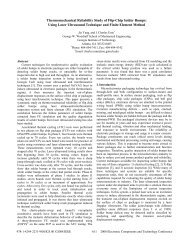
electrodeposited Cu layer was fixed at about 20µm. Thespecimens were reflowed at 260°C for 1min. After reflow, theaging tests were c<strong>on</strong>ducted at 150°C for 240, 480, 720 and960h. Drop tests were c<strong>on</strong>ducted to evaluate the mechanicalreliability <str<strong>on</strong>g>of</str<strong>on</strong>g> solder joint. Specimens were assembled usingtwo FR4 PCBs with 16 Sn-3.5Ag solder balls. Solders werereflowed <strong>on</strong> the top PCB first with either Cu foil orelectrodeposited Cu and then joined with the bottom PCB bythe 2 nd reflow. The pads <str<strong>on</strong>g>of</str<strong>on</strong>g> all bottom PCBs were Cu foilwithout electrodeposited Cu. Thus, top side was reflowed<strong>on</strong>ce more than the bottom side. The shock loading was setaccording to JESD22-B111[8] by adjusting the drop heightand accelerati<strong>on</strong>. The shock pulse from the drop impact wasoptimized to a triangular shape with the peak accelerati<strong>on</strong> <str<strong>on</strong>g>of</str<strong>on</strong>g>1500G for 0.4ms. Two PCBs were daisy-chained, and the insitudetecti<strong>on</strong> <str<strong>on</strong>g>of</str<strong>on</strong>g> the threshold resistance <str<strong>on</strong>g>of</str<strong>on</strong>g> 20Ohms was usedas a criteri<strong>on</strong> <str<strong>on</strong>g>of</str<strong>on</strong>g> complete drop failure. The test was stoppedwhen failure did not occur up to 400 drops. Scanning electr<strong>on</strong>microscopy (SEM) with energy dispersive x-ray spectroscopy(EDX) was used to investigate IMC thickness, compositi<strong>on</strong>,and the failure mode.3. Results and Discussi<strong>on</strong>s3.1 Solid state aging testThe microstructure at Cu foil/Sn-3.5Ag solder interfaceafter reflow at 260°C for 1min is shown in Fig. 1. Afterreflow process, Cu 6 Sn 5 IMC formed first at the Cu/Sn-3.5Aginterface. Cu 3 Sn was hardly detected with back scatteredelectr<strong>on</strong> (BSE) image and no voids existed at the Cu/Sn-3.5Ag interface. P A (electrodeposited Cu without additive)and P N (electrodeposited Cu with additive) showed similarmicrostructures to Fig. 1 just after reflow.case <str<strong>on</strong>g>of</str<strong>on</strong>g> P A specimen, more and larger voids were found thanthose in P N . And voids in P A were distributed close to theCu/Cu 3 Sn interface as shown in Fig. 2(b) and (c). Mei et al.[7] reported that voided area at the Cu/Cu 3 Sn interface was30% more than that <str<strong>on</strong>g>of</str<strong>on</strong>g> Chiu’s data [1], although specimensexperienced same aging c<strong>on</strong>diti<strong>on</strong>. Chiu et al. [1] indicatedthat increase <str<strong>on</strong>g>of</str<strong>on</strong>g> operating temperature accelerated intensivelyvoids formati<strong>on</strong>. Nevertheless, in the same aging c<strong>on</strong>diti<strong>on</strong>, itis sure that voids formati<strong>on</strong> str<strong>on</strong>gly depends <strong>on</strong> the Cufabricati<strong>on</strong> and depositi<strong>on</strong> c<strong>on</strong>diti<strong>on</strong>.(a)(b)Cu 6 Sn 5Cu 3 SnCu 6 Sn 5Cu 3 SnSn-3.5AgCuSn-3.5Ag5µmSn-3.5AgCu5µmCuCu 6 Sn 5(c)Sn-3.5Ag5µmFigure 1. Cross-secti<strong>on</strong>ed BSE micrographs <str<strong>on</strong>g>of</str<strong>on</strong>g> interfacialmicrostructures at Cu foil/Sn-3.5Ag interface after reflowat 260°C for 1min.Figure 2 is BSE images showing Cu/Sn-3.5Ag interfaceafter aging at 150°C for 240h. All specimens showed Cu 3 Sn 5IMC <str<strong>on</strong>g>of</str<strong>on</strong>g> typical planar shape between Cu and Cu 6 Sn 5 .However, <strong>Kirkendall</strong> voids formati<strong>on</strong> behavior wastremendously different in each specimen. As shown in Fig.2(a), the voids were hardly observed. On the other hand, P Aand P N specimens had clearly <strong>Kirkendall</strong> voids, even thoughthe amount and distributi<strong>on</strong> <str<strong>on</strong>g>of</str<strong>on</strong>g> voids were not similar. In theCu 6 Sn 5Cu 3 SnCu5µmFigure 2. Cross-secti<strong>on</strong>ed BSE micrographs after thermalaging at 150°C for 240h in (a) Cu foil, (b) P N , and (c) P Aspecimen.Figure 3 shows the microstructure <str<strong>on</strong>g>of</str<strong>on</strong>g> solder joint afteraging at 150°C for 960h. For the specimen with Cu foil,1621 2007 Electr<strong>on</strong>ic Comp<strong>on</strong>ents and Technology C<strong>on</strong>ference
egardless <str<strong>on</strong>g>of</str<strong>on</strong>g> increased aging time, voids are not visible insideCu 3 Sn layer as shown in Fig. 3(a). <strong>Void</strong>s in P N specimendistributed randomly and size was smaller than those <str<strong>on</strong>g>of</str<strong>on</strong>g> P Nspecimen [Fig. 3(b)]. However, in the P A specimen, largervoids located at near the Cu/Cu 3 Sn interface [Fig. 3(c)]. It isinteresting that <strong>Kirkendall</strong> voids were located at the Cu/Cu 3 Sninterface and suppressed the growth <str<strong>on</strong>g>of</str<strong>on</strong>g> Cu 3 Sn layer byblocking Cu diffusi<strong>on</strong> into Cu 3 Sn. This phenomen<strong>on</strong> isc<strong>on</strong>sistent with Zeng’s observati<strong>on</strong>. [5] Cu 3 Sn layer werec<strong>on</strong>verted to Cu 6 Sn 5 layer because voids blocked Cudiffusi<strong>on</strong>. Therefore, Cu 6 Sn 5 layer became thicker than Cu 3 Snlayer as shown in Fig. 3(c).(a)(b)(c)Cu 6 Sn 5Cu 6 Sn 5Cu 3 SnCu 3 SnSn-3.5AgCu 6 Sn 5Cu 3 SnCuSn-3.5AgCuSn-3.5AgCu5µm5µm5µmFigure 3. Cross-secti<strong>on</strong>ed BSE images after thermal agingat 150°C for 960h in (a) Cu foil, (b) P N , and (c) P A specimen.For the growth kinetics <str<strong>on</strong>g>of</str<strong>on</strong>g> Cu 6 Sn 5 and Cu 3 Sn layer, totalIMC thickness and relative fracti<strong>on</strong>s <str<strong>on</strong>g>of</str<strong>on</strong>g> the two IMCs weremeasured after thermal aging at 150°C as shown in Fig. 4.Total IMC growth behavior appeared as a functi<strong>on</strong> <str<strong>on</strong>g>of</str<strong>on</strong>g> squareroot <str<strong>on</strong>g>of</str<strong>on</strong>g> time about all specimens as given in Fig. 4(a). Sincetwo types <str<strong>on</strong>g>of</str<strong>on</strong>g> IMCs were formed in each specimen, thickness<str<strong>on</strong>g>of</str<strong>on</strong>g> Cu 6 Sn 5 and Cu 3 Sn was measured separately and the ratio <str<strong>on</strong>g>of</str<strong>on</strong>g>Cu 3 Sn layer to total IMC was calculated. Ratio <str<strong>on</strong>g>of</str<strong>on</strong>g> Cu 3 Sn layerto total IMC was about 50% except P A specimen, while ratio<str<strong>on</strong>g>of</str<strong>on</strong>g> Cu 3 Sn to total IMC for P A specimen decreased with theaging time.Total IMC thickness (µm)δ Cu3 Sn /δ total (%)10987654321Cu foilP NP A00 200 400 600 800 1000Aging time (hr)(a)100Cu foilP N80604020P A00 200 400 600 800 1000Aging time (hr)(b)Figure 4. Variati<strong>on</strong> <str<strong>on</strong>g>of</str<strong>on</strong>g> (a) total IMC thickness and (b)ratio <str<strong>on</strong>g>of</str<strong>on</strong>g> Cu 3 Sn to total IMC thickness.Figure 5 showed voided area between Cu and Cu 3 Sn andratio <str<strong>on</strong>g>of</str<strong>on</strong>g> voided length to Cu/Cu 3 Sn interface length measuredby image analyzing program. A comparis<strong>on</strong> between voidedarea <str<strong>on</strong>g>of</str<strong>on</strong>g> P A and P N specimens shows that more voids in P Aspecimen grew between Cu and Cu 3 Sn layer. When voiddensity increased at the Cu/Cu 3 Sn interface, voids coalescedinto disk shape and did not migrate into Cu 3 Sn layer. On theother hand, voids migrate with the growth <str<strong>on</strong>g>of</str<strong>on</strong>g> Cu 3 Sn layer asvoid density between Cu and Cu 3 Sn layer is not high. It is1622 2007 Electr<strong>on</strong>ic Comp<strong>on</strong>ents and Technology C<strong>on</strong>ference
clear that randomly distributed small voids in Cu 3 Sn layeraffect much less to the diffusi<strong>on</strong> <str<strong>on</strong>g>of</str<strong>on</strong>g> Cu into Cu 3 Sn as indicatedin Fig. 4.<strong>Void</strong>ed area / total IMC area (%)% voided length10864200 200 400 600 800 1000Aging time (hr)10080604020P NP AP NP A(a)appears that brittle fracture occurred at the interface betweenCu 3 Sn and Cu 6 Sn 5 . Recently, it has been reported that brittlefracture occurred al<strong>on</strong>g the interface between Cu 3 Sn andCu 6 Sn 5 layer for Sn-Ag-Cu solder joint with Cu metallizati<strong>on</strong>,although no mechanisms were suggested about inter-IMCfailure, yet [9,10]. Therefore, crack propagates much easieral<strong>on</strong>g the interface <str<strong>on</strong>g>of</str<strong>on</strong>g> layered two IMC, Cu 3 Sn and Cu 6 Sn 5 ,than other locati<strong>on</strong>s as reported in our previous work [11].N f35030025020015010050Cu foilP A00 200 400 600 800 1000Aging time (hr)Figure 6. Number <str<strong>on</strong>g>of</str<strong>on</strong>g> drops to failure vs. aging time.(a)Sn-3.5Ag00 200 400 600 800 1000Aging time (hr)(b)Figure 5. (a) Ratio <str<strong>on</strong>g>of</str<strong>on</strong>g> voided area to total IMC area and(b) ratio <str<strong>on</strong>g>of</str<strong>on</strong>g> voided length to Cu/Cu 3 Sn interface length3.2 Drop impact testDrop impact test was c<strong>on</strong>ducted to c<strong>on</strong>firm effect <str<strong>on</strong>g>of</str<strong>on</strong>g> voidformati<strong>on</strong> at the Cu/Cu 3 Sn interface. Mean cycles to failurefor board level drop tests are presented in Fig. 6 where effect<str<strong>on</strong>g>of</str<strong>on</strong>g> voids occupied at the Cu/Cu 3 Sn interface is clearlydem<strong>on</strong>strated. It is very interesting that two opposite trendswere identified for the drop tests. For the tests with Cu foil,drop resistance <str<strong>on</strong>g>of</str<strong>on</strong>g> as-reflowed specimens was poor incomparis<strong>on</strong> to thermally aged specimens. On the c<strong>on</strong>trary, forthe tests with P A , drop resistance decreased drastically withthe thermal aging at 150°C. Cross-secti<strong>on</strong>al BSE images <str<strong>on</strong>g>of</str<strong>on</strong>g>failed specimens reveal the path <str<strong>on</strong>g>of</str<strong>on</strong>g> crack propagati<strong>on</strong> aspresented in Fig. 7 and 8. Brittle failure occurred at theinterface <str<strong>on</strong>g>of</str<strong>on</strong>g> solder joints about all specimens, although dropresistance <str<strong>on</strong>g>of</str<strong>on</strong>g> specimens is quite different. Fig. 7 shows failedinterface <str<strong>on</strong>g>of</str<strong>on</strong>g> solder joint with Cu foil after reflow at 260°C for1min. Focused i<strong>on</strong> beam(FIB) image as shown in Fig. 7(b)(b)Cu 3 SnCu 6 Sn 5Cu 3 SnCu 6 Sn 5Sn-3.5AgCuCu5µm3µmFigure 7. (a) BSE and (b) FIB images <str<strong>on</strong>g>of</str<strong>on</strong>g> as-reflowedsolder joint with Cu foil after drop test.1623 2007 Electr<strong>on</strong>ic Comp<strong>on</strong>ents and Technology C<strong>on</strong>ference
Brittle failure loci for solder joints aged at 150°C for 480hwere presented in Fig. 8. Although brittle failure occurred atthe solder joints, failure site was different and depended <strong>on</strong><strong>Kirkendall</strong> void formati<strong>on</strong>. In the case <str<strong>on</strong>g>of</str<strong>on</strong>g> specimens with Cufoil, dominant crack propagati<strong>on</strong> occurred at theCu 3 Sn/Cu 6 Sn 5 interface as shown in Fig. 8(a). From Fig. 7and 8(a), it can be seen that the Cu 3 Sn/Cu 6 Sn 5 interface is not<strong>on</strong>ly weak site but dominant crack path regardless <str<strong>on</strong>g>of</str<strong>on</strong>g> Cu 3 SnIMC thickness. For the specimens with P A , brittle fractureoccurred al<strong>on</strong>g the voids formed at the Cu/Cu 3 Sn interface asshown in Fig. 8(b). As shown in reacti<strong>on</strong> study, voidsoccupied completely at the interface between Cu and Cu 3 Snafter aging at 150°C for 480h and the growth <str<strong>on</strong>g>of</str<strong>on</strong>g> Cu 3 Sn IMCwas prohibited by voids. Brittle failure occurred al<strong>on</strong>g thevoids formed at the Cu/Cu 3 Sn interface. As shown in Fig.6.drop resistance is very weak when a large amount <str<strong>on</strong>g>of</str<strong>on</strong>g> voidsexist at the Cu/Cu 3 Sn interface. From plane view images <str<strong>on</strong>g>of</str<strong>on</strong>g>specimen with P A after drop test as shown in Fig. 9, it wasclearly dem<strong>on</strong>strated that fractured interface has an extremelyporous structure, which gives very weak chemical adhesi<strong>on</strong>between Cu 3 Sn intermetallics and Cu. Based <strong>on</strong> the abovedrop impact results, it can be sure that <strong>Kirkendall</strong> voidsformati<strong>on</strong> <str<strong>on</strong>g>of</str<strong>on</strong>g> solder joint str<strong>on</strong>gly correlated with dropreliability. Additi<strong>on</strong>ally, to improve mechanical reliability <str<strong>on</strong>g>of</str<strong>on</strong>g>solder joints with Cu film needs to decrease <strong>Kirkendall</strong> voidsaccumulated at the interface between Cu 3 Sn and Cu.(a)(b)(a)(b)Cu 3 SnCu 6 Sn 5Cu 3 SnCu 6 Sn 5Sn-3.5AgCu 5µmCuSn-3.5Ag5µmFigure 8. Failure morphology <str<strong>on</strong>g>of</str<strong>on</strong>g> (a) specimen with Cu foiland (b) P A after aging at 150°C for 480h.Figure 9. Plane views <str<strong>on</strong>g>of</str<strong>on</strong>g> solder joint with P A after aging at150°C for 480h (a) x100 and (b) x5000.C<strong>on</strong>clusi<strong>on</strong>sInterfacial reacti<strong>on</strong> study and drop impact test <str<strong>on</strong>g>of</str<strong>on</strong>g> Sn-3.5Ag solder joint with OHFC Cu foil or electrodeposited Cufilms were performed after thermal aging at 150°C. Additiveinfluenced very critically to the locati<strong>on</strong> as well as theformati<strong>on</strong> <str<strong>on</strong>g>of</str<strong>on</strong>g> <strong>Kirkendall</strong> void. Behavior <str<strong>on</strong>g>of</str<strong>on</strong>g> IMC growth wereinfluenced by <strong>Kirkendall</strong> voids because Cu diffusi<strong>on</strong> wereblocked by voids. Specimen <str<strong>on</strong>g>of</str<strong>on</strong>g> Cu foil after thermal agingshowed the failure loci through the interface between Cu 3 Snand Cu 6 Sn 5 because <str<strong>on</strong>g>of</str<strong>on</strong>g> brittle properties at the interface.Specimen <str<strong>on</strong>g>of</str<strong>on</strong>g> P A after thermal aging showed the failure locithrough the interface between Cu 3 Sn and Cu 6 Sn 5 because <str<strong>on</strong>g>of</str<strong>on</strong>g><strong>Kirkendall</strong> voids.AcknowledgmentsThis work was supported by the Center for Electr<strong>on</strong>icPackaging Materials (ERC) <str<strong>on</strong>g>of</str<strong>on</strong>g> MOST/KOSEF. (grant # R11-2000-085-05001-0)References1. Chiu, T.-C., Zeng, K, and Stierman, R., Edwards, D., andAno, K., “<str<strong>on</strong>g>Effect</str<strong>on</strong>g> <str<strong>on</strong>g>of</str<strong>on</strong>g> Thermal Aging <strong>on</strong> Board Level DropReliability for Pb-free BGA Packages”, Proc <str<strong>on</strong>g>of</str<strong>on</strong>g> 54 thElectr<strong>on</strong>ic Comp<strong>on</strong>ents and Technology C<strong>on</strong>f, Las Vegas,NV, June. 2004, pp. 1256-1262.1624 2007 Electr<strong>on</strong>ic Comp<strong>on</strong>ents and Technology C<strong>on</strong>ference
2. Zeng, K., Stierman, R., Chiu, T.-C., Edwards, D., Ano K.,and Tu, K. N., “<strong>Kirkendall</strong> <strong>Void</strong> Formati<strong>on</strong> in EutecticSn-Pb Solder Joint <strong>on</strong> Bare Cu and Its <str<strong>on</strong>g>Effect</str<strong>on</strong>g> <strong>on</strong> JointReliability”, J. Appl. Phy., 97, 024508 (2005).3. Xu, L. and Pang, John H. L., “<str<strong>on</strong>g>Effect</str<strong>on</strong>g> <str<strong>on</strong>g>of</str<strong>on</strong>g> Intermetallic and<strong>Kirkendall</strong> <strong>Void</strong>s Growth <strong>on</strong> Board Level Drop Reliabilityfor SnAgCu Lead-free BGA Solder Joint”, Proc <str<strong>on</strong>g>of</str<strong>on</strong>g> 56 thElectr<strong>on</strong>ic Comp<strong>on</strong>ents and Technology C<strong>on</strong>f, San Diego,CA, June. 2006, pp. 275-282.4. Yu, Jin, Sohn, Y. C., Kim, J. Y., Jee, Y. K., and Ko, Y.H., “Impact reliabilities <str<strong>on</strong>g>of</str<strong>on</strong>g> lead-free solder joints withNi(P), Cu and Ni metallizati<strong>on</strong>s”, Proc <str<strong>on</strong>g>of</str<strong>on</strong>g> 2006Internati<strong>on</strong>al C<strong>on</strong>ference <strong>on</strong> Electr<strong>on</strong>ics Packaging,Tokyo, April. 2006.5. Laurila, T., Vuorinen, V., and Kivilahti, J. K., “Interfacialreacti<strong>on</strong>s between lead-free solders and comm<strong>on</strong> basematerials”, Mater. Sci. Eng., R 49 (2005), pp.1-60.6. Yang, W and Messler, R. W., “Microstructure Evoluti<strong>on</strong><str<strong>on</strong>g>of</str<strong>on</strong>g> Eutectic Sn-Ag Solder Joints”, J. Electr<strong>on</strong>. Mater., Vol.23, No. 8 (1994), pp. 765-772.7. Mei, Z., Ahmad, M., Hu, M., and Ramakrishna, G.,“<strong>Kirkendall</strong> <strong>Void</strong>s at Cu/Solder Interface and Their<str<strong>on</strong>g>Effect</str<strong>on</strong>g>s <strong>on</strong> Solder Joint Reliability”, Proc <str<strong>on</strong>g>of</str<strong>on</strong>g> 55 thElectr<strong>on</strong>ic Comp<strong>on</strong>ents and Technology C<strong>on</strong>f, Orlando,FL, June. 2005, pp. 415-420.8. JESD22-B111, “Board Level Drop Test Method <str<strong>on</strong>g>of</str<strong>on</strong>g>Comp<strong>on</strong>ents for Handheld Electr<strong>on</strong>ic Products”, JEDECstandard, July. 2003.9. Shin, D. K., Lee, D. Y., Ahn, E. C., Kim, T. H., and Cho,T. J., “Development <str<strong>on</strong>g>of</str<strong>on</strong>g> Multi Stack Package with HighDrop Reliability by Experimental and NumericalMethods”, Proc <str<strong>on</strong>g>of</str<strong>on</strong>g> 56 th Electr<strong>on</strong>ic Comp<strong>on</strong>ents andTechnology C<strong>on</strong>f, San Diego, CA, June. 2006, pp. 377-382.10. Jang, J. W., A.P. De Silva, A. P., Drye, J. E., Post, S. L.,Owens, N. L., Lin, J. K., and Frear, D. R., “Drop Test andFailure Mechanism <str<strong>on</strong>g>of</str<strong>on</strong>g> Sn-3.8Ag-0.7Cu and Sn-37PbSolders in BGA Packages”, Proc <str<strong>on</strong>g>of</str<strong>on</strong>g> 39 th Internati<strong>on</strong>alMicroelectr<strong>on</strong>ics and Packaging Society, San Diego, CA,October. 2006, pp. 357-364.11. Kim, J. Y., Sohn, Y. C., and Yu, Jin, “<str<strong>on</strong>g>Effect</str<strong>on</strong>g> <str<strong>on</strong>g>of</str<strong>on</strong>g> Cuc<strong>on</strong>tent <strong>on</strong> the mechanical reliability <str<strong>on</strong>g>of</str<strong>on</strong>g> Ni/Sn–3.5Agsystem”, J. Mater. Res., In press (2007).1625 2007 Electr<strong>on</strong>ic Comp<strong>on</strong>ents and Technology C<strong>on</strong>ference