danger - ESCO Tire Service Equipment
danger - ESCO Tire Service Equipment
danger - ESCO Tire Service Equipment
- No tags were found...

Create successful ePaper yourself
Turn your PDF publications into a flip-book with our unique Google optimized e-Paper software.
REV0709Cut Away<strong>Tire</strong> Bead BreakerModel 10102
REV0709Parts List For<strong>Tire</strong> Bead BreakerModel 10102Item Part No.No. DescriptionNo.Req’d1 12901 1 Screw, Hex Hd Cap (7/16-14 x 2) Torque to 30/40 Ft. Lbs2 36949 1 Handle, Strap Pivot3 350455 1 Piston, (Single Jaw)4 350456 1 Body, Cylinder (Single Jaw; Torque to 125/140 Ft. Lbs.)5 16720 1 Rod Wiper6 10442 1 Washer, Copper7 16721 1 U-cup8 10020 1 Screw, Soc Hd (1/4-20 x 1-1/4; Torque to 90/110 in. Lbs.9 11116 (SEE BC2516027A) 1 Screw, Set (1/4-20 x 1)10 201360 1 Spring, Retainer11 201430 1 Spring, (.83 OD x 1.90 x .13 WS)12 17160 (SEE DA10494167) 1 Washer, Special (1.00 x .26)13 13944 (SEE DA10492110) 1 Spring, (.36 OD x .50 x .05 WS)14 10375 1 Ball, (1/4 in. Dia. Steel)
REV0709Parts List For<strong>Tire</strong> Bead BreakerModel 10102Item No. Part No. No. Req’d Description15 11841 1 O Ring, (1.62 x 1.37 Nitrile)16 206751 1 Washer, Backup (2.00 x 1.75)17 16724 1 Spring, (.32 OD x 1.20 x .08 WS)18 10375 1 Ball, (1/4” Dia. Steel)19 10261 1 Washer, Copper (.75 x .60)20 10020 1 Screw, Soc Hd (1/4-20 x 1-1/4; Torque to 90/110 in. Lbs.21 10613 1 Pin, Roll (.38 x 2.25)22 36853 1 Claw, Machining23 10442 1 Washer, Copper24 250918 1 Wiper, Rod (2.00 x 1.50 URE)25 BC380627B 1 Screw, Set (3/8-16 x ½)26 16721 1 U-cup27 DA11382027 1 Screw, Set (3/8-16 x 3/8)28 64250 1 Body, Beak Breaker29 420439 1 Piston, Cylinder30 204237 1 Ring, Retainer (internal 141 ID)31 204236 1 Bearing32 201433 1 Ring, Retainer (internal 1/31 ID)33 201360 1 Spring, Retainer34 10294 1 O Ring, (2.00 x 1.75 Nitrile)35 206750 1 Washer, Backup (2.00 x 1.75)36 F100009-59 1 Plug, End (Torque to 140/225 Ft. Lbs.)37 202636 1 Handle38 10391 1 Nut, Hex Jam (1/2-13)39 16064 1 Screw, Soc Hd (1/4-20 x 3-1/2; Torque to 90/110 in. Lbs.)40 10442 1 Washer, Copper (.37 x .25)41 202625 1 Spring, (.83 OD x 5.00 x .13 WS)42 10606 1 Ram Half Cplr/plastic dust cap43 12223 1 Ball, (3/16” Dia. Steel)44 10622 1 Fitting, Elbow 45 Deg (3/8 NPTF)
REV0709*NOTE – Identifying feature DA Number cast on clamp Item# 47.Repair Parts SheetModel 10102<strong>Tire</strong> Bead BreakerNRCAUTIONThe BBH-40 Bead Breaker, and all tiretools, should be used only be personsproperly trained according to OSHAregulation #29CFR1910.177,“Servicing Single-Piece & Multi-PieceWheels.”
REV0709REPAIR PARTS LISTITEM PART NO. QTY. DESCRIPTION ITEM PART NO. QTY. DESCRIPTION1 B1564046 (SEE 10291) 1 CAP SCREW 25DA10506149 (SEE204237)1 RETAINING RING2 DA10487070 (SEE 36949) 1 STRAP PIVOT 26DA10490155 (SEE204236)1 BEARING3 DA10486051 1 PISTON 27DA10509149 (SEE201433)1 RETAING RING4 DA10485030 1 CYLINDER 28 *B1090503 (SEE 10294) 1 O-RING5 *DA10507776 (SEE 16720) 1 ROD WIPER 29*B1224564 (SEE206750)1 BACK UP6 *DA10493167 (SEE 10442) 3 COOPER WASHER 30 DA10477020 1 SPRING HANDLE CAP7 *DA10502041 (SEE 16721) 2 DISOGRIN U-CUP 31 B1009123 (SEE 10391) 1 JAM NUT8 B1013028 (SEE 10020) 2SOCKET HEADDA104181070 (SEE32CAPSCREW202636)1 SPRING RETURN ASSEMBLY9 BC2516027A 1 SET SCREW 33DA10496028 (SEE16064)1 CAP SCREW11 DA10330900 (SEE 201430) 1SPRING RETURNDA10503776 (SEE34ASSEMBLY250918)1 SPRING RETURN ASSEMBLY12 DA10494167 1 STEEL WASHER 35 10606 1 FEMALE COUPLER13 *DA10492110 1COMPRESSIONSPRING36 F100009-59 1 EXPANDER RING14 *B1026503 (SEE 11841) 1 O-RING 37 *DA10503776 1 METAL CAP ASSEMBLY15 *B1221564 (SEE 206751) 1 BACK-UP 38 DA4338900 (SEE 9797) 1 DUST CAP ASSEMBLY16 *B1007016 (SEE 10375) 2 ¼” DIA. BALL 39DA10508349 (SEE11901)4 SNAP RING17 *DA10279110 (SEE 16724) 1 COMPRESSION RING 40 350270 2 SIDE STRAP18 *DA10495167 (SEE 10261) 1 COPPER WASHER 41 DA10482020 1 CAP19 B1171057 (SEE 10613) 1 ROLL PIN 42 B1139028 4 SOCKET HEAD CAPSCREW20 DA10491002L (SEE 36853) 1 CLAW AMCHINE 43DA10504800L (SEE306135)2 REPLACEMENT TOOTH21 BC3806027B 1 SET SCREW 44 B1069028 2 SOCKET HEAD CAPSCREW22 DA11382027 1 SET SCREW 45DA10500039 (SEE204238)2 BUSHING23 DA10480107 1 RAM PISTON 46 DA10488061 1 HANDLE PIN24 DA10478001 (N/A) 1 BODY 47DA10484639L (SEE420438)1 JAW CLAMP* Indicates parts available in Repair Kit 10701
REV0709Parts List For<strong>Tire</strong> Bead BreakerModel 10102*NOTE – Identifying feature 5 digit number cast on clamp Item# 11Item No. No. Req’d Part No. Description1 2 11901 Ring, Retainer External2 2 260095 Decal, Warning3 2 DA10489217 Strap4 1 21599 Screw, Cap (9/16-18 x 1 –1/8)5 4 10081 Screw, Soc Hd (1/2-13 x 1-1/4)6 2 306135-1 Tooth, Replaceable7 2 B1069028 Screw, Soc Hd (3/8-16 x 1)8 2 204238 Spacer9 1 DA10488061L Pin10 2 11901 Ring, Retainer External*11 1 420438L Jaw, Single
10102 “Maxi” Bead BreakerInstruction ManualWorld Leader In <strong>Tire</strong> Changing <strong>Equipment</strong>15270 Flight Path Drive • Brooksville, FL 34604 USAPhone: (352) 754-1117 • Fax: (352) 754-4508www.esco.net • sales@esco.net
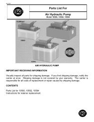
Instruction Manual10102 "Maxi" <strong>Tire</strong> Bead BreakerL2190 Rev. O.1 10/07IMPORTANT RECEIVING INFORMATIONCONTENTSVisually inspect all parts for shipping damage. If you find shipping damage, notify the carrier atonce. Shipping damage is not covered by your warranty. The carrier is responsible for all costs ofreplacement or repair caused by shipping damage.ENGLISH.........................................3-7 FRANÇAIS ................13-17 ITALIANO..............23-27DEUTSCH .......................................8-12 ESPAÑOL ..................18-22 NEDERLANDS ......28-32DESCRIPTIONThe BBH-40 Bead Breaker is used on all types of rims except 5-piece earthmover rims. It is idealfor use with truck, farm tractor, grader, combine, and skidder tires. The BBH-40 can be used with amodel AHP15T (10500), AHP25TP (10502), AHP35T (10504), or equivalent 10,000 psi [700 bar]pump.SAFETY INFORMATIONTo avoid personal injury or property damage while using this product, read and follow allDANGERS, WARNINGS, CAUTIONS, and INSTRUCTIONS that are attached to, or includedwith, this product.1. Follow the instructions of the tire manufacturer and the vehicle manufacturer when deflating,demounting, mounting, and inflating tires.2. These operating instructions do not apply to any specific rim. Therefore, contact the rimmanufacturer for the correct procedure for your rim.3. For the publication, “Multipiece Rim Matching Chart” contact the United States Departmentof Labor, Occupational Safety, and Health Administration (OSHA), Washington, DC, 20210,202-219-6091, or contact <strong>ESCO</strong> at 1-800-352-9852. If you are outside the U.S., contact yourlocal government officials.4. <strong>ESCO</strong> cannot be held responsible for damage or injury resulting from unsafe use of thisproduct; lack of maintenance; or incorrect product and system application.5. Contact <strong>ESCO</strong> when in doubt about safety precautions or applications.A CAUTIONThe bead breaker, and all tire tools, should be used only by persons properly trained accordingto OSHA Regulation #29CFR1910.177, “Servicing Single-Piece & Multi-Piece Wheels.” Free copiesof this regulation are available upon request from <strong>ESCO</strong>.A WARNINGTo avoid serious personal injury, always wear proper protective gear, such as hard hats, safetyglasses, gloves, and steel toe shoes when using hydraulic equipment.- 3 -
OPERATING INSTRUCTIONSREMOVING THE WHEEL1. Chock the wheels opposite the jack.2. Jack up the vehicle.3. Crib the vehicle with safety stands or blocking devices after jacking it up. Do not work under anunblocked load.A DANGERFailure to chock the wheels and crib the vehicle can result inserious injury or death.4. Remove the valve core; deflate tires completely. (See Fig. 1.)5. Insert a thin piece of wire through the valve stem to make sureair is flowing freely and the valve stem is not blocked.NOTE: Deflate both tires if you have a dual mounting.A DANGERFigure 1Always deflate tires before removing a wheel, a rim, or part of a rim, such as a rim clamp or nut.If you do not deflate the tire, the tire could explode, causing serious injury or death.6a. If you are breaking the tire bead with the wheel on the vehicle: Proceed to “Positioning the BeadBreaker” below.6b. If you are breaking the tire bead with the wheel off the vehicle: Remove the tire/rim assembly fromthe vehicle and place it flat on the ground with the gutter side up. Then proceed to “Positioning theBead Breaker” below.USING THE 10102 BEAD BREAKERPositioning the Bead BreakerPosition the bead breaker, so that the wedge-shaped teeth willgrab evenly under the rim flange when the clamping jawtightens. (See Fig. 2.)NOTE: Make sure the bead breaker is about 30°, or at least12 inches [0,3 m], to one side of the flange butt weld.Activating the Bead BreakerA CAUTIONThe bead breaker uses a long stroke and high force. Becareful not to damage or bend rim parts, such as the flangebutt weld, when using the bead breaker.1. Run the air hydraulic pump so that the clamping jaw begins totighten against the rim. (See Fig. 3.) Make sure the wedgeshapedteeth are placed well into the tire bead and against therim flange.NOTE: To grab the rim flange evenly, you may have to tryseveral times. Do not force the bead breaker when grabbingthe flange.2. Continue to apply hydraulic pressure until the bead breakingram extends about 1/4 inch [6,35 mm] from the bead breaker.(See Fig. 4.)Figure 2Figure 3- 4 -Figure 4
3. Maintain the bead breaker, so that it is nearly perpendicular(90°) to the rim.(See Fig. 5.) If necessary, adjust theposition of the bead breaker.4. Step away from the bead breaker. (See Fig. 6.)A DANGERAlways stand to one side of the rim when using the beadbreaker. Standing to one side of the bead breaker allowsyou to maintain control of the bead breaker.Do not hold the bead breaker when breaking the tire bead.If it is not seated properly and flies off the rim, the beadbreaker could cause serious injury or death.5. Continue to apply hydraulic pressure until the beadbreaking ram extends about 1/2 - 3/4 inch [13-19 mm] fromthe bead breaker. (See Fig. 7.)NOTE: Never try to break the tire bead with only one push.Instead, proceed to “Continuing to Break the <strong>Tire</strong> Bead”below.Continuing to Break the <strong>Tire</strong> Bead1. Move the bead breaker 8-12 inches [0,2-0,3 m] from itscurrent position.2. Repeat steps, starting with “Positioning the BeadBreaker”, until the rim is completely separated from thetire bead.Breaking the Bead on the Other Side1. Turn the tire over on the other side.2. Repeat all steps, starting with “Positioning the <strong>Tire</strong> Bead”on page 2.Figure 5Figure 6Figure 7MOUNTING AND INFLATIONJacking Up the Vehicle1. Chock the wheels opposite the jack.2. Jack up the vehicle.3. Crib the vehicle with safety stands or blocking devices after jacking it up. Do not work under anunblocked load.A DANGERFailure to chock the wheels and crib the vehicle can result in serious injury or death.- 5 -
Inspecting the <strong>Tire</strong> and RimA DANGERAlways replace damaged or badly worn tires. When replacing tires, always use a replacement ofexactly the same diameter. Destroy old tires, so that they cannot be used. Using badly worn ordamaged tires can result in serious injury or death.1. Inspect all rim parts for damage.A DANGERAlways replace rim parts that are bent, badly rusted, pitted from corrosion, cracked, worn, ordamaged. Destroy old rim parts, so they cannot be used. Using damaged rim parts can result inserious injury or death.Do not mix parts from one rim with parts from another rim. Always use replacement parts thatyou can positively identify as the CORRECT replacement parts. All replacement rim parts MUSTmatch the replacement part numbers stamped on the rim parts. Rims with different part numberscannot be interchanged. If in doubt about sizing, DO NOT reassemble the rim. Contact the rimmanufacturer for more information.2. Replace damaged parts.A DANGERNever weld on an inflated or partially inflated tire/rim assembly. Welding on an inflated tire/rimassembly can cause an explosion and serious injury or death.Do not rework, weld, heat, or braze any rim parts for any reason. Reworking and weldingdamaged parts can result in serious injury or death.3. Clean and repaint rim parts as necessary.NOTE: Remove rust, dirt, and foreign material from rim parts. Repainting the rim parts and baremetal areas will make them last longer. Be careful to keep paint out of the lock ring groove in thegutter when repainting rim parts.4 Visually inspect all tire and rim parts to make sure they are positioned properly.Starting to Inflate the <strong>Tire</strong>1. To comply with OSHA Regulation #29CFR1910.177, place the tire in a safety cage or otherrestraining device before inflating the tire. Use a clip-on air chuck and hose that is long enough toallow you to stand outside the wheel trajectory. The air line must be equipped with an in-line valvewith pressure gauge or regulator that can be preset. Use <strong>ESCO</strong> Truck <strong>Tire</strong> Inflator Model 15136.A DANGERAlways use a safety cage or restraining device when inflating a tire. Not using a safety cage orrestraining device can result in serious injury or death.Always use a clip-on air chuck and a hose that is long enough to allow you to stand outside thewheel trajectory. The air line must be equipped with an in-line valve with a pressure gauge or aregulator that can be preset.Never use starting fluid, ether, gasoline, or any other flammable material to lubricate, seal, or seatthe bead of a tubeless tire. Doing so can cause an explosion and serious injury or death.2. Inflate the tire to 5 psi [0,345 bar].3. Check all tire and rim parts again for proper positioning.4. If tire/rim parts are not seated properly, deflate the tire and correct the problem before proceeding.- 6 -
A WARNINGNever hammer, strike, or pry an inflated or partly inflated tire/rim assembly. If you must seat apart or correct a problem, always deflate the tire first.A CAUTIONDo not use a steel hammer on rim or rim parts. This can damage the rim. If you must repositiontire or rim parts, use a rubber, plastic, or brass-faced hammer.If a tire/rim assembly does not slide over a cast spoke wheel: Do not force the assembly byhammering. Instead, deflate the tire and inspect for warped or incorrectly seated parts, such aslock rings.5. If tire and rim parts are seated properly proceed to “Finishing the <strong>Tire</strong> Inflation” below.Finishing the <strong>Tire</strong> Inflation1. Inflate the tire to 20 psi [1,38 bar].2. Check the tire bead for proper seating.3. Continue inflating the tire to 40 psi [2,76 bar]. If the tire bead is not fully seated, see the Warningbelow. If the tire bead is fully seated, continue with Step 4 below.A WARNINGNever inflate a tire beyond 40 psi [2,76 bar] to seat a tire bead. If the tire bead is not fully seatedat 40 psi [2,76 bar]: Stop! Deflate the tire and correct the problem.4. Once you see that the tire bead is fully seated at 40 psi [2,76 bar], deflate the tire completely.5. Reinflate the tire slowly to the manufacturer’s recommended pressure.A DANGERInflate and load tires only to manufacturer’s specifications. Over-inflating and overloading tirescan result in serious injury or death.Never run a vehicle with only one tire of a dual assembly. Doing so can result in a collapse of thevehicle, leading to possible serious injury or death.- 7 -
REV0709Repair Parts SheetTurbo II Air Hydraulic PumpModel 10500, 10502, 10504(AHP-15T, AHP-25TP, AHP-35T))Install all kit components to insure optimum performance of the repaired unit.NOTE: Storing the pump in the vertical position may cause it to lose its prime. If pump loses its prime:1. Remove cover.2. Remove relief valve.3. Fill chamber with oil.4. Replace relief valve. Apply Loctite 545 to threads and torque to 10–12 ft-lbs. [14–16 Nm].5. Replace pump cover. Tighten fasteners according to torquing sequence on Figure 1, page 2.AHP-15TAHP-35TAHP-25TP(10502)ContentsFigure 1 — Treadle Assembly, AHP-15T, AHP-25TP 2 Figure 5 — Air Motor Assembly 6Figure 2 — Treadle Assembly, AHP-35T 3 Figure 6 — Cover Assembly 7Figure 3 — Hydraulic Section Detail 4 Figure 7 — Release Valve 8Figure 4 — Seal Push Tool 5
REV0709Torque to 17-19 in-lbs. [2 Nm]Torque to 6-8 in-lbs. [8-11 Nm]Torque to 17-19 in-lbs. [3 Nm]tighten using sequence shown onBoth SidesThe gasket is to be oriented withthis opening in the same cornersSight glass locationas the fill plug on the cover.on reservoirGasket orientation detail andTorque to 17-19 in-lbs [2 Nm].cover screw torquing sequenceItems 120 and 121 shown in this view only,for optional mtg. bracket "B" designation.Figure 1Repair Parts List for Figure 1Item Part Number Qty. Description Item Part Number Qty. Description1 DA12288022 1 Sight Glass 92 DC1523028 2Slotted Hex Washer HeadScr.2 B1908503 1 O Ring 94 DA4849218 1 Treadle50 DC4321900SR 1 Reservoir, 2 L, Yellow 95 DA4236242 2 Shoulder ScrewDC4320900SR 1 Reservoir, 5 L, Black 111 DC1146026 2 Decal, Esco (AHP-15T, AHP-35T)51 DC4027167 1 Reservoir Gasket, 2 L DC825026 2 Decal, Esco (AHP-25TP)DC714517 1 O-ring Gasket Cover, 5 L 110 DA4296026 1 Model No. Decal54 DA5938028 12 Hi Lo Screw 120 DA5389111 1 Mounting Bracket90 DA8625116 1 Muffler 121 DA5938028 4 Hi Lo Screw91 DA5690098 1 Muffler Cover
REV0709 Items included in pump repair kit PAT1100K.Torque to 15-20 lb-in.55565456Torque to 15-20 lb-in. Tighter using sequenceshown on "Gasket Orientation Detail".(8 - places)535251Torque to 25-30 lb-in. tightenusing sequence shown on4325 1 310719 856246Gasket Orientation Detail and5758Figure 2Repair Parts List for Figure 2Item Part Number Qty. Description Item Part Number Qty. Description1 DA11741025 1 2 Gallon reservoir 53 B1221503 1 0-Ring2 DA11720037 1Reservoir Gasket TopPlate54 B2521028 8 BHC Screw- .250-20x. 75 lg.3 DA11730101 1 Plate 55 DC4487028 4 Cap screw4 B2525028 10 BHC Screw 56 DC1063108 12 Sealing Washer5 B1015066 14 Washer, Lock, .250 57 B1015066 4 Lock Washer .2506 B1001122 14 Hex Nut (.250-20) 58 B1001122 4 Hex Nut (.250-20)51 DA7933167 1 Gasket 110 DA6197028 4 Screw52 DC460900SR 1 Intake Tube
REV0709 Items included in pump repair kit PAT1100K.Notes:1. Lubricate seals with moderate amount of DS-ES grease.2. Apply Loctite 545 on threads, and apply 10–12 ft-lbs. [14-16 Nm] of torque to item #6. Set at 10,400 to11,000 psi.3. Apply Loctite 243 on threads and apply 34–41 ft-lbs. [46-55 Nm] of torque to item #8 and #134. Apply one drop of Loctite 242 on threads, and apply 16–18 ft-lbs. [22-24 Nm] of torque to item #185. Items #24 and #25 are installed finger tight.6. Apply a 1/2 bead of Loctite 243 on threads and apply 38-45 ft-lbs. of torque to item #8.14 — See note #115 — See note #114 — See note #113 — See note #3See note #6 — 8See note #2 — 61211109720212223 — See note #1111997See note #6—82118 — See note #417 — Bearing to be installed withchamfer to the outside16 — Install U-cup with grooveside towards mountingSee note #5 - 535 — Sharp edge awayfrom mounting bracket43 — See note #1See note 4 #5 - 53SECTION A-AFigure 3
REV0709Repair Parts List for Figure 3Item Part Number Qty. Description Item Part Number Qty. Description1 DC114030 1 Hydraulic Cylinder, Turbo 10 KSI 14 DA4974367 2 Backup Ring2 DA4298108 1 Washer 15 B1016803 2 O-Ring – Global3 B1258503 2 O-Ring 16 CB918041 1 U-Cup 10 KSI4 DA4287111 1 Mtg. Bracket 17 CB624108 1 Bearing 10 KS5 DA4343044 1 Bowed Ret. Ring 18 DA1204044 1 Bearing Retainer 10 KSI6 DA8802900SR 1 Relief Valve Assembly 19 DA6911210 1 Conical Spring7 DA3811167 2 Copper Gasket 20 DA4285110 1 Spring8 DC283290SR 11 2 Seat 21 DA6600108 1 Rubber Washer 10 KSI9 B1007016 2 1/4" Dia. Ball 22 DA4284108 1Spring Washer, Turbo, 10KSI10 DA4874110 1 Conical Spring 23 CB180040 1 Plunger, 10 KSI11 DA3682013 2 Ball Guide 24 DC4440 1 Poppet12 DC170167 1 Copper Gasket 52 DC442900SR 1 Intake Tube Assembly13 DC5268SR 1 Pressure Tube 10 KSI 53 B1221503 1 O-Ring Ref. C403503Items included as part of Repair Kit: (DC2222900K) Also included in complete Pump Repair Kit PATG1100K.Figure 4, U-cup Installation Tools
REV0709— See note #2See note #6See note #4 —— See note #2— See note #2— See note #5— See note #1Notes:See note #7See note #7See note #2 and #71. Apply 20-25 lb-in [1 Nm] of torque to Item #30.2. Lubricate seals with a moderate amount of DS-ES grease.3. Lubricate seal and bore with a light coating of HF100 Hydraulic Fluid.4. Install Item #39 into Item #40 until firmly seated.5. Install screws in a circular pattern. Apply 39–55 lb-in [5 Nm] of torque toItem #41. Check torque of first screw.6. Bend legs on Item #43 to retain clip after assembly.7. After installing the air motor and Item #47 on the mounting bracket (notshown), assemble Item #48 and #49 then apply 30–40 lb-in [4 Nm] of torqueto Item #49.Figure 5Repair Parts List for Figure 5Item Part Number Qty. Description Item Part Number Qty. Description30 DA7085028 1 Screw – .250-20 Special 39 A1006245 1 1/16 Flush Plug w/Sealant31 DA3706120 1 B/U Washer 41 DC2261628 4 Screw, Torx (.25-20 x .75 lg.)32 DC2234051 1 Piston 42 DC2182099 1 Extension Fitting, Air Motor33 B1013503 1 O-Ring 43 DA5521149 1 Retaining Pin34 B1001503 1 O-Ring(.12 x .25 x .06) 44 DA4122051SR 1 Air Motor Piston Assembly35 DC2200900SR 1 Air Motor, Complete 47 B1282503 1 O-Ring36 B1260503 1 O-Ring 48 DA2687111 2 Clamp Brk.
REV070937 B1014503 1 O-Ring Ref M760041 49 DA2686299 1 Hose Clamp38 B1009503 4 O-Ring Ref K1041Items included in and available only as part of Repair Kit DC2234900SR.Also included in complete Pump Repair Kit PATG1100K.66 - Apply 17-19 lb-in [2 Nm]CAUTION: Do not attempt to remove or otherwise servicethe air-switch button (item 73). Removal will damage thesealing surfaces molded in the reservoir cover.7365646361 Apply Lubriplate 630-AA72Install screw until O-Ring7188 - Bend clip to retain70motor assembly.SECTION C-C85 -Locking tabs on retaining ringLubricate with Lubriplate DS-ES grease - 80Lubricate with Lubriplate DS-ES grease - 79Apply Loctite PST 59241 - 78or Vibraseal to threads.must be pointed away from spring84Fill cap / vent plug77828381SECTION B-B6766 - Apply 17-19 lb-in [2 Nm] of torque68606986 - Apply adhesive side of gasket to cover
REV0709Figure 6Repair Parts List for Figure 6Item Part Number Qty. Description Item Part Number Qty. Description60 DC3913900SR 1 Cover Assy. (includes 61-87) 73 Not serviceable 1 Air Button61 DA5295034 1 Swivel Coupler 77 DA4871118 1 Breather62 DA5015118SR 1 Filter 78 A1009245 1 3/8 Flush Plug W/Sealant63 DA4847799 1 Stamped Bracket 79 DA5349503 1 O Ring (Wear Coated)64 DA5026349 1 Ret. Ring 80 B1010503 1 O Ring65 B1220503 1 O Ring Ref B839503 81 DC708440 1 Poppet66 DA5938028 6 Hi Lo Screw 82 U972038026-2 1 Breather Vent Decal67 U972038026-3 1 Air Tool Oil Decal 83 B1224503 1 O Ring Ref J71104168 DA7931026 1 Caution Decal 84 DC821110 1 Compression Spring69 DA6957037 1 Gasket 85 DC4077160 1 3/16" Retainer70 DA4390118 1 Filter 86 DA6956037 1 Gasket71 B1005503 1 O Ring 88 DA5521149 1 Retaining Pin72 DC1522028 1 Phillips Heads Screw Items included in Pump Repair Kit PATG1100K.Notes:1. Torque Item #19 to 72—78 ft-lbs. [98-105 Nm] with threads lubricated2. Torque Item #11 to 17—19 in-lbs. [2 Nm]3. Lubricate all seals and mating surfaces w/DS-ESGrease prior to assembly unless otherwise noted.4. Prior to assembling Item #6 seat, coin seat with a¿ .219 ball to a force of 95—105 lbs. [444 N]See note 4— See note 4See note 1See note 2
REV0709Figure 7Repair Parts List for Figure 7ItemPartPartQty. Description ItemNumberNumberQty. Description1 DA5025349 1 Ret. Ring 11 DA4294028 4 Thd. Form Screw2 DA4848108 1 Spring Washer 12 B1006564 1 B/U Washer3 DA4831020 1 Cap 13 B1001503 1 O-Ring (.12 x .25 x .06)4 DA4832040 1 Release Plunger 14 B1003503 1O-Ring (.19 x .31 x .06)BUNA5 DA6971110 1 Spring 15 B1008564 1 Back-up Washer6 CB581290 1 Ball Seat 16 B1118903 1 O-Ring7 P20037 1 Gasket 17 R515245-2 1 Plug8 CL344167 1 Gasket 18 CJ656110 1 Spring9 B1006016 1 7/32" Dia. Ball 19 DA4872013 1 Release Guide10 DA4833190 1 Manifold 20 DA7572013 1 Ball GuideItems included in and available only as part of Repair Kit DA4836900K1.Also included in complete Pump Repair Kit PATG1100K.
Turbo II Air Hydraulic PumpMaintenance Instructions6. Hold release button and air buttonDown together for about 15 seconds.This will cycle fluid within the pumpTo help remove any existing air packetsrelease buttonair button7. Let up on release button,continuing on air button.The pump should now bebuilding pressure1. Remove pedal & cover2. Remove pressure reliefvalve with 7/16 wrench3. Fill port with hydraulic oil4. Reinstall pressure reliefValve (10-12 ft lbs)5. Put cover back onDirections apply to the following models of <strong>ESCO</strong> Turbo II Air Hydraulic Pumps:10500, 10502 and 1050415270 Flight Path Drive • Brooksville, FL 34604Phone (352) 754-1117 • Toll Free (800) 352-9852 • Fax (352) 754-4508Web: http://www.esco.net • Email: sales@esco.net
REV0709Repair Parts SheetTurbo Air Hydraulic PumpModel 10500, 10502, 10504(AHP-15T, AHP-25TP, AHP35T)INSTALL ALL KIT COMPONENTS TO INSURE OPTIMUM PERFORMANCE OF THE REPAIRED PUMP.NOTE: Storing the pump in the verticalposition may cause it to loose its prime. Ifpump looses its prime:1. Remove cover.2. Remove relief valve.AHP-15T(10500)AHP-25TP(10502)3. Fill chamber with oil.4. Replace relief valve. Apply Loctite 545 to threads andtorque to 10-12 ft-lbs. [14-16 Nm].5. Replace pump cover. Tighten every other fasteneraround the perimeter of the cover in one continuousdirection. Torque screws to 25-30 in-lbs.AHP-35T(10504)Model NumberAHP-15T (10500)AHP-25TP (10502)AHP-35T (10504)Use Repair Part Kit:PAT1053K1PAT1105K910018AK1CAUTIONAHP Air Hydraulic Pumps and all tiretools, should be used only by personsproperly trained according to OSHAregulation #29CFR1910.177,"Servicing Single-Piece & Multi-PieceWheels."CONTENTSFigure 1 - AHP-15T& AHP-25TP Reservoir Cover & Treadle 2Figure 2 - AHP-35T Reservoir Cover & Treadle 2Figure 3 - Cover Assembly Side View 4Figure 4 - Cover Assembly Tool 4Figure 5- Reservoir End View 5Figure 6 - Hydraulic Section Detail 6Figure 7 - Seal Push Tool 7Figure 8 - Seal Guide Tool 7Figure 9 - Release Valve 8
REV0709Figure 1 - AHP-15T (10500) & AHP-25TP (10502) Reservoir Cover & TreadleFigure 2 - AHP-35T (10504) Reservoir Cover & TreadleAHP-35T(10504)
REV0709REPAIR PARTS LIST FOR FIGURES 1 and 2Item Part Number Qty. Description Item Part Number Qty.Description27 DA5528025 13.5 Qt. Reservoir (AHP-15T)84 CU874028 2 ScrewDC975286 15 Qt. Reservoir (AHP-25TP)91 DA8625116 1 MufflerDA11741025 12 Gal Reservoir (AHP-Decal94 DA6773026 135T)30 DA5938028 16 Hi Lo Screw (AHP-15T) 110 DA6197028 4 Screw (AHP-35T)31 B2525028 10 BHC Screw 111 B1001122 14 Hex Nut (AHP-35T)32 DA4890020SR 1Yellow Cover Ass.yWasher (AHP-35T)112 B1015066 14See Figure 3.58 DA4849218 1 Treadle 113 DC1063108 8Sealing Washer(AHP-35T)59 DA4236242 2 Shoulder Screw 114 DA11720037 1Resv. Gasket (AHP-35T)60 DA10143026 161 DC1146026 1Model Number Decal(blank)<strong>ESCO</strong> Decal(AHP-15T, AHP-35T)115 DA11730101 1 Plate (AHP-35T)116 B2521028 8BHC Screw (AHP-35T)DC825026 1 <strong>ESCO</strong> Decal (AHP-25TP) 126 DC1161046 16Hex Hd. Mach. Screw(AHP-25TP)62 DA4836900SR 1Release Valve Ass.ySealing Washer127 DC1162108 12See Figure 9.(AHP-25TP)67 DA5789026 1 Caution Decal 128 DC714517 1O-Ring Gasket Cover(AHP-25TP)72 DA5690098 1 Muffler Cover 137 DC973101 2Plate ReservoirCover (AHP-25TP)80 DC85900SR 1Sight Glass Ass.y.Nylon Spacer (AHP-138 DC1160186 12(AHP-15T, AHP-25TP)25TP)81 B1016123 1Hex Nut (AHP-15T, AHP-25TP) Included inDC85900SR(above)Items included in and available only as part of Repair Kit. See front cover for the correct Repair Kit for your pump.
REV0709Figure 3 - Cover Assembly Side ViewCAUTION . Do not attempt toremove or otherwise service the airswitch button (34). Removal willdamage the sealing surfaces moldedin the reservoir cover.Replacement Reservoir Cover Includes:1. air button assembly (34)2. reservoir safety relief (44,65,66,75)3 breather seals (52 53)5. valve block-hydraulic tube seals (50, 51)6. valve block gasket (95)See Item 32 on page 2 for part numbers for theReplacementREPAIR PARTS LIST FOR FIGURE 3Item Part Number Quantity Description Item Part Number Quantity Description10 DA4287111 1 Mounting Bracket 39 DA7059900 1 Elbow Assembly33 HPP179017 1 Retaining Ring 45 DA5521149 1 Retaining Pin34 not serviceable 1Air ButtonAssembly49 B1220503 1 O-Ring36 HDA5026349 1 Retaining Ring 56 B1009503 2O-Ring (includedwithDA7059900 ElbowAssembly above)38 DA5295034 1 Swivel Coupler 63 DA4283900SR 1 Air Motor Assembly64 DA5015118SR 1 FilterFigure 4- Cover Assembly ToolUse the cover assembly tool topush the retaining ring (Figure 5,item 132) onto the poppet (Figure5, item 130).
REV0709Figure 5 - Reservoir End ViewREPAIR PARTS LIST FOR FIGURE 5ItemPartPartQuantity Description ItemNumberNumberQuantity Description30 DA5938028 6 Hi Lo Screw 54 B1005503 1 Seal37 DA4847799 1 Stamped Bracket 92 DA6328167 1 Resv. Gasket (AHP-15T)40 †A1009245 1 Plug DA7933167 1 Resv. Gasket (AHP-35T)41 DA4871118SR 1 Breather Assembly 129 ▲DC1224503 1 O-Ring42 DC1522028 1 Phillips Head Screw 130 DC708044SR 1 Cover Relief Assembly43 DA4390118 1 Filter 131 ▲DC821110 1 Compression Spring52 †▲DA5349503 1 Wear Coated O-Ring 132 ▲DC822044 1 Star Washer53 †B1010503 1 O-RingItems included in and available only as part of Repair Kit. See front cover for the correct Repair Kit for your pump.† Included as part of breather assembly DA4871118SR.▲Included as part of cover Relief Assembly DC708044SR.
REV0709Figure 6 - Hydraulic Section DetailNOTE: The step seal,item 7, is very difficult toinstall without the sealtools in Figures 7 and 8.Torque to 31-35 ft-lbs [42-47 Nm].(Dry threads)Detail "J"See page 2.Torque to31-35 ft-lbs.[42-47 Nm].(Dry threads)See Detail DSee Detail FApply Loctite 545to threads. Torque to10-12 ft-lbs. [14-16 Nm].Detail EConvex side must face air motor.
REV0709REPAIR PARTS LIST FOR FIGURE 6PartItem Part Number Quantity Description Item Number Quantity Description4 CB180040 1 Plunger 48 B1258503 1 O-Ring5 DA1204044 1 Bearing Retainer 50 B1016803 2 O-Ring6 CB624108 1 Back-Up Bearing 51 DA4974367 2 Back-Up Ring7 HCB918041 1 U-Cup 57 DA12342037 1 Gasket Set8 DA4284108 1 Spring Washer 76 DA5854009 1 Caplug9 DA4285110 1 Spring 79 DA6600108 1 Rubber Washer13 HB1007016 1 Ball 103 DC114030 1 Cylinder14 HDA3682013 2 Ball Guide 105 DC170167 1 Copper Gasket16 HDA3811167 2 Copper Gasket 120 B1221503 1 O-Ring18 DA4874110 1 Conical Spring 121 DC5268SR 1Pressure TubeAss.y.19 HDA6911210 1 Conical Spring 122 DC442900SR 1Intake Tube Ass.y.(AHP-15T, AHP-25T)20 DA4298108 1 Washer DC460900SR 1Intake Tube Ass.y.(AHP-35T)21 DA4343044 1Bowed RetainingRing105 DC170167 1 Copper Gasket23 DA8802900SR 1Relief ValveAssembly125 DC283290SR 2 Seat47 B1282503 1 O-RingItems included in and available only as part of Repair Kit. See front cover for the correct Repair Kit for your pump.Figure 7 - Seal Push ToolDimensions in in. [mm]Figure 8 - Seal Guide ToolMat'l Plastic
REV0709Figure 9 - Release ValveTorque to72-78 ft-lbs.[98-106 Nm]lubricated.Torque to 17-19 in-lbs. [1,9-2,2 Nm]REPAIR PARTS LIST FOR FIGURE 9Item Part Number Qty. Description Item Part Number Qty. Description1 DA5025349 1 Retaining Ring 11 DA4294028 4 Thread Forming Screw2 DA4848108 1 Spring Washer 12 B1006564 1 Back-Up Washer3 DA4831020 1 Cap 13 B1001503 1 O-Ring4 DA4832040 1 Release Plunger 14 B1003503 1 O-Ring5 DA6971110 1 Spring 15 B1008564 1 Back-Up Washer6 CB581290 1 Ball Seat 16 B1118903 1 O-Ring7 P20037 1 Gasket 17 CJ656110 1 Spring8 CL344167 1 Gasket 18 DA4872013SR 1 Release Guide Ass.y.9 B1006016 1 Ball 20 DA7572013 1 Ball Guide10 DA4836900SR 1 Complete Valve Ass.y.Items included in and available only as part of Release Valve Repair Kit DA4836900K1.One Release Valve Repair Kit is included in the Pump Repair Kit. See front cover for the correct Repair Kit for your pump.