the effect of the absorber collar on open ended waveguide probes
the effect of the absorber collar on open ended waveguide probes the effect of the absorber collar on open ended waveguide probes
THE EFFECT OF THE ABSORBER COLLAR ON OPEN ENDEDWAVEGUIDE PROBESAllen Newell, Stuart GregsonNearfield Systems Inc.19730 Magellan DriveTorrance, CA 90502David Gentle, Philip MillerNational Physical LaboratoryHampton Road, Teddington, Middlesex, UK, TW11 0LWABSTRACTThis paper describes measurements performed at
- Page 2 and 3: The probe is 6” long and has a <s
- Page 4 and 5: OEWG ProbeAbsorber Shadow Angledire
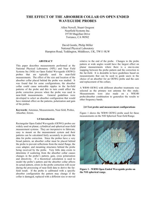
THE EFFECT OF THE ABSORBER COLLAR ON OPEN ENDEDWAVEGUIDE PROBESAllen Newell, Stuart Gregs<strong>on</strong>Nearfield Systems Inc.19730 Magellan DriveTorrance, CA 90502David Gentle, Philip MillerNati<strong>on</strong>al Physical LaboratoryHampt<strong>on</strong> Road, Teddingt<strong>on</strong>, Middlesex, UK, TW11 0LWABSTRACTThis paper describes measurements performed at <str<strong>on</strong>g>the</str<strong>on</strong>g>Nati<strong>on</strong>al Physical Laboratory (NPL) and Near FieldSystems Inc (NSI) <strong>on</strong> Open Ended Waveguide (OEWG)<strong>probes</strong> that are typically used for near-fieldmeasurements. The <str<strong>on</strong>g>effect</str<strong>on</strong>g> <str<strong>on</strong>g>of</str<strong>on</strong>g> <str<strong>on</strong>g>the</str<strong>on</strong>g> size and locati<strong>on</strong> <str<strong>on</strong>g>of</str<strong>on</strong>g> <str<strong>on</strong>g>the</str<strong>on</strong>g><str<strong>on</strong>g>absorber</str<strong>on</strong>g> <str<strong>on</strong>g>collar</str<strong>on</strong>g> placed behind <str<strong>on</strong>g>the</str<strong>on</strong>g> probe was studied. Itwas found that for some c<strong>on</strong>figurati<strong>on</strong>s, <str<strong>on</strong>g>the</str<strong>on</strong>g> <str<strong>on</strong>g>absorber</str<strong>on</strong>g><str<strong>on</strong>g>collar</str<strong>on</strong>g> could cause noticeable ripples in <str<strong>on</strong>g>the</str<strong>on</strong>g> far-fieldpatterns <str<strong>on</strong>g>of</str<strong>on</strong>g> <str<strong>on</strong>g>the</str<strong>on</strong>g> probe and this in turn could affect <str<strong>on</strong>g>the</str<strong>on</strong>g>probe correcti<strong>on</strong> process when <str<strong>on</strong>g>the</str<strong>on</strong>g> probe was used innear-field measurements. General guidelines weredeveloped to select an <str<strong>on</strong>g>absorber</str<strong>on</strong>g> c<strong>on</strong>figurati<strong>on</strong> that wouldhave minimal <str<strong>on</strong>g>effect</str<strong>on</strong>g> <strong>on</strong> <str<strong>on</strong>g>the</str<strong>on</strong>g> patterns, polarizati<strong>on</strong> and gain<str<strong>on</strong>g>of</str<strong>on</strong>g> <str<strong>on</strong>g>the</str<strong>on</strong>g> <strong>probes</strong>.Keywords: Antennas, Measurements, Near-field, Probes,Absorber, Errors.1.0 Introducti<strong>on</strong>Rectangular Open Ended Waveguide (OEWG) <strong>probes</strong> arewidely used <strong>on</strong> planar, cylindrical and spherical near-fieldmeasurement systems. They are inexpensive to fabricate,easy to mount <strong>on</strong> <str<strong>on</strong>g>the</str<strong>on</strong>g> measurement system and <str<strong>on</strong>g>the</str<strong>on</strong>g>irpatterns can be calculated fairly accurately to provide <str<strong>on</strong>g>the</str<strong>on</strong>g>data for probe correcti<strong>on</strong>. Since <str<strong>on</strong>g>the</str<strong>on</strong>g> <strong>probes</strong> have a verybroad pattern, an <str<strong>on</strong>g>absorber</str<strong>on</strong>g> <str<strong>on</strong>g>collar</str<strong>on</strong>g> must be placed behind<str<strong>on</strong>g>the</str<strong>on</strong>g> probe to prevent reflecti<strong>on</strong>s from <str<strong>on</strong>g>the</str<strong>on</strong>g> metal flange, <str<strong>on</strong>g>the</str<strong>on</strong>g>coax adapter, and mounting structures behind <str<strong>on</strong>g>the</str<strong>on</strong>g> probebeing received by <str<strong>on</strong>g>the</str<strong>on</strong>g> probe. Very little data exists todetermine if scattering from <str<strong>on</strong>g>the</str<strong>on</strong>g> <str<strong>on</strong>g>absorber</str<strong>on</strong>g> <str<strong>on</strong>g>collar</str<strong>on</strong>g> causeschanges in <str<strong>on</strong>g>the</str<strong>on</strong>g> probe’s pattern, gain, cross polarizati<strong>on</strong>and directivity. If a <str<strong>on</strong>g>the</str<strong>on</strong>g>oretical calculati<strong>on</strong> is used tomodel <str<strong>on</strong>g>the</str<strong>on</strong>g> probe’s pattern and <str<strong>on</strong>g>the</str<strong>on</strong>g> <str<strong>on</strong>g>absorber</str<strong>on</strong>g> <str<strong>on</strong>g>collar</str<strong>on</strong>g> affectsits actual pattern, errors in <str<strong>on</strong>g>the</str<strong>on</strong>g> probe correcti<strong>on</strong> will occurduring <str<strong>on</strong>g>the</str<strong>on</strong>g> processing <str<strong>on</strong>g>of</str<strong>on</strong>g> near-field data to derive <str<strong>on</strong>g>the</str<strong>on</strong>g> farfieldresult. If <str<strong>on</strong>g>the</str<strong>on</strong>g> probe is calibrated with a specific<str<strong>on</strong>g>absorber</str<strong>on</strong>g> c<strong>on</strong>figurati<strong>on</strong> <str<strong>on</strong>g>the</str<strong>on</strong>g> pattern may change if <str<strong>on</strong>g>the</str<strong>on</strong>g><str<strong>on</strong>g>collar</str<strong>on</strong>g> is damaged, replaced with a different size or movedrelative to <str<strong>on</strong>g>the</str<strong>on</strong>g> end <str<strong>on</strong>g>of</str<strong>on</strong>g> <str<strong>on</strong>g>the</str<strong>on</strong>g> probe. Changes to <str<strong>on</strong>g>the</str<strong>on</strong>g> probepattern at wide angles would have <str<strong>on</strong>g>the</str<strong>on</strong>g> largest <str<strong>on</strong>g>effect</str<strong>on</strong>g> <strong>on</strong>planar measurements where <str<strong>on</strong>g>the</str<strong>on</strong>g>re is a <strong>on</strong>e-to-<strong>on</strong>emapping between <str<strong>on</strong>g>the</str<strong>on</strong>g> probe pattern and <str<strong>on</strong>g>the</str<strong>on</strong>g> correcti<strong>on</strong> to<str<strong>on</strong>g>the</str<strong>on</strong>g> far-field. It is desirable to have guidelines based <strong>on</strong>measurements that can be used to guide users in <str<strong>on</strong>g>the</str<strong>on</strong>g>choice <str<strong>on</strong>g>of</str<strong>on</strong>g> an <str<strong>on</strong>g>absorber</str<strong>on</strong>g> for an OEWG probe and <str<strong>on</strong>g>the</str<strong>on</strong>g> careand replacement <str<strong>on</strong>g>of</str<strong>on</strong>g> <str<strong>on</strong>g>the</str<strong>on</strong>g> <str<strong>on</strong>g>collar</str<strong>on</strong>g>s.A WR90 OEWG with different <str<strong>on</strong>g>absorber</str<strong>on</strong>g> treatments wasselected as <str<strong>on</strong>g>the</str<strong>on</strong>g> primary test antenna for this study.Measurements were also made <strong>on</strong> a WR340probe/<str<strong>on</strong>g>absorber</str<strong>on</strong>g> combinati<strong>on</strong> to generalize <str<strong>on</strong>g>the</str<strong>on</strong>g> results too<str<strong>on</strong>g>the</str<strong>on</strong>g>r frequency bands.2.0 Test probe and measurement c<strong>on</strong>figurati<strong>on</strong>sFigure 1 shows <str<strong>on</strong>g>the</str<strong>on</strong>g> WR90 OEWG probe used for <str<strong>on</strong>g>the</str<strong>on</strong>g>semeasurements <strong>on</strong> <str<strong>on</strong>g>the</str<strong>on</strong>g> NSI Spherical Near-field Range.Figure 1 - WR90 Open Ended Waveguide probe <strong>on</strong><str<strong>on</strong>g>the</str<strong>on</strong>g> NSI spherical range.
The probe is 6” l<strong>on</strong>g and has a <str<strong>on</strong>g>collar</str<strong>on</strong>g> that is 12” squarec<strong>on</strong>structed from 3” pyramidal <str<strong>on</strong>g>absorber</str<strong>on</strong>g>. This is <str<strong>on</strong>g>the</str<strong>on</strong>g>standard c<strong>on</strong>figurati<strong>on</strong> for <str<strong>on</strong>g>the</str<strong>on</strong>g> NSI <strong>probes</strong> used <strong>on</strong> mostplanar, cylindrical and spherical ranges. On some rangesor for some mounting c<strong>on</strong>figurati<strong>on</strong>s a larger <str<strong>on</strong>g>absorber</str<strong>on</strong>g><str<strong>on</strong>g>collar</str<strong>on</strong>g> may be used and Figure 2 shows <str<strong>on</strong>g>the</str<strong>on</strong>g> same probewith a 24” X 24” in <str<strong>on</strong>g>collar</str<strong>on</strong>g> also using <str<strong>on</strong>g>the</str<strong>on</strong>g> 3”pyramidal<str<strong>on</strong>g>absorber</str<strong>on</strong>g>Figure 2 - WR90 OEWG probe with 24 X24 in<str<strong>on</strong>g>absorber</str<strong>on</strong>g> <str<strong>on</strong>g>collar</str<strong>on</strong>g>.A WR90 probe with <str<strong>on</strong>g>the</str<strong>on</strong>g> larger <str<strong>on</strong>g>absorber</str<strong>on</strong>g> <str<strong>on</strong>g>collar</str<strong>on</strong>g> wascalibrated at <str<strong>on</strong>g>the</str<strong>on</strong>g> Nati<strong>on</strong>al Physical Laboratory for an NSIcustomer using a spherical near-field/far-field range. Theresults <str<strong>on</strong>g>of</str<strong>on</strong>g> <str<strong>on</strong>g>the</str<strong>on</strong>g>se measurements showed significant ripples<strong>on</strong> <str<strong>on</strong>g>the</str<strong>on</strong>g> E-plane pattern and fur<str<strong>on</strong>g>the</str<strong>on</strong>g>r measurementsindicated that <str<strong>on</strong>g>the</str<strong>on</strong>g> <str<strong>on</strong>g>absorber</str<strong>on</strong>g> <str<strong>on</strong>g>collar</str<strong>on</strong>g> was <str<strong>on</strong>g>the</str<strong>on</strong>g> cause <str<strong>on</strong>g>of</str<strong>on</strong>g> <str<strong>on</strong>g>the</str<strong>on</strong>g>ripples.Figure 3 shows <str<strong>on</strong>g>the</str<strong>on</strong>g> E-plane patterns for different <str<strong>on</strong>g>absorber</str<strong>on</strong>g>sizes and orientati<strong>on</strong>s from <str<strong>on</strong>g>the</str<strong>on</strong>g> NPL measurements.Power (dB)10-1-2-3-4-5-6E-Plane, Freq 8.9 GHzER1F1ER1F2ER2F1ER3F1ER3F2ER3F3-80 -60 -40 -20 0 20 40 60 80θ °Figure 3 - WR90 OEWG E-plane pattern results fromNPL measurements.Key to Far-Field PlotsER1F1ER1F2ER2F1ER3F1ER3F2ER3F324” square x 3” with small stand<str<strong>on</strong>g>of</str<strong>on</strong>g>f24” square x 3” with small stand<str<strong>on</strong>g>of</str<strong>on</strong>g>f, extra<str<strong>on</strong>g>absorber</str<strong>on</strong>g> around probe/<str<strong>on</strong>g>absorber</str<strong>on</strong>g> interface24” square x 3” “ with no stand<str<strong>on</strong>g>of</str<strong>on</strong>g>f24”square x 4”24” square x 4” rotated 45 degrees aboutprobe axis24” square x 4” extra <str<strong>on</strong>g>absorber</str<strong>on</strong>g> aroundprobe/<str<strong>on</strong>g>absorber</str<strong>on</strong>g> interface no rotati<strong>on</strong>Table 1 - Absorber c<strong>on</strong>figurati<strong>on</strong>s tested at NPLshowing <str<strong>on</strong>g>absorber</str<strong>on</strong>g> width, thickness, orientati<strong>on</strong>positi<strong>on</strong> and modificati<strong>on</strong>s.The results from <str<strong>on</strong>g>the</str<strong>on</strong>g> NPL testing clearly show that <str<strong>on</strong>g>the</str<strong>on</strong>g>pattern is affected by <str<strong>on</strong>g>the</str<strong>on</strong>g> c<strong>on</strong>figurati<strong>on</strong> <str<strong>on</strong>g>of</str<strong>on</strong>g> <str<strong>on</strong>g>the</str<strong>on</strong>g> <str<strong>on</strong>g>absorber</str<strong>on</strong>g><str<strong>on</strong>g>collar</str<strong>on</strong>g> and in some cases <str<strong>on</strong>g>the</str<strong>on</strong>g>re were ripples <str<strong>on</strong>g>of</str<strong>on</strong>g> more than 1dB peak-to-peak for <str<strong>on</strong>g>of</str<strong>on</strong>g>f-axis angle <str<strong>on</strong>g>of</str<strong>on</strong>g> 60 degrees orgreater.To investigate this in more detail, <str<strong>on</strong>g>the</str<strong>on</strong>g> 6” l<strong>on</strong>g WR90OEWG probe shown in Figures 1 and 2 was installed <strong>on</strong><str<strong>on</strong>g>the</str<strong>on</strong>g> NSI spherical near-field range as <str<strong>on</strong>g>the</str<strong>on</strong>g> Antenna UnderTest (AUT). A WR90 Standard Gain Horn was used as<str<strong>on</strong>g>the</str<strong>on</strong>g> “probe” for <str<strong>on</strong>g>the</str<strong>on</strong>g>se measurements to reduce <str<strong>on</strong>g>the</str<strong>on</strong>g> <str<strong>on</strong>g>effect</str<strong>on</strong>g><str<strong>on</strong>g>of</str<strong>on</strong>g> chamber scattering. The measurement radius <str<strong>on</strong>g>of</str<strong>on</strong>g> 118”and <str<strong>on</strong>g>the</str<strong>on</strong>g> small aperture <str<strong>on</strong>g>of</str<strong>on</strong>g> <str<strong>on</strong>g>the</str<strong>on</strong>g> OEWG mean that this isessentially a far-field measurement and so <str<strong>on</strong>g>the</str<strong>on</strong>g> SGH probedoes not produce any probe correcti<strong>on</strong> <str<strong>on</strong>g>effect</str<strong>on</strong>g>. The datawas collected using <str<strong>on</strong>g>the</str<strong>on</strong>g> near-field measurement opti<strong>on</strong>and <str<strong>on</strong>g>the</str<strong>on</strong>g> far-field patterns were computed using <str<strong>on</strong>g>the</str<strong>on</strong>g>spherical near-to-far-field transformati<strong>on</strong>. This opti<strong>on</strong>made it possible to evaluate <str<strong>on</strong>g>the</str<strong>on</strong>g> chamber scattering <str<strong>on</strong>g>effect</str<strong>on</strong>g>sand o<str<strong>on</strong>g>the</str<strong>on</strong>g>r range related limitati<strong>on</strong>s and correct for <str<strong>on</strong>g>the</str<strong>on</strong>g>sewith <str<strong>on</strong>g>the</str<strong>on</strong>g> MARS[1] processing if necessary.Initial tests showed that <str<strong>on</strong>g>the</str<strong>on</strong>g> scattered signals in <str<strong>on</strong>g>the</str<strong>on</strong>g>chamber were approximately 30 dB below <str<strong>on</strong>g>the</str<strong>on</strong>g> peak <strong>on</strong>axissignal and produced a high frequency variati<strong>on</strong> <strong>on</strong><str<strong>on</strong>g>the</str<strong>on</strong>g> order <str<strong>on</strong>g>of</str<strong>on</strong>g> 0.2 dB <strong>on</strong> <str<strong>on</strong>g>the</str<strong>on</strong>g> E-plane pattern. These couldbe distinguished from <str<strong>on</strong>g>the</str<strong>on</strong>g> lower frequency variati<strong>on</strong>s <strong>on</strong><str<strong>on</strong>g>the</str<strong>on</strong>g> order <str<strong>on</strong>g>of</str<strong>on</strong>g> 1 dB that were produced by <str<strong>on</strong>g>the</str<strong>on</strong>g> <str<strong>on</strong>g>absorber</str<strong>on</strong>g><str<strong>on</strong>g>collar</str<strong>on</strong>g>.3. Measurement Results <strong>on</strong> WR90 OEWG withDifferent Absorber Collars
The WR90 OEWG probe was measured with <str<strong>on</strong>g>absorber</str<strong>on</strong>g><str<strong>on</strong>g>collar</str<strong>on</strong>g>s c<strong>on</strong>structed from 3”pyramidal <str<strong>on</strong>g>absorber</str<strong>on</strong>g> <str<strong>on</strong>g>of</str<strong>on</strong>g> 12 insquare and 24” square. Five inch <str<strong>on</strong>g>absorber</str<strong>on</strong>g> was used for a24” square <str<strong>on</strong>g>collar</str<strong>on</strong>g> and 1”flat <str<strong>on</strong>g>absorber</str<strong>on</strong>g> was used for a 24”square <str<strong>on</strong>g>collar</str<strong>on</strong>g>. Very little ripple was observed <strong>on</strong> <str<strong>on</strong>g>the</str<strong>on</strong>g>patterns with <str<strong>on</strong>g>the</str<strong>on</strong>g> smaller 12” square <str<strong>on</strong>g>collar</str<strong>on</strong>g> using <str<strong>on</strong>g>the</str<strong>on</strong>g>3”<str<strong>on</strong>g>absorber</str<strong>on</strong>g> and so we used this as <str<strong>on</strong>g>the</str<strong>on</strong>g> reference and <str<strong>on</strong>g>the</str<strong>on</strong>g>o<str<strong>on</strong>g>the</str<strong>on</strong>g>r results are shown compared to this c<strong>on</strong>figurati<strong>on</strong> in<str<strong>on</strong>g>the</str<strong>on</strong>g> following figures.012 in X 12 in Collar <str<strong>on</strong>g>of</str<strong>on</strong>g> 3 in Absorber24 in X 24 in Collar <str<strong>on</strong>g>of</str<strong>on</strong>g> 3 in AbsorberAmplitude in dB0-2-412 in X 12 in Collar <str<strong>on</strong>g>of</str<strong>on</strong>g> 3 in Absorber24 in X 24 in Collar <str<strong>on</strong>g>of</str<strong>on</strong>g> 5 in Absorber-2-6Amplitude in dB-4-90 -60 -30 0 30 60 90Azimuth Angle in DegreesFigure 5 - E-Plane patterns for WR90 OEWG with3”and 5”<str<strong>on</strong>g>absorber</str<strong>on</strong>g> <str<strong>on</strong>g>collar</str<strong>on</strong>g>s.-6012 in X 12 in Collar <str<strong>on</strong>g>of</str<strong>on</strong>g> 3 in Absorber24 in X 24 in Collar <str<strong>on</strong>g>of</str<strong>on</strong>g> 1 in Flat Absorber-90 -60 -30 0 30 60 90Azimuth Angle in DegreesFigure 4 - E-Plane patterns for WR90 OEWG withdifferent <str<strong>on</strong>g>absorber</str<strong>on</strong>g> <str<strong>on</strong>g>collar</str<strong>on</strong>g>s.Amplitude in dB-2-4-6-90 -60 -30 0 30 60 90Azimuth Angle in DegreesFigure 6 - E-Plane patterns for WR90 OEWG with 3in pyramidal and 1” flat <str<strong>on</strong>g>absorber</str<strong>on</strong>g> <str<strong>on</strong>g>collar</str<strong>on</strong>g>s.
OEWG ProbeAbsorber Shadow Angledirect gain measurement and <str<strong>on</strong>g>the</str<strong>on</strong>g> <str<strong>on</strong>g>collar</str<strong>on</strong>g> had been movedor changed after it was calibrated. The potential <str<strong>on</strong>g>effect</str<strong>on</strong>g> <strong>on</strong>gain can be inferred from <str<strong>on</strong>g>the</str<strong>on</strong>g> pattern measurements byexamining <str<strong>on</strong>g>the</str<strong>on</strong>g> pattern in <str<strong>on</strong>g>the</str<strong>on</strong>g> <strong>on</strong>-axis regi<strong>on</strong> and lookingfor small ripples in this regi<strong>on</strong>. Figure 8 shows <str<strong>on</strong>g>the</str<strong>on</strong>g>comparis<strong>on</strong> between <str<strong>on</strong>g>the</str<strong>on</strong>g> 12” and 24” <str<strong>on</strong>g>collar</str<strong>on</strong>g>s at 10 GHzfor <str<strong>on</strong>g>the</str<strong>on</strong>g> WR90 probe. Similar <str<strong>on</strong>g>effect</str<strong>on</strong>g>s were observed ato<str<strong>on</strong>g>the</str<strong>on</strong>g>r frequencies. From <str<strong>on</strong>g>the</str<strong>on</strong>g>se we c<strong>on</strong>clude that if <str<strong>on</strong>g>the</str<strong>on</strong>g>shadow angle shown in Figure 7 is less than 120 degrees,<str<strong>on</strong>g>the</str<strong>on</strong>g> <str<strong>on</strong>g>absorber</str<strong>on</strong>g> <str<strong>on</strong>g>collar</str<strong>on</strong>g> can cause gain variati<strong>on</strong>s <strong>on</strong> <str<strong>on</strong>g>the</str<strong>on</strong>g> order<str<strong>on</strong>g>of</str<strong>on</strong>g> 0.1 dB, which are undesirable, so this reinforces ourc<strong>on</strong>clusi<strong>on</strong> that <str<strong>on</strong>g>the</str<strong>on</strong>g> “<str<strong>on</strong>g>absorber</str<strong>on</strong>g> shadow angle” should begreater than 120 degrees.Absorber CollarWR90 OEWG Probe, 3 in Absorber Collars0.0012 in 24 in-0.05-0.10Figure 7 - Schematic showing <str<strong>on</strong>g>the</str<strong>on</strong>g> angular regi<strong>on</strong>shadowed by <str<strong>on</strong>g>the</str<strong>on</strong>g> <str<strong>on</strong>g>absorber</str<strong>on</strong>g> <str<strong>on</strong>g>collar</str<strong>on</strong>g>.These results are c<strong>on</strong>sistent with <str<strong>on</strong>g>the</str<strong>on</strong>g> NPL measurementsand verify that <str<strong>on</strong>g>the</str<strong>on</strong>g> <str<strong>on</strong>g>absorber</str<strong>on</strong>g> <str<strong>on</strong>g>collar</str<strong>on</strong>g> can produce significantripples <strong>on</strong> <str<strong>on</strong>g>the</str<strong>on</strong>g> E-plane pattern. From <str<strong>on</strong>g>the</str<strong>on</strong>g>se combinedmeasurements it has been determined that <str<strong>on</strong>g>the</str<strong>on</strong>g> <str<strong>on</strong>g>absorber</str<strong>on</strong>g><str<strong>on</strong>g>collar</str<strong>on</strong>g> will have minimal <str<strong>on</strong>g>effect</str<strong>on</strong>g> <strong>on</strong> <str<strong>on</strong>g>the</str<strong>on</strong>g> probe pattern if <str<strong>on</strong>g>the</str<strong>on</strong>g>“<str<strong>on</strong>g>absorber</str<strong>on</strong>g> shadow angle” shown in Figure 7 is at least120 degrees.In additi<strong>on</strong> to <str<strong>on</strong>g>the</str<strong>on</strong>g> measurements <strong>on</strong> <str<strong>on</strong>g>the</str<strong>on</strong>g> WR90 probe,similar measurements were performed <strong>on</strong> a WR340OEWG probe with different <str<strong>on</strong>g>absorber</str<strong>on</strong>g> <str<strong>on</strong>g>collar</str<strong>on</strong>g>s. Thesemeasurements also c<strong>on</strong>firmed <str<strong>on</strong>g>the</str<strong>on</strong>g> c<strong>on</strong>clusi<strong>on</strong>s from <str<strong>on</strong>g>the</str<strong>on</strong>g>initial measurements.4. Absorber Affect <strong>on</strong> GainThe <str<strong>on</strong>g>absorber</str<strong>on</strong>g> <str<strong>on</strong>g>collar</str<strong>on</strong>g> could possibly affect <str<strong>on</strong>g>the</str<strong>on</strong>g> <strong>on</strong>-axis gainas well as <str<strong>on</strong>g>the</str<strong>on</strong>g> pattern <str<strong>on</strong>g>of</str<strong>on</strong>g> <str<strong>on</strong>g>the</str<strong>on</strong>g> probe. This would notproduce errors for comparis<strong>on</strong> gain measurements where<str<strong>on</strong>g>the</str<strong>on</strong>g> same probe/<str<strong>on</strong>g>absorber</str<strong>on</strong>g> c<strong>on</strong>figurati<strong>on</strong> was used for both<str<strong>on</strong>g>the</str<strong>on</strong>g> gain standard and <str<strong>on</strong>g>the</str<strong>on</strong>g> AUT. But this would causeproblems if <str<strong>on</strong>g>the</str<strong>on</strong>g> probe is used as <str<strong>on</strong>g>the</str<strong>on</strong>g> gain standard in aAmplitude (dB)-0.15-0.20-0.25-0.30-15 -10 -5 0 5 10 15Azimuth (deg)Figure 8- Pattern ripples in <str<strong>on</strong>g>the</str<strong>on</strong>g> <strong>on</strong>-axis regi<strong>on</strong> causedby <str<strong>on</strong>g>the</str<strong>on</strong>g> <str<strong>on</strong>g>absorber</str<strong>on</strong>g> <str<strong>on</strong>g>collar</str<strong>on</strong>g>.5. SummaryMeasurements have shown that <str<strong>on</strong>g>the</str<strong>on</strong>g> <str<strong>on</strong>g>absorber</str<strong>on</strong>g> <str<strong>on</strong>g>collar</str<strong>on</strong>g> usedwith Open Ended Waveguide <strong>probes</strong> can have asignificant <str<strong>on</strong>g>effect</str<strong>on</strong>g> <strong>on</strong> both <str<strong>on</strong>g>the</str<strong>on</strong>g> pattern and <strong>on</strong>-axis gain.To minimize <str<strong>on</strong>g>the</str<strong>on</strong>g> <str<strong>on</strong>g>effect</str<strong>on</strong>g> <str<strong>on</strong>g>of</str<strong>on</strong>g> <str<strong>on</strong>g>the</str<strong>on</strong>g> <str<strong>on</strong>g>collar</str<strong>on</strong>g>, <str<strong>on</strong>g>the</str<strong>on</strong>g> angle between<str<strong>on</strong>g>the</str<strong>on</strong>g> end <str<strong>on</strong>g>of</str<strong>on</strong>g> <str<strong>on</strong>g>the</str<strong>on</strong>g> probe and <str<strong>on</strong>g>the</str<strong>on</strong>g> edge <str<strong>on</strong>g>of</str<strong>on</strong>g> <str<strong>on</strong>g>the</str<strong>on</strong>g> <str<strong>on</strong>g>absorber</str<strong>on</strong>g> shouldbe equal to or greater than 120 degrees. These resultsalso dem<strong>on</strong>strate that <str<strong>on</strong>g>the</str<strong>on</strong>g> <str<strong>on</strong>g>absorber</str<strong>on</strong>g> <str<strong>on</strong>g>collar</str<strong>on</strong>g> c<strong>on</strong>figurati<strong>on</strong>should not be changed after calibrati<strong>on</strong> and extra careshould be taken when handling <strong>probes</strong> and <str<strong>on</strong>g>the</str<strong>on</strong>g>ir<str<strong>on</strong>g>absorber</str<strong>on</strong>g> <str<strong>on</strong>g>collar</str<strong>on</strong>g>s.
6. References[1] Hindman, G, Newell, A.C., “Reflecti<strong>on</strong> Suppressi<strong>on</strong>in a large spherical near-field range”, AMTA 27 thAnnual Meeting & Symposium, Newport, RI, Oct. 2005.


