Oakton StableTemp Baths Manual
Oakton StableTemp Baths Manual
Oakton StableTemp Baths Manual
- No tags were found...

You also want an ePaper? Increase the reach of your titles
YUMPU automatically turns print PDFs into web optimized ePapers that Google loves.
heating11. WarrantyOPERATING INSTRUCTIONS12500-seriesOAKTON warrants this bath to be free from significant deviations in materialand workmanship for a period of one year from date of purchase (digital models12501-00 to -25) or five years from date of purchase (analog models 12500-00 to -35).If repair or adjustment is necessary and has not been the result of abuse or misusewithin the warrantied time period, please return—freight prepaid—and correctionwill be made without charge. OAKTON alone will determine if the product problemis due to deviations or customer misuse.Out-of-warranty products will be repaired on a charge basis.High PerformanceUtility <strong>Baths</strong>12. Return of itemsAuthorization must be obtained from our Customer Service Department beforereturning items for any reason. When applying for authorization, please includedata regarding the reason the items are to be returned. For your protection, itemsmust be carefully packed to prevent damage in shipment and insured against possibledamage or loss. We will not be responsible for damage resulting from careless orinsufficient packing. A restocking charge will be made on all unauthorized returns.NOTE: We reserve the right to make improvements in design, construction, andappearance of products without notice.Printed in the U.S.A. 5/01www.4oakton.com
Table of Contents1.0 Introduction .....................................................................................................................42.0 Receiving and Inspection .............................................................................................42.1 Inspection .......................................................................................................................42.2 Accessories .....................................................................................................................43.0 Installation ...................................................................................................................5-63.1 Power Source .................................................................................................................53.2 Location ..........................................................................................................................53.3 Lifting / Handling ........................................................................................................53.4 Bath Cover .....................................................................................................................53.5 Cleaning .........................................................................................................................64.0 Control Panel Overview (Analog Models 12500-00 to 12500-35)............................74.1 Power ..............................................................................................................................74.2 Temperature Controller................................................................................................74.3 Heating Indicator ..........................................................................................................75.0 Control Panel Overview (Digital Models 12501-00 to 12501-25).........................8-95.1 Power Switch .................................................................................................................85.2 Main Temperature Controller......................................................................................85.3 Heating Indicator ..........................................................................................................85.4 Overtemperature Safety Controller............................................................................85.5 Safety Indicator..............................................................................................................96.0 Operation...................................................................................................................10-126.1 Analog Models 12500-00 through 12500-35 .......................................................10-116.2 Digital Models 12501-00 through 12501-25........................................................11-127.0 Maintenance...................................................................................................................137.1 Cleaning........................................................................................................................137.2 Heating Elements ........................................................................................................138.0 Troubleshooting.......................................................................................................14-168.1 Temperature............................................................................................................14-158.2 Mechanical ...................................................................................................................168.3 Other .............................................................................................................................169.0 Parts.................................................................................................................................1710.0 Specifications..............................................................................................................1811.0 Wiring Diagrams ..................................................................................................19-2012.0 Warranty.......................................................................................................................2413.0 Return of Items...........................................................................................................242 3
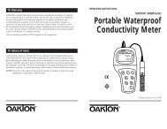
1. IntroductionThank you for purchasing an OAKTON ® <strong>StableTemp</strong> ® Bath. These units are generalpurpose water baths for professional, industrial or educational use where the preparationor testing of materials is done at approximately atmospheric pressure and noflammable, volatile, or combustible materials are being heated. These units are notintended for hazardous or household locations or use.Your satisfaction and safety require a complete understanding of this unit. Read theinstructions thoroughly and be sure all operators are given adequate training beforeattempting to put the unit in use. Note that this equipment must be used only for itsintended application; any alterations or modifications will void your warranty.See back page of this manual for more warranty information.2. Receiving and Inspection2.1InspectionThe carrier accepts responsibility for safe delivery and is liable for loss or damage.On delivery, inspect for visible exterior damage. Describe and note on the freight billany damage found on the shipping carton or unit and enter a claim on the form suppliedby the carrier.Inspect for concealed loss or damage on the unit itself. If any damage is found thecarrier will arrange for an official inspection to substantiate your claim.If for any reason you must return the unit, authorization must be obtained from ourCustomer Service Department. see the back page of this manual for more informationon return of items.2.2AccessoriesVerify that all of the equipment indicated on the packaging slip is included with theunit. Carefully check all packaging before discarding. All models include a stainlesssteel gable cover. Analog models 12500-00 through -35 also include a glass thermometerand thermometer clip.3. InstallationLocal city, county or other ordinances may govern the use of this equipment. If youhave any questions about local requirements, please contact the appropriate localagency. Installation may be performed by the end user. It is unnecessary for this unitto be installed by a technician.Under normal circumstances this unit is intended for use inside, at room temperaturesbetween 5°C and 40°C, at no greater than 80% relative humidity (at 25°C) andwith a supply voltage that does not vary by more than 10%. Customer Serviceshould be contacted for operating conditions outside of these limits.3.1Power SourceThe electrical supply to the unit must conform to all national and local electricalcodes. The power source must match the voltage and ampere requirements listedon the dataplate. Consult the units serial data plate for the voltage and ampererequirements before making connection. Plug the cord into a grounded outlet.The voltage of the outlet should not vary more than 10% from the dataplate rating.A separate circuit is recommended to preclude loss of product due to overloading orcircuit failure.3.2LocationWhen selecting a location for this unit, consider all conditions which might affectperformance, such as heat from radiators, ovens, autoclaves, etc. Avoid direct sun,fast-moving air currents, heating/cooling ducts and high-traffic areas. Allow aminimum of 5 cm between the unit and surrounding walls and partitions whichmight obstruct free air flow.3.3Lifting / HandlingThese units may be heavy for some people and care should be taken to use appropriatelifting devices that are sufficiently rated for these loads. Units should only belifted from their bottom surfaces. Handles and knobs are not adequate for lifting orstabilization. The unit should be completely restrained from tipping during liftingor transport. All moving parts, such as racks and covers should be removed anddoors need to be positively locked in the closed position during transfer to preventshifting and damage.3.4Gable CoverUsing the gable cover will accelerate heat-up time, ensure stability, and reduce evaporation.The cover must be used to reach set points above 60°C. Note that the coveris not designed to be air tight or create a pressurized environment.45
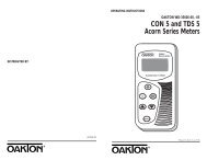
3.5CleaningThe water bath was cleaned at the factory, but not sterilized. It should be disinfectedprior to use. Clean the bath and rack assembly with a disinfectant that is appropriateto your application. DO NOT USE chlorine-based bleaches or abrasives asthis will damage the tank. DO NOT USE spray cleaners that might leak throughopenings and cracks and get on electrical parts or that may contain solvents thatwill harm the coatings. Similar periodic cleaning is recommended.WARNING: Never clean the unit with alcohol or flammable cleaners with the unitconnected to the electrical supply. Always disconnect the unit from the electricalservice when cleaning and assure all volatile or flammable cleaners are evaporatedand dry before reattaching the unit to the power supply.4.0 Control Panel Overview (Analog Models 12501-00 to 12500-35)Figure 1: Control panel, analog models 12500-00 to 12500-35temperatureheating4.1PowerThe main power I/O (on/off) switch controls all power to the bath. It must be in theI or ON position and illuminated before any systems are operational.4.2Temperature ControllerThis control is marked Temperature. It controls your selection of water bath operatingtemperature on a scale of 0 to 10. This scale does not represent temperature, butis to be used as a reference guide. The operating range is 5°C above ambient to100°C.4.3Heating IndicatorThis pilot lamp is marked Heating and is ON when the Main TemperatureController is energizing the heating element. The element will cycle on and off asneeded to maintain the set point temperature.67
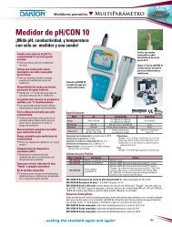
5.0 Control Panel Overview (Digital Models 12501-00 to 12501-25)Figure 2: Control panel, digital models 12501-00 to 12501-255.5Safety IndicatorThis pilot lamp marked Safety comes ON in the event that the operating temperatureexceeds the Main Temperature Controller set point and reaches the SafetyController set point. Note: under normal operating conditions this indicator shouldnever be on.5.1Power SwitchThe main power I/O (on/off) switch controls all power to the bath. It must be in theI or ON position and illuminated before any systems are operational.5.2Main Temperature ControllerThis controller is marked Temperature and consists of the digital display with▲ / ▼ (Up/Down) key pads for inputting set point temperatures and calibration.5.3Heating IndicatorThis pilot lamp is marked Heating and is ON when the Main TemperatureController is energizing the heating element. The element will cycle on and off asneeded to maintain the set point temperature.5.4Overtemperature Safety Control ThermostatThis is a hydraulic control with a remote sensor that is completely independent ofthe Main Temperature Controller. It is mounted on the control panel and markedSafety. The Safety Controller provides over-temperature protection in the unlikelyevent the Main Temperature Controller fails, and the temperature should rise pastthe set point. Temperature is then limited to the Safety set point.89
6. OperationWARNING: THESE BATHS ARE NOT INTENDED FOR USE AS ACID BATHS.USE AS AN ACID BATH WILL CAUSE SEVERE DAMAGE TO BATH COMPO-NENTS AND VOID YOUR WARRANTY. DO NOT USE DEIONIZED WATER,TAP WATER, OR CHEMICALS. USE DISTILLED WATER ONLY.6.1Analog Models 12500-00 through 12500-356.1.1 Power SupplyConnect the service cord to the grounded outlet and push the power switch to theON position. If supplied with a detachable cordset, plug the female end into theinlet of the unit and the male plug into the supply. Assure that units requiring afuse have a fuse installed. This fuse may be at the inlet part of the cordset maleplug.6.1.2 FillingFill bath to your required depth with distilled water only. DO NOT USE tap water.DO NOT USE deionized water. Note that normal depth is two-thirds full, butdepth must be at least 2 inches (5 cm).6.1.3 Insert Thermometer:Place thermometer in position as desired (a clip is provided with your accessorypackage). See Figure 3.Figure 3MagneticStripPinch clip to increasefriction and keepthermometer fromslidingThis clip can be mountedfrom any side of the bathThermometer bulb must not touch sides or bottom of the bathbut must be fully immersed. The location of the thermometermay be determined by the opening in the bath cover if used.6.1.4 Setting TemperatureTo set the Temperature Control, turn the knob clockwise to the maximum setting.The Heating light will glow indicating that the bath is heating. Allow the unit toheat until the reference thermometer has reached the desired temperature. Whenthe desired temperature has been reached, turn the control knob counterclockwisejust until the Heating light goes off. Allow the unit to stabilize for several hours.Re-adjust the control knob up or down as required until the desired temperature isobtained. Allow the unit to stabilize between each setting. Temperature stability isobtained when the Heating light is going on and off automatically and the temperaturevalue in the bath remains constant.6.2Digital Models 12501-00 through 12501-256.2.1 FillingFill the bath to the desired level with distilled water. DO NOT USE TAP WATEROR DEIONIZED WATER. The water depth must be at least 5 cm above the sensingprobe (which extends in to the tank) or unstable temperatures will occur.6.2.2 Power SupplyConnect the service cord to the grounded outlet and push the power switch to theON position. If supplied with a detachable cordset, plug the female end into theinlet of the unit and the male plug into the supply. Assure that units requiring afuse have a fuse installed. This fuse may be at the inlet part of the cordset maleplug.6.2.3 Safety Control ThermostatTurn the Safety Control clockwise to its maximum position. A coin or flatheadscrewdriver is necessary to turn the knob.6.2.4 Setting Temperature Controller:Enter desired set point temperature in °C. To enter set point mode on the Controller,press either the ▲ or ▼ (Up or Down) button once. The digital display will start toblink from bright to dim. While blinking, the digital display is showing the setpoint. To change the set point, use the ▲ and ▼ buttons. If the buttons are notpressed for five (5) seconds, the display will read the actual bath temperature. Allowthe bath at least two (2) hours to stabilize. NOTE: If operating the bath above 60°Cthe bath cover must be used to obtain temperature desired.10 11
6.2.5 Calibrating Temperature ControlWe recommend calibration of the bath once it is in its working environment and stabileat set point. Place a reference thermometer in the bath (there is a thermometerclip provided with your accessories package). See Figure 3 on page 10.Allow the thermometer to stabilize for at least one hour. Compare the reading onthe reference thermometer with the temperature control display. If there is a difference,put the display into calibrate mode by pressing both the ▲ or ▼ (Up or Down)arrow pads simultaneously until the two (2) outside decimal points begin to blink.When the display is blinking, press either the ▲ or ▼ arrow pads to adjust the displayto match the reference thermometer. If the arrow pads are not pressed withinfive (5) seconds the display will revert to the actual bath temperature. Allow the unitto restabilize, and repeat above if necessary.6.2.6 Setting Safety Control ThermostatAs mentioned in section 6.2.3, the Safety Thermostat should be initially set to itsmaximum position to allow the water bath to stabilize. Once the bath maintains theset point, turn the Safety Thermostat counterclockwise until the Safety Indicatorlight turns on. Then turn the Safety Thermostat clockwise slowly, until the safetyindicator light turns off. This will set the Safety Thermostat at approximately 1°Cabove the Temperature Control set point.7.0 MaintenanceNote: Prior to any maintenance or service on this unit, disconnect service cord fromthe electrical supply source.7.1CleaningClean the stainless steel tank with a mild soap and water solution. Rinse with cleanwater and wipe dry with soft cloth. Clean the outer surfaces with a damp spongeand wipe dry avoiding the electrical controls. Foreign material may cause small rustspots that show up in the bath. Remove these rust spots with a mild abrasive; neveruse steel wool. Failure to periodically polish out these rust spots may cause prematurefailure of the bath tank.7.2Heating elementsThe heating element of this bath does not contact the tank bottom, thus will notburn out if the tank is allowed to run dry; however, a tank going dry may straininterior surfaces so this should not be allowed to occur.WARNING: IF TANK BOILS DRY WHILE CONTAINING PLASTICWARE,THE PLASTIC WILL MELT. IF YOU INTEND TO USE TEST TUBE RACKS,REMEMBER THAT PLASTIC COATED WIRE RACKS MAY WEAR ANDEXPOSE METAL WHICH CAN CAUSE DAMAGE. PREFERABLY, USE ALLPLASTIC.12 13
8.0 Troubleshooting8.1TemperatureProblemTemperature too highDisplay reads "HI" or "400"+Temperature spikes overset point and then settlesto set pointTemperature too lowSolution1) Main controller set too high2) Main controller failed on – call Customer Service.3) Wiring error – call Customer Service.Probe is unplugged, is broken or wire to sensoris broken – call Customer ServiceRecalibrate1) Main controller set too low2) Bath temperature not recovered from waterbeing added – wait for display to stop changing.3) Unit not recovered from power failure or beingturned off – bath will need a minimum of2 hours to warm up and stabilize.4) Element failure; compare current draw todata plate.5) Main controller failure – confirm with front panellights that controller is calling for heat.6) Wiring problem; check all functions andcompare wiring to wiring schematicespecially around any areas recently worked on.7) Loose connection – call Customer Service.Display reads "LO" 1) Sensor is plugged in backwards –call Customer Service.2) If ambient temperature is lower than range of unit– compare set points and ambient temperature torated specifications in section 7.0,Unit Specifications.Unit will not heat over a 1) Confirm that amperage and voltage match datatemperature that isbelow set pointUnit will not heat up at allplate.2) Confirm that set point is set high enough.3) Check calibration – using independentthermometer, follow instructions in section 4.51) Check amperage – amperage should be virtuallyat maximum rated (data plate) amperage.2) Do all controller functions work?3) Has the fuse/circuit breaker blown?ProblemIndicated bath temperatureunstableWill not maintain set pointDisplay and Referencethermometer don’t matchCan't adjust set pointsor calibrationCalibrated at onetemperature, butnot at anotherSolution1) ±0.3 may be normal, especially without the useof bath cover.2) Is ambient room temperature radically changing– either door opening or room airflow fromheaters or air conditioning ? – stabilizeambient conditions.3) Calibration sensitivity – recalibrate.Call customer service if re-calibrationdoes not resolve fluctuation.4) Assure that the bath is at least one-third full.5) Electrical noise – remove nearby sources of RFIincluding motors, arcing relays or radiotransmitters.6) Bad connection on temperature sensor orfaulty sensor – call Customer Service.1) Assure that set point is at least 5 degrees aboveambient room temperature.2) See if ambient is fluctuating.1) Calibration error2) Temperature sensor failure; call Customer Service.3) Controller failure – call Customer Service.4) Allow at least two hours to stabilize.5) Verify that reference thermometer is certified.1) Turn entire unit off and on to reset.2) If repeatedly happens, call Customer Service.This can be a normal condition when operatingtemperature varies widely. For maximum accuracy,calibration should be done as close to the set pointtemperature as possible.14 15
8.2Mechanical9.0 PartsProblemSolutionWater leaking1) Dry bath and check the tank with flashlight tosee if leak is noticeable.2) Fill tank again and see if leak repeats and findsource of leak. Call Customer Service if continues.Holes or rust in 1) Assure that clean, distilled water is used –water bath tanksdeionized water, tap water and chemicals shouldnever be used in the tank. USE DISTILLEDWATER ONLY.2) Assure that no test sample has leaked intobath water.3) No metallic products should be in the tankwith exception of the polymer coated rack.8.3OtherProblemController on at all times-"locked-up"Front panel displaysare all offUnit or wall fuse/circuit breaker is blownUnit will not turn onUnit is smoking –out of boxSolution1) Turn unit off and on to reset.2) If cannot change any condition on the front panel,call Customer Service.Check for wire damage.1) Check wall power source.2) Compare current draw and compare to specson data plate.3) See what other loads are on the wall circuit.1) Check wall power source.2) Check fuse circuit breaker on unit or in wall.3) Check all wiring connections,esp. around the on/off switch.This is not an uncommon occurrence for new units.The elements will burn off protective coatings.Run the bath at high temperature for one houruntil smoke dissipates.Description 120 VAC 220 VACEMI Filter N/A 2800502Fuse, 6.3 Amp N/A 103555Heating Element 2350503 120071Pilot Lamp, Heating (green) 200021 200021Pilot Lamp, Safety (red) 200020 200020Power Cord 100014 104192Power Switch 103351 103351Safety Controller 100001 100001Temperature Controller w / Probe 1750564 1750565Gable for 5-L bath 12500-70Gable for 12-L bath 12500-71Gable for 20-L bath 12500-72Mercury-filled Glass Thermometer 01252-05Spirit-filled Glass Thermometer 93905-9116 17
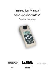
10.0 Specifications 11.0 Wiring DiagramsThese units are 100V or 220V. Please refer to the unit data plate for its individualspecifications.Analog Models12500-00, -05 12500-10, -15 12500-20, -25 12500-30, -35Capacity 2.25 L (0.59 gal) 5 L (1.32 gal) 12 L (3.17 gal) 20 L (5.28 gal)Temperature Range5° above ambient to 100°C (212°F)Temperature ControlOn/off hydraulic thermostatStability ±0.3°C at 37°C5.75" x 5.5" 11.5" x 5.875" 11.5" x 12.75" 11.5" x 19.5"Bath (W x H x D) x 6" (14.6 x x 6" (29.2 x x 6" (29.2 x x 6" (29.2 x14.0 x 15.2 cm) 14.9 x 15.2 cm) 32.4 x 15.2 cm) 49.5 x 15.2 cm)8.25" x 7.25" 14" x 9.5" 14" x 9.5" 14.75" x 9.5"Overall (W x H x D) x 10.75" (20.9 x x 12" (35.6 x x 18.75" (35.6 x x 24.5" (37.5 x18.4 x 27.3 cm) 24.1 x 30.5 cm) 24.1 x 47.6 cm) 24.1 x 62.2 cm)Shipping weight 16 lbs (7.3 kg) 23 lbs (10.5 kg) 31 lbs (14.1 kg) 37 lbs (16.8 kg)12500-00 THROUGH 12500-35CE approved units onlyPlug StylesNEMA 5-15P NEMA 6-15P EUI-16P UK-13PinletFilterFuseOn/Off switchDigital Models12501-00, -05 12501-10, -15 12501-20, -25Capacity 5 L (1.32 gal) 12 L (3.17 gal) 20 L (5.28 gal)Temperature Range5° above ambient to 100°C (212°F)Temperature ControlPID microprocessor, RTDStability ±0.20°C at 37°CBath (W x H x D)11.5" x 5.875" x 6" 11.5" x 12.75" x 6" 11.5" x 19.5" x 6"(29.2 x 14.9 x 15.2 cm) (29.2 x 32.4 x 15.2 cm) (29.2 x 49.5 x 15.2 cm)Overall (W x H x D)14" x 9.5" x 12" 14" x 9.5" x 18.75" 14.75" x 9.5" x 24.5"(35.6 x 24.1 x 30.5 cm) (35.6 x 24.1 x 47.6 cm) (37.5 x 24.1 x 62.2 cm)Shipping weight 23 lbs (10.5 kg) 31 lbs (14.1 kg) 37 lbs (16.8 kg)Regulating ThermostatHeating ElementLights while heating pilotPower on pilot18 19
12501-00 THROUGH 12501-25IEC 320Inlet withfuseEMI FilterCE modelsNEMA 5-15P NEMA 6-15P EUI-16P UK-13PPlug StylesUse cord adapter plate with bushinghole for domestic modelsFuse on domestic models may berequired or second fuse on DIN modelsPower on pilotSensing ProbeLoadGroundNeutralHotTemperature ControlSafety ControlSafety pilotHeat on PilotNote: this duplicate circuit for Model 1255 onlySensing ProbeLoadGroundNeutralHotTemperature ControlSafety ControlSafety pilotHeat on Pilot20 21
22 23