CS110 Electric Field Meter Overview - Campbell Scientific
CS110 Electric Field Meter Overview - Campbell Scientific
CS110 Electric Field Meter Overview - Campbell Scientific

You also want an ePaper? Increase the reach of your titles
YUMPU automatically turns print PDFs into web optimized ePapers that Google loves.
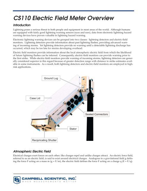
<strong>CS110</strong> <strong>Electric</strong> <strong>Field</strong> <strong>Meter</strong> <strong>Overview</strong>IntroductionLightning poses a serious threat to both people and equipment in most areas of the world. Although humansare equipped with fairly good lightning warning sensors (eyes and ears), data from electronic lightning hazardwarning devices have proven valuable in lightning hazard warning.Electronic lightning warning devices can be grouped into two classes: lightning detectors and electric-fieldmonitors. Lightning detectors provide information about past lightning flashes, providing advanced warningof incoming storms. Yet lightning detectors provide no warning until a detectable lightning discharge hasoccurred, which may be too late for storms developing overhead.<strong>Electric</strong> field monitors provide information about the local atmospheric electric field from which the likelihoodof future lightning flashes can be inferred. Consequently, electric-field monitors can provide warning prior tothe first strike. While electric-field monitors provide warning of incoming storms, lightning detectors are generallyconsidered superior in this regard because of greater detection range with distance to strike estimates availablein some instruments. As a result, both lightning detectors and electric-field monitors are employed in highriskapplications.Ground LugCase LidSealed ConnectorsStatorRecipricating ShutterAtmospheric <strong>Electric</strong> <strong>Field</strong><strong>Electric</strong>al charges exert forces on each other; like charges repel and unlike charges attract. An electric force field,referred to as an electric field, is said to exist around electrical charges. Analogous to a gravitational field g definingthe force F acting on a mass m (g = F/m), the electric field defines the force F acting on a charge q (E = F/q).CAMPBELL SCIENTIFIC, INC.W H E N M E A S U R E M E N T S M A T T E R®
The electric field E is a vector quantity, havingboth a magnitude (field strength) and direction(direction of force exerted on a positive testcharge). The units of electric field are Newtons/Coulomb, which are equivalent to the morecommonly expressed units of Volt/meter (V/m).The magnitude of the electric field is equivalentto the potential (voltage) gradient.Because large quantities of separated electricalcharges are associated with thunderstorms, thevertical component of atmospheric electric fieldE at the earth’s surface is useful for studyingelectrified clouds and for lightning warning.By convention, the sign of the electric field isconsidered positive (positive test charge wouldbe pulled upward) if the overhead charge is predominantlynegative, and defined as negative(positive test charge would move downward) ifoverhead charge is predominantly positive.On a clear day (fair weather), a relatively smallnumber of positive ions exist in the atmospherethat give rise to an electric field on the order of-100 to -200 V/m. These fair weather ions arethought to be generated by means of worldwidethunderstorms and distributed globally bythe conductive electrosphere. The local electricfield during a 24 hour fair weather period asmeasured with a <strong>CS110</strong> electric-field meter isillustrated in Figure. 2.Electrifi ed CloudFair WeatherFigure 1. Sign convention of electric field at the Earth’s surface.(a) Positive electric field induced by negative charge at the cloud base.(b) Negative electric field induced by positive ions in the fair weather conditions.Diurnal Fair Weather <strong>Electric</strong> <strong>Field</strong> at Logan, Utah on July 27, 2005(Mean Value =-75.1 Volt/meter, Mean Temperature = 68.8ºF)<strong>Electric</strong> <strong>Field</strong> (volt/meter)Solar Radiation (Watts per square meter)<strong>Electric</strong> <strong>Field</strong>Solar RadiationMountain Daylight Time (1 minute average of 1 second samples)Figure 2. <strong>Electric</strong>-<strong>Field</strong> Measured with <strong>CS110</strong> During 24 Hour Period of Fair Weather.2
The fair weather diurnal pattern is believed to be caused by variations in world-wide thunderstorm activitywhich affects a global electric circuit.The presence of charged clouds results in dramatic increases in the magnitude of the local electric field as comparedwith fair weather fields, with the sign indicating the dominating charge polarity. Figure 3 displays thelocal atmospheric electric during a local thunderstorm. Deviation from and return to fair weather field conditionsare observed at the beginning and end of this storm. The abrupt electric field change observed at approximately6:12 am was due to a cloud-to-ground lightning discharge within 1 mile of the electric-field meter.August 2, 2005 Thunderstorm at Logan Utah<strong>Electric</strong> <strong>Field</strong> (Volt/meter)Mountain Standard Time (1 sample per second)Figure 3. Atmospheric electric field monitored by a <strong>CS110</strong> during a local thunderstorm.Although no universal warning criteria based on electric-field measurements exists, two levels that have been usedare ⏐1000 V/m⏐ [LPLWS] and ≥⏐2000⏐ V/m [NAVSEA]. Obviously the lower the level used the more risk reductionavailable, at the expense of increased down time for operations suspended for lightning hazard warning.The <strong>CS110</strong> Versus Traditional <strong>Field</strong> MillsAtmospheric electric fields have been measured for decades by electric field meters dubbed “field mills”. Traditionalfield mills employ a continuously rotating vane (rotor) electrically connected to ground potential. Thegrounded spinning rotor alternately shields and exposes sense electrodes from the electric field to be measured,resulting in a modulation of induced electrical charge. A charge amplifier, or pair of charge amplifiers, convertthe modulated charge into an AC voltage. Further signal conditioning results in a low frequency (≤10 Hz) voltageproportional to the electric field.A variety of methods have been employed to make electrical contact with the spinning motor shaft of rotatingvane field mills, all of which suffer from wear out mechanisms. Furthermore, traditional field mills do not havean inherent way to compensate for electronic drift with time and temperature, along with changes in leakagecurrents across sense-electrode insulators, all of which induce measurement errors. Frequent scheduled cleaningof insulators is often necessary in critical field-mill applications, especially in coastal environments, to minimizemeasurement errors due to insulator leakage currents.3
Unlike traditional rotating vane field mills, the <strong>CS110</strong> uses a reciprocating shutter. A stepper motor opens andthen closes the reciprocating shutter by 45º during measurements. The reciprocating shutter is electrically connectedto ground potential by a flexible stainless steel strap operated below its fatigue limit, resulting in an ultrareliableelectrical ground connection. The stainless steel grounding strap and the motor assembly are illustratedin Figure 4; the 316-L stainless-steel electrodes and base plate are illustrated in Figure 5. An optical positionencoder is used to determine the position of the shutter.Grounding StrapPosition encoderStepper motorBase plateSense ElectrodeShutterFigure 4. <strong>CS110</strong> Motor AssemblyIn the reciprocating approach, low-frequency measurement errors associated with electronic drift and changinginsulator leakage currents are inherently compensated for by utilizing the zero electric-field reference availablewhen the shutter is closed.Traditional field mills typically consume many watts of power with their continuously operated motors. In thereciprocating approach, the stepper motor is powered off much of the time, resulting in low power consumptionand low noise. The current required by the reciprocating electric-field meter powered from 12 VDC is illustratedin Figure 6. As depicted in the figure, the average electric-field meter current is a function of the desired measurementrate, which is under user control.Variable sample rates based on measured results can be implemented to conserve power in solar powered applications.For example, the <strong>CS110</strong> can be programmed to measure electric field at a 10-second rate during fairweather conditions, and then automatically switch to faster measurements during threatening conditions.4
The reciprocating motion of the <strong>CS110</strong> electricfieldmeter is limited to approximately 5 Hz,which is adequate for lightning hazard warning,where 1 minute averaged data is oftenused. For applications desiring >5 Hz, the<strong>CS110</strong> reciprocating electric-field meter can beconfigured as a slow antenna (MacGorman andRust). The shutter would typically be left openindefinitely in slow antenna mode and a resistorelectronically switched into the charge amplifierproviding a 66 ms decay time constant. In theslow antenna mode, the <strong>CS110</strong> is a field changemeter with the charge amplifier having a highpassfilter frequency response with the lowercutoff frequency defined as f3dB = (2πR·C) -1 =2.4 Hz. In slow antenna mode the charge amplifieroutput can be sampled by the datalogger asfast as every 20 ms (50 Hz), using 250 µs integrationdurations for the analog integrator.The CR1000 datalogger embedded within each<strong>CS110</strong> can be used to extend the capability ofthe <strong>CS110</strong>. The CR1000 provides measurementand control functions, data processing and storage,a user interface language (CRBasic TM ), andflexible communications options. LoggerNet TMdatalogger support software (purchased separately)provides versatile networking and datacollection capabilities.ShutterSense electrodeTefl oninsulatorStatorFigure 5. <strong>CS110</strong> Polished 316-L Stainless Steel ElectrodesAverrage Current (mjA) @ 12 VMeasurement Interval (Seconds)Figure 6. <strong>CS110</strong> Average Current Consumption versus Measurement Interval5
The <strong>CS110</strong> interfaces to select <strong>Campbell</strong> <strong>Scientific</strong> meteorological sensors. Wind speed, wind direction, air temperature,relative humidity, rainfall, solar radiation and/or barometric pressure sensors interface directly to the<strong>CS110</strong>. This can result in an automated weather station that includes atmospheric electric-field data.ReferencesMETEOROLOCIAL\CCAFS\81900\LAUNCH PAD LIGHTNING WARNING SYSTEM (LPLWS) (www-sdd.fsl.noaa.gov/RSA/LPLWS_inst_handbook.pdf)NAVSEA OP 5, Vol 1, Seventh Rev. Para 6-2, pg 6-1 and 6-2, 2001.MacGorman D. R., and Rust W. D, The <strong>Electric</strong>al Nature of Storms, pp. 143-144, 1998.815 W. 1800 N. | Logan, Utah 84321-1784 | USA | phone (435) 753-2342 | www.campbellsci.comAustralia | Brazil | Canada | England | France | Germany | South Africa | Spain | USA [headquarters]Copyright © 2005, 2007<strong>Campbell</strong> <strong>Scientific</strong>, Inc.Printed January 2007