Download PDF - Voith Turbo
Download PDF - Voith Turbo
Download PDF - Voith Turbo
- No tags were found...

Create successful ePaper yourself
Turn your PDF publications into a flip-book with our unique Google optimized e-Paper software.
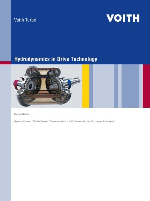
Hydrodynamics in Drive TechnologyHeinz HöllerSpecial Issue “<strong>Voith</strong> Power Transmission – 100 Years of the Föttinger Principle”
ContentsHydrodynamics in Drive Technology – A Short Introduction 4Development of <strong>Turbo</strong> Couplings and Converters 10Development Period Until 1949 11Development Period from 1950 to 1969 14Development Period After 1970 183
Hydrodynamics in Drive Technology –A Short IntroductionThis chapter provides a very concise introduction to the significance of hydrodynamiccomponents in drive technology. It is meant to familiarize the readerwith this fascinating technology.As soon as the first simple machines emerged in ancient history, there was aneed for adaptation or compensation in the power transmission process betweenthe driving power source and the driven machine or a certain operating procedure.The irrigation systems in ancient Egypt and medieval grist mills used waterwheels or windmills, while devices for lifting heavy loads or scooping water weremoved by draft animals.The operating process involved required that the speed of a driven machinewas either increased, decreased or diverted to the rotating axle to match theoutput of the driving machine. Simple mechanical transmissions appeared on thescene. The demand for further intermediate driving components started to grow.The necessity for installing an adapting component into the driveline alwaysremained, even when the modern driven machines of our time were introduced,for example steam engines, electric motors, combustion engines and steam orgas turbines. The questions raised in this context today are basically identical tothose asked in prehistoric times:– What is the operating process for which the drive is needed and howimportant is the process?– Which process quantities are to be influenced by the driven machine in whichway?– Which type of machine is to drive the process?– And finally, important for <strong>Voith</strong>: which characteristics of the driving and drivenmachine are unsuitable for the process and have to be compensated or adaptedby a hydrodynamic element in the driveline?Typical Processes and Their DrivesThe following three operating processes and three common driving machinesare used as an example of the wide range of possible applications in drive technology:4
Exploded view of the componentsof a converter (top), acoupling (middle) and a brake(bottom), with the powertransmitting volume flow inyellow. On the left a schematicand a symbolic illustration perVDI 2153.Converter:Torque and speed conversionM P + M T + M R = 0 T min P T maxCoupling:Speed conversion onlyM P = M T P TBrake:Converting mechanical energyinto heatM P = M T T = 0Pumps and turbines in hydrodynamic transmissions are fluid machines. Theirhydraulic output P h can generally be described on the basis of a formula developedby the Swiss mathematician Leonhard Euler:P h = ṁ . Δ (r . c u ) . ωT = TurbineP = Pump (impeller)R = Guide vane (stator)Which means:.m = Mass flowΔ (r . c u ) = Change of momentum between inlet and outlet of the flow gridω = Angular velocity of bladed wheelUsing the laws of fluid dynamics, a similar formula for the pump output P P canbe developed for practical use on the basis of the classic Euler formula:P P = λ . ρ . D P5 . ω P3 and M P = λ . ρ . D P5 . ω P2This means:D P = Outer diameter of pump profileρ = Density of operating fluidω P = Angular velocity of pump wheelM P = Pump torqueλ = Characteristic power figure (proportional figure)7
ConverterM T = M P + M L = M T / M PCharacteristic curvedevelopmentTurbine characteristicsHousingConverter typeM P0decreasing at ≈ 1centripetal flowrotatingTrilok1M P0fairly constantcentrifugal flowfixedFöttinger (Lysholm)1increasingM Paxial flowfixedcontra-rotating converter (DIWA)01CouplingM P0M T = M PM T01M PM T1Characteristic curveDevelopmentTurbine characteristicsHousingCoupling typecontinuously falling (full partly full )closed meridian flowrotatingFöttinger/Vulcanself-adjustingdeviating meridian flowrotating<strong>Voith</strong> T-series (volume S)results in a guide wheel torque M L , which is introduced into the trans missionhousing. The amount of this supporting torque corresponds to the torque differencebetween pump and turbine (torque set of mechanics M P + M T + M L = 0). Likethe coefficient of performance λ, this characteristic of the hydrodynamic torqueconverter referred to as conversion = absolute value of turbine torque/pumptorque, depends on the speed ratio ν and the position of the guide blades.Secondary characteristic curve“First characteristic relation”M P , λ = f(ν) for variousconverter and coupling types.ConverterM T = M P + M L = M T / M PCharacteristic curvedevelopmentTurbine characteristicsHousingConverter typeM TM PM P ()A Dfalling at ≈ 1centripetal flowrotatingTrilokM T ()M TM PM P ()A MKfairly constantcentrifugal flowrigidFöttinger (Lysholm)M T ()DCharacteristic torque curvesM P and M T with relevantquantities and for twotypical converter types. Thedependence of the conversion from the speed ratio isreferred to as “second characteristicrelation”.M Speed ratio at maximumefficiencyK Coupling speed ratioM T = M P ; M L = 0D Speed ratio at M T = 0(turbine operating point)A Start-up point(turbine at standstill)For torque converters according to the Föttinger design, the load-dependenthydrodynamic power transmission characteristic is reflected by the developmentof the turbine torque. The torque development corresponds to that of a classicwater turbine whose blade geometry has been optimized a certain speed ratio M(operating speed with best efficiency). The highest turbine torque is created atstart-up point A and with the turbine at standstill, due to the high redirectionand/or the change in momentum of the volume flow. At speed D, the volume flowis not diverted when it passes through the fast rotating turbine grid, and hencedoes not generate torque.9
Development of <strong>Turbo</strong> Couplings and ConvertersIndustrial applications of hydrodynamic couplings and converters differ fromthose in rail and road vehicles in many respects. They are characterized by amuch greater product variety and, as far as certain types are concerned, also byhigh unit sales. The following chapters show the wide range of applications inwhich these components are used. Their product development, initiated by aconcrete requirement, can therefore be beneficial to an installation in a totallydifferent field, either directly or after small adaptations. Additionally, close cooperationwith end users soon revealed that it was commercially advisable to dividethe market into a section for variable-speed couplings and one for constant-fillcouplings.Given these two conditions, the wide variety of similar applications and theexisting market division, it appears practical to describe the past and futuretechnical development of the products concerned in a summarized, more theoreticalchapter. In contrast, the two chapters about applications are based onactual installations in the market and refer directly on individual products.Shared scientific and constructive details will be pointed out accordingly.The further development of Föttinger units such as torque converters, couplingsand brakes in the Market Division “Industry” from 1934 until today can beroughly divided into three periods with different focal points:The years until 1949 were largely spent on establishing the basics. The findingsfrom independent coupling developments for turbo transmissions and feedbackfrom the actual application of <strong>Voith</strong> Sinclair couplings revealed weaknessesin the progression and the stability of characteristic curves. This resulted in thedevelopment of new design features, control methods and -devices.From 1950 to 1969, numerous market-driven functions were added.Hydrodynamic drive components appeared in the market in new applications.An increased performance characteristics, the integration of gear drive and othernew functions had a decisive impact on the path of developments.After 1970, the range of tasks began to expand and is still expanding.The process integration of converters, couplings and brakes has significantlyincreased. Some main functions require numeric models to enable process studies.New applications and the optimization of efficiencies have come into focus.There is an increasing demand for environmentally friendly operating media.10
Development Period Until 1949Start-Up Couplings and Couplings with Switch-On FunctionThe development of this coupling type is strongly influenced by the researchcarried out in context with the “Herdecke” start-up and synchronization coupling,as well as turbo transmissions for rail vehicles.In fill-controlled start-up couplings, the operating medium flows in at the hubarea, while draining takes place via nozzle boreholes at the outer diameter. Thisresults in a relatively slow draining process, which is disadvantageous especiallyduring speed shifts in turbo transmissions.For the new series of T-couplings in turbo transmissions, <strong>Voith</strong> thereforedeveloped a membrane quick-draining valve that works automatically, dependingon centrifugal forces and operating fluid pressure. Harold Sinclair later acquiredthe license for this development and used it in his fluid couplings. In a lecture atthe “Institution of Mechanical Engineers” in April 1938, he made special referenceto this <strong>Voith</strong> invention.Föttinger coupling furtherdeveloped by <strong>Voith</strong> with quickdraining valve.Filling Full DrainingMembrane quick drainingvalve. The pressure chamberof the membrane valve isconnected with the filling sideof the coupling via an outerpipe (“Hydraulic Piping”).The valve is activated by thevolumetric flow.Start-Up and Variable-Speed CouplingsThe type S was the basic design of four types of start-up couplings from thelicensing agreement with Harold Sinclair. The coupling profile with its closed corering “f ”complied with the design introduced by Vulcan in Hamburg (“VulcanProfile”). A stationary scoop tube “d” acting as a static head pump collects theoperating fluid flowing off from the inner to an outer shell via nozzles. The static11
acepressure pumps the fluid via the distribution housing and a heat exchangerinto the hub area and through boreholes back into the operating chamber“a – b”. A double-acting control pump is integrated in this closed cooling andcontrol circuit, allowing exchange of volume between operating chamberand oil tank “g”.In the operating manual of 1934 the term “Variable-speed turbo coupling” wasused for the first time. In 1938, the core ring in the bladed chamber was omittedas one of the measures undertaken to improve the characteristic curve.f<strong>Voith</strong> Sinclair coupling VSK,Type S…a Primary wheel (pump)b Secondary wheel (turbine)c Coupling shellsd Scoop tubee Distribution housingf Core ringg Oil tankdgAs a result of the operating principle of the Sinclair series, the intendedwide control range reaching as low as 20% of the engine speed, led, however,to thermal problems, especially with higher machine power. Additionally,the dependence of the external cooling flow on the filling level proved to berather unfavour able for accurate speed control.During talks with <strong>Voith</strong> about a hydrodynamic start-up and damping couplingfor superchargers, the engineer Helmut Müller of Junkers in Dessau suggesteda new way of controlling filling levels.Due to the war, the patent was registered by <strong>Voith</strong> not before 1953, stating23 July 1942 as its publication date. In this document, Müller who had meanwhilemoved from Junkers to <strong>Voith</strong> is named as co-inventor.Still working for Junkers at the time, Müller described the basic idea for thispatent in 1944 as follows:“The height of the fluid level in the working chamber and thus the settingof the slip is achieved in such a way that, following the principle of communicatingtubes, a ring chamber is connected to the operating chamber, in which theheight of the oil level can be changed by a movable scoop tube that is situatedexcentrically to the rotation axis of the coupling. The key advantage is thatvirtually any amount of oil can be sent through the coupling at any state of slip,i. e. any slip that might occur can be thermally controlled. A particular featureis that the connection between coupling and ring chamber is no longer designedas a nozzle, as a result of which the scoop tube aperture that is led to theouter diameter of the ring chamber allows a complete drainage or the workingchamber. This means that nearly 100% slip can be achieved. In this case thecontrol core in the working chamber must be omitted.”12
Filling control according toMüller.Start-Up and Safety CouplingsDuring the years until 1949, the development of start-up and safety couplingstook a rather complex course. Apart from a worldwide flow of information controlledby the licensor, experiences from turbo transmission design and feedbackfrom practical applications had to be assimilated.Development stages ofconstant-fill hydrodynamiccoupling.a Secondary pick-up b Throttle disc c Storage chamberThe cross section shows the design of the <strong>Voith</strong> Sinclair coupling “Type T”in its basic version from 1934, with a pick-up chamber on the secondary side.For many applications, the achievable torque reduction with a braked turbinewheel was, however, not sufficient. The coupling without a core ring and insteadfitted with a throttle disc, as shown in cross section b, was again only partiallysuccessful. Cross section c shows a successful design with storage chamberdeveloped by <strong>Voith</strong> in the forties, internally referred to as “stepped profile” or,in honor of its inventor Fritz Kugel “Kugel-profile”.13
Development Period from 1950 to 1969InputInputOutputOverload protection for thediesel engine of an icegoingvessel with double-enginesingle propeller drive.OutputOil supplyOil supplySafety coupling and clutch withslide plate control, type TR.1 Cooling oil nozzles2 Slide plate3 Standpipes2 1Start-Up Couplings and Couplings with Switch-On FunctionDuring the first application of safety clutches in an icegoing vessel withdiesel engine drive, the experiences from the storage chamber development forconstant-fill couplings could be successfully realized for this coupling type, too.When the output shaft is blocked, a diverting shell takes up the operatingfluid that is dynamically guided towards the hub and directs it towards boreholesthrough which it can escape from the coupling chamber. This process providesquick and comprehensive engine relief.A further development of this safety coupling and clutch is type TR withslide-plate-control. Apart from the cooling oil nozzles in the shell, the couplingalso has a row of nozzles with different boring diameters in the primary wheel.This row of nozzles is covered by a steel band assuming the function of a slideplate. The slide plate can be put into three different positions via two adjustablecontrol rings and control shafts:3Normal operation: all boreholes are tightly closedQuick draining: large draining boreholes are uncoveredPartial filling: boreholes of the partial filling standpipe are openWith the partial filling, it was for the first time possible to prevent a predictableengine overload, for example during a reversing manoeuver or at a standingpull trial, by a targeted decrease of the transmission capacity of the coupling.14
Start-Up, Open and Closed Loop Control ConvertersVariable-speed couplings did not prove the ideal solution for the control ofindustrial processes with largely constant torques. In 1950, Karl Hanselmanntherefore developed a controllable converter in Heidenheim with manuallyadjustable guide vanes. The typical characteristics of the converter type thatbecame a “classic” were a centrifugal-flow turbine with short, onedimensionallycurved “steam turbine blades” and centripetal-flow rotating guide blades with anadjusting device known from water turbine design.At constant input speeds, this converter type has a nearly constant pumptorque at a typically falling turbine torque vs. the speed ratio. By adjusting theguide blades, a highly diversified pump and turbine curve range is achieved.Open and Closed Loop-Controlled CouplingsThe new method of controlling the degree of filling by adjusting the fluid levelin a communicating, rotating chamber was applied to all new designs in thoseyears. The <strong>Voith</strong> Sinclair series was gradually replaced by further design developments.At the time, the adjustable scoop tube of type 1 was used as a temporarysolution in a few variable-speed couplings and later substituted by types 2 and 3.With current developments of environmentally compatible water couplings,the swivel scoop tube proved to be less sensitive to blockages caused by limedeposits and has recently been reactivated for those applications. Today, thediagonal scoop tube 3 is the preferred control element for all other applications.Design of a guide vanecontrolled converter.1 Pump wheel2 Input shaft3 Turbine wheel4 Output shaft5 Stationary guide vanes6 Adjustable guide vanes7 Control device8 Gear pump9 Relief valve10 Oil channel11 Oil tank12 Connecting pipes13 Seal14 Seal<strong>Voith</strong>-developed adjustmentof scoop tubes.1 2 31 Swivel scoop tube(adjustable lever)2 Sliding scoop tube(gear segment)3 Diagonal scoop tube(freely removable)15
R1.K R1.KG (S/L) R1.GSR2.KDDuring the period under review, there were other significant findings anddevelopments: in the USA, the car builder Chrysler had successfully used couplingswithout core rings. In comprehensive test series, <strong>Voith</strong> recognized thatthis profile was also suitable for variable-speed couplings (“Chrysler Profile”).As a result, it became standard for variable-speed couplings.R...A R...B R...CGeared variable-speed coupling –modular system.Owing to a new fill-control method it became possible to adapt the outercooling oil flow to the requirement determined by filling time and heat transport.A special filling and flow-control system was patented.A suggestion from the market was, to adapt the operating curve of the specificspeed levels of different applications by adding gear stages, as shown in thepicture on the left. This approach resulted in a graded modular system for gearedvariable-speed couplings.Start-Up and Safety CouplingsThe period until 1969 is characterized by an expansion of the product spectrumsparked by new markets and applications, and the development of application-specificcharacteristic curves. Main applications are stationary machinesdriven by electric motors, as well as special machinery with combustion engines,for example tractors and construction machines. Especially for the lower powerrange of up to approximately 30 kW, a coupling range was developed that couldbe universally integrated into the driveline and was suitable for coaxial and axleparallelinstallation.Modular coupling series forapplications with electric motors.TTVStepped profile withstorage chamberWith storage chamber onthe primary side(delay chambers)TVV With enlarged delaychamberT TV TVV16
For applications with electric motors, the possibilities of influencing the characteristiccurve (storage room T and delay chamber TV) from 1947 were utilized ina modular coupling series. Couplings with enlarged delay chamber which furtherdecreases the start-up torque transmitted by the coupling were designated TVV.Interchangeable turbine wheelsLeft: “Stepped” profile.Right: Mixed profile.The solutions that had been realized so far were, however, still unable tofulfill particularly stringent customer demands for even further torque limitation.During nominal operation of a constant-fill coupling, the oil filling required for anacceptable nominal slip of S N = 2 to 4% needs to circulate in a bladed operatingchamber. With this filling, the coupling torque at stall condition is too high asdescribed in the theoretical part above. A partial filling curve reduces this torqueto the desired level, which is a horizontal curve slightly above the load (M N ).Further developments thus aimed at a better utilization of this partial fillingeffect.1.41.11.0M/M N0M A M maxM B minM N ; N0 0.5 1 = __ n TnPThe development result was that all torque levels of the coupling duringthe start-up phase are within the limits of 110% to 140% of the nominal torque.By changing the meridian contours in the turbine wheel (“Mixed profile”), aninvention of the design engineer Siegfried Mlacker, a self-developing curve shapewas achieved that fully met the demands of the belt conveyor manufac turers.A secondary goal of these development efforts was to be able to preserve themodular design of the series by exchanging just one component.Start-up curve for mixed profile:Acceleration torque at least10% and torque imitation max.40% above load torque.Below left:Dynamic coupling curve for startupprotection of a superchargeddiesel engine.Below right:<strong>Turbo</strong> coupling in a driveline withcombustion engine.1.51.0M/M N4%100% 100%1.5%Air flowPerformancecharacteristic 0 1Speed ratio0.500 1000 2000Motor speed min -117
Largely inspired by demands for more effective run-up protection of chargeddiesel engines, the development efforts for couplings at combustion engines ledto the same solutions. The goal was a reduction of the soot emission duringstarting. For the first time, the enlarged storage chamber is divided by a throttledisc into two differently functioning chambers. When the turbo-charged dieselengine is started, both chambers are active and the engine can run up at drasticallyreduced load. Above 1000 min -1 , the effect in the storage chamber at theback decreases, the engine reaches its maximum torque. If the engine is luggeddown from nominal operation, only the storage chamber in the front is active; thecharacteristic curve of the coupling runs in its upper range and full engine torquecan be utilized.Typical torque sequence duringstart-up of a gas turbine(converter turbine torque) forthree guide blade positions.1 Break-away2 Resistance without ignition3 Ignition speed4 Acceleration resistance5 Self-sustaining speed1234M 5Tn T /n 100%PDevelopment Period After 1970This period is marked by new applications and the increasing integration ofFöttinger units into the overall process. It proved to be imperative to create andutilize numeric models for simulation calculations.Start-Up Fill-Controlled and Variable-Speed ConvertersGas turbines in peak load power plants often have to be started severaltimes per day. In order to do this, the 20 to 270 MW single-shaft gas turbinesused for this purpose require a starting drive. With guide blade control, a start-updrainable converter with high start-up torque ratio can carry out this start-upprocess in an ideal manner. For break-away (1) it provides a sufficiently highstalling torque and afterwards a large acceleration torque. After igniting (3), therun-up is supported up to self-sustaining speed (5). During nominal oper ation ofthe gas turbine, the starter motor is switched off and the converter is drained.It can then be decoupled or co-rotate on the turbine side with low losses. Aftershutting down the machine set, the turbine runner needs to be able to cool downat low speed. Ideally, this occurs through a turning device integrated into theconverter housing, or via a free-running worm gear.18
12Guide vane controlled start-upcon verter for gas turbines withintegrated turning device(worm gear).1 Input2 Output3 Worm gear shaft3In many cases, large centrifugal compressors with power consumptions ofseveral MW in LNG (Liquefied Natural Gas) plants cannot be started when directlycoupled with the driving machine. This might be caused by the special operationof the gas turbine used in this process, or by the power output and the torquedevelopment of the electric motor.Apart from starting assistance for the run-up of the driving machine (1) (singleshaftgas turbine or electric motor), a CSTC (compressor starting torque converter)can facilitate this starting process by decoupling the compressor (2). As soon asthe driving machine has reached its nominal speed, the compressor, with its gasflow being throttled, is run up via guide blade control of the torque converter.As the compressor is operated at constant speed in nominal operation, it is rec -ommended to eliminate the systems-inherent converter loss. Once it is locked up,the converter is therefore drained. As a result, the loss remains extremely low.Starting deviceMTcMotorCSTC1 2GearCompressor incooling circuitCSTC (VOSYCON – synchronizingconverter) between maindrive and driving machine(compressor).Starting deviceMTcSingle shaft gas turbineCSTCCompressor incooling circuit1 219
Start-Up Couplings and Couplings with Switch-On FunctionBy now, the ongoing mechanization of coal mining requires input powers ofmore than 1000 kW for the head and tail drives of underground conveyors.This is added by aggravating conditions. While the conveyor cannot start upunless most of the load has been taken off the electric motor in order to complywith the frequently insufficient local electricity supply, the pull-out torqueof the electric motor is expected to be available at short notice in the eventof extraordinary loads. This scenario can occur, for example, when the conveyorhas been buried under a collapsing coalface and has to be broken free.With the coupling series DTPKW developed for such applications, the limitingcurve of the coupling can be set to the respective pull-out torque of the motor. Itsshape at 100% filling is described as “Longwall curve”.Systems characteristics of anarmored face conveyor drive– Largely load-free motorrun-up (starting torque,left side of picture)– After the run-up, the couplingis filled (secondary charac teristic),right side of the picture.This allows short-time useof the pull-out torque of themotor.32M/M N1Primary characteristicsTypical characteristiccurve of a 1000 kWasynchronous motorSecondary characteristicRemainingfill in thecoupling0 0.5 n 1 /n syn 1 0 0.5 n 2 /n 1 1100% fillinglongwallcharacteristiccurveM NThe height of the coupling must comply with the coalface and thus staysrather low. Complete drainage at standstill is therefore not possible. For thisrea son, the electric motor has to start with a low amount of fluid in the coupling –a situation that does not have a disruptive effect if the operating medium is oil.The demand for operation with water (pit water!) prompted the <strong>Voith</strong> engineers todesign a solution that was largely influenced by specific applications. The doubleflow,self-supporting coupling components supplied by <strong>Voith</strong> are connected withthe motor and/or the conveyor.If the conveyor is blocked, the high output provided by the motor very quicklyleads to evaporation. In order to avoid cavitation damage, the runners must bemade of propeller bronze. The outer (closed) cooling and control circuit is driven20
Self-supporting, double-flowstart-up and safety couplingbetween e-motor (left) andarmoured chain conveyor (right)– suitable for mining applicationdue to low height– suitable for pit water asoperating medium.by a static discharge pump that interacts with the external scoop device. Anupper valve plate controls the filling and the regular exchange of hot operatingwater against cold pit water. If the motor shuts off very quickly, part of the waterremains in the housing and the runners are wading. At the restart, the water islifted by the outer contour of the impeller into a side chamber of the housing,from where is flows to the filling side of the coupling near the hub. On site, thedouble-flow self-supporting coupling with its stainless steel housing is integratedbetween motor and transmission of the driveline of the armoured chain conveyor.Sliding skids facilitate slow underground transport.In order to start long belt conveyors smoothly and in a controlled manner, thesame operating principle (closed cooling and control circuit with static dischargepump) was used for the self-supporting series TPKL with mineral oil as operatingfluid. As the pipes in the closed outer circuit stay filled, the coupling volume canbe changed indirectly via the control valves integrated in the feeding and returnline. Owing to the good dosing capability of the enclosed volume, the speed canbe adjusted more accurately compared to open designs that spray into the housing.Yet this procedure does not reach the control accuracy of the SV series.Fill-controlled start-up couplingwith closed cooling controlcircuit.Increasing power requirements of single machines, for example mills or fans,and the request of the operators for energy savings during continuous operation,made the developers return their minds to the construction principles of the first<strong>Voith</strong> coupling when they designed the turbo coupling type 1210 TPL-SYN.21
1210 TPL-Syn couplingfor 9 500 kW at 1 200 min -1– Start-up device for singlemachines with high outputs– Slip-free nominal operation.The operating fluid mineral oil flows in near the hub. Drainage into the hous ingvia nozzles was retained, as there are no specific requirements to the accuracy ofthe speed development during the start-up process. Lock-up eventually occursvia wet-running clutch plates. For this purpose, oil is directed behind a ring pistonthat rotates with the shell. The ensuing rotation pressure causes a friction connectionbetween the plates and thus shifts into synchronous operation.Fill-Controlled and Variable-Speed CouplingsAt the time, the expansion of the operating characteristics of couplings andconverters by gears was well-known and had proven itself. In 1985, the first transmissionseries with hydrodynamic superimposing gear was developed for theMegawatt-class. The VORECON is used in plants, where pumps, beater mills orcompressors have to supply large mass flows to a process, in accordancewith the prevailing requirements and with stepless control. Depending on theprocess, the speed control range can be between 10 and 100%.The basic type RW designated Long-VORECON is characterized by threeFöttinger units coupled with mechanical gear elements that act in different operatingphases and in line with their main operating range.22
On the input side, the VORECON consists of a synchronous, scoop-tubecontrolled turbo coupling. The converter that is arranged coaxially after the couplingon the main shaft 3 acts via the secondary shaft 4 and a stationary planetarygear E on the internal gear of the rotating planetary gear U (gear assembly).A hydrodynamic brake is integrated into this split-off section, practically turningthe rotary gear into a stationary gear with a fixed ratio during coupling operation.Sectional drawing1 S K h K 3 W 4 B h E U 2VORECONBasic type RW with maximumspeed control capacity.PTRTP1 Input shaft2 Output shaft3 Main shaft4 Superimposing shaftW ConverterP PumpT TurbineR Reaction deviceB h Hydrodynamic brakeK h Hydrodynamic couplingK ClutchE Stationary gearU Rotating gearS Scoop tubeMechanical schemeSchematic ideogramS K h K W B h E U3RTP42Type RWS (without coupling)– Lower speed control range– Reduced space requirements– Brake with adjustable guidevanes assumes speed controlin operation mode oneType RWE (guide vanecontrolled converter only)– Lowest speed control range– Lowest constructionrequirements– Starting with converter incontra-rotating braking range– Short VORECON for gascompressors and pumps123
VORECON multi-circuit variablespeeddrive, operating modes 1and 2.1Fill-controlledcouplingMulti-discclutchTorqueconverterHydrodynamicbrakeRevolvingplanetary gearInputOutput2 Main shaft Superimposing shaftInputOutputVORECON prototype 1985(internally referred to as“Blauer Klaus”).Built for test purposes andcustomer demonstrationson the test stand.– In operating mode 1 (coupling operation, speed range 0 – 75% of the nom -inal value), speed control occurs via the scoop tube controlled coupling, theconverter is drained. The hydrodynamic brake supports the annulus geartorque towards the housing.– In operating mode 2 (converter superimposition, speed range 75 – 100%), theturbo coupling is synchronized via a multi-disc clutch. Speed control occursvia a guide vane adjustment of the converter. From main shaft 3, some of theoutput (maximum 30%) is split off, its power factors are con verted and thenredirected to the rotary planetary gear. Now, the converter efficiency is onlylinked with the split-off partial output, while the main output with its goodefficiency is transmitted. With process-specific converters and planetarystages, efficiencies of up to 95% can be achieved by the converter range ofthe VORECON.24
Start-Up and Safety CouplingsThe further developments of constant-fill couplings after 1970 can be illustratedon the basis of three major categories:1. Further improvement of systems behaviour, especially when starting beltconveyors, as the belt is often the most expensive component of the plant.The drive is expected to provide smooth introduction of tractive effort with simultaneousadaptation to the load condition, as well as close torque limitation.In recent years, high standards have been achieved in this respect. The newtype TVVS meets the market requirements to a large degree. Alongside the motorrun-up, it creates a coupling torque of only 60 – 80% of the nominal torque. Comparedto type TVV, the torque development time has been tripled. The low startingtorque can be used to safely start an empty belt that usually requires only onethird of the nominal torque. Carrying full load, the belt is smoothly set into motionwith a time delay, the maximum torque remains below a value of 140% of thenominal torque.This operating behaviour was achieved by an additional external ring chamber– the annular chamber – for which Heinz Höller was granted a patent.DelaychamberStorage chamberWorking chamberAnnular chamberFlow conditions of the hydrodynamiccoupling type TVVS,developed for starting up beltconveyors. Example withcoupling filled to 50%.Distribution of the oil volume– at standstill– after motor run-up while beltconveyor is still at a halt– after run-up of the beltconveyorNozzleboreholesReturn flowboreholesStandstill 100% slip Nominal slip25
2. New operating media. The primary task of the operating fluid is to transportits inherent kinetic energy in the closed circuit between pump and turbine. Froma hydrodynamic point of view, water is highly suited for this purpose. In earliercouplings, it was therefore the preferred choice. Yet its corrosive effects soonmade it unpopular and it was replaced by lightweight oils. These oils were, however,easily flammable; their use in mining environments was therefore out of thequestion. Although the first synthetic fluids were flame-resistant, they had toxiceffects and had to be taken off the market. After all these detours, the <strong>Voith</strong>engineers made another attempt at water.Prior to producing the coupling on an industrial scale, several questions hadto be answered regarding:Series-produced water coupling1 Bearing with double seal2 Liquid grease filling3 Hubs made from anticorrosivesteel4 Low-copper alloy with hardanodic layer5 Operating temperature up to100 °C (fuse 110 °C).– Corrosion resistance and chemical compatibility of the chosen materials– Mechanical resistance against cavitation and abrasion– Lubrication of the bearings– Reaction on the low boiling point of the water– Operating behaviour at temperatures below freezing during transport.Unexpectedly, it was the corrosive behaviour of the conventionally used ALcasting alloys towards the raw water available underground that proved to be thebiggest development challenge. In a sub-zero test with operating fluid in temperaturesas low as -40 °C none of the components showed any damage.3. Start-up couplings with lock-up function. The special characteristics of theturbo coupling are indispensable for heavy or load starts of individual drivenmachines. In continuous operation, the systems-inherent slip is, however, oftenundesirable. For this reason, there have been several attempts in the past to lockup not only flow couplings but also start-up and safety couplings in nominaloperation.The development of such a coupling designated <strong>Turbo</strong>Syn is making excellentprogress: a first unit is currently undergoing field tests. The basic design of thistype is similar to that of a conventional turbo coupling. The turbine consists ofindividual segments, some of them with friction coating, that are fixed to the huband can radially swivel to the outside. The driven machine is started up hydrodynamically.A power component pushes the segment from the torque to the26
<strong>Turbo</strong>Syn coupling.The turbine consists of individualsegments that are arrangedat the hub and swivel radially tothe outside.inner hub. With increasing turbine speed, the centrifugal forces acting upon thesegments take over and create a friction connection between inner wheel andcoupling shell.2Start-up characteristic curve of acoupling with automatic lock-up.___ TT NTorque1a hydrodynamica + ba Hydrodynamic couplingtorque (secondary curve)b Mechanical coupling torquecreated by friction. Firstfriction contact at ≈ 0.7a+b Total torqueb mechanical00 0.2 0.4 0.6 0.8 1Speed ratio The development history of industrial couplings and converters on the basis ofindividual characteristic examples described in this section is closely related totheir actual applications. It therefore seems appropriate to provide an outlook onthe further development of these products, their future markets and utilizationareas at the end of this chapter.27
<strong>Voith</strong> <strong>Turbo</strong> GmbH & Co. KG<strong>Voith</strong>str. 174564 Crailsheim, GermanyTel. +49 7951 32-0Fax +49 7951 32-500industry@voith.comwww.voithturbo.comCr 604 en, MSW/WA 04/2008 2000. Printed in Germany. Subject to modification due to technical development.