Download - Riello Burners
Download - Riello Burners
Download - Riello Burners
- No tags were found...

Create successful ePaper yourself
Turn your PDF publications into a flip-book with our unique Google optimized e-Paper software.
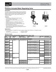
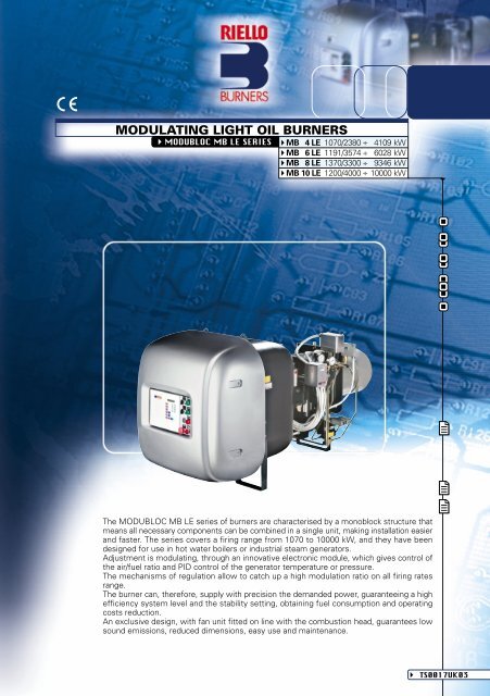
MODULATING LIGHT OIL BURNERSMODUBLOC MB LE SERIESMB 4 LE 1070/2380 ÷ 4109 kWMB 6 LE 1191/3574 ÷ 6028 kWMB 8 LE 1370/3300 ÷ 9346 kWMB 10 LE 1200/4000 ÷ 10000 kWThe MODUBLOC MB LE series of burners are characterised by a monoblock structure thatmeans all necessary components can be combined in a single unit, making installation easierand faster. The series covers a firing range from 1070 to 10000 kW, and they have beendesigned for use in hot water boilers or industrial steam generators.Adjustment is modulating, through an innovative electronic module, which gives control ofthe air/fuel ratio and PID control of the generator temperature or pressure.The mechanisms of regulation allow to catch up a high modulation ratio on all firing ratesrange.The burner can, therefore, supply with precision the demanded power, guaranteeing a highefficiency system level and the stability setting, obtaining fuel consumption and operatingcosts reduction.An exclusive design, with fan unit fitted on line with the combustion head, guarantees lowsound emissions, reduced dimensions, easy use and maintenance.TS0017UK03
TECHNICAL DATAModelMB 4 LEMB 6 LEMB 8 LEMB 10 LEBurner operation modeModulation ratio at max. outputServomotorrun timeHeat outputtypeskWMcal/h1070/2380÷4109920/2047÷3534--Modulating5 ÷ 1MM 100041191/3574÷6028 1370/3300÷93461024/3074÷5184 1178/2838÷8038--1200/4000÷100001032/3440÷8600Approval EmissionsElectrical dataFuel / air dataWorking temperatureNet calorific valueViscosityPumpdeliveryAtomised pressureFuel temperatureFuel pre-heaterFanAir temperatureElectrical supplyAuxiliary electrical supplyControl boxTotal electrical powerAuxiliary electrical powerHeaters electrical powerProtection levelPump motor electrical powerRated pump motor currentPump motor start up currentPump motor protection levelFan motor electrical powerRated fan motor currentFan motor start up currentFan motor protection levelIgnition transformerOperationSound pressureSound powerCO emissionGrade of smoke indicatorCxHy emissionNOx emissionDirectiveConforming toCertificationkg/h°C min./max.kWh/kgkcal/kgmm 2 /s (cSt)typekg/hbarmax. °Ctypemax. °CPh/Hz/VPh/Hz/VtypekWkWkWIPkWAAIPkWAAIPtypeV1 - V2I1 - I2dB (A)Wmg/kWhN° Bacharachmg/kWhmg/kWh90/201÷346100/301÷508116/278÷788101/337÷8430/4011,8102004 ÷ 6 (at 20°C)TA5 CVBHR G1000 (25 bar)1390 (30 bar)2550NOCentrifugal with reverse curve blades603N/50/400~(±10%) - 3/50/230~(±10%)3N/50/400~(±10%)1/50/230~(±10%)LAL 2.25161821,50,80,80,8--401,56,4 - 3,75 x I nom36,77 x I nom5511131538 - 2246,7 - 27327,3 x I nom7,6 x I nom7,6 x I nom25,50,818,4348,1 x I nom55230V - 2x6 kV2,3A - 35 mAIntermittent (at least one stop every 24 h) or Continuos as optional (at least one stop every 72 h)828587--------< 15< 1< 10 (after first 20 s)< 23073/23 - 89/336 - 98/37 EECEN 267DIN 5G 932/99 Min progress (DIN n° ...)Reference conditions:Temperature: 20°CPressure: 1000 mbarAltitude: 100 m a.s.l.Noise measured at a distance of 1 meter.Since the Company is constantly engaged in the production improvement, the aesthetic and dimensional features,the technical data, the equipment and the accessories can be changed.This document contains confidential and proprietary information of RIELLO S.p.A. Unless authorised, this informationshall not be divulged, nor duplicated in whole or in part.
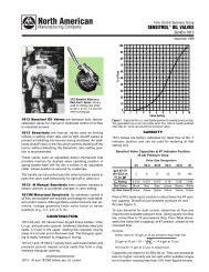
FIRING RATES3002803028MB 8 LEMB 10 LE260262402202422MB 6 LE2001802018MB 4 LE16016140141201210010808606mm H 2O40200hPa (mbar)4200100 200300400 500 600 700 800 900kg/h0 1000 2000 30004000 5000 6000 7000 8000 9000 10000kWUseful working field for choosing the burnerModulation rangeFiring rate in progressTest conditions conforming to EN 267:Temperature: 20°CPressure: 1000 mbarAltitude: 100 m a.s.l.
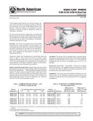
FUEL SUPPLYHYDRAULIC CIRCUITThe hydraulic circuit of the MB series of burners is characterisedby a fuel pump with an independent motor.The burners have two safety valves for the light oil, oneon the delivery circuit and one on the return circuit; theuse of a nozzle with shut-off needle gives even furthersafety.A three way valve is associated to the actuator for openingand closing the nozzle needle, and a servo-driven pressurevariator on the return circuit gives utmost precision tothe amount of fuel burnt.A minimum pressure switch on the oil delivery line meansthat the burners are suitable, from a hydraulic point ofview, for use in steam generators that correspond to TRD604 (Germany), NBN (Belgium) standards.For further information on MB burners series versionswith “continuous operation” contact <strong>Riello</strong> <strong>Burners</strong>Technical Office.PPO minVFVSMMNLUATMRSMROPO maxVRPump with filter and pressure regulatorMin. oil pressure switch on the delivery circuit3 way operating valveSafety valve on the delivery circuitPressure gauge on the delivery circuitNozzle pipeNozzleActuator for opening and closing the nozzle needlePressure gauge on the return circuitServomotorPressure regulator on the return circuitMax. oil pressure switch on the return circuitSafety valve on the return circuitExample of the MB 4 LE burner hydraulic circuitEN 267 > 100 Kg/h (TRD 604, NBN)VSMMVFNLPOminM SMMRATUVRPOmaxROP
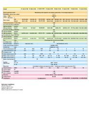
SELECTING THE FUEL SUPPLY LINESThe fuel feed must be completed with the safety devices required by the local norms.The table shows the choice of piping diameter for the various burners, depending on thedifference in height between the burner and the tank and their distance.ModelPiping diameter+H, -H (m)+4,0+3,0+2,0+1,5+1,0+0,50-0,5-1,0-1,5-2,0-3,0-4,0MAXIMUM EQUIVALENT LENGTH FOR THE PIPING L[m]MB 4 LE MB 6 LE MB 8 LE MB 10 LEG 3/4”L max (m)--55504540353025201510-G1”L max (m)--130120110100908070604525-G 3/4”L max (m)--55504540353025201510-G1”L max (m)--130120110100908070604525---------------------------67109 5 VP+H10 cm847 5 3921HØPV12345678910Difference in height pump-foot valveInternal pipe diameterHeight ≤ 10 mHeight ≤ 4 mBurnerBurner pumpFilterManual shut off valveSuction pipeworkBottom valveRemote controlled rapid manualshutoff valve(compulsory in Italy)Type approved shut off solenoid(compulsory in Italy)Return pipeworkCheck valve-H6notewith ring distribution oil systems, the feasible drawings and dimensioning are the responsibilityof specialised engineering studios, who must check compatibility with the requirements andfeatures of each single installation.
VENTILATIONAll the burners in the MBseries are fitted with fanswith reverse curveblades, which giveexcellent performance and are fitted in line with thecombustion head. The air flow and sound-deadeningmaterials that are used in the construction aredesigned to reduce sound emissions to the minimumand guarantee high levels of performance in termsof output and air pressure.A high precision servomotor, through the mainmanagement module installed on each burner of MBseries, controls the air dampers position constantly,Example of the servomotor and dampers for air settingguaranteeing an optimal fuel-air mix.On request, the Modubloc burners can be suppliedwith the “inverter” configuration, which means they are fitted with a device for varying the amountof combustion air through a variable speed action of the fan motor. The addition of the interfaceinverter module means the burner can work at reduced speed, with further benefits in terms of soundemissions, especially during the night when the perception threshold is lower.COMBUSTION HEADthe output of the burner.Simple adjustment of thecombustion head allows to adaptinternal geometry of the head toThe same adjustment servomotor for the air damper also varies,depending on the required output, the setting of the combustionhead, through a simple lever.This system guarantees excellent mix on all firing rates range.Example of a MODUBLOC MB LEburner combustion headFlame dimensions74Flame length (m)65432L maxL minD maxD min3,532,521,51Flame diameter (m)DL10,500 1 2 304 5 6 7 8 9 10Burner output (MW)Example:Burner thermal output = 6000 kW;L flame (m) = 4,7 m (medium value);D flame (m) = 1,2 m (medium value).
ADJUSTMENTBURNER OPERATION MODEEach MB series burner has a mainelectronic microprocessormanagement panel, whichcontrols both the fuel flowservomotor (with a pressureregulator) and air flow servomotor(with air dampers).Hysteresis is prevented by theprecise control of the twoservomotors and the software link.The high precision regulation isdue to the absence of mechanicalclearance normally found in mechanical regulation cams ontraditional modulating burners.Main management moduleInside each MB series burner main electronic microprocessormanagement panel, there is a PID regulator to control the boilertemperature or pressure . Variables can be controlled by specificaccessory probes (see paragraph “Accessories).The burner can run for a long time on intermediate outputsettings (see fig. A)“Modulating” operationChecked Variable°CbarMAXtimeThe main electronic management panel shows all operationalparameters in real time, so as to keep a constant check on theburner:- servomotor angle- required set-point and actual set-point- fuel consumption (measured indirectly)- smoke and environmental temperature (with EGA module)-CO 2 , CO, O 2 , NO e SO 2 value (with EGA module)- burner stage- error checking, self diagnostic fault analysis.OutputFigure AMINtimeThe main electronic management panel operations can be increased by installing accessory modulesas illustrated below. For available module codes see “Accessories”.Special software can be loaded into a portable PC to input and download data through an interfacecable to an infrared device on the front panel of the MB series burner.This is useful both during burner start-up and commissioning phases, and maintenance.
D.T.I. module (Data Transfer interface)This electronic module can transfer multiple signals from differentlocal modules to a BMS supervisor software system (BuildingManagement System).Examples of local modules:- main management module on each MB series burner which sendsand receives signals to indicate or modify the burner working stageD.T.I. module- modules which send and receive signals from the various devicesin the boiler room and system.e.g. - analog modules I/O- digital modules /O- EGA modules(For further information see relative paragraph)Up to ten MB series burners, with or without the EGA module, ten analog modules I/O and ten digitalmodules I/O can be linked up.The DTI module uses MODUBUS interface protocol as a standard protocol to external supervisorysystems (a type of field bus widely used in industrial communication systems).This type of protocol is used when sample signal rates which need checking are low e.g. for temperature,pressure or pump and fan systems.With special electronic interface boards other communication protocols (e.g. PROFIBUS) can be used.DTI module information is transferred directly or by modem to supervisory systems by RS 232 or RS422 (in the case of long distance up to 1 km) connections.The supervisory system can also manage a series of MB burners installed in the same system; eachmain electronic management panel comes with the software needed to manage such a series ofburners.Digital I/O moduleDigital I/O moduleDigital modules I/O transfer in-coming and out-going informationsuch as working stages and alarms, from the boiler room or fromthe system in general where one or more MB series burners areinstalled to a remote supervisor system.Digital modules I/O manage both input and output signals, e.g.:- n. 16 input signals (free contacts – max. current 1 A)- n. 8 output signals (free contacts – max. current 1 A)The out-going signals can control any device in the boiler room, e.g.pumps, fans, etc…The in-coming signals can check any device in the boiler room, e.g.pumps, fans, etc… and receive warning signals such as over heating, excess pressure.Up to ten I/0 digital modules can be linked together. Fig. C shows an example of sequencing I/O digitalmodules linked to a remote supervisor system by a DTI interface.
Analog I/O moduleAnalogic I/O moduleI/O Analog modules transfer in-coming and out-going informationabout burner working stages and other devices in the boiler roomor in the system in general where one or more MB series burnersare installed to a remote supervisor system.I/O Analog modules manage both input and output signals, such as4-20 mA or 0-10 Volt, e.g.:- n. 6 input signals- n. 6 output signalsThese modules can be connected to the remote supervisor systemin two different ways:- “LOW LEVEL” connectioneach I/O analog module transmits information from a single burner to a remote supervisor systemusing 4-20 mA or 0-10 Volt signals, e.g.boiler temperature/pressure, output level, boiler set-point, servomotor angle position, etc.The system becomes operational when each single I/O analog module is programmed by a portablePC and appropriate software.The set point can be modified by a single in-coming 4–20 mA or 0-10 Volt signal from the supervisorsystem.Here is an example of a “LOW LEVEL” connection between I/O analogue modules and remote supervisorsystem. (figure B)BUILDINGMANAGEMENTSYSTEM (BMS)0-10V4-20mA4-20mA0-10V4-20mA4-20mA0-10V4-20mA4-20mA0-10V4-20mA4-20mAAnalogI/O unitAnalogI/O unitAnalogI/O unitAnalogI/O unitMB n°1MB n°2MB n°3MB n°4Figure B - “LOW LEVEL” connection- “HIGH LEVEL” connectioneach I/O analog module transmits in-coming and out-going information about boiler roomtemperature/pressure, pump rpm, set point, to a remote supervisor system using 4-20 mA or 0-10Volt signals, through DTI interface.Up to ten I/0 digital modules can be linked together.
Here is an example of an “HIGH LEVEL” connection between I/O analogue modules and remotesupervisor system. (figure C)DigitalI/O unitAnalogI/O unitDigitalI/O unitAnalogI/O unitMB n°1MB n°2MB n°3MB n°4RS 232modemDTIRS 232 (Modbus protocol)RS 422NetworknodeBUILDINGMANAGEMENTSYSTEM (BMS)RS 422 (Modbus protocol)Figure C - “HIGH LEVEL” connectionE.G.A. module (Exhaust Gas Analyser)E.G.A. moduleEGA modules measure some of the exhaust gas substances. Thesemodules come with an exhaust gas sampler probe and exhaust gastemperature probe (0-400 °C).Four different EGA modules are available depending on the type ofsubstance to be checked. (For further information see “accessories“paragraph).Thanks to EGA module connected to the main electronicmicroprocessor management panel on each MB series burner, theburner can adjust its working parameters on the basis of continuouscombustion gas analysis.The EGA module creates a closed control link which increases efficiencyby up to max 5%.The following functions are also available:- smoke and environmental temperature measurement- viewing of measured parameters on main management display panel- burner lock-out when some parameters exceed permitted levels (settable)- combustion optimisation with automatic air damper setting (adjustment O2 level)- automatic re-adjustment at each firingThe information from EGA modules can be sent to a remote supervisor system in two ways:- through six signals (4-20mA) on a terminal board (see layout fig. B)To activate this operation each single EGA module must be programmed using a PC with appropriatesoftware.- through the DTI interface module (see layout fig. C)Connections between ModulesA data cable type BELDEN 9501 or similar, which can be ordered as an accessory (see accessoriesparagraph), must be used to connect the above modules.noteTo develop the various layouts or for further information about single modules please contact the<strong>Riello</strong> <strong>Burners</strong> Technical Office.
The following diagram summarises how MB series burners and modules can be used for the supervisionof boiler rooms or systems in general.EXHAUSTGASSAMPLING PROBELOAD SENSORPRESSUREAIRSERVOMOTORFUELSERVOMOTORSTEAMLOAD SENSORTEMPERATURELAP TOP FORCOMMISSIONING/SERVICEHOT WATERBOILER ROOM CONTROLS AND ALARMSANALOG I/O UNIT DIGITAL I/O UNITINFRAREDPORTRS 232 MODEM(MODBUS PROTOCOL)MODEMRS 232REMOTEMONITORING& SERVICESUPPORTORRS 232 (MODBUS PROTOCOL)RS 232 (MODBUS PROTOCOL)CUSTOMER BUILDINGMANAGEMENT SYSTEMNETWORKNODELOCALAREANETWORKCUSTOMERBUILDINGMANAGEMENTSYSTEMORRS 422(MODBUS PROTOCOL)RS 422 (MODBUS AND OTHERS PROTOCOLCUSTOMER BUILDINGMANAGEMENT SYSTEMNETWORKNODELOCALAREANETWORKCUSTOMERBUILDINGMANAGEMENTSYSTEMExample of boiler room management systemSTART UP CYCLEMB 4-6-8-10 LE123456max 22,5min053 2,551 - Closing thermostat2 - Fan motor working3 - Air damper4 - Ignition transformer5 - Oil valves open6 - Flame presence0time (s)
CWIRING DIAGRAMSElectrical connectionsmust be made byqualified and skilledpersonnel, according tothe local norms.Example of the terminal boardfor electrical connectionsTHREE PHASE SUPPLY TO THE POWER CIRCUIT AND CONNECTING THE AUXILIARYCONTROLSMB 4-6-8-10 LEXT1X1 1 26 7X3 1 2L1 L2 L3 N PEFX1 PELL1 L2 L3 NPE3N ~ 50Hz 400/230VP ϑTLP ϑTSXT1 - General supply terminal boardX1 - 10 pin plugX3 - Available for oil circuit externalinterlockTS - Safety thermostatTL - Threshold thermostatF - Fuse (refer to table A)L - Lead section (refer to table A)CONNECTION OF THE PROBES FOR THE CONTROLLED PARAMETER AND DATACONNECTION FOR THE VARIOUS MODULES (Accessories)MB 4-6-8-10 LEX25 67 8 9 10X81 2 3 4 5 6 7 8 9 10X2 PEX8 PEde0 - 5VDCcBPBEBTABDX2 - 10 pin plugX8 - 10 pin plug for connectingaccessoriesBT - Temperature probeBP - Pressure probeBE - External modulationA - E.G.A. module connectionsB - Main, D.T.I., I/O modulesconnectionsCD- Boilers sequence- Free contacts for lead boilerchoice of sequenceSIGNALS FOR WORKING STATUS OF THE MAIN COMPONENTSMB 4-6-8-10 LEX71 2 3 4 5 6 7 8 9 10SLX8 X7 X6 X5X7 PEFan onMotor lock outBurner lock outFlame alight230V - 50HzX1 X2 X3 X4X7 - 10 pin output plug,free contactsSL - Layout plug diagramX4, 5, 6 - Plugs forelectricalfactory-setconnectionsThe following table showsthe supply lead sections andthe type of fuse to be used.Table AModelFLAmm 2230V50A aM10MB 4 LE MB 6 LE MB 8 LE MB 10 LE400V32A aM6230V50A aM10400V32A aM6400V40A aM10400V50A aM10
EMISSIONSmg/kWh250200150NO2 EMISSIONS100500MB 4 LE MB 6 LE MB 8 LE MB 10 LEmg/kWh252015CO EMISSIONS1050MB 4 LE MB 6 LE MB 8 LE MB 10 LEThe emission data has been measured in the various models at maximum output, according toEN 267 standard.
SOUND EMISSIONSdB10090MB 4 LE80706050403020100(A)3263 125 250 500 1 K 2 K 4 K 8 K 16 KHz100MB 6 LEdB9080706050403020100(A)3263 125 250 500 1 K 2 K 4 K 8 K 16 KHz100MB 8 -10 LEdB9080706050403020100(A)3263 125 250 500 1 K 2 K 4 K 8 K 16 KHz(A) Value obtained in dB(A)Maximum modulationMinimum modulation
OVERALL DIMENSIONS (mm)BURNERMB 4-6-8-10 LEENFAHDIOSOSModelADEFHINOSMB 4 LEMB 6 LEMB 8 LEMB 10 LE8408401007100791091010791079147014701900190051151153053033633641341349049057557518318320820812051205157015701330133017401740BURNER - BOILER MOUNTING FLANGE45°45°D1D2ØModelMB 4 LEMB 6 LEMB 8 LEMB 10 LED1350350418418D2496496608608ØM20M20M20M20PACKAGINGZXYModel X Y Z kgMB 4 LEMB 6 LEMB 8 LEMB 10 LE212021202690269010051005117011701175117513501350300 39300 41450 42450
INSTALLATION DESCRIPTIONInstallation, start up and maintenance must be carried out byqualified and skilled personnel.All operations must be performed in accordance with the technicalhandbook supplied with the burner.Access to the internal components is very simple, as the back of the burner is hinged which meansit can be completely opened.The burners can be supplied with the opening on the right or left, depending on personal requirements.BURNER SETTINGAll the burners have lifting rings, for easier installationand maintenance.After drilling the boilerplate, using the supplied gasketas template, prepare a suitable lifting system and,after hooking onto the rings, fix burner to the boiler.Install the nozzle, choosing it on the basis of themaximum boiler output and on the basis of thediagrams enclosed with the burner instructions.Adjust the combustion head run, using the mechanismlever.HYDRAULIC / ELECTRICAL CONNECTIONSAND START UPThe burner are supplied for connection to two pipesfuel supply system.Connect the ends of the flexible pipes to the suctionand return pipework using the supplied nipples.Make the electrical connections to the burner followingthe wiring diagrams included in the instructionhandbook.Prime the pump, by turning the motor (check rotationdirection corresponds with the arrow printed on thepump motor cover and that the led signalling correctrotation direction, at left of the plugs group, is on)On start up, check:- Pressure at the pump, the regulator and the valveunit (to max. and min.)- Combustion quality, in terms of unburned substancesand excess air.
BURNER ACCESSORIESDTI module (Data Transfer Interface)This electronic module can transfer multiple signals from different localmodules to a BMS supervisor software system (Building ManagementSystem).BurnerMB 4 - 6 - 8 - 10 LEDTI moduleModule code3010234I/O digital moduleDigital modules I/O transfer in-coming and out-going information such as working stages and alarms,from the boiler room or from the system in general where one or more MB series burners are installedto a remote supervisor system.BurnerMB 4 - 6 - 8 - 10 LEI/O digital moduleModule code3010233I/O analogic moduleI/O Analog modules transfer in-coming and out-going information about burner working stages andother devices in the boiler room or in the system in general where one or more MB series burnersare installed to a remote supervisor system.I/O Analog modules manage both input and output signals, such as 4-20 mA or 0-10 VoltBurnerMB 4 - 6 - 8 - 10 LEI/O analogic moduleModule code3010232
EGA module (Exhaust Gas analyser)EGA modules measure some of the exhaust gas substances. These modules come with an exhaustgas sampler probe and exhaust gas temperature probe (0-400 °C).Four different EGA modules are available depending on the type of substance to be checked, as givenin the following table:BurnerMB 4 - 6 - 8 - 10 LEMB 4 - 6 - 8 - 10 LEMB 4 - 6 - 8 - 10 LEMB 4 - 6 - 8 - 10 LEEGA moduleAnalysed gasCO, CO 2 , O 2CO, CO 2 , O 2 , NOCO, CO 2 , O 2 , SO 2CO, CO 2 , O 2 , NO, SO 2Module code3010235301023630102373010238Belden 9501 type leadsAll the connections for the above modules must be done using a BELDEN 9501 type lead, which isavailable as an accessory in coils of 50 m.BurnerMB 4 - 6 - 8 - 10 LEBelden 9501 leadLead code3010239Accessories for modulating operationMain management module allows a modulating operation with use of probes chosen on the basisof the application.The following table lists the accessories for modulating operation, with the application field.ProbeBurnerMB 4 - 6 - 8 - 10 LEMB 4 - 6 - 8 - 10 LEMB 4 - 6 - 8 - 10 LEMB 4 - 6 - 8 - 10 LEProbe typeTemperaturePressurePressurePressureRange (°C) (bar)0 ÷ 400°C0 ÷ 3 bar0 ÷ 18 bar0 ÷ 30 barProbe code3010187301024630101863010188
NozzlesThe return nozzles with needle cut-off must be ordered separately. The following table shows thefeatures and codes, on the basis of maximum fuel output that is required.Nozzles type B5 45°BurnerMB 4 LEMB 6 LEMB 8 LERated deliverykg/h (*)200225250275300325350375400425450475500300325350375400425450475500Nozzlecode3009800300980130098023009803300980430098053009806300980730098083009809300981030098113009812300980430098053009806300980730098083009809300981030098113009812(*) Nozzle rated delivery is referred to atomised pressureBurnerMB 8 LEMB 10 LERated deliverykg/h (*)525550575600650700400425450475500525550575600650700750800850900Nozzlecode300981330098143009815300981630098173009818300980830098093009810300981130098123009813300981430098153009816300981730098183009819300982030098213009822Burner supportFor easier maintenance, a mobile burner support has been designed, which means the burner canbe dismantled without the need for forklift trucks.Burner supportBurnerMB 4 - 6 LEMB 8 - 10 LESupport codeIn progressIn progress
SPECIFICATIONA specific index guides your choice of burner fromthe various models available in the MODUBLOC MBseries. Below is a clear and detailed specificationdescription of the product.DESIGNATION OF SERIESSeries : MBSizeFuel : S Natural GasL Light oilLS Light oil/MethaneSetting : E Electronic camV Electronic cam and variable speed (with Inverter)P Proportioning air/gas valveEmission : ... Class 1 EN267 - EN676MZ Class 2 EN267 - EN676BLU Class 3 EN267 - EN676MXClass 2 EN267Class 3 EN676Head : TC Standard headTL Extended headFuel supply : FR from the rightFL from the leftFlame control system :FS1 Standard (1 stop every 24 h)FS2 Continuous working (1 stop every 72 h)Electrical supply to the system :3/400/50 3N/400V/50Hz3/230/50 3/230V/50HzAuxiliary voltage :230/50-60 230V/50-60Hz110/50-60 110V/50-60HzMB4 L E TC FR FS1 3/400/50 230/50-60BASIC DESIGNATIONEXTENDED DESIGNATION
AVAILABLE BURNER MODELSMB4LE TC FR FS1 3/400/50 230/50-60MB4LE TC FR FS1 3/230/50 230/50-60MB4LE TC FL FS1 3/400/50 230/50-60MB4LE TC FL FS1 3/230/50 230/50-60MB6LE TC FR FS1 3/400/50 230/50-60MB6LE TC FR FS1 3/230/50 230/50-60MB6LE TC FL FS1 3/400/50 230/50-60MB6LE TC FL FS1 3/230/50 230/50-60MB8LE TC FR FS1 3/400/50 230/50-60MB8LE TC FR FS2 3/400/50 230/50-60MB8LE TC FL FS1 3/400/50 230/50-60MB8LE TC FL FS2 3/400/50 230/50-60MB10LE TC FR FS1 3/400/50 230/50-60MB10LE TC FR FS2 3/400/50 230/50-60MB10LE TC FL FS1 3/400/50 230/50-60MB10LE TC FL FS2 3/400/50 230/50-60Other versions are available on request.PRODUCT SPECIFICATIONBurner:Monoblock forced draught oil burner with modulating operation, fully automatic, made up of:- fan with reverse curve blades high performance with low sound emissions- air suction circuit lined with sound-proofing material- air damper for air setting controlled by a high precision servomotor- air pressure switch- fan starting motor at 2900 rpm, three-phase 230/400 - 400/690 V with neutral, 50Hz- pump starting motor at 2900 rpm, three phase 230/400 V 50Hz- mobile combustion head, that can be set on the basis of required output, fitted with:- stainless steel end cone, resistant to corrosion and high temperatures- ignition electrodes- flame stability disk- gears pump for high pressure fuel supply, fitted with:- filter- pressure regulator- connections for installing a pressure gauge and vacuum meter- internal by pass for single pipe installation- valve unit containing:- oil safety valve on the delivery circuit- oil safety valve on the return circuit- three way valve for the actuator- actuator for opening and closing the nozzle needle- automatic setting for light oil delivery, controlled by a high precision servomotor- safety oil pressure switch for stop the burner in the case of problems in the return circuit- pressure gauge for delivery pressure- pressure gauge for return pressure- minimum oil pressure switch on the delivery circuit (TRD 604, NBN standards)- module for air/fuel setting and output modulation with incorporated PID control of temperatureor pressure of the heat generator
- flame control panel for controlling the system safety- photocell for flame detection- star/triangle starter for the fan motor- main electrical supply terminal board- pump motor starter- burner on/off switch- auxiliary voltage led signal- manual or automatic output increase/decrease switch- burner working led signal- contacts motor and thermal relay with release button- motor internal thermal protection- motor failure led signal- burner failure led signal and lighted release button- led signal for correct rotation direction of fan and pump motor- emergency button- coded connection plugs-sockets- burner opening hinge- lifting rings- IP 40 electric protection level.Conforming to:- 89/336/CEE directive (electromagnetic compatibility)- 73/23/CEE directive (low voltage)- 98/37/EEC directive (machinery)- EN 267 (liquid fuel burners).Standard equipment:- 2 flexible pipes for connection to the oil supply network- 2 gaskets for the flexible pipes- 2 nipples for connection to the pump- 4 screws for fixing the burner flange to the boiler- 1 thermal screen- instruction handbook for installation, use and maintenance- spare parts catalogue.Available accessories to be ordered separately:- DTI module (Data Transfer Interface)- I/O digital module- I/O analogic module- EGA module (Exhaust Gas Analyser) in the following versions:- EGA - C0, CO 2 , 0 2- EGA - CO, CO 2 , O 2 , NO- EGA - CO, CO 2 , O 2 , SO 2- EGA - CO, CO 2 , O 2 , NO, SO 2- BELDEN 9501 type lead- Pressure probe 0 ÷ 3 bar- Pressure probe 0 ÷ 18 bar- Pressure probe 0 ÷ 30 bar- Temperature probe 0 ÷ 400°C- Return nozzles with needle cut-off- Burner support.
LineagraficaISO 9001 Cert. n. 0061RIELLO S.p.A. - Via degli Alpini, 1 - 37045 LEGNAGO (VR) ItalyTel. ++39.0442630111 - Fax ++39.044221980Internet: http://www.rielloburners.com - E-mail: rburners@rielloburners.comSince the Company is constantly engaged in the production improvement, the aesthetic anddimensional features, the technical data, the equipment and the accessories can be changed.This document contains confidential and proprietary information of RIELLO S.p.A.Unless authorised, this information shall not be divulged, nor duplicated in whole or in part.