Axial Piston Variable Pump AA4VG - Bosch Rexroth
Axial Piston Variable Pump AA4VG - Bosch Rexroth
Axial Piston Variable Pump AA4VG - Bosch Rexroth
- No tags were found...

You also want an ePaper? Increase the reach of your titles
YUMPU automatically turns print PDFs into web optimized ePapers that Google loves.
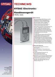
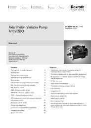
Electric Drivesand ControlsHydraulicsLinear Motion andAssembly TechnologiesPneumaticsService<strong>Axial</strong> <strong>Piston</strong> <strong>Variable</strong> <strong>Pump</strong><strong>AA4VG</strong>RA 92003-A/06.09 1/64Replaces: 03.09Data sheetSeries 32Size 28 ... 250Nominal pressure 5800 psi (400 bar)Peak pressure 6500 psi (450 bar)Closed circuitContentsOrdering Code / Standard Program 2Technical Data 5High-Pressure Relief Valves 9Pressure Cut-Off, D 10NV - Version Without Control Unit 11DG - Hydraulic Control, Direct Operated 11EZ - Electric Two-Point Control, With Switching Solenoid 11HD - Hydraulic Control, Pilot-Pressure Related 12HW - Hydraulic Control, Mechanical Servo 13EP - Electric Control, With Proportional Solenoid 14DA - Hydraulic Control, Speed Related 16Unit Dimensions, Size 28 18Unit Dimensions, Size 40 22Unit Dimensions, Size 56 26Unit Dimensions, Size 71 30Unit Dimensions, Size 90 34Unit Dimensions, Size 125 38Unit Dimensions, Size 180 42Unit Dimensions, Size 250 46Through Drive Dimensions 50Overview of Attachments on <strong>AA4VG</strong> 53Combination <strong>Pump</strong>s <strong>AA4VG</strong> + <strong>AA4VG</strong> 53Mechanical Stroke Limiter, M 54Ports X 3 and X 4 for Positioning Pressure, T 54Filtration Types 55Swivel Angle Indicator 59Connector for Solenoids (Only for EP, EZ, DA) 60Rotary Inch Valve 61Installation Situation for Coupling Assembly 62Installation Notes 63General Notes 64Features– <strong>Variable</strong> axial piston pump of swashplate design for hydrostaticclosed circuit transmissions– Flow is proportional to drive speed and displacement and isinfinitely variable– Output flow increases with the swivel angle of the swashplatefrom 0 to its maximum value– Flow direction changes smoothly when the swashplate ismoved through the neutral position– A wide range of highly adaptable control devices is availablefor different control and regulating functions– The pump is equipped with two pressure relief valves on thehigh pressure ports to protect the hydrostatic transmission(pump and motor) from overload– The high-pressure relief valves also function as boost valves– The integrated boost pump acts as a feed and control oilpump– The maximum boost pressure is limited by a built-in boostpressure relief valve– The integral pressure cut-off is standard
2/64 <strong>Bosch</strong> <strong>Rexroth</strong> Corp. <strong>AA4VG</strong> RA 92003-A/06.09Ordering Code / Standard ProgramAA4V G D / 32 – N01 02 03 04 05 06 07 08 09 10 11 12 13 14 15 16 17 18 19 20 21 22<strong>Axial</strong> piston unit01 <strong>Variable</strong> swashplate design, nominal pressure 5800 psi (400 bar), peak pressure 6500 psi (450 bar) AA4VOperation mode02 <strong>Pump</strong> in closed circuit GSize03 ≈ Displacement V g max in 3 /rev. 1.71 2.44 3.42 4.33 5.49 7.63 10.98 15.25cm 3 /rev. 28 40 56 71 90 125 180 25004Control device 28 40 56 71 90 125 180 250Without control unit ● ● ● ● ● ● ● ● NVHydraulic control pilot-pressure related with supply filtration ● ● ● ● ● ● ● ● HD3Electric controlmechanical servo ● ● ● ● ● ● ● ● HWdirect operated ● ● ● ● ● ● ● ● DGspeed relatedU = 12 V DC ● ● ● ● ● ● ● ● DA1(Description DAcontrol valve in Pos. 09) U = 24 V DC ● ● ● ● ● ● ● ● DA2with proportional solenoid U = 12 V DC ● ● ● ● ● ● ● ● EP3with supply filtration U = 24 V DC ● ● ● ● ● ● ● ● EP4with switching solenoid U = 12 V DC ● ● ● ● ● ● ● ● EZ1U = 24 V DC ● ● ● ● ● ● ● ● EZ2Pressure cut-off 28 40 56 71 90 125 180 25005 With pressure cut-off (standard) ● ● ● ● ● ● ● ● DNeutral position switch (only for HW) 28 40 56 71 90 125 180 250Without neutral position switch (without code) ● ● ● ● ● ● ● ●06With neutral position switch (with DEUTSCH connector) ● ● ● ● ● ● ● ● LMechanical stroke limiter 28 40 56 71 90 125 180 250Without mechanical stroke limiter (without code) ● ● ● ● ● ● ● ●07With mechanical stroke limiter, external variable ● ● ● ● ● ● ● ● MPorts X 3 , X 4 for positioning pressure 28 40 56 71 90 125 180 25008 Without ports X 3, X 4 (without code) ● ● ● ● ● ● ● ●With ports X 3 , X 4 ● ● ● ● ● ● ● ● TDA control valve NV HD1 HW DG DA EP EZWithout DA control valve ● ● ● ● – ● ● 1With DA control valve, fixed setting – ● ● ● ● ● – 2With DA control valve, mech. clockwise – ● ● ● ● ● – 3Radjustable with position lever counter-clockwise – ● ● ● ● ● – 3L09With DA control valve, fixed setting and hydraulic inch valve mounted,control with brake fluid according to ISO 4925, no mineral oil– – – – ● – – 4With DA control valve, fixed setting and ports for pilot control device – ● ● ● ● ● – 7With DA control valve, fixed setting and hydraulic inch valve mounted,control with brake fluid based on mineral oil– – – – ● – – 8
RA 92003-A/06.09 <strong>AA4VG</strong> <strong>Bosch</strong> <strong>Rexroth</strong> Corp. 3/64Ordering Code / Standard ProgramAA4V G D / 32 – N01 02 03 04 05 06 07 08 09 10 11 12 13 14 15 16 17 18 19 20 21 22Series10 Series 3, Index 2 32Direction of rotationViewed from shaft end clockwise R11counter-clockwise LSeals12 NBR (nitrile-caoutchouc), shaft seal ring in FKM (fluor-caoutchouc) NShaft end (permissible input torque see page 8) 28 40 56 71 90 125 180 250Splined shaftfor single pump ● ● ● ● ● ● ● ● S13ANSI B92.1a–1976for combination pump - 1st pump – 1 ) – 1 ) ● ● – 1 ) ● ● ● Tonly for combination pump - 2nd pump – ● – – ● – – – UMounting flange 28 40 56 71 90 125 180 250SAE J744 – 2-bolt ● ● ● – – – – – C14 SAE J744 – 4-bolt – – – – – – ● ● DSAE J744 – 2+4-bolt – – – ● ● ● – – FService line ports (UN fixing thread) 28 40...180 250SAE flange portssuction port S bottom – ● – 5215A/B top and bottomsuction port S at top – ❍ – 53SAE flange portsright suction port S bottom ● – ● 60A/B same sideleft suction port S at top ❍ – ❍ 63Boost pump 28 40 56 71 90 125 180 250Without integrated boost pump without through drive ● ● ● ● ● ● ● ● N0016with through drive ● ● ● ● ● ● ● ● K..With integrated boost pump without through drive ● ● ● ● ● ● ● ● F00with through drive ● ● ● ● ● ● ● ● F..Through drive (mounting options, see page 53)Flange SAE J744 2 ) Hub for splined shaft 28 40 56 71 90 125 180 25082-2 (A) 5/8 in 9T 16/32DP 3 ) ● ● ● ● ● ● ● ● .01101-2 (B) 7/8 in 13T 16/32DP 3 ) ● ● ● ● ● ● ● ● .021 in 15T 16/32DP 3 ) ● ● ● ● ● ● ● ● .0417 127-2 (C) 1 in 15T 16/32DP 3 ) – ● – – – – – – .091 1/4 in 14T 12/24DP 3 ) – – ● ● ● ● ● ● .07152-2/4 (D) 1 1/4 in 14T 12/24DP 3 ) – – – – ● – – – .901 3/4 in 13T 8/16DP 3 ) – – – – – ● ● ● .69165-4 (E) 1 3/4 in 13T 8/16DP 3 ) – – – – – – ● ● .72
4/64 <strong>Bosch</strong> <strong>Rexroth</strong> Corp. <strong>AA4VG</strong> RA 92003-A/06.09Ordering Code / Standard ProgramAA4V G D / 32 – N01 02 03 04 05 06 07 08 09 10 11 12 13 14 15 16 17 18 19 20 21 22Valves setting range Δp 28 40 56 71 90 125 180 250With high-pressure relief valve, pilot operated 1450...6100 psi 4 ) with bypass – – – ● ● ● ● ● 1With high-pressure relief valve,3900...6100 psi without bypass ● ● ● – – – – – 318direct operated (fixed setting)(270...420 bar) with bypass ● ● ● – – – – – 51450...3600 psi without bypass ● ● ● – – – – – 4(100...250 bar) with bypass ● ● ● – – – – – 6Filtration 28 40 56 71 90 125 180 250Filtration in the suction line of boost pump (filter not included in supply) ● ● ● ● ● ● ● ● SFiltration in pressure line of boost pumpports for external boost circuit filtration, (F e and F a )● ● ● ● ● ● ● ● Dand cold start valve – ● ● ● ● ● ● – K19 Filter mounted with cold start valve but without contamination indicator – ● ● ● ● ● ● – FFilter mounted withcold start valve andwindow – ● ● ● ● ● ● – Pcontamination indicatorthrough:electr. signal - DEUTSCH connector – ● ● ● ● ● ● – BExternal supply (version without integral boost pump - N00, K..) ● ● ● ● ● ● ● ● ESwivel angle indicator 28 40 56 71 90 125 180 250Without swivel angle indicator (without code) ● ● ● ● ● ● ● ●20Electrical swivel angle sensor ● ● ● ● ● ● ● ● RConnector for solenoids (only for EP, EZ, DA) 28 40 56 71 90 125 180 250DEUTSCH connector without suppressor diode ● ● ● ● ● ● ● ● P21molded, 2-pinwith suppressor diode (only for EZ and DA) ❍ ❍ ❍ ❍ ❍ ❍ ❍ ❍ QStandard / special version 5 )Standard versionwithout codecombined with attachment part or attachment pump -K22Special version -Scombined with attachment part or attachment pump-SK1 ) Standard for combination pump – 1st pump: shaft S2 ) 2 = 2-bolt; 4 = 4-bolt3 ) Hub for splined shaft acc. to ANSI B92.1a-1976 (splined shaft assigned acc. to SAE J744, see page 50-52 )4 ) (100...420 bar)5 ) Adjustment data are included in the material number= available ❍ = on request – = not available
RA 92003-A/06.09 <strong>AA4VG</strong> <strong>Bosch</strong> <strong>Rexroth</strong> Corp. 5/64Technical DataHydraulic fluidBefore starting project planning, please refer to our data sheetsRE 90220 (mineral oil), RE 90221 (environmentally acceptablehydraulic fluids) and RE 90223 (HF hydraulic fluids) for detailedinformation regarding the choice of hydraulic fluid and applicationconditions.The variable pump <strong>AA4VG</strong> is unsuitable for operation withHFA, HFB and HFC. If HFD or environmentally acceptable hydraulicfluids are being used, the limitations regarding technicaldata and seals mentioned in RE 90221 and RE 90223 mustbe observed.When ordering, please indicate the used hydraulic fluid.Operating viscosity rangeFor optimum efficiency and service life, select an operating viscosity(at operating temperature) within the optimum range ofν opt = opt. operating viscosity 80...170 SUS (16...36 mm 2 /s)depending on the circuit temperature (closed circuit).Limits of viscosity rangeThe limiting values for viscosity are as follows:ν min = 42 SUS (5 mm 2 /s)short term (t < 3 min)at max. perm. temperature of t max = +240 °F (+115 °C)ν max = 7400 SUS (1600 mm 2 /s)short term (t < 3 min)at cold start (p ≤ 435 psi / 30 bar, n ≤ 1000 rpm,t min = -40 °F / -40 °C).Only for starting up without load. Optimum operatingviscosity must be reached within approx. 15 minutes.Note that the maximum hydraulic fluid temperature of 240°F (115 °C) must not be exceeded locally either (e.g. in thebearing area). The temperature in the bearing area is - dependingon pressure and speed - up to 9 °F (5 K) higher than theaverage case drain temperature.Special measures are necessary in the temperature range from-40 °F to -13 °F (-40 °C to -25 °C) (cold start phase), pleasecontact us.For detailed information about use at low temperatures, seeRE 90300-03-B.Selection diagramViscosity ν SUS (mm2/s)700050003000200010005003002001501008070605040(1600)(1000)(600)(400)(200)(100)(60)(40)(20)(10)(5)VG 22VG 32VG 46VG 100VG 687400 (1600)4600 (1000)170(36)ν opt.80(16)60 (10)42 (5)-40 -200 40 80 120 160 200 24020 60 100 140 180 220(-40) (-20) (0) (20) (40) (60) (80) (100) (115)(-30) (-10) (10) (30) (50) (70) (90) (110)Temperature t in °F (°C)Details regarding the choice of hydraulic fluidThe correct choice of hydraulic fluid requires knowledge of theoperating temperature in relation to the ambient temperature: ina closed circuit the circuit temperature.The hydraulic fluid should be chosen so that the operating viscosityin the operating temperature range is within the optimumrange (ν opt ) - the shaded area of the selection diagram. Werecommended that the higher viscosity class be selected ineach case.Example: At an ambient temperature of X °F (X °C) an operatingtemperature of 140 °F (60 °C) is set in the circuit. Inthe optimum operating viscosity range (ν opt ; shaded area) thiscorresponds to the viscosity classes VG 46 or VG 68; to beselected: VG 68.Please note: The case drain temperature, which is affected bypressure and speed, is always higher than the circuit temperature.At no point in the system may the temperature be higherthan 240 °F (115 °C).If the above conditions cannot be maintained due to extremeoperating parameters, please consult us.
6/64 <strong>Bosch</strong> <strong>Rexroth</strong> Corp. <strong>AA4VG</strong> RA 92003-A/06.09Technical DataFiltrationThe finer the filtration, the higher the cleanliness level of thehydraulic fluid and the longer the service life of the axial pistonunit.To ensure functional reliability of the axial piston unit the hydraulicfluid must have a cleanliness level of at least20/18/15 according to ISO 4406.Depending on the system and the application, for the <strong>AA4VG</strong>,we recommendFilter elements β 20 ≥ 100With a rising differential pressure at the filter elements, theβ-value must not deteriorate.At very high hydraulic fluid temperatures (195 °F to max. 240 °F /90 °C to max. 115 °C) at least cleanliness level19/17/14 according to ISO 4406 is required.If the above classes cannot be observed, please contact us.For notes on filtration types, see pages 55-58Operating pressure rangeInput<strong>Variable</strong> pump (with external supply, E):For control EP, EZ, HW and HDboost pressure (at n = 2000 rpm) p Sp ______ 290 psi (20 bar)For control DA, DGboost pressure (at n = 2000 rpm) p Sp ______ 365 psi (25 bar)Boost pump:suction pressure p σ μιν (ν ≤ 30 mm 2 /s) __ ≥ 12 psi a (0.8 bar abs.)at cold starts, short term (t < 3 min) ____ ≥ 7.5 psi a (0.5 bar abs.)Output<strong>Variable</strong> pump:pressure at port A or B(pressure data according to DIN 24312)Nominal pressure p N ___________________5800 psi (400 bar)Peak pressure p max ____________________6500 psi (450 bar)Shaft seal ringPermissible pressure loadingThe service life of the shaft seal ring is affected by the speedof the pump and the case drain pressure. It is recommendedthat the average, continuous case drain pressure at operatingtemperature 45 psi (3 bar) absolute not be exceeded(max. permissible case drain pressure 90 psi (6 bar) absoluteat reduced speed, see diagram). Short term (t < 0.1 s) pressurespikes of up to 145 psi (10 bar) absolute are permitted. Theservice life of the shaft seal ring decreases with an increase inthe frequency of pressure spikes.The case pressure must be equal to or greater than the externalpressure on the shaft seal ring.Perm. pressure pabs. max. psi (bar)SizesSize 250 Size 125 40,56Size 180 Sizes 71,90 Size 2890 (6)75 (5)60 (4)45 (3)30 (2)15 (1)1000Size90Size71Size562000 3000 4000 5000Speed n in rpmSize 28Size 40Temperature rangeThe FKM shaft seal ring is permissible for case temperatures of-13 °F to +240 °F (-25 °C to +115 °C).Note:For application cases below -13 °F (-25 °C), an NBR shaft sealring is necessary (permissible temperature range: -40 °F to+195 °F / -40 °C to +90 °C). Please state NBR shaft seal ringin plain text when ordering. Please contact us.Boost pump:peak pressure p Sp max ____________________ 580 psi (40 bar)Nominal pressure: Max. design pressure at which fatiguestrength is ensured.Peak pressure:Max. operating pressure which is permissiblefor short term (t
RA 92003-A/06.09 <strong>AA4VG</strong> <strong>Bosch</strong> <strong>Rexroth</strong> Corp. 7/64Technical DataTable of values (theoretical values, without effi ciencies and tolerances; values rounded)Size 28 40 56 71 90 125 180 250Displacement V g max in 3 1.71 2.44 3.42 4.33 5.49 7.63 10.98 15.25variable pump cm 3 28 40 56 71 90 125 180 250boost pump (at p = 290 psi / 20 bar) V g Sp in 3 0.37 0.52 0.71 1.20 1.20 1.73 2.43 3.20cm 3 6.1 8.6 11.6 19.6 19.6 28.3 39.8 52.5Speedmaximum at V g max n max continuous rpm 4250 4000 3600 3300 3050 2850 2500 2400limited maximum 1 ) n max limited rpm 4500 4200 3900 3600 3300 3250 2900 2600intermittent maximum 2 ) n max interm. rpm 5000 5000 4500 4100 3800 3450 3000 2700minimum n min rpm 500 500 500 500 500 500 500 500Flow q v max gpm 31.5 42.3 53.4 61.8 72.5 94.1 118.8 158.4at n max continuous and V g max l/min 119 160 202 234 275 356 450 600Power 3 ) Δp = 5800 psi P max hp 106 144 180 209 245 318 402 536at n max continuous and V g max Δp = 400 bar kW 79 107 134 156 183 237 300 400Torque 3 ) Δp = 5800 psi T max lb-ft 131 187 263 333 422 587 844 1173at V g max Δp = 400 bar Nm 178 255 356 451 572 795 1144 1590Δp = 1450 psi T lb-ft 22.7 32.4 45.4 57.4 72.8 101.2 145.6 202.2Δp = 100 bar Nm 44.5 63.5 89 112.8 143 198.8 286 398Rotary stiffness shaft end S c lb-ft/rad 23159 50892 59595 72871 116609 161010 180334 261466Nm/rad 31400 69000 80800 98800 158100 218300 244500 354500shaft end T c lb-ft/rad – – 70068 89171 – 185939 234840 394079Nm/rad – – 95000 120900 – 252100 318400 534300shaft end U c lb-ft/rad – 37468 – – 79362 – – –Nm/rad – 50800 – – 107600 – – –Moment of inertia for rotary group J GR lbs-ft 2 0.0522 0.0902 0.1566 0.2302 0.3536 0.5505 1.0536 2.3327kgm 2 0.0022 0.0038 0.0066 0.0097 0.0149 0.0232 0.0444 0.0983Angular acceleration max. 4 ) α rad/s 2 38000 30000 24000 21000 18000 14000 11000 6700Filling capacity V gal 0.24 0.29 0.40 0.34 0.40 0.55 0.82 1.66L 0.9 1.1 1.5 1.3 1.5 2.1 3.1 6.3Weight approx. (without through drive) m lbs 64 68 84 110 145 176 223 344kg 29 31 38 50 60 80 101 1561) Restricted maximum speed: – at half corner power (e.g. at V g max and p N /2)2 ) Intermittent maximum speed: – at high idle speed– at overspeed: Δp = 70...150 bar and V g max– at reversing peaks: Δp < 300 bar and t < 0.1 s.3 ) Without boost pump4 ) – The area of validity is situated between the minimum required and maximum permissible speed.It applies for external stimuli (e.g. engine 2-8 times rotary frequency, cardan shaft twice the rotary frequency).– The limit value applies for a single pump only.– The load capacity of the connection parts has to be considered.Caution: Exceeding the permissible limit values may result in a loss of function, a reduction in service life or in thedestruction of the axial piston unit.A calculation can be performed to determine the permissible values.Determining the size(((Flow q v = V g • n • η v V g • n • η vgpm231 1000l/minV g • ΔpV g • ΔpTorque T =lb-ftNm24 • π • η mh 20 • π • η mhPower P = 2 π • T • n q v • Δpq v • Δp=HP= 2 π • T • n kW33000 1714 • η t 600 • η t 60000)))V gΔpnη vη mhη t= displacement volume per revolutionin in 3 (cm 3 )= differential pressure in psi (bar)= speed in rpm= volumetric efficiency= mechanical-hydraulic efficiency= total efficiency
8/64 <strong>Bosch</strong> <strong>Rexroth</strong> Corp. <strong>AA4VG</strong> RA 92003-A/06.09Technical DataPermissible axial and radial loading on drive shaftF q max lbf–F lbf 350 476 654 953 973 1291 1585 933Size 28 40 56 71 90 125 180 250Radial force, max.562 809 1124 1416 1798 2473 3597 4946F q F q max lbf 450 650 910 1113 1424 1932 2782 3779at distance (from shaft collar )N 2500 3600 5000 6300 8000 11000 16000 22000a in 0.69 0.69 0.69 0.79 0.79 0.89 0.98 1.14mm 17.5 17.5 17.5 20 20 22.5 25 29N 2000 2891 4046 4950 6334 8594 12375 16809b in 1.18 1.18 1.18 1.38 1.38 1.57 1.77 1.97a,b,cmm 30 30 30 35 35 40 45 50F q max lbf 382 543 764 917 1178 1585 2282 3057N 1700 2416 3398 4077 5242 7051 10150 13600c in 1.67 1.67 1.67 1.97 1.97 2.26 2.36 2.80mm 42.5 42.5 42.5 50 50 57.5 60 71<strong>Axial</strong> force, max.ax max-N 1557 2120 2910 4242 4330 5743 7053 4150F ax+ +F ax max lbf 94 198 335 620 600 867 1112 933N 417 880 1490 2758 2670 3857 4947 4150Note: special requirements apply in the case of belt drives. Please contact us.Permissible input and through-drive torquesSize 28 40 56 71 90 125 180 250Torque (at V g max and Δp = 5800 psi) 1 )(at V g max and Δp = 400 bar) 1 )T max lb-ft 131 187 263 333 422 587 844 1173Nm 178 254 356 451 572 795 1144 1590Input torque, max. 2 )at shaft end S T E perm. lb-ft 232 444 444 444 1210 1210 1210 1210Nm 314 602 602 602 1640 1640 1640 1640ANSI B92.1a-1976 (SAE J744) 1 in 1 1/4 in 1 1/4 in 1 1/4 in 1 3/4 in 1 3/4 in 1 3/4 in 1 3/4 inat shaft end T T E perm. lb-ft – – 715 715 – 1969 3002 3002Nm – – 970 970 – 2670 4070 4070ANSI B92.1a-1976 (SAE J744) 1 3/8 in 1 3/8 in 2 in 2 1/4 in 2 1/4 inat shaft end U 3 ) T E perm. lb-ft – 232 – – 444 – – –Nm – 314 – – 602 – – –ANSI B92.1a-1976 (SAE J744) 1 in 1 1/4 inThrough-drive torque, max. 4 ) T D perm. lb-ft 170 232 384 487 606 819 1298 1645Nm 231 314 521 660 822 1110 1760 22301 ) Efficiency not considered) For drive shafts with no radial force3 ) Shaft “U“ is only permitted as a shaft end on the 2nd pump in a combination pump of the same size.4 ) Note max. input torque for shaft S!Torque distributionT 1 T 2T E1. <strong>Pump</strong>e1st pump2. <strong>Pump</strong>e2nd pumpT D
RA 92003-A/06.09 <strong>AA4VG</strong> <strong>Bosch</strong> <strong>Rexroth</strong> Corp. 9/64High-Pressure Relief ValvesSetting rangesSetting diagramHigh-pressure relief valve,direct operated (size 28...56)Setting range for valve 3, 5Δp 3900 - 6100 psi(Δp 270 - 420 bar)(refer to ordering code)Setting range for valve 4, 6Δp 1450 - 3600 psi(Δp 100 - 250 bar)(refer to ordering code)High-pressure relief valve,pilot operated (size 71...250)Setting range for valve 1Δp 1450 - 6100 psi(Δp 100 - 420 bar)(refer to ordering code)Differential pressuresetting Δp HD6100 psi (420 bar)5800 psi (400 bar) 1 )5200 psi (360 bar)4950 psi (340 bar)4650 psi (320 bar)4350 psi (300 bar)3900 psi (270 bar)3600 psi (250 bar)3350 psi (230 bar) 1 )2900 psi (200 bar)2200 psi (150 bar)1450 psi (100 bar)Differential pressuresetting Δp HD6100 psi (420 bar)5800 psi (400 bar) 1 )5200 psi (360 bar)4950 psi (340 bar)4650 psi (320 bar)4350 psi (300 bar)3900 psi (270 bar)3600 psi (250 bar)3350 psi (230 bar)2900 psi (200 bar)2200 psi (150 bar)1450 psi (100 bar)1 ) Standard differential pressure setting. The valves will be setto this value if the differential pressure is not specified onordering.Operating pressure pA, Bat port A, B≥435 psi(30 bar)SafetyΔp DrivedesignpSpBoostpressureSetting valuepressure cut-offq V1(n = 1000 rpm)Note: valve is set atn = 1000 rpm and V g max (q v 1 )Example: boost pressure 435 psi (30 bar);operating pressure 5800 psi (400 bar)q v maxp maxp Sp(n = nmax)Differential pressure ΔpHDHD valve settingOperating pres. p A,B - boost pres. p Sp + safety = differential pres. Δp HD5800 psi - 435 psi + 435 psi = 5800 psi(400 bar - 30 bar + 30 bar = 400 bar)Bypass functionThe bypass function can only be used for short periods withreduced displacement, e.g. to tow a vehicle out of an immediatedanger zone.Note:The bypass function and the pilot operated high-pressure valves(size 71...250) are not shown in these circuit diagrams.Please state in plain text when ordering:(only the Δp HD values shown in the table are possible)High-pressure relief valve ADifferential pressure setting :Δp HD = ... psi (bar)opening pressure of the HD valve (at q V 1 ): p max = ... psi (bar)(p max = Δp HD + p Sp )High-pressure relief valve BDifferential pressure setting :Δp HD = ... psi (bar)opening pressure of the HD valve (at q V 1 ): p max = ... psi (bar)(p max = Δp HD + p Sp )
10/64 <strong>Bosch</strong> <strong>Rexroth</strong> Corp. <strong>AA4VG</strong> RA 92003-A/06.09Pressure Cut-Off, DThe pressure cut-off corresponds to a pressure regulationwhich, after reaching the set pressure, adjusts the displacementof the pump to V g min .This valve prevents the operation of the high-pressure reliefvalves when accelerating or decelerating.Both the pressure peaks occurring when the swashplate isswiveled rapidly and also the maximum pressure in the systemare safeguarded by the high-pressure relief valves.The setting range of the pressure cut-off may be anywherewithin the entire operating pressure range. However, it must beset 435 psi (30 bar) lower than the setting of the high-pressurerelief valves (see setting diagram, page 9).Please state the setting value of the pressure cut-off in plaintext when ordering.Circuit diagram with pressure cut-off.Example: Electric two-point control, EZ1D/EZ2D
RA 92003-A/06.09 <strong>AA4VG</strong> <strong>Bosch</strong> <strong>Rexroth</strong> Corp. 11/64NV - Version Without Control UnitThe mounting surface for the control unit is machined and issealed with the standard seal for control units and a coverplate. This version is ready for retrofitting to control units (HD,HW, EP, EZ). When used directly for “DA” control and in combinationswith “DA” control, the appropriate adjustments mustbe made to the spring assembly of the adjusting cylinder andcontrol plate.Standard version 1 )DG - Hydraulic Control, Direct Operated1 ) Size 28 and 250 without port F a1 and F SWith the direct operated hydraulic control (DG), pump displacementis controlled by a hydraulic pilot pressure applieddirectly to the stroking piston through either the X 1 or X 2 port.Flow direction is determined by which pilot port is pressurized(please refer to the data table at the top of page 12; controlpressure column- X 1 ; X 2 ).<strong>Pump</strong> displacement is infinitely variable and proportional to theapplied pilot pressure, but is also influenced by system pressureand pump drive speed.The P s port must be used as the pilot pressure source for theselected control device, to enable the function of the built-inpressure cut-off valve. Please refer to page 10 for a descriptionof the pressure cut-off function.Application of the DG Control requires a review of the engineand vehicle parameters to ensure that the pump is set upcorrectly. All DG applications must be reviewed by a <strong>Rexroth</strong>Application Engineer.Standard version 1 )Version with DA control valve 1 )1 ) Size 28 and 250 without port F a1 and F SEZ - Electric Two-Point Control, With Switching SolenoidBy energizing or de-energizing a control current to either switchingsolenoid a or b, the stroke cylinders of the pump are supplied withcontrol pressure by the EZ control unit. In this way, the swashplateand thus the displacement is switchable without intermediate settingsfrom V g = 0 to V g max . Each direction of through put flow is assignedto a solenoid.Solenoidtechnical dataEZ1EZ2Voltage 12 V DC (±20 %) 24 V DC (±20 %)Neutral position V g = 0 de-energized de-energizedPosition V g max current energized current energizedNominal resistance(at 68°F /20°C)5.5 Ω 21.7 ΩNominal power 26.2 W 26.5 WCurrent required,minimum effective1.32 A 0.67 AActuated time 100 % 100 %Type of protection see range of connectors on page 60Standard: switching solenoid without manual emergency operation.On request: manual emergency operation with spring reset available.Assignment direction of rotation - Control - Direction of throughput flow DA control see page 16.Standard version 1 )1 ) Size 28 and 250 without port F a1 and F S
12/64 <strong>Bosch</strong> <strong>Rexroth</strong> Corp. <strong>AA4VG</strong> RA 92003-A/06.09HD - Hydraulic Control, Pilot-Pressure RelatedThe flow output of the pump is infinitely varied between 0 and100%, proportional to the difference in pilot pressure appliedto the two control ports (Y 1 and Y 2 ).The pilot signal, which originates from an external, remote source,is pressure only. Flow is negligible as the pilot signal is onlyacting on the spool of the control valve.This spool then directs control oil into and out of the strokingcylinder to adjust pump displacement as required.A feedback lever, connected to the stroking piston, maintainsthe pump flow for any given pilot signal.If the pump is also equipped with a DA control valve (see page17), automotive operation is possible for travel drives.p StV g maxpsi (bar)60 (4)90 (6)V g max260230200175145115906030(18)(16)(14)(12)(10)(8)(6)(4)(2)V g1.0 0.8 0.6 0.40 (0)0.2 0 0.230 (2)0.4 0.6 0.8 1.0V g115145175200230260(8)(10)(12)(14)(16)(18)AssignmentDirection of rotation - Control - Direction of through put flowDirection of rotationccwcwSize28...5671...25028...5671...250PilotpressureControlpressureThroughput flowOperatingpressureY 1 X 1 A to B M BY 2 X 2 B to A M AY 1 X 1 B to A M AY 2 X 2 A to B M BY 1 X 1 B to A M AY 2 X 2 A to B M BY 1 X 1 A to B M BY 2 X 2 B to A M ASizes 28, 250 Sizes 40...180ccwcwX 2X 1ZM B (Size 250)View ZM A (Size 28)M B (Size 28)M B (Size 250)BccwcwX 2X 1Y 1Y 2BBM BV - p g displacement at St p StV g max displacement at p St = 260 psi (18 bar)AM A (Size 250)AM APilot pressure p St = 90 - 260 psi (6 - 18 bar) at ports Y 1 , Y 2Start of control 90 psi (6 bar)End of control 260 psi (18 bar) (max. displacement V g max )Please note:The external control device must vent the Y 1 and Y 2 ports totank pressure in neutralStandard version 1 )NoteThe spring return feature in the control unit is not a safetydeviceThe spool valve inside the control unit can get stuck in anundefined position by internal contamination (contaminatedhydraulic fluid, abrasion or residual contamination fromsystem components). As a result, the axial piston unit can nolonger supply the flow specified by the operator.Check whether your application requires that remedial measuresbe taken on your machine in order to bring the drivenconsumer into a safe position (e.g. immediate stop).Version with DA control valve 1 )1 ) Size 28 and 250 without port F a1 and F S
RA 92003-A/06.09 <strong>AA4VG</strong> <strong>Bosch</strong> <strong>Rexroth</strong> Corp. 13/64HW - Hydraulic Control, Mechanical ServoThe flow output of the pump is infinitely varied in the range of0 to 100%, proportional to the rotation of the control lever between0° and ±29° from the spring centered zero flow position.A feedback lever, connected to the stroking piston, maintainsthe pump flow for any given position of the control lever between0° and 29°.If the pump is also equipped with a DA control valve (see page17), automotive operation is possible for travel drives.V g1,00,80,60,4β in °5V g max10152025303540β in °4035302520151050,200 0,2 0,4 0,6 0,8 1,0V gV g maxSwivel angle β at the control lever for deflection:Start of control at β = 3°End of control at β = 29° (max. displacement V g max )Mech. stop: sizes 28...71________ ±40°sizes 90...250______ ±35°The maximum required torque at the lever is 15 lb-in (170 Ncm).To prevent damage to the HW control module a positive mechanicalstop must be provided for the HW control linkage.Note:Spring centering enables the pump to move automatically intoneutral position (V g = 0) as soon as there is no longer anytorque on the control lever of the HW control unit (regardlessof deflection angle).Variation: Neutral position switch, LThe switch contact in the neutral position switch is closedwhen the control lever on the HW control unit is in its neutralposition. The switch opens if the control lever is moved out ofneutral in either direction.The neutral position switch provides a safety function for driveunits that require zero flow under certain operating conditions(e.g. starting diesel engines).AssignmentDirection of rotation - Control - Direction of through put flowDirection of rotationccwcwSize28...5671...25028...5671...250LeverdirectionControlpressureThroughput flowOperatingpressurea X 2 B to A M Ab X 1 A to B M Ba X 2 A to B M Bb X 1 B to A M Aa X 2 A to B M Bb X 1 B to A M Aa X 2 B to A M Ab X 1 A to B M BSizes 28, 250 Sizes 40...180ccwcwX 2X 1ZNeutral position switchStandard version 1 )abView ZM A (Size 28)M B (Size 250) M B (Size 28)M B (Size 250)BAM A (Size 250)ccwX 1X 2Neutral position switchVersion with DA control valve and neutral position switch 1 )cwBAabM BM ATechnical data of neutral position switchLoad capacity 20 A (continuous), without switching operatingSwitching 15 A / 32 V (ohm´s load)capacity4 A / 32 V (inductive load)ConnectorversionDEUTSCH connector DT04-2P-EP04(mating connector see page 60)1 ) Size 28 and 250 without port F a1 and F S
14/64 <strong>Bosch</strong> <strong>Rexroth</strong> Corp. <strong>AA4VG</strong> RA 92003-A/06.09EP - Electric Control, With Proportional SolenoidThe flow output of the pump is infinitely varied in the range of0 to 100%, proportional to an electrical current, supplied tosolenoid a or b.The electrical energy is converted to a force acting on thecontrol spool. The spool then directs control oil in and out ofthe stroking piston to stroke the pump as required. A feedbacklever, connected to the stroking piston, maintains the pumpflow for any given current within the control range.If the pump is also equipped with a DA control valve (see page17), automotive operation is possible for travel drives.V 1,0 0,8 0,6gV g max 200EP4EP3I in mA (solenoid a)1200EP31000800600EP440020000,4 0,2 0 0,2 0,4 0,6 0,8 1,0 V g40060080010001200I in mA (solenoid b)Solenoid technical data EP3 EP4V g maxVoltage 12 V DC (±20 %) 24 V DC (±20 %)Control currentStart of control at V g 0 400 mA 200 mAEnd of control at V g max 1200 mA 600 mALimiting current 1.54 A 0.77 ANominal resistance(at 68 °F / 20 °C)5.5 Ω 22.7 ΩDither frequency 100 Hz 100 HzActuated time 100 % 100 %Type of protection see range of connectors on page 60The following electronic controllers and amplifiers are availablefor actuating the proportional solenoids (details also availableat www.boschrexroth.com/mobile-electronics):– BODAS controller RCseries 20_______________________________ RE 95200series 21________________________________ RE 95201series 22_______________________________ RE 95202series 30_______________________________ RE 95203and application software– Analog amplifier RA_______________________ RE 95230NoteThe spring return feature in the control unit is not a safetydeviceThe spool valve inside the control unit can get stuck in anundefined position by internal contamination (contaminatedhydraulic fluid, abrasion or residual contamination fromsystem components). As a result, the axial piston unit can nolonger supply the flow specified by the operator.Check whether your application requires that remedial measuresbe taken on your machine in order to bring the drivenconsumer into a safe position (e.g. immediate stop).AssignmentDirection of rotation - Control - Direction of through put flowDirection of rotationccwcwSize28...5671...25028...5671...250Actuationof solenoidControlpressureThroughput flowOperatingpressurea X 1 A to B M Bb X 2 B to A M Aa X 1 B to A M Ab X 2 A to B M Ba X 1 B to A M Ab X 2 A to B M Ba X 1 A to B M Bb X 2 B to A M ASizes 28, 250 Sizes 40...180Proportional solenoid a Proportional solenoid aView ZXZ 1M A (Size 28)X 1ccwccwBcwcwX 2 XM 2(Size 250) B (Size 28)M BProportional solenoid bM B (Size 250)BAM A (Size 250)Proportional solenoid bStandard: proportional solenoid without manual emergency operation.On request: manual emergency operation with spring reset available.BAM BM A
RA 92003-A/06.09 <strong>AA4VG</strong> <strong>Bosch</strong> <strong>Rexroth</strong> Corp. 15/64EP - Electric Control, With Proportional SolenoidStandard version 1 )Version with DA control valve 1 )1 ) Size 28 and 250 without port F a1 and F S
16/64 <strong>Bosch</strong> <strong>Rexroth</strong> Corp. <strong>AA4VG</strong> RA 92003-A/06.09DA - Hydraulic Control, Speed RelatedThe DA control is an engine speed-dependent, or automotive,type control system. The built-in DA regulating cartridge generatesa pilot pressure that is proportional to pump (engine)drive speed. This pilot pressure is directed to the positioningcylinder of the pump by a solenoid actuated 4/3 way directionalvalve. <strong>Pump</strong> displacement is infinitely variable in eachdirection of flow, and is influenced by both pump drive speedand discharge pressure. Flow direction (i.e. machine forward orreverse) is controlled by energizing solenoid a or b.Increasing pump drive speed generates a higher pilot pressurefrom the DA cartridge, with a subsequent increase in pumpflow and/or pressure.Dependent on the selected pump operating characteristics,increasing system pressure (i.e. machine load) causes thepump to swivel back towards a smaller displacement. Engineoverload (anti-stall) protection is achieved by the combinationof this pressure-related pump de-stroking, and the reduction ofpilot pressure as the engine speed drops.Any additional power requirement, such as implement hydraulics,may result in further engine pull down. This causes afurther reduction in pilot pressure and therefore pump displacement.Automatic power division and full utilization of availablepower is thus achived for both the vehicle transmission andthe implement hydraulics, with priority given to the implementhydraulics.To provide controllable reduced vehicle speed operation whenhigh engine speeds are required for fast implement hydraulics,various inching options are available.The DA regulating cartridge can also be used in pumps withconventional control devices, such as EP, HW or HD, to providean engine anti-stall function, or as a combination of automotiveand displacement control functions.Application of the DA control is only appropriate on certaintypes of vehicle drive systems, and requires a review of theengine and vehicle parameters to ensure proper applicationof the pump, and safe and efficient machine operation. All DAapplications must therefore be reviewed by a <strong>Rexroth</strong> ApplicationEngineer.Solenoid technical data DA1 DA2Voltage 12 V DC (±20 %) 24 V DC (±20 %)Neutral position V g 0 de-energized de-energizedPosition V g maxcurrentenergizedcurrentenergizedNominal resistance(at 68 °F / 20 °C)5.5 Ω 21.7 ΩNominal power 26.2 W 26.5 WCurrent required,minimum effective1.32 A 0.67 AActuated time 100 % 100 %Type of protection see range of connectors on page 60Standard: switching solenoid without manual emergency operation.On request: manual emergency operation with spring reset available.AssignmentDirection of rotation - Control - Direction of through put flowDirection of rotationccwcwSize28...5671...25028...5671...250Actuationof solenoidControlpressureThroughput flowOperatingpressurea X 2 B to A M Ab X 1 A to B M Ba X 2 A to B M Bb X 1 B to A M Aa X 2 A to B M Bb X 1 B to A M Aa X 2 B to A M Ab X 1 A to B M BSizes 28, 250 Sizes 40...180Switching solenoid a View ZX 1ZM A (Size 28)ccwcwX 2 M B (Size 250) M B (Size 28)Switching solenoid bM B (Size 250)BAM A (Size 250)Switching solenoid aX 1ccwBcwX 2Switching solenoid bBHydraulic control, speed related,DA control valve, fixed setting, DA1D2/DA2D2 1 )1 ) Size 28 and 250 without port F a1 and F SAM BM A
RA 92003-A/06.09 <strong>AA4VG</strong> <strong>Bosch</strong> <strong>Rexroth</strong> Corp. 17/64DA - Hydraulic Control, Speed RelatedFunction and control of DA control calvesDA control valve, fixed setting (2)Pilot pressure is generated in relation to drive speed. When ordering,please state in plain text: Start of control (set at factory).DA control valve, mechanically adjustable with position lever (3)Pilot pressure is generated in relation to drive speed. When ordering,please state in plain text: Start of control (set at factory).Pilot pressure may be reduced, independently of drive speed,through mechanical operation of the position lever (inch function).Max. perm. operating torque at the position lever T max = 3 lb-ft (4 Nm)Max. angle of rotation 70°, lever position: any.Variation 3R ______ actuating direction of the position lever- clockwiseVariation 3L ______ actuating direction of the position lever- counterclockwiseDA control valve, fixed setting and hydraulic inch valvemounted, (4, 8)(only for pumps with DA control unit)– Version with throttle valve sizes 28, 40, 56, 71– Version with pressure-reducing valve sizes 90, 125, 180, 250Permits the pilot pressure to be reduced independently of thedrive speed via hydraulic control (port Z).Variation 4:Control at port Z by means of brake fluid according toISO 4925 (no mineral oil) from the vehicle braking system(hydraulically linked with the service brake).Variation 8:Control at port Z by means of brake fluid based on mineral oil.DA control valve with fixed setting, ports for pilot controldevice as inch valve (7)Any reduction of pilot pressure, independent from the drivespeed through the mechanical operation of the pilot controldevice.The pilot control device is installed separately from the pump (forexample in the driver’s cabin) and connected with the pump by 2hydraulic control lines via ports P S and Y.A suitable pilot control device must be ordered separately and isnot included in supply.Detailed information is available from our sales department andon our website www.boschrexroth.com/da-control. Use ourcomputer program to work out the input design that meets yourneeds. A DA control must be approved by <strong>Rexroth</strong>.Note: see page 61 for rotary inch valves.Circuit diagrams 1 ):DA1D3/DA2D3Hydraulic control, speed related, DA control valve, mech. adjustablewith position leverDA1D4/DA2D4Hydraulic control, speed related,DA control valve, fixed setting, with hydraulic inch valveWith throttle valve,sizes 28...71With pressure-reducing valve,sizes 90...250DA1D7/DA2D7Hydraulic control, speed related, DADA control valve, fixed setting, with separately installed pilotcontrol device as inch valvePilot control device(is not included in supply)1 ) Size 28 and 250 without port F a1 and F S
18/64 <strong>Bosch</strong> <strong>Rexroth</strong> Corp. <strong>AA4VG</strong> RA 92003-A/06.09Unit Dimensions, Size 28Version without control unit NVBefore finalizing your design, pleaserequest a binding installation drawing.Dimensions in inches and (millimeters).Standard: suction port S at bottom (60)Option: suction port S at top (63): port plate turned through 180°Detail WBoostpressure valveMechanicalcenteringadjustmentPressure cut-offHD valve:with bypasswithout bypassFlange SAE J744101-2 (B)HD valve:without bypasswith bypass
RA 92003-A/06.09 <strong>AA4VG</strong> <strong>Bosch</strong> <strong>Rexroth</strong> Corp. 19/64Unit Dimensions, Size 28Shaft endsBefore finalizing your design, pleaserequest a binding installation drawing.Dimensions in inches and (millimeters).SSplined shaft 1in15T 16/32DP 1 )(SAE J744 – 25-4 (B-B))PortsA, B service line ports (high-pressure series) SAE J518 3/4 infixing thread A/B ISO 68 3/8 in -16 UNC-2B; 0.67 (17) deep 2 )T 1 case drain or fill ISO 11926 7/8 in -14 UNF-2B; 0.67 (17) deep 180 lb-ft (240 Nm) 2 )T 2 case drain 3 ) ISO 11926 7/8 in -14 UNF-2B; 0.67 (17) deep 180 lb-ft (240 Nm) 2 )M A , M B pressure gauge - operating pressure A, B 3 ) ISO 11926 7/16 in -20 UNF-2B; 0.47 (12) deep 30 lb-ft (40 Nm) 2 )R air bleed 3 ) ISO 11926 7/16 in -20 UNF-2B; 0.47 (12) deep 30 lb-ft (40 Nm) 2 )S boost suction port ISO 11926 1 5/16 in -12 UN-2B; 0.79 (20) deep 400 lb-ft (540 Nm) 2 )X 1 , X 2 port for control pressures (before orifice) 3 ) ISO 11926 7/16 in -20 UNF-2B; 0.47 (12) deep 30 lb-ft (40 Nm) 2 )G pressure port for auxiliary circuits 3 ) ISO 11926 7/16 in -20 UNF-2B; 0.47 (12) deep 30 lb-ft (40 Nm) 2 )P S control pressure supply 3 ) ISO 11926 9/16 in -18 UNF-2B; 0.51 (13) deep 60 lb-ft (80 Nm) 2 )F a filter output 3 ) ISO 11926 3/4 in -16 UNF-2B; 0.59 (15) deep 120 lb-ft (160 Nm) 2 )F e filter input 3 ) ISO 11926 3/4 in -16 UNF-2B; 0.59 (15) deep 120 lb-ft (160 Nm) 2 )M H port for balanced high pressure 3 ) ISO 11926 7/16 in -20 UNF-2B; 0.47 (12) deep 30 lb-ft (40 Nm) 2 )Y 1 , Y 2 remote control ports (only HD) ISO 11926 9/16 in -18 UNF-2B; 0.51 (13) deep 60 lb-ft (80 Nm) 2 )Z pilot pressure port (only DA4/8) 3 ) DIN 3852 M10x1; 0.31 (8) deep 22 lb-ft (30 Nm) 2 )Y pilot pressure port (only DA7) ISO 11926 9/16 in -18 UNF-2B; 0.51 (13) deep) 60 lb-ft (80 Nm) 2 )1 ) ANSI B92.1a-1976, 30° pressure angle, flat root, side fit, tolerance class 52 ) Please observe the general notes for the max. tightening torques on page 643 ) Plugged
20/64 <strong>Bosch</strong> <strong>Rexroth</strong> Corp. <strong>AA4VG</strong> RA 92003-A/06.09Unit Dimensions, Size 28Before finalizing your design, pleaserequest a binding installation drawing.Dimensions in inches and (millimeters).Hydraulic control, pilot-pressure related, HDHydraulic control, mechanical servo, HWa40°0.79(20)Version withneutral positionswitch, HWL4.46(113.4)1.97 (50)1.06 (27)b40°2.48 (63)0.35 (9)DIA0.31(ø8)0.31 (8)5.79 (147)5.59 (142)Electric two-point control with switching solenoid, EZElectric control with proportional solenoid, EPHydraulic control, direct operated, DG
RA 92003-A/06.09 <strong>AA4VG</strong> <strong>Bosch</strong> <strong>Rexroth</strong> Corp. 21/64Unit Dimensions, Size 28Hydraulic control, speed related, DAControl valve, fixed setting, DA2Detail WBefore finalizing your design, pleaserequest a binding installation drawing.Dimensions in inches and (millimeters).Control valve, mech. adjustable with position lever, DA3Detail WActuating direction“counter-clockwise“(3L)Actuating direction“clockwise“ (3R)Control valve, fixed setting and hydraulic inch valve mounted,DA4/DA8Detail WControl valve, fixed setting and ports for pilot control device,DA7Detail W
22/64 <strong>Bosch</strong> <strong>Rexroth</strong> Corp. <strong>AA4VG</strong> RA 92003-A/06.09Unit Dimensions, Size 40Version without control unit NVBefore finalizing your design, pleaserequest a binding installation drawing.Dimensions in inches and (millimeters).Standard: suction port S at bottom (52)Option: suction port S at top (53): port plate turned through 180°Detail WM8x1.25; 0.43 (11) deepISO 68MechanicalcenteringadjustmentPressure cut-offHD valve:with bypasswithout bypassFlange SAE J744127-2 (C)Boost pressure valveHD valve:without bypasswith bypass
RA 92003-A/06.09 <strong>AA4VG</strong> <strong>Bosch</strong> <strong>Rexroth</strong> Corp. 23/64Unit Dimensions, Size 40Shaft endsBefore finalizing your design, pleaserequest a binding installation drawing.Dimensions in inches and (millimeters).SSplined shaft 1 1/4in14T 12/24DP 1 )(SAE J744 – 32-4 (C))USplined shaft 1in15T 16/32DP 1 )(SAE J744 – 25-4 (B-B))PortsA, B service line ports (high-pressure series) SAE J518 3/4 infixing thread A/B ISO 68 3/8 in -16 UNC-2B; 0.67 (17) deep 2 )T 1 case drain or fill ISO 11926 7/8 in -14 UNF-2B; 0.67 (17) deep 180 lb-ft (240 Nm) 2 )T 2 case drain 3 ) ISO 11926 7/8 in -14 UNF-2B; 0.67 (17) deep 180 lb-ft (240 Nm) 2 )M A , M B pressure gauge - operating pressure A, B 3 ) ISO 11926 7/16 in -20 UNF-2B; 0.47 (12) deep 30 lb-ft (40 Nm) 2 )R air bleed 3 ) ISO 11926 7/16 in -20 UNF-2B; 0.47 (12) deep 30 lb-ft (40 Nm) 2 )S boost suction port ISO 11926 1 5/16 in -12 UN-2B; 0.79 (20) deep 400 lb-ft (540 Nm) 2 )X 1 , X 2 port for control pressures (before orifice) 3 ) ISO 11926 7/16 in -20 UNF-2B; 0.47 (12) deep 30 lb-ft (40 Nm) 2 )G pressure port for auxiliary circuits 3 ) ISO 11926 7/16 in -20 UNF-2B; 0.47 (12) deep 30 lb-ft (40 Nm) 2 )P S control pressure supply 3 ) ISO 11926 9/16 in -18 UNF-2B; 0.51 (13) deep 60 lb-ft (80 Nm) 2 )F a filter output 3 ) ISO 11926 3/4 in -16 UNF-2B; 0.51 (13) deep 120 lb-ft (160 Nm) 2 )F a1 filter output (filter assembly) 3 ) DIN 3852 M18x1.5; 0.47 (12) deep 100 lb-ft (140 Nm) 2 )F e filter input 3 ) DIN 3852 M18x1.5; 0.47 (12) deep 100 lb-ft (140 Nm) 2 )F S filter output 3 ) DIN 3852 M18x1.5; 0.47 (12) deep 100 lb-ft (140 Nm) 2 )M H port for balanced high pressure 3 ) ISO 11926 7/16 in -20 UNF-2B; 0.47 (12) deep 30 lb-ft (40 Nm) 2 )Y 1 , Y 2 remote control ports (only HD) ISO 11926 9/16 in -18 UNF-2B; 0.51 (13) deep 60 lb-ft (80 Nm) 2 )Z pilot pressure port (only DA4/8) 3 ) DIN 3852 M10x1; 0.31 (8) deep 22 lb-ft (30 Nm) 2 )Y pilot pressure port (only DA7) ISO 11926 9/16 in -18 UNF-2B; 0.51 (13) deep) 60 lb-ft (80 Nm) 2 )1 ) ANSI B92.1a-1976, 30° pressure angle, flat root, side fit, tolerance class 52 ) Please observe the general notes for the max. tightening torques on page 643 ) Plugged
24/64 <strong>Bosch</strong> <strong>Rexroth</strong> Corp. <strong>AA4VG</strong> RA 92003-A/06.09Unit Dimensions, Size 40Before finalizing your design, pleaserequest a binding installation drawing.Dimensions in inches and (millimeters).Hydraulic control, pilot-pressure related, HDHydraulic control, mechanical servo, HWa40°0.79(20)Version withneutral positionswitch, HWL4.39(111.4)1.97 (50)1.06 (27)b2.48 (63)0.35 (9)DIA 0.31(ø8)40°5.79 (147)0.31(8)5.59 (142)Electric two-point control with switching solenoid, EZElectric control with proportional solenoid, EPHydraulic control, direct operated, DG
RA 92003-A/06.09 <strong>AA4VG</strong> <strong>Bosch</strong> <strong>Rexroth</strong> Corp. 25/64Unit Dimensions, Size 40Hydraulic control, speed related, DAControl valve, fixed setting, DA2Before finalizing your design, pleaserequest a binding installation drawing.Dimensions in inches and (millimeters).Control valve, mech. adjustable with position lever, DA3Actuating direction“counter-clockwise“ (3L)Control valve, fixed setting and hydraulic inch valve mounted,DA4/DA8Actuating direction“clockwise“ (3R)Control valve, fixed setting and ports for pilot control device,DA7
26/64 <strong>Bosch</strong> <strong>Rexroth</strong> Corp. <strong>AA4VG</strong> RA 92003-A/06.09Unit Dimensions, Size 56Version without control unit NVBefore finalizing your design, pleaserequest a binding installation drawing.Dimensions in inches and (millimeters).Standard: suction port S at bottom (52)Option: suction port S at top (53): port plate turned through 180°Detail WM8x1.25; 0.43 (11) deepISO 68MechanicalcenteringadjustmentPressure cut-offHD valve:with bypasswithout bypassFlange SAE J744127-2 (C)HD valve:without bypasswith bypassBoost pressure valve
RA 92003-A/06.09 <strong>AA4VG</strong> <strong>Bosch</strong> <strong>Rexroth</strong> Corp. 27/64Unit Dimensions, Size 56Shaft endsBefore finalizing your design, pleaserequest a binding installation drawing.Dimensions in inches and (millimeters).SSplined shaft 1 1/4in14T 12/24DP 1 )(SAE J744 – 32-4 (C))TSplined shaft 1 3/8in21T 16/32DP 1 )PortsA, B service line ports (high-pressure series) SAE J518 3/4 infixing thread A/B ISO 68 3/8 in -16 UNC-2B; 0.67 (17) deep 2 )T 1 case drain or fill ISO 11926 1 1/16 in -12 UN-2B; 0.79 (20) deep 265 lb-ft (360 Nm) 2 )T 2 case drain 3 ) ISO 11926 1 1/16 in -12 UN-2B; 0.79 (20) deep 265 lb-ft (360 Nm) 2 )M A , M B pressure gauge - operating pressure A, B 3 ) ISO 11926 7/16 in -20 UNF-2B; 0.47 (12) deep 30 lb-ft (40 Nm) 2 )R air bleed 3 ) ISO 11926 7/16 in -20 UNF-2B; 0.47 (12) deep 30 lb-ft (40 Nm) 2 )S boost suction port ISO 11926 1 5/16 in -12 UN-2B; 0.79 (20) deep 400 lb-ft (540 Nm) 2 )X 1 , X 2 port for control pressures (before orifice) 3 ) ISO 11926 7/16 in -20 UNF-2B; 0.47 (12) deep 30 lb-ft (40 Nm) 2 )G pressure port for auxiliary circuits 3 ) ISO 11926 9/16 in -18 UNF-2B; 0.51 (13) deep 60 lb-ft (80 Nm) 2 )P S control pressure supply 3 ) ISO 11926 9/16 in -18 UNF-2B; 0.51 (13) deep 60 lb-ft (80 Nm) 2 )F a filter output 3 ) ISO 11926 3/4 in -16 UNF-2B; 0.59 (15) deep 120 lb-ft (160 Nm) 2 )F a1 filter output (filter assembly) 3 ) DIN 3852 M18x1.5; 0.47 (12) deep 100 lb-ft (140 Nm) 2 )F e filter input 3 ) DIN 3852 M18x1.5; 0.47 (12) deep 100 lb-ft (140 Nm) 2 )F S filter output 3 ) DIN 3852 M18x1.5; 0.47 (12) deep 100 lb-ft (140 Nm) 2 )M H port for balanced high pressure 3 ) ISO 11926 7/16 in -20 UNF-2B; 0.47 (12) deep 30 lb-ft (40 Nm) 2 )Y 1 , Y 2 remote control ports (only HD) ISO 11926 9/16 in -18 UNF-2B; 0.51 (13) deep 60 lb-ft (80 Nm) 2 )Z pilot pressure port (only DA4/8) 3 ) DIN 3852 M10x1; 0.31 (8) deep 22 lb-ft (30 Nm) 2 )Y pilot pressure port (only DA7) ISO 11926 9/16 in -18 UNF-2B; 0.51 (13) deep) 60 lb-ft (80 Nm) 2 )1 ) ANSI B92.1a-1976, 30° pressure angle, flat root, side fit, tolerance class 52 ) Please observe the general notes for the max. tightening torques on page 643 ) Plugged
28/64 <strong>Bosch</strong> <strong>Rexroth</strong> Corp. <strong>AA4VG</strong> RA 92003-A/06.09Unit Dimensions, Size 56Before finalizing your design, pleaserequest a binding installation drawing.Dimensions in inches and (millimeters).Hydraulic control, pilot-pressure related, HDHydraulic control, mechanical servo, HWa40°0.79(20)Version withneutral positionswitch, HWL4.74(120.3)1.97 (50)1.06 (27)b2.48 (63)0.35 (9)DIA0.31(ø8)40°5.79 (147)0.31 (8)6.09 (154.6)Electric two-point control with switching solenoid, EZElectric control with proportional solenoid, EPHydraulic control, direct operated, DG
RA 92003-A/06.09 <strong>AA4VG</strong> <strong>Bosch</strong> <strong>Rexroth</strong> Corp. 29/64Unit Dimensions, Size 56Hydraulic control, speed related, DAControl valve, fixed setting, DA2Before finalizing your design, pleaserequest a binding installation drawing.Dimensions in inches and (millimeters).Control valve, mech. adjustable with position lever, DA3Actuating direction“counter-clockwise“ (3L)Control valve, fixed setting and hydraulic inch valve mounted,DA4/DA8Actuating direction“clockwise“ (3R)Control valve, fixed setting and ports for pilot control device,DA7
30/64 <strong>Bosch</strong> <strong>Rexroth</strong> Corp. <strong>AA4VG</strong> RA 92003-A/06.09Unit Dimensions, Size 71Version without control unit NVBefore finalizing your design, pleaserequest a binding installation drawing.Dimensions in inches and (millimeters).Standard: suction port S at bottom (52)Option: suction port S at top (53): port plate turned through 180°Detail WM8x1.25; 0.39 (10) deepISO 68MechanicalcenteringadjustmentPressure cut-offHD valveFlange SAE J744127-2 (C)Boost pressurevalveHD valve
RA 92003-A/06.09 <strong>AA4VG</strong> <strong>Bosch</strong> <strong>Rexroth</strong> Corp. 31/64Unit Dimensions, Size 71Shaft endsBefore finalizing your design, pleaserequest a binding installation drawing.Dimensions in inches and (millimeters).SSplined shaft 1 1/4in14T 12/24DP 1 )(SAE J744 – 32-4 (C))TSplined shaft 1 3/8in21T 16/32DP 1 )PortsA, B service line ports (high-pressure series) SAE J518 1 infixing thread A/B ISO 68 7/16 in -14 UNC-2B; 0.67 (17) deep 2 )T 1 case drain or fill ISO 11926 1 1/16 in -12 UN-2B; 0.79 (20) deep 265 lb-ft (360 Nm) 2 )T 2 case drain 3 ) ISO 11926 1 1/16 in -12 UN-2B; 0.79 (20) deep 265 lb-ft (360 Nm) 2 )M A , M B pressure gauge - operating pressure A, B 3 ) ISO 11926 7/16 in -20 UNF-2B; 0.47 (12) deep 30 lb-ft (40 Nm) 2 )R air bleed 3 ) ISO 11926 7/16 in -20 UNF-2B; 0.47 (12) deep 30 lb-ft (40 Nm) 2 )S boost suction port ISO 11926 1 5/8 in -12 UN-2B; 0.79 (20) deep 710 lb-ft (960 Nm) 2 )X 1 , X 2 port for control pressures (before orifice) 3 ) ISO 11926 7/16 in -20 UNF-2B; 0.47 (12) deep 30 lb-ft (40 Nm) 2 )G pressure port for auxiliary circuits 3 ) ISO 11926 3/4 in -16 UNF-2B; 0.59 (15) deep 120 lb-ft (160 Nm) 2 )P S control pressure supply 3 ) ISO 11926 9/16 in -18 UNF-2B; 0.51 (13) deep 60 lb-ft (80 Nm) 2 )F a filter output 3 ) ISO 11926 1 1/16 in -12 UN-2B; 0.79 (20) deep 265 lb-ft (360 Nm) 2 )F a1 filter output (filter assembly) 3 ) DIN 3852 M22x1.5; 0.55 (14) deep 150 lb-ft (210 Nm) 2 )F e filter input 3 ) DIN 3852 M22x1.5; 0.55 (14) deep 150 lb-ft (210 Nm) 2 )F S filter output 3 ) DIN 3852 M22x1.5; 0.55 (14) deep 150 lb-ft (210 Nm) 2 )M H port for balanced high pressure 3 ) ISO 11926 7/16 in -20 UNF-2B; 0.47 (12) deep 30 lb-ft (40 Nm) 2 )Y 1 , Y 2 remote control ports (only HD) ISO 11926 9/16 in -18 UNF-2B; 0.51 (13) deep 60 lb-ft (80 Nm) 2 )Z pilot pressure port (only DA4/8) 3 ) DIN 3852 M10x1; 0.31 (8) deep 22 lb-ft (30 Nm) 2 )Y pilot pressure port (only DA7) ISO 11926 9/16 in -18 UNF-2B; 0.51 (13) deep) 60 lb-ft (80 Nm) 2 )1 ) ANSI B92.1a-1976, 30° pressure angle, flat root, side fit, tolerance class 52 ) Please observe the general notes for the max. tightening torques on page 643 ) Plugged
32/64 <strong>Bosch</strong> <strong>Rexroth</strong> Corp. <strong>AA4VG</strong> RA 92003-A/06.09Unit Dimensions, Size 71Before finalizing your design, pleaserequest a binding installation drawing.Dimensions in inches and (millimeters).Hydraulic control, pilot-pressure related, HDHydraulic control, mechanical servo, HWa40°0.79(20)Version withneutral positionswitch, HWL6.44 (163.5)b40°1.97 (50)1.06 (27)2.48 (63)0.35 (9)DIA0.31(ø8)0.31 (8)6.53 (165.9)5.79 (147)Electric two-point control with switching solenoid, EZElectric control with proportional solenoid, EPHydraulic control, direct operated, DG
RA 92003-A/06.09 <strong>AA4VG</strong> <strong>Bosch</strong> <strong>Rexroth</strong> Corp. 33/64Unit Dimensions, Size 71Hydraulic control, speed related, DAControl valve, fixed setting, DA2Before finalizing your design, pleaserequest a binding installation drawing.Dimensions in inches and (millimeters).Control valve, mech. adjustable with position lever, DA3Actuating direction“counter-clockwise“ (3L)Control valve, fixed setting and hydraulic inch valve mounted,DA4/DA8Actuating direction“clockwise“ (3R)Control valve, fixed setting and ports for pilot control device,DA7
34/64 <strong>Bosch</strong> <strong>Rexroth</strong> Corp. <strong>AA4VG</strong> RA 92003-A/06.09Unit Dimensions, Size 90Version without control unit NVBefore finalizing your design, pleaserequest a binding installation drawing.Dimensions in inches and (millimeters).Standard: suction port S at bottom (52)Option: suction port S at top (53): port plate turned through 180°Detail WM8x1.25; 0.39 (10) deepISO 68MechanicalcenteringadjustmentPressure cut-offHD valveFlange SAE J744152-2/4 (D)Boost pressurevalveHD valve
RA 92003-A/06.09 <strong>AA4VG</strong> <strong>Bosch</strong> <strong>Rexroth</strong> Corp. 35/64Unit Dimensions, Size 90Shaft endsBefore finalizing your design, pleaserequest a binding installation drawing.Dimensions in inches and (millimeters).SSplined shaft 1 3/4in13T 8/16DP 1 )(SAE J744 – 44-4 (D))USplined shaft 1 1/4in14T 12/24DP 1 )(SAE J744 – 32-4 (C))PortsA, B service line ports (high-pressure series) SAE J518 1 infixing thread A/B ISO 68 7/16 in -14 UNC-2B; 0.67 (17) deep 2 )T 1 case drain or fill ISO 11926 1 1/16 in -12 UN-2B; 0.79 (20) deep 265 lb-ft (360 Nm) 2 )T 2 case drain 3 ) ISO 11926 1 1/16 in -12 UN-2B; 0.79 (20) deep 265 lb-ft (360 Nm) 2 )M A , M B pressure gauge - operating pressure A, B 3 ) ISO 11926 7/16 in -20 UNF-2B; 0.47 (12) deep 30 lb-ft (40 Nm) 2 )R air bleed 3 ) ISO 11926 9/16 in -18 UNF-2B; 0.51 (13) deep 60 lb-ft (80 Nm) 2 )S boost suction port ISO 11926 1 5/8 in -12 UN-2B; 0.79 (20) deep 710 lb-ft (960 Nm) 2 )X 1 , X 2 port for control pressures (before orifice) 3 ) ISO 11926 9/16 in -18 UNF-2B; 0.51 (13) deep 60 lb-ft (80 Nm) 2 )G pressure port for auxiliary circuits 3 ) ISO 11926 3/4 in -16 UNF-2B; 0.59 (15) deep 120 lb-ft (160 Nm) 2 )P S control pressure supply 3 ) ISO 11926 9/16 in -18 UNF-2B; 0.51 (13) deep 60 lb-ft (80 Nm) 2 )F a filter output 3 ) ISO 11926 1 1/16 in -12 UN-2B; 0.79 (20) deep 265 lb-ft (360 Nm) 2 )F a1 filter output (filter assembly) 3 ) DIN 3852 M22x1.5; 0.55 (14) deep 150 lb-ft (210 Nm) 2 )F e filter input 3 ) DIN 3852 M22x1.5; 0.55 (14) deep 150 lb-ft (210 Nm) 2 )F S filter output 3 ) DIN 3852 M22x1.5; 0.55 (14) deep 150 lb-ft (210 Nm) 2 )M H port for balanced high pressure 3 ) ISO 11926 7/16 in -20 UNF-2B; 0.47 (12) deep 30 lb-ft (40 Nm) 2 )Y 1 , Y 2 remote control ports (only HD) ISO 11926 9/16 in -18 UNF-2B; 0.51 (13) deep 60 lb-ft (80 Nm) 2 )Z pilot pressure port (only DA4/8) 3 ) DIN 3852 M10x1; 0.31 (8) deep 22 lb-ft (30 Nm) 2 )Y pilot pressure port (only DA7) ISO 11926 9/16 in -18 UNF-2B; 0.51 (13) deep) 60 lb-ft (80 Nm) 2 )1 ) ANSI B92.1a-1976, 30° pressure angle, flat root, side fit, tolerance class 52 ) Please observe the general notes for the max. tightening torques on page 643 ) Plugged
36/64 <strong>Bosch</strong> <strong>Rexroth</strong> Corp. <strong>AA4VG</strong> RA 92003-A/06.09Unit Dimensions, Size 90Before finalizing your design, pleaserequest a binding installation drawing.Dimensions in inches and (millimeters).Hydraulic control, pilot-pressure related, HDHydraulic control, mechanical servo, HWVersion withneutral positiona switch, HWL35°7.11 (180.7)b35°0.31 (8)7.65 (191.9)0.79(20)2.48 (63)1.97 (50) 0.35 (9)1.06 (27) DIA0.31(ø8)5.79 (147)Electric two-point control with switching solenoid, EZElectric control with proportional solenoid, EPHydraulic control, direct operated, DG
RA 92003-A/06.09 <strong>AA4VG</strong> <strong>Bosch</strong> <strong>Rexroth</strong> Corp. 37/64Unit Dimensions, Size 90Hydraulic control, speed related, DAControl valve, fixed setting, DA2Before finalizing your design, pleaserequest a binding installation drawing.Dimensions in inches and (millimeters).Control valve, mech. adjustable with position lever, DA3Actuating direction“counter-clockwise“ (3L)Control valve, fixed setting and hydraulic inch valve mounted,DA4/DA8Actuating direction“clockwise“ (3R)Control valve, fixed setting and ports for pilot control device,DA7
38/64 <strong>Bosch</strong> <strong>Rexroth</strong> Corp. <strong>AA4VG</strong> RA 92003-A/06.09Unit Dimensions, Size 125Version without control unit NVBefore finalizing your design, pleaserequest a binding installation drawing.Dimensions in inches and (millimeters).Standard: suction port S at bottom (52)Option: suction port S at top (53): port plate turned through 180°Detail WM10x1.5; 0.49 (12.5) deepISO 68MechanicalcenteringadjustmentPressure cut-offHD valveFlange SAE J744152-2/4 (D)Boost pressurevalveHD valve
RA 92003-A/06.09 <strong>AA4VG</strong> <strong>Bosch</strong> <strong>Rexroth</strong> Corp. 39/64Unit Dimensions, Size 125Shaft endsBefore finalizing your design, pleaserequest a binding installation drawing.Dimensions in inches and (millimeters).SSplined shaft 1 3/4in13T 8/16DP 1 )(SAE J744 – 44-4 (D))TSplined shaft 2in15T 8/16DP 1 )(SAE J744 – 50-4 (F))PortsA, B service line ports (high-pressure series) SAE J518 1 1/4 infixing thread A/B ISO 68 1/2 in -13 UNC-2B; 0.75 (19) deep 2 )T 1 case drain or fill ISO 11926 1 5/16 in -12 UN-2B; 0.79 (20) deep 400 lb-ft (540 Nm) 2 )T 2 case drain 3 ) ISO 11926 1 5/16 in -12 UN-2B; 0.79 (20) deep 400 lb-ft (540 Nm) 2 )M A , M B pressure gauge - operating pressure A, B 3 ) ISO 11926 7/16 in -20 UNF-2B; 0.47 (12) deep 30 lb-ft (40 Nm) 2 )R air bleed 3 ) ISO 11926 9/16 in -18 UNF-2B; 0.51 (13) deep 60 lb-ft (80 Nm) 2 )S boost suction port ISO 11926 1 7/8 in -12 UN-2B; 0.79 (20) deep 330 lb-ft (450 Nm) 2 )X 1 , X 2 port for control pressures (before orifice) 3 ) ISO 11926 9/16 in -18 UNF-2B; 0.51 (13) deep 60 lb-ft (80 Nm) 2 )G pressure port for auxiliary circuits 3 ) ISO 11926 7/8 in -14 UNF-2B; 0.67 (17) deep 180 lb-ft (240 Nm) 2 )P S control pressure supply 3 ) ISO 11926 9/16 in -18 UNF-2B; 0.51 (13) deep 60 lb-ft (80 Nm) 2 )F a filter output 3 ) ISO 11926 1 5/16 in -12 UN-2B; 0.79 (20) deep 400 lb-ft (540 Nm) 2 )F a1 filter output (filter assembly) 3 ) DIN 3852 M33x1.5; 0.71 (18) deep 400 lb-ft (540 Nm) 2 )F e filter input 3 ) DIN 3852 M33x1.5; 0.71 (18) deep 400 lb-ft (540 Nm) 2 )F S filter output 3 ) DIN 3852 M33x1.5; 0.71 (18) deep 400 lb-ft (540 Nm) 2 )M H port for balanced high pressure 3 ) ISO 11926 7/16 in -20 UNF-2B; 0.47 (12) deep 30 lb-ft (40 Nm) 2 )Y 1 , Y 2 remote control ports (only HD) ISO 11926 9/16 in -18 UNF-2B; 0.51 (13) deep 60 lb-ft (80 Nm) 2 )Z pilot pressure port (only DA4/8) 3 ) DIN 3852 M10x1; 0.31 (8) deep 22 lb-ft (30 Nm) 2 )Y pilot pressure port (only DA7) ISO 11926 9/16 in -18 UNF-2B; 0.51 (13) deep) 60 lb-ft (80 Nm) 2 )1 ) ANSI B92.1a-1976, 30° pressure angle, flat root, side fit, tolerance class 52 ) Please observe the general notes for the max. tightening torques on page 643 ) Plugged
40/64 <strong>Bosch</strong> <strong>Rexroth</strong> Corp. <strong>AA4VG</strong> RA 92003-A/06.09Unit Dimensions, Size 125Before finalizing your design, pleaserequest a binding installation drawing.Dimensions in inches and (millimeters).Hydraulic control, pilot-pressure related, HDHydraulic control, mechanical servo, HWVersion withneutral positiona switch, HWL35°7.62 (193.5)1.97 (50)1.06 (27)0.31 (8) 0.798.05 (204.4)(20)b2.48 (63)0.35 (9)DIA0.31(ø8)35°5.79(147)Electric two-point control with switching solenoid, EZElectric control with proportional solenoid, EPHydraulic control, direct operated, DG
RA 92003-A/06.09 <strong>AA4VG</strong> <strong>Bosch</strong> <strong>Rexroth</strong> Corp. 41/64Unit Dimensions, Size 125Hydraulic control, speed related, DAControl valve, fixed setting, DA2Before finalizing your design, pleaserequest a binding installation drawing.Dimensions in inches and (millimeters).Control valve, mech. adjustable with position lever, DA3Actuating direction“counter-clockwise“ (3L)Control valve, fixed setting and hydraulic inch valve mounted,DA4/DA8Actuating direction“clockwise“ (3R)Control valve, fixed setting and ports for pilot control device,DA7
42/64 <strong>Bosch</strong> <strong>Rexroth</strong> Corp. <strong>AA4VG</strong> RA 92003-A/06.09Unit Dimensions, Size 180Version without control unit NVBefore finalizing your design, pleaserequest a binding installation drawing.Dimensions in inches and (millimeters).Standard: suction port S at bottom (52)Option: suction port S at top (53): port plate turned through 180°Detail WM10x1.5; 0.49 (12.5) deepISO 68Pressure cut-offMechanicalcenteringadjustmentHD valveFlange SAE J744165-4 (E)Boost pressurevalveHD valve
RA 92003-A/06.09 <strong>AA4VG</strong> <strong>Bosch</strong> <strong>Rexroth</strong> Corp. 43/64Unit Dimensions, Size 180Shaft endsBefore finalizing your design, pleaserequest a binding installation drawing.Dimensions in inches and (millimeters).SSplined shaft 1 3/4in13T 8/16DP 1 )(SAE J744 – 44-4 (D))TSplined shaft 2 1/4 in17T 8/16DP 1 )PortsA, B service line ports (high-pressure series) SAE J518 1 1/4 infixing thread A/B ISO 68 1/2 in -13 UNC-2B; 0.75 (19) deep 2 )T 1 case drain or fill ISO 11926 1 5/8 in -12 UN-2B; 0.79 (20) deep 710 lb-ft (960 Nm) 2 )T 2 case drain 3 ) ISO 11926 1 5/8 in -12 UN-2B; 0.79 (20) deep 710 lb-ft (960 Nm) 2 )M A , M B pressure gauge - operating pressure A, B 3 ) ISO 11926 7/16 in -20 UNF-2B; 0.47 (12) deep 30 lb-ft (40 Nm) 2 )R air bleed 3 ) ISO 11926 9/16 in -18 UNF-2B; 0.51 (13) deep 60 lb-ft (80 Nm) 2 )S boost suction port ISO 11926 1 7/8 in -12 UN-2B; 0.79 (20) deep 330 lb-ft (450 Nm) 2 )X 1 , X 2 port for control pressures (before orifice) 3 ) ISO 11926 9/16 in -18 UNF-2B; 0.51 (13) deep 60 lb-ft (80 Nm) 2 )G pressure port for auxiliary circuits 3 ) ISO 11926 7/8 in -14 UNF-2B; 0.67 (17) deep 180 lb-ft (240 Nm) 2 )P S control pressure supply 3 ) ISO 11926 9/16 in -18 UNF-2B; 0.51 (13) deep 60 lb-ft (80 Nm) 2 )F a filter output 3 ) ISO 11926 1 5/16 in -12 UN-2B; 0.79 (20) deep 400 lb-ft (540 Nm) 2 )F a1 filter output (filter assembly) 3 ) DIN 3852 M33x1.5; 0.71 (18) deep 400 lb-ft (540 Nm) 2 )F e filter input 3 ) DIN 3852 M33x1.5; 0.71 (18) deep 400 lb-ft (540 Nm) 2 )F S filter output 3 ) DIN 3852 M33x1.5; 0.71 (18) deep 400 lb-ft (540 Nm) 2 )M H port for balanced high pressure 3 ) ISO 11926 7/16 in -20 UNF-2B; 0.47 (12) deep 30 lb-ft (40 Nm) 2 )Y 1 , Y 2 remote control ports (only HD) ISO 11926 9/16 in -18 UNF-2B; 0.51 (13) deep 60 lb-ft (80 Nm) 2 )Z pilot pressure port (only DA4/8) 3 ) DIN 3852 M10x1; 0.31 (8) deep 22 lb-ft (30 Nm) 2 )Y pilot pressure port (only DA7) ISO 11926 9/16 in -18 UNF-2B; 0.51 (13) deep) 60 lb-ft (80 Nm) 2 )1 ) ANSI B92.1a-1976, 30° pressure angle, flat root, side fit, tolerance class 52 ) Please observe the general notes for the max. tightening torques on page 643 ) Plugged
44/64 <strong>Bosch</strong> <strong>Rexroth</strong> Corp. <strong>AA4VG</strong> RA 92003-A/06.09Unit Dimensions, Size 180Before finalizing your design, pleaserequest a binding installation drawing.Dimensions in inches and (millimeters).Hydraulic control, pilot-pressure related, HDHydraulic control, mechanical servo, HWVersion withneutral positionaswitch, HWL35°9.16 (232.7)1.97 (50)1.06 (27)0.79(20)b2.48 (63)0.35 (9)DIA0.31(ø8)0.31 (8)8.29 (210.5)35°5.79(147)Electric two-point control with switching solenoid, EZElectric control with proportional solenoid, EPHydraulic control, direct operated, DG
RA 92003-A/06.09 <strong>AA4VG</strong> <strong>Bosch</strong> <strong>Rexroth</strong> Corp. 45/64Unit Dimensions, Size 180Hydraulic control, speed related, DAControl valve, fixed setting, DA2Before finalizing your design, pleaserequest a binding installation drawing.Dimensions in inches and (millimeters).Control valve, fixed setting and hydraulic inch valve mounted,DA4/DA8Control valve, fixed setting and ports for pilot control device,DA7
46/64 <strong>Bosch</strong> <strong>Rexroth</strong> Corp. <strong>AA4VG</strong> RA 92003-A/06.09Unit Dimensions, Size 250Version without control unit NVBefore finalizing your design, pleaserequest a binding installation drawing.Dimensions in inches and (millimeters).Standard: suction port S at bottom (60)Option: suction port S at top (63): port plate turned through 180°Pressure cut-offMechanicalcenteringadjustmentHD valveBoost pressurevalveFlange SAE J744165-4 (E)
RA 92003-A/06.09 <strong>AA4VG</strong> <strong>Bosch</strong> <strong>Rexroth</strong> Corp. 47/64Unit Dimensions, Size 250Shaft endsBefore finalizing your design, pleaserequest a binding installation drawing.Dimensions in inches and (millimeters).SSplined shaft 1 3/4in13T 8/16DP 1 )(SAE J744 – 44-4 (D))TSplined shaft 2 1/4 in17T 8/16DP 1 )PortsA, B service line ports (high-pressure series) SAE J518 1 1/2 infixing thread A/B ISO 68 5/8 in -11 UNC-2B; 0.83 (21) deep 2 )T 1 case drain or fill ISO 11926 1 5/8 in -12 UN-2B; 0.79 (20) deep 710 lb-ft (960 Nm) 2 )T 2 case drain 3 ) ISO 11926 1 5/8 in -12 UN-2B; 0.79 (20) deep 710 lb-ft (960 Nm) 2 )M A , M B pressure gauge - operating pressure A, B 3 ) ISO 11926 9/16 in -18 UNF-2B; 0.51 (13) deep 60 lb-ft (80 Nm) 2 )R air bleed 3 ) ISO 11926 9/16 in -18 UNF-2B; 0.79 (20) deep 60 lb-ft (80 Nm) 2 )S boost suction port ISO 11926 1 7/8 in -12 UN-2B; 0.79 (20) deep 330 lb-ft (450 Nm) 2 )X 1 , X 2 port for control pressures (before orifice) 3 ) ISO 11926 9/16 in -18 UNF-2B; 0.51 (13) deep 60 lb-ft (80 Nm) 2 )G pressure port for auxiliary circuits 3 ) ISO 11926 9/16 in -18 UNF-2B; 0.51 (13) deep 60 lb-ft (80 Nm) 2 )P S control pressure supply 3 ) ISO 11926 3/4 in -16 UNF-2B; 0.47 (12) deep 120 lb-ft (160 Nm) 2 )F a filter output 3 ) ISO 11926 1 5/16 in -12 UN-2B; 0.79 (20) deep 400 lb-ft (540 Nm) 2 )F e filter input 3 ) ISO 11926 1 5/16 in -12 UN-2B; 0.79 (20) deep 400 lb-ft (540 Nm) 2 )M H port for balanced high pressure 3 ) ISO 11926 9/16 in -18 UNF-2B; 0.51 (13) deep 60 lb-ft (80 Nm) 2 )Y 1 , Y 2 remote control ports (only HD) ISO 11926 9/16 in -18 UNF-2B; 0.47 (12) deep 60 lb-ft (80 Nm) 2 )Z pilot pressure port (only DA4/8) 3 ) DIN 3852 M10x1; 0.31 (8) deep 22 lb-ft (30 Nm) 2 )Y pilot pressure port (only DA7) ISO 11926 9/16 in -18 UNF-2B; 0.51 (13) deep) 60 lb-ft (80 Nm) 2 )1 ) ANSI B92.1a-1976, 30° pressure angle, flat root, side fit, tolerance class 52 ) Please observe the general notes for the max. tightening torques on page 643 ) Plugged
48/64 <strong>Bosch</strong> <strong>Rexroth</strong> Corp. <strong>AA4VG</strong> RA 92003-A/06.09Unit Dimensions, Size 250Before finalizing your design, pleaserequest a binding installation drawing.Dimensions in inches and (millimeters).Hydraulic control, pilot-pressure related, HDHydraulic control, mechanical servo, HWa35°Version withneutral positionswitch, HWL0.79(20)10.76 (273.4)2.48 (63)1.97 (50) 0.35 (9)1.06 (27) DIA0.31(ø8)b35°0.31 (8)9.46 (240.5)5.79(147)Electric two-point control with switching solenoid, EZElectric control with proportional solenoid, EPHydraulic control, direct operated, DG
RA 92003-A/06.09 <strong>AA4VG</strong> <strong>Bosch</strong> <strong>Rexroth</strong> Corp. 49/64Unit Dimensions, Size 250Hydraulic control, speed related, DAControl valve, fixed setting, DA2Before finalizing your design, pleaserequest a binding installation drawing.Dimensions in inches and (millimeters).Detail WControl valve, fixed setting and hydraulic inch valve mounted,DA4/DA8Detail WControl valve, fixed setting and ports for pilot control device,DA7Detail W
50/64 <strong>Bosch</strong> <strong>Rexroth</strong> Corp. <strong>AA4VG</strong> RA 92003-A/06.09Through Drive DimensionsN00 Without boost pump, without through driveF00 With boost pump, without through driveBefore finalizing your design, pleaserequest a binding installation drawing.Dimensions in inches and (millimeters).Size A1 (N00) A1 (F00)28 8.42 (213.9) 8.8 (223.4)40 8.67 (220.2) 9.28 (235.7)56 9.43 (239.4) 10.09 (256.4)71 10.99 (279.1) 11.56 (293.6)90 11.30 (287.0) 11.85 (301.0)125 12.63 (320.9) 12.85 (326.4)180 14.60 (370.9) 14.60 (370.9)250 15.68 (398.2) 16.10 (409.0)F01/K01A1(to mounting flange)F02/K02A2A4A1(to mounting flange)Flange SAE J744 – 82-2 (A)Hub for splined shaft according to ANSI B92.1a-1976 5/8 in 9T 16/32DP 1 ) (SAE J744 – 16-4 (A))A3O-ring 3 )DIA 0.69(ø17.5)A2A4DIA 3.25 (ø82.55)4.19 (106.4)Flange SAE J744 – 101-2 (B)DIA 0.94 (ø24.0)DIA 4.0 (ø101.6)A13/8in-16 UNC; 0.59 (15) deep 2 )3/8in-16 UNC; 0.65(16.5) deep 2 ) (sizes 180, 250)4.19 (106.4)1)30° pressure angle, flat root; side fit, tolerance class 52) Thread acc. to ISO 68, please observe the general notes for the max. tightening torques on page 643) O-ring included in supply4)Shown is the 2-bolt version. Please specify in plain text whether the 2-bolt horizontal or 2-bolt vertical version is used.4)5.75 (146.0)Size A1 (F01) A1 (K01) A2 A3 A428 8.97 8.97 0.30 0.30 0.57(227.9) (227.9) (7.5) (7.5) (14.5)40 9.44 9.22 0.35 0.35 0.71(239.7) (234.2) (9.0) (9.0) (18.0)56 10.29 10.04 0.39 0.39 0.71(261.4) (254.9) (10.0) (10.0) (18.0)71 11.72 11.72 0.35 0.39 0.67(297.6) (297.6) (9.0) (10.0) (17.0)90 11.97 11.97 0.35 0.31 –(304.0) (304.0) (9.0) (8.0) –125 13.03 13.03 0.41 0.35 –(330.9) (330.9) (10.5) (9.0) –180 14.90 14.90 0.30 0.30 0.61(378.4) (378.4) (7.5) (7.5) (15.5)250 16.81 16.78 0.43 0.43 0.71(426.9) (426.2) (11.0) (11.0) (18.0)Hub for splined shaft according to ANSI B92.1a-1976 7/8 in 13T 16/32DP 1 ) (SAE J744 – 22-4 (B))Sizes 28, 40, 56 Sizes 71, 90, 125, 180, 250 Size A1 A2 A3 A428 9.07 0.38 0.38 0.641/2in-13 UNC; 0.83 (21) deep 2 ) (sizes 71, 90, 180, 250)1/2in-13 UNC; 0.71 (18) deep 2 ) (size 125)(230.4) (9.7) (9.7) (16.2)40 9.48 0.43 0.43 0.67A3 1/2in-13 UNC; 0.75 (19) deep 2 )(240.7) (11.0) (11.0) (17.0)O-ring 3 )4)56 10.33 0.47 0.43 0.77(262.4) (12.0) (11.0) (19.5)71 11.83 0.51 0.39 0.67(300.6) (13.0) (9.8) (17.0)90 12.01 0.35 0.43 0.67(305) (9.0) (11.0) (17.0)125 13.03 0.39 0.43 0.67(330.9) (10.0) (11.0) (17.0)5.75 (146.0)180 15.02 0.43 0.43 0.756.85 (174.0) 5.75 (146.0)(381.4) (11.0) (11.0) (19.0)250 16.89 0.43 0.43 0.63(428.9) (11.0) (11.0) (16.0)
RA 92003-A/06.09 <strong>AA4VG</strong> <strong>Bosch</strong> <strong>Rexroth</strong> Corp. 51/64Through Drive DimensionsF04/K04Flange SAE J744 – 101-2 (B)Before finalizing your design, pleaserequest a binding installation drawing.Dimensions in inches and (millimeters).Hub for splined shaft according to ANSI B92.1a-1976 1 in 15T 16/32DP 1 ) (SAE J744 – 25-4 (B-B))A3O-ring 3 )DIA 1.06 (ø27.0)DIA 4.0 (ø101.6)A2A4A1(to mounting flange)Sizes 28, 40, 56 Sizes 71, 90, 125, 180, 2501/2in-13 UNC; 0.83 (21) deep 2 ) (sizes 71, 90, 180, 250)1/2in-13 UNC; 0.71 (18) deep 2 ) (size 125)1/2in-13 UNC; 0.75 (19) deep 2 )6)5.75 (146.0)6.85 (174.0) 5.75 (146.0)5.75 (146.0)Size A1 A2 A3 A428 9.07 0.38 0.38 0.54(230.4) (9.7) (9.7) (13.7)40 9.48 0.43 0.38 0.63(240.7) (11.0) (9.7) (16.0)56 10.33 0.51 0.43 0.73(262.4) (13.0) (11.0) (18.5)71 11.83 0.51 0.39 0.61(300.6) (13.0) (9.8) (15.5)90 12.01 0.35 0.43 0.59(305.0) (9.0) (11.0) (15.0)125 13.03 0.39 0.43 0.65(330.9) (10.0) (11.0) (16.5)180 15.02 0.43 0.43 0.71(381.4) (11.0) (11.0) (18.0)250 16.89 0.43 0.43 0.61(428.9) (11.0) (11.0) (15.5)F09/K09Flange SAE J744 – 127-2 (C)Hub for splined shaft according to ANSI B92.1a-1976 1 in 15T 16/32DP 1 ) (SAE J744 – 25-4 (B-B))5/8in-11 UNC; 0.79 (20) deep 2 ) Size A1 A2 A3 A4A340 9.63 0.55 0.55 0.77O-ring 3 )(244.7) (14.0) (14.0) (19.5)DIA 1.06 (ø27)DIA 5.0 (ø127)A2A4A1(to mounting flange)7.13 (181)8.39 (213)F07/K07A3DIA 1.32 (ø33.5) 5)DIA 5.0 ( ø127.0)A2A4A1(to mounting flange)Flange SAE J744 – 127-2 (C)Hub for splined shaft according to ANSI B92.1a-1976 1 1/4 in 14T 12/24DP 1 ) (SAE J744 – 32-4 (C))Sizes 56, 71, 250 Sizes 90, 125, 180 4 )5/8in-11 UNC;0.79 (20) deep 2 ) (size 56)0.94 (24) deep 2 ) (sizes 71, 250)O-ring 3 )7.13 (181.0)8.39 (213.0)1/2in-13 UNC;0.71 (18) deep 2 )4.51(114.5)7.13 (181.0)5/8in-11 UNC;0.91 (23) deep 2 )4.51 (114.5)7.13 (181.0)Size A1 A2 A3 A456 10.49 0.59 0.55 0.69(266.4) (15.0) (14.0) (17.5)71 11.95 0.59 0.53 0.79(303.6) (15.0) (13.5) (20.0)90 12.17 0.51 0.55 0.81(309.0) (13.0) (14.0) (20.5)125 13.22 0.59 0.61 0.89(335.9) (15.0) (15.5) (22.5)180 15.13 0.55 0.75 0.67(384.4) (14.0) (19.0) (17.0)250 16.77 0.63 0.55 0.63(425.9) (16.0) (14.0) (16.0)Shown is the 4-bolt and 2-bolt version.Please specify in plain text whether the 4-bolt,2-bolt horizontal or 2-bolt vertical version isused.1)30° pressure angle, flat root, side fit, tolerance class 52)Thread acc. to ISO 68, p lease observe the general notesfor the max. tightening torques on page 643 ) O-ring included in supply4)Size 180 only with SAE 2-bolt flange5)Size 56: DIA 1.29 (ø32.7)6)Shown is the 2-bolt version. Please specify in plain textwhether the 2-bolt horizontal or 2-bolt vertical version is used.
52/64 <strong>Bosch</strong> <strong>Rexroth</strong> Corp. <strong>AA4VG</strong> RA 92003-A/06.09Through Drive DimensionsF90/K90Flange SAE J744 – 152-2/4 (D)Before finalizing your design, pleaserequest a binding installation drawing.Dimensions in inches and (millimeters).Hub for splined shaft according to ANSI B92.1a-1976 1 1/4 in 14T 12/24DP 1 ) (SAE J744 – 32-4 (C)A3O-ring 3 )DIA 6.0 (ø152.4)3/4in-10 UNC; 0.79 (20) deep 2 )6.36 (161.6)7.87 (200.0)Size A1 A2 A390 12.17 0.47 0.55(309.0) (12.0) (14.0)Shown is the 4+2-bolt version.Please specify in plain text whether the 2-bolt,4-bolt or 4+2-bolt version is used.A2A1(to mounting flange)6.36 (161.6)9.0 (228.6)10.50 (266.6)F69/K69Flange SAE J744 – 152-2/4 (D)Hub for splined shaft according to ANSI B92.1a-1976 1 3/4 in 13T 8/16DP 1 ) (SAE J744 – 44-4 (D))A3O-ring 3 )DIA 6.0 (ø152.4)A2A1(to mounting flange)3/4in-10 UNC; 0.79 (20) deep 2 )6.36 (161.6)9.0 (228.6)10.50 (266.6)6.36 (161.6)7.87 (200.0)Size A1 A2 A3125 13.54 0.71 0.55(343.9) (18.0) (14.0)180 15.43 0.82 0.71(391.9) (20.9) (18.0)250 17.52 0.35 0.67(444.9) (9.0) (17.0)Shown is the 4+2-bolt version.Please specify in plain text whether the 2-bolt,4-bolt or 4+2-bolt version is used.F72/K72Flange SAE J744 – 165-4 (E)Hub for splined shaft according to ANSI B92.1a-1976 1 3/4 in 13T 8/16DP 1 ) (SAE J744 – 44-4 (D))A33/4in-10 UNC; 0.79 (20) deep 2 ) Size A1 A2 A3180 15.43 0.82 0.71O-ring 3 )(391.9) (20.9) (18)250 17.52 0.35 0.67DIA 6.5 (ø165.1)8.84 (224.5)10.63 (270.0)(444.9) (9) (17)A2A1(to mounting flange)8.84 (224.5)10.63 (270.0)1)30° pressure angle, flat root, side fit, tolerance class 52) Thread acc. to ISO 68, please observe the general notes for the max. tightening torques on page 643 ) O-ring included in supply
RA 92003-A/06.09 <strong>AA4VG</strong> <strong>Bosch</strong> <strong>Rexroth</strong> Corp. 53/64Overview of Attachments on <strong>AA4VG</strong>Through drive – <strong>AA4VG</strong>FlangeHub forsplinedshaftCode<strong>AA4VG</strong>Size (shaft)AA10V(S)O/31 A10V(S)O/53Size (shaft) Size (shaft)A4FOSize (shaft)AA11VOSize (shaft)AA10VGSize (shaft)AExternalgear pump82-2 (A) 5/8 in F/K01 – 18 (U) 10 (U) – – – Size FSize 4-22 1 )101-2 (B) 7/8 in F/K02 – 28 (S,R) 28 (S,R) 16 (S) – 18 (S) Size N22 (S)Size 20-32 1 )45 (U) 45 (U,W) 28 (S)Size GSize 38-45 1 )1 in F/K04 28 (S) 45 (S,R) 45 (S,R) – 40 (S) 28 (S)60 (U,W)45 (S)ThroughdriveAvailablefor size28...25028...250– 28...250127-2 (C) 1 in F/K09 40 (U) – – – – – – 401 1/4 in F/K07 40 (S), 56 (S) 71 (S,R) 85 (U) – 60 (S) 63 (S) – 56...25071 (S) 100 (U)152-2/4 (D) 1 1/4 in F/K90 90 (U) – – – – – – 901 3/4 in F/K69 90 (S) 140 (S) – – 95 (S) – – 125...250125 (S)130 (S)165-4 (E) 1 3/4 in F/K72 180 (S) – – – 190 (S) – – 180...250250 (S)260 (S)1 ) <strong>Rexroth</strong> recommends special gear pump versions. Please contact us.Combination <strong>Pump</strong>s <strong>AA4VG</strong> + <strong>AA4VG</strong>Overall length A<strong>AA4VG</strong> <strong>AA4VG</strong> (2nd pump) 1 )(1st pump) Size 28 Size 40 Size 56 Size 71 Size 90 Size 125 Size 180 Size 250Size 28 in 17.87mm (453.8) – – – – – – –Size 40 in 18.27 18.91mm (464.1) (480.4) – – – – – –Size 56 in 19.13 19.77 20.58mm (485.8) (502.1) (522.8) – – – – –Size 71 in 20.63 21.23 22.05 23.51mm (524.0) (539.3) (560.0) (597.2) – – – –Size 90 in 20.80 21.44 22.26 23.72 24.02mm (528.4) (544.7) (565.4) (602.6) (610.0) – – –Size 125 in 21.82 22.50 23.32 24.78 25.39 26.39mm (554.3) (571.6) (592.3) (629.5) (644.9) (670.3) – –Size 180 in 23.81 24.41 25.23 26.69 27.28 28.28 30.03mm (604.8) (620.1) (640.8) (678.0) (692.9) (718.3) (762.8) –Size 250 in 25.68 26.05 26.86 28.33 29.37 30.37 32.19 33.65mm (652.3) (661.6) (682.3) (719.5) (745.9) (771.3) (815.8) (854.8)1 ) 2nd pump without through drive and with boost pump, F00Combination pumps make it possible to have independent circuits without theneed to fit splitter gearboxes.When ordering combination pumps, the type designations of the1st and 2nd pumps must be linked by a “+”.Example of order:<strong>AA4VG</strong>56EP3D1/32R-NTC52F073SP + <strong>AA4VG</strong>56EP3D1/32R-NSC52F003SPA tandem pump combined of two equal sizes is permissible without additionalsupports where the dynamic acceleration does not exceed max. 0.022 lbs(= 322 ft/s 2 ) {10 g (= 98.1 m/s 2 )}.We recommend the use of 4-bolt mounting flanges from size 71 and larger.For combination pumps consisting of more than two pumps, the mountingflange must be rated for the permissible mass torque.<strong>AA4VG</strong>(1st pump)<strong>AA4VG</strong>(2nd pump)
54/64 <strong>Bosch</strong> <strong>Rexroth</strong> Corp. <strong>AA4VG</strong> RA 92003-A/06.09Mechanical Stroke Limiter, MThe mechanical stroke limiter is an additional function allowing continuous reductionof the maximum displacement of the pump, regardless of the control unit used.The stroke of the stroke cylinder and hence the maximum swivel angle of the pump arelimited by means of two adjusting screws.DimensionsSize M1 max. M2 M3 M428 4.35 (110.6) 1.58 (40.1) 0.94 (24.0) –40 4.35 (110.6) 1.50 (38.1) 0.94 (24.0) –56 5.14 (130.5) 1.73 (44.0) 1.00 (25.5) –71 5.33 (135.4) 3.40 (86.3) – 1.12 (28.5)90 5.79 (147.0) 3.77 (95.7) 1.24 (31.5) –125 6.38 (162.0) 4.11 (104.5) – 1.40 (35.5)180 7.15 (181.6) 5.46 (138.7) 1.50 (38.0) –250 7.83 (198.9) 6.88 (174.8) 1.56 (39.5) –Circuit diagram 1 )Mechanical stroke limiter, MPorts X 3 and X 4 for Positioning Pressure, TDimensionsSize T1 T2 T3 T4 X 3 , X 428 3.62 (92.0) 1.58 (40.1) – 0.94 (24.0) 7/16in-20 UNF-2B40 3.62 (92.0) 1.50 (38.1) – 0.94 (24.0) 7/16in-20 UNF-2B56 4.11 (104.5) 1.73 (44.0) – 0.98 (25.0) 7/16in-20 UNF-2B71 4.47 (113.5) 3.40 (86.3) 1.10(28.0) – 7/16in-20 UNF-2B90 4.39 (111.5) 3.77 (95.7) – 1.18 (30.0) 7/16in-20 UNF-2B125 5.35 (136.0) 4.11 (104.5) 1.34 (34.0) – 7/16in-20 UNF-2B180 5.77 (146.5) 5.46 (138.7) – 1.38 (35.0) 7/16in-20 UNF-2B250 6.48 (164.5) 6.88 (174.8) – 1.50 (38.0) 9/16in-18 UNF-2BCircuit diagram 1 )1) Size 28 and 250 without port F a1 and F S
RA 92003-A/06.09 <strong>AA4VG</strong> <strong>Bosch</strong> <strong>Rexroth</strong> Corp. 55/64Filtration TypesStandard: Filtration in the suction line of the boost pump, SStandard version (preferred)Filter type: __________________________filter without bypassRecommendation: ____________ with contamination indicatorFlow resistance at the filter element:at ν = 140 SUS, n = n max ___________________ Δp ≤ 1.5 psi(30 mm 2 /s, n = n max _________________ Δp ≤ 0.1 bar)at ν = 4600 SUS, n = n max _________________Δp ≤ 4.5 psi(1000 mm 2 /s, n = n max _______________ Δp ≤ 0.3 bar)Pressure at port S of the boost pump:at ν = 140 SUS _____________________________p ≥ 12 psi(30 mm 2 /s __________________________ p ≥ 0.8 bar)at cold start ν = 7400 SUS, n ≤ 1000 rpm _____ p ≥ 7.5 psi(ν = 1600 mm 2 /s, n ≤ 1000 rpm) _ p ≥ 0.5 bar)Filter is not included in supply.Circuit diagram - standard version SVariation:Filtration in the pressure line of the boost pump, ports forexternal boost circuit filter, DFilter input: Port F eFilter output:Filter type:Port F aFilter with bypass are not recommended.When applying with bypass please consult us.Recommendation: with contamination indicatorNote:For versions with DG control (with pilot-pressure not from boostcircuit), the following filter type should be employed:Filter with bypass and with contamination indicatorFilter arrangement: separately in the pressure line (line filter)Flow resistance at the filter element:at ν = 140 SUS (30 mm 2 /s) __________ Δp ≤ 15 psi (1 bar)for cold start _______________________ Δp ≤ 45 psi (3 bar)(valid for entire speed range n min – n max )Filter is not included in supply.Circuit diagram variation DVariation: External supply, EThis variation should be used in versions without integral boostpump (N00 or K...).Port S is plugged.Supply comes from port F a .Filter arrangement: _____________________________separateFor functional reliability ensure required cleanliness level for theboost pressure fluid at port F a (see page 6).Circuit diagram variation E (external supply)Dimensions variation DD1Detail WK3K2Size D1 1 ) F 2 e )28 see page 18 3/4in-16 UNF-2B 0.59 (15) deep40 4.49 (113) 3/4in-16 UNF-2B 0.59 (15) deep56 4.57 (116) 3/4in-16 UNF-2B 0.59 (15) deep71 5.27 (133.9) 1 1/16in-12 UN 0.63 (16) deep90 5.04 (128) 1 1/16in-12 UN 0.63 (16) deep125 5.83 (148) 1 5/16in-12 UN-2B 0.71 (18) deep180 5.87 (149) 1 5/16in-12 UN-2B 0.71 (18) deep250 see page 46 1 5/16in-12 UN-2B 0.79 (20) deep1 ) Dimensions of K2 and K3 see page 56 variation K2 ) ISO 11926, tightening torque T max see page 56 variation K
56/64 <strong>Bosch</strong> <strong>Rexroth</strong> Corp. <strong>AA4VG</strong> RA 92003-A/06.09Filtration TypesVariation:Filtration in the pressure line of the boost pump, with coldstart valve and ports for external boost circuit filter, KVersion similar to variation D, however additionally with coldstart valve:– Port plate is equipped with cold start valve and thereforeprotects the pump from damage.The valve opens at flow resistance Δp ≥ 90 psi (6 bar).Port F e : Filter input (at the cold start valve)Port F a : Filter outputFilter arrangement _______ separately in the pressure line (line filter)Filter is not included in supply.Circuit diagram variation K (with cold start valve)Dimensions variation K (with cold start valve)Variation:Filtration in pressure line of boost pump, filter mounted,supplied, FFilter type ___________________________filter without bypassFilter grade (absolute) _______________________ 20 micronsFilter material ________________________________ glass fiberPressure capacity _____________________ 1450 psi (100 bar)Filter arrangement ____________________ connected to pumpNote:– Port plate is equipped with cold start valve and thereforeprotects the pump from damage.The valve opens at flow resistance Δp ≥ 90 psi (6 bar).Recommendation: with contamination indicator (variation P, L, M, B)(differential pressure Δp = 75 psi / 5 bar)Filter characteristicDifferential pressure/volumetric flow characteristics conformingto ISO 3968 (valid for new filter element).1450(100)Differential pressure Δp in psi (bar)145(10)15(1)1.5(0.1)2.64(10)4640 SUS (1000 mm 2 /s)140 SUS (30 mm 2 /s)Sizes 71...90Sizes 40...56Sizes 71...90Sizes 40...5613.2(50)Flow in gpm (L/min)Size 180Size 12526.4(100)Size 125Size 18052.8(200)Circuit diagram variation F (with mountable filter)Size K1 K2 K3 F 1 e ) T 2 max. )40 4.82 7.82 0 3/4in-16 UNF-2B 120 lb-ft(122.5) (198.7) (0) 0.59 (15) deep (160 Nm)56 4.94 8.48 0 3/4in-16 UNF-2B 120 lb-ft(125.5) (215.4) (0) 0.59 (15) deep (160 Nm)71 5.73 9.41 0.31 1 1/16in-12 UN 265 lb-ft(145.5) (239.0) (8) 0.63 (16) deep (360 Nm)90 5.49 9.78 0.94 1 1/16in-12 UN 265 lb-ft(139.5) (248.5) (24) 0.63 (16) deep (360 Nm)125 6.77 10.55 0.79 1 5/16in-12 UN-2B 400 lb-ft(172.0) (267.9) (20) 0.71 (18) deep (540 Nm)180 6.81 12.28 0.12 1 5/16in-12 UN-2B 400 lb-ft(173.0) (311.9) (3) 0.71 (18) deep (540 Nm)1 ) ISO 119262 ) Please observe the general notes for the max. tighteningtorques on page 64
RA 92003-A/06.09 <strong>AA4VG</strong> <strong>Bosch</strong> <strong>Rexroth</strong> Corp. 57/64Filtration TypesVariation:Filtration in pressure line of the boost pump, filter mounted,supplied, with visual contamination indicator, PVersion similar to variation F, however additionally with visualcontamination indicator.Indication: green/red windowDifferential pressure (switching pressure) Δp = 75 psi (5 bar)Circuit diagram variation PVariation:Filtration in the pressure line of the boost pump,filter mounted, supplied,with electrical contamination indicatorwith DEUTSCH connector, BVersion similar to variation F, however additionally with electricalcontamination indicator.Indication: electricalDifferential pressure (switching pressure) Δp = 75 psi (5 bar)Max. switching power at 24 V DC __________________ 60 WCircuit diagram variation B
58/64 <strong>Bosch</strong> <strong>Rexroth</strong> Corp. <strong>AA4VG</strong> RA 92003-A/06.09Filtration TypesDimensions with mountable filterVariation FVariation P: viewing windowF2F1Detail A,rotated 90°F2F1Detail A,rotated 90°F30.28(7)F3AF7F6AF6 F8F5F4F5F4Variation B: electr. signal with DEUTSCH connectorF2F1Detail A,rotated 90°F6F3AF5F4Size F1 F2 F3 F4 F5 F6 F7 F840 7.94 1.88 6.30 6.89 5.31 0 1.65 3.09(201.7) (47.7) (160) (175) (135) (0) (42) (78.5)56 8.60 2.54 6.42 7.01 5.43 0 1.65 3.09(218.4) (64.4) (163) (178) (138) (0) (42) (78.5)71 9.41 1.83 7.28 8.01 6.01 0.63 1.14 2.58(239) (46.5) (185) (203.5) (155) (16) (29) (65.5)90 9.78 2.20 7.05 7.78 5.87 0 1.77 3.21(248.5) (56) (179) (197.5) (149) (0) (45) (81.5)125 9.29 2.34 7.91 8.64 6.73 0 2.09 3.52(235.9) (59.4) (201) (219.5) (171) (0) (53) (89.5)180 11.02 1.59 7.95 8.68 6.77 0.67 1.42 2.85(279.9) (40.3) (202) (220.4) (171.9) (17) (36) (72.5)
RA 92003-A/06.09 <strong>AA4VG</strong> <strong>Bosch</strong> <strong>Rexroth</strong> Corp. 59/64Swivel Angle IndicatorElectrical swivel angle sensor, RFor swivel angle indicator, the pump swivel position is measuredby an electric swivel angle sensor. The sensor has arobust, sealed case and a built-in electronic specially developedfor automotive applications.As an output parameter, the hall effect swivel angle sensordelivers a voltage proportional to the swivel angle (see table ofoutput voltages).DimensionsBefore finalizing your design, pleaserequest a binding installation drawing.Dimensions in inches and (millimeters).Technical DataSupply voltage U b10...30 V DCOutput voltage U aReserve-connect protectionEMC resistanceOperating temperature rangeVibration resistancesinusoidal vibration EN 60068-2-6Shock resistance:continuous shock IEC 68-2-29Salt spray resistance(DIN 50 021-SS)Type of protection DIN/EN 60529Case materialOutput voltage0,5 V(V g max a )2,5 V(V g 0 )4,5 V(V g max b )Short circuit-resistantDetails on request-40 °F...+257 °F(-40 °C...+125 °C)10g / 5...2000 Hz25g96hIP67 and IP69KPlasticDirection of Direction of Output voltagerotation through put flowat V g0 at V g maxclockwise A to B 2.5 V 4.5 VB to A 2.5 V 0.5 VcounterclockwiseB to A 2.5 V 4.5 VA to B 2.5 V 0.5VCircuit diagramElectrical swivel angle sensorDetail Vnot drawn to scaleGroundU bOutputvoltage U aSize A B C28 2.23 (56.6) 3.70 (94.0) 4.69 (119.0)40 2.31 (58.6) 3.78 (96.0) 4.69 (119.0)56 2.39 (60.5) 3.84 (97.5) 5.06 (128.5)71 2.82 (71.6) 4.28 (108.6) 5.41 (137.5)90 2.78 (70.7) 4.24 (107.7) 5.73 (145.5)125 3.07 (78.0) 4.53 (115.0) 6.00 (152.5)180 3.96 (100.7) 5.42 (137.7) 6.04 (153.5)250 4.14 (105.1) 5.59 (142.1) 7.11 (180.5)Mating connectorAMP Superseal 1.5; 3-pin,<strong>Rexroth</strong> mat. no. R902602132comprising:AMP no.– 1 socket case, 3-pins ________________________ 282087-1– 3 single wire seal, yellow ______________________281934-2– 3 socket contact 0.07 - 0.13 in (1.8 - 3.3 mm) ____ 183025-1The mating connector is not included in supply.This can be supplied by <strong>Rexroth</strong> on request.
60/64 <strong>Bosch</strong> <strong>Rexroth</strong> Corp. <strong>AA4VG</strong> RA 92003-A/06.09Connector for Solenoids (Only for EP, EZ, DA)DEUTSCH DT04-2P-EP04, 2-pinMolded, without bi-directional suppressor diode (standard) _ PMolded, with bi-directional suppressor diode(only for switching solenoids on control unit EZ1/2, DA) ____QType of protection according to DIN/EN 60529: IP67 andIP69KThe protection circuit with a bi-directional suppressor diode isnecessary for limiting overvoltages. Overvoltages are generatedby disconnecting the current using switches, relay contactsor by unplugging an energized mating connector.Circuit symbolwithout bi-directionalsuppressor diodewith bi-directionalsuppressor diodeMating connectorDEUTSCH DT06-2S-EP04<strong>Rexroth</strong> Mat. No. R902601804consisting of:DT designation– 1 case ________________________________DT06-2S-EP04– 1 wedge _______________________________________W2S– 2 sockets ____________________________ 0462-201-16141The mating connector is not included in supply.This can be supplied by <strong>Rexroth</strong> on request.DIA 1.46(Ø37)1.42(36)1.97 (50)2.70 (68.5)Note for round solenoids:The position of the connector can be changed by turning thesolenoid body.Proceed as follows:1. Loosen the fixing nut (1)2. Turn the solenoid body (2) to the desired position3. Tighten the fixing nutTightening torque of the fixing nut: 3.69 +0.74 lb-ft (5+1 Nm)(width across flats WAF26, 12-sided DIN 3124)
RA 92003-A/06.09 <strong>AA4VG</strong> <strong>Bosch</strong> <strong>Rexroth</strong> Corp. 61/64Rotary Inch ValveThe rotary inch valve permits the control pressure to be reducedindependent from the drive speed through the mechanicaloperation of the actuating lever. Maximum rotation angle 90°.The lever may be fixed in any position.The valve is mounted separately from the pump and connectedwith a pump by the hydraulic control line at port P S (max. linelength approximately 6.5 ft / 2 meters).The rotary inch valve must be ordered separately.Unit dimensionsSize Material no. Direction of actuationof position lever28, 40, 56, 71, 90 R902048738R902048739125 R902048742R902048743180, 250 R902048746R902048747clockwisecounter-clockwiseclockwisecounter-clockwiseclockwisecounter-clockwiseAttention:The rotary inch valve can be used independently from thecontrol unit.Circuit diagram:hydraulic control, speed related, DAwith separate rotary inching valveRotary inch valve (see material no.)Tightening torque 18 lb-ft (25 Nm)ClockwiseCounter-clockwiseMax. rotation angle 90°PortsX pressure portISO 11926 9/16 in-18 UNF-2B; 60 lb-ft (80 Nm) 1 )0.51 (13 deep)T drain tankISO 11926 9/16 in-18 UNF-2B; 60 lb-ft (80 Nm) 1 )0.51 (13 deep)1 ) Please observe the general notes for the max. tighteningtorques on page 64
x 2x 10.28 (7) only size 28 and 4062/64 <strong>Bosch</strong> <strong>Rexroth</strong> Corp. <strong>AA4VG</strong> RA 92003-A/06.09Installation Situation for Coupling AssemblyTo ensure that rotating components (coupling hub) and fixed components (case, retaining ring) do not come into contact witheach other, the installation conditions described here must be observed. This depends on the size and the splined shaft.Size 28 and 40 (with free turning):– SAE and DIN splined shaftPlease observe diameter of the free turning (size 28: DIA 2.83 / ø72, size 40: DIA 3.15 / ø80).Size 56 to 250 (without free turning):– SAE splined shaft (shaft S or T)The outer diameter of the coupling hub must be smaller than the inner diameter of the retaining ring d 2 at the zone of the driveshaft collar (measure x 2 – x 3 ).SAE splined shaft (spline acc. to ANSI B92.1a-1976)Coupling hubd 4DIA 2.83 (ø72) size 28DIA 3.15 (ø80) size 40d 3d 2d 1x 3Size ød 1 ød 2 min ød 3 ød 4 x 1 x 2 x 328 1.38 1.71 2.165 ±0.004 4.00 0.130 +0.008 0.374 -0.02 0.315 +0.035–0.024(35) (43.4) (55 ±0.1) (101.6) (3.3 +0.2 ) (9.5 -0.5 ) (8 +0.9 ) –0.640 1.57 2.02 2.480 ±0.004 5.00 0.169 +0.008 0.500 -0.02 0.315 +0.035–0.024(40) (51.4) (63 ±0.1) (127) (4.3 +0.2 ) (12.7 -0.5 ) (8 +0.9 )–0.656 1.57 2.14 2.677 ±0.004 5.00 0.276 +0.008 0.500 -0.02 0.315 +0.035–0.024(40) (54.4) (68 ±0.1) (127) (7.0 +0.2 ) (12.7 -0.5 ) (8 +0.9–0.6 )71 1.77 2.62 3.189 ±0.004 5.00 0.276 +0.008 0.500 -0.02 0.315 +0.035–0.024(45) (66.5) (81 ±0.1) (127) (7.0 +0.2 ) (12.7 -0.5 ) (8 +0.9–0.6 )90 1.97 2.62 3.189 ±0.004 6.00 0.268 +0.008 0.500 -0.02 0.315 +0.035–0.024(50) (66.5) (81 ±0.1) (152.4) (6.8 +0.2 ) (12.7 -0.5 ) (8 +0.9–0.6 )125 2.17 3.00 3.583 ±0.004 6.00 0.276 +0.008 0.500 -0.02 0.315 +0.035–0.024(55) (76.3) (91 ±0.1) (152.4) (7.0 +0.2 ) (12.7 -0.5 ) (8 +0.9–0.6 )180 2.36 3.46 4.213 ±0.004 6.50 0.291 +0.008 0.626 -0.02 0.315 +0.035–0.024(60) (88) (107 ±0.1) (165.1) (7.4 +0.2 ) (15.9 -0.5 ) (8 +0.9 )–0.6250 2.95 4.12 4.76 6.50 0.248 +0.008 0.626 -0.02 0.315 +0.035–0.024(75) (104.6) (121) (165.1) (6.3 +0.2 ) (15.9 -0.5 ) (8 +0.9–0.6 )
RA 92003-A/06.09 <strong>AA4VG</strong> <strong>Bosch</strong> <strong>Rexroth</strong> Corp. 63/64Installation NotesGeneralDuring commissioning and operation, the axial piston unit must be filled with hydraulic fluid and air bled. This is also to be observedfollowing a relatively long standstill as the system may empty via the hydraulic lines.The pump case drain connection (i.e.-T 1 /T 2 ) must be directed to the tank via the highest case drain port. The minimum suctionpressure at port S must not fall below 12 psi (0.8 bar) abs. (cold start 7.5 psi / 0.5 bar absolute).In all operating conditions, the suction line and case drain line must flow into the tank below the minimum fluid level.Installation positionSee examples below. Additional installation positions are available upon request.Note:With size 71...250, installation position “shaft at top” must be specified at time of order (pump is supplied with additional vent port R 1in flange area).Below-tank installation (standard)<strong>Pump</strong> below the minimum fluid level of the tank.Recommended installation positions: 1 and 2.1 L 2 2 L 2RS T 2T 1T 1T 2S3 4L 2 L 2Above-tank installation<strong>Pump</strong> above the min. fl uid level of the tankObserve the maximum permissible suction height h max = 31.5in(800 mm). Recommendation for installation position 8 (shaftupwards):A check valve in the case drain line (opening pressure 7.5 psi /0.5 bar) can prevent draining of the case interior.5 6L 27 L 3 8RL 3ST 2 SL 3L 3T 1T 1ST 1 T 2T 2T 1SR 1R 1LR2RT 2T 2T 1TT 2 1S0,5 barSInstallationpositionAir bleedingFillingInstallationpositionAir bleedingFilling1 R S + T 1 (L 2) 5 R T 1 + (L 3 )2 L 2 S + T 2 (L 2 ) 6 L 2 S (L 3 ) + T 2 (L 2 )3 L 2 S + T 2 (L 2 ) 7 L 2 + L 3 S (L 3 ) + T 2 (L 2 )4 R + L 2 (size 28 - 56)R 1 +L 2 (size 71-250)S + T 2 (L 2 ) 8 R + L 3 (size 28 - 56)R 1 +L 3 (size 71-250)S (L 3 ) + T 2
64/64 <strong>Bosch</strong> <strong>Rexroth</strong> Corp. <strong>AA4VG</strong> RA 92003-A/06.09General Notes– The <strong>AA4VG</strong> pump is designed to be used in closed circuits.– Project planning, assembly and commissioning of the pump require the involvement of qualified personnel.– The service line ports and function ports are only designed to accommodate hydraulic lines.– During and shortly after operation, there is a risk of burns on the pump and especially on the solenoids. Take suitable safetyprecautions, e.g. wear protective clothing– There may be shifts in the characteristic depending on the operating state of the pump (operating pressure, fluid temperature).– Tightening torques:- The tightening torques specified in this data sheet are maximum values and must not be exceeded(maximum values for screw thread).Manufacturer´s instruction for the max. permissible tightening torques of the used fittings must be observed!- For ISO 68 / DIN 13 fixing screws, we recommend checking the tightening torque individually according toVDI 2230 Edition 2003.– The data and information contained herein must be adhered to.<strong>Bosch</strong> <strong>Rexroth</strong> CorporationMobile Hydraulics<strong>Axial</strong> & Radial <strong>Piston</strong> Units8 Southchase CourtFountain Inn, SC 29644-9018, USATelephone (864) 967-2777Facsimile (864) 967-8900www.boschrexroth-us.com© 2009 <strong>Bosch</strong> <strong>Rexroth</strong> CorporationAll rights reserved. Neither this document, nor any part of it, may be reproduced,duplicated, circulated or disseminated, whether by copy, electronic format or anyother means, without the prior consent and authorization of <strong>Bosch</strong> <strong>Rexroth</strong> Corp.The data and illustrations in this brochure/data sheet are intended only to describeor depict the products. No representation or warranty, either express or implied,relating to merchantability or fitness for intended use, is given or intendedby virtue of the information contained in this brochure/data sheet. The informationcontained in this brochure/data sheet in no way relieves the user of its obligationto insure the proper use of the products for a specific use or application. Allproducts contained in this brochure/data sheet are subject to normal wear andtear from usage.Subject to change.