1967-1969 Camaro Rear Torque Arm Install Sheet - Total Cost ...
1967-1969 Camaro Rear Torque Arm Install Sheet - Total Cost ...
1967-1969 Camaro Rear Torque Arm Install Sheet - Total Cost ...
- No tags were found...

Create successful ePaper yourself
Turn your PDF publications into a flip-book with our unique Google optimized e-Paper software.
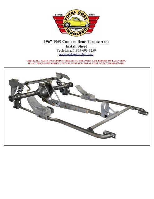
<strong>1967</strong>-<strong>1969</strong> <strong>Camaro</strong> <strong>Rear</strong> <strong>Torque</strong> <strong>Arm</strong><strong>Install</strong> <strong>Sheet</strong>Tech Line: 1-855-693-1259www.totalcostinvolved.comCHECK ALL PARTS INCLUDED IN THIS KIT TO THE PARTS LIST BEFORE INSTALLATION.IF ANY PIECES ARE MISSING, PLEASE CONTACT: TOTAL COST INVOLVED 866-925-1101
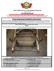
67 [429-4202-00] OR 68-69 [429-4202-00] REAR BRACKETS BARS ShocksIncludes: Includes: Includes: Includes:1 REAR C/O CROSSMEMBER 1 DRV SIDE BKT 2 18 ½ * 1 ¼ 2 All-American C/O1 BOLT-ON PANARD BRACKET 1 PAS SIDE BKTPerformance Bars Shocks2 RE-ENFORCEMENT PLATES 1 DRV SIDE TOP PLT w/ bushings 2 5/8-18 * 4 ½”Bolts2 SHOCK BLOCK OFF PLATES 1 PAS SIDE TOP PLT 2 ¾ Stainless 2 5/8-18 * 5 ½” Bolts1 WELD-ON PANARD BRACKET 32 5/16-24 * 1 ¼ SBCH Adjustors w/ jams& bushings2 Upper 5/8” Spacer2 Lower 2 3/8” Spacer4 5/16-24 * 1 ¼ SBCH note (67 will have 8) 32 5/16-24 NYLOX 1 Panard BarAxle Brackets4 5/16-24 NUT NYLOX note (67 will have 8) 32 ¼ USS WASHERS Reg = 39”Pro = 37”2 <strong>Torque</strong> <strong>Arm</strong> AxleBrackets4 5/16 FLAT WASHERS note (67 will have 8) 4 3/8-16 * 1” BOLTS 4 5/8-18*2 ¾ SBCH <strong>Torque</strong> <strong>Arm</strong> Assembly4 5/16 -18 * ¾ SBCH 2 3/8-16 * 1 ¼” SHCS 4 5/8-18 ½ NYLOX 1 Main <strong>Torque</strong> <strong>Arm</strong>4 5/16 LOCK WASHERS 1 3/8 Drill Guide 1 5/8 RH Heim w/jam 1 Slider Assembly4 3/8 -24 * 3” HEX G8 4 3/8 -16 * 3 ½” HEX G83/8-24 * 3” G8 (PRO)1 5/8 LH Heim w/jam 1 TA Cross member w/Drive Shaft loop4 3/8 24 NUT NYLOX 4 3/8-16 NUT, PLAIN3/8-24 ½ NYLOX(PRO)2 ½-20 * 2” G8 2 Pinion Support Tubes13 3/8 x ¾ inch8 3/8 FLAT WASHERS 6 3/8 LOCK WASHERS 2 ½-20 NYLOX 2 ½ RH Heim w/jam8 3/8 FLAT WASHERS 4 ½ Flat Washers 2 ½ LH Heim w/jam<strong>Torque</strong> <strong>Arm</strong> Assembly Continued1 <strong>Torque</strong> Tab Location Tool 1 Reg Hsg <strong>Torque</strong> Tab Kit 1 Top pinion support spacer ¾ x 5.2”1 <strong>Torque</strong> <strong>Rear</strong> Location Tool 1 F9 Hsg <strong>Torque</strong> Tab Kit 2 Lower pinion support spacers 1¼ x 1½“2 ½ -20 Full Nylox 4 ½ Flat Washers 2 ½ -20 x 8” G8 Pinion support T & BSUBFRAME CONNECTORSOptionsIncluded with <strong>Torque</strong> <strong>Arm</strong> SHOCKS Bar Kit SWAY BAR KITTCI CONV [429-4622-00] Chrome All-American Chrome or PolishedBar Kit (Link & Panard)¾” Sway Bar KitPlain or ChromeTCI COUP [429-4621-00]Billet Adjustable C/O PlainSTK CONV [429-4624-00]STK CONV [429-4623-00]Billet Adjustable C/O PolishedComplete <strong>Rear</strong> End Assembly w/ BrakesThe car needs to be securely positioned on tall jack stands or preferably a hoist to facilitate removal of the oldcomponents. Temporarily remove the rear seat and the carpet in the area that the floor will be drilled through.The 2/4 link bracket is installed first. Any high spots on the floor pan will have to be ground flush so thebracket will set flat against the body when bolted up to the original front leaf spring hanger holes.Position the brackets with the curved end rearward going up the floor pan and the channel aligned over theframe rail. <strong>Install</strong> the 2 hex head 3/8 x 1 inch bolts on the front and frame channel using flat washers and lockwashers. Leave bolts partial loose to facilitate installing the 3/8 x 16 x 1¼ socket head bolt with lock washer onthe outside hole up inside of the bracket. This can be a little tricky as the nut is on a clip that wants to movearound. I ground a slight point on the bolt to help center the inside nut. With the socket headed bolt tight finishtightening the rest of the bolts.
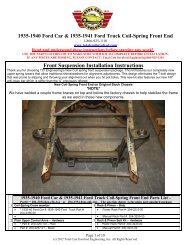
The flange on the outer rail will have to have a radiusfor clearance to install the link bolt if the top hole isto be used. When the link bar is installed in the tophole the bar will be angling down toward the rearaxle bracket and as the car rolls on that side whenmaking a turn the front of the bar will move downpushing the rear axle rearward inducing rear rollsteer which is desirable in cornering. With the bar inthe lower bracket hole roll steer is eliminated butforward bite is increased. The bracket shown is for atwo inch inset mini-tub application.Next using the 5/16 inch bracket holes as a guide,drill one 5/16 hole through the floor pan and installone of the 5/16 x 1¼ x 24 button head bolts andinstall nut on inside and tighten. This will keep thebracket from moving around while drilling and allholes will line up when finished. Finish drillingremainder of the holes using a long shank 5/16 inchdrill bit.Align the appropriate curved re-enforcing plate onthe inside of the car over the drilled bolt holes andhave a second person push the 5/16 button headedbolts through the bracket underneath. <strong>Install</strong> thewashers and the 5/16 Nylock nuts and tighten.Note: You may have to grind a flat on the side of thebolt head because a few of the holes are close to theinside of the bracket.
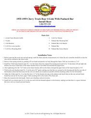
Using a 3/8 inch drill bit and using the 3/8 inch holesin the channel bracket, drill the inside holes throughthe frame rail. Then using the furnished drill guide,align the drill bit in the guide with the drill bit in thepreviously drilled hole and clamp the guide aspictured. This will facilitate in keeping the drill bit inline with the outside holes in the bracket.<strong>Install</strong> the four 3/8 x 16 x 3 ½ inch bolts washersand Nylock nuts. Note: On mini-tub applications use3 inch long bolts with ½ nuts. With the link bar boltinstalled the clearance is tight.<strong>Install</strong> the 1¾ neoprene end caps in the sub-frameconnectors. If using a TCI front clip, position theconnector tube as shown and install the front ½ x 20x 3½ inch bolts with the bolt heads on the inside ofthe clip tube and the nuts go on the curved receiverside of the connector tube. The rear bolts takewashers on both sides and go through the bracketwith the nuts on the inside. Bolting on the connectorsfor a stock clip will require drilling six 3/8 holesusing a furnish template. Comes with an inside reenforcingplate and hardware.The coil-over cross-member is next. Remove anyhanger brackets that will interfere.On the <strong>1967</strong> <strong>Camaro</strong>, the cross-member is installedup flush with the rear frame rails and measured 133/16 inches from the flat vertical body panel to thefront edge of the cross-member. The ends of thecross-member are angled in at the front.The 1968-69 <strong>Camaro</strong> coil-over cross-member islocated by the two existing 3/8 x 16 threaded holes inthe frame rail. Using the four 3/8 x 16 x 1 inch bolts,fasten the front flange of the cross-member to theframe and push the saddle of the cross-member flushbefore tightening.With the channel bracket pressed flush against theframe rail, use a 3/8 drill bit and drill the two outsideholes in each frame rail using the holes in the channelbracket as a guide.Using the drill bushing guide over the previouslydrilled hole, clamped the guide to the bracket, drillhorizontally through the other side of the frame andthrough the hole in the bracket.Finish by installing the four 3/8 x 16 x 3 inch bolts,washers and Nylock nuts and tighten.
Using the 5/16 inch holes on the flange of the channelbracket as a guide, use a long shank 5/16 drill bit anddrill the 4 holes (2 on 68-69) through the floor of thetrunk.<strong>Install</strong> the 4 hole re-enforcing plate (2 hole on 68-69)over the holes and install the 5/16 x 24 x 1¼ inchbutton head bolts and washers through the plate,trunk sheet metal and through the cross-memberchannel bracket.<strong>Install</strong> the 5/16 Nylock nuts and tighten.Top photo: <strong>1967</strong> <strong>Camaro</strong>Bottom photo 1968-69 <strong>Camaro</strong>The <strong>Torque</strong> <strong>Arm</strong> cross-member is installed with thedriveshaft loop facing rearward and the end flangesof the cross-member under the brackets on the subframeconnectors. Using the 3/8 x 16 x 1 inch boltsand washers, bolt the cross-member to the sub-framebrackets and install the 3/8 Nylock nuts and washers.Double check to make sure that the driveshaft loop iscentered in the driveshaft tunnel before finaltightening.When installing the optional ¾ inch rear sway bar,first slide the lock rings on. Next the split urethanebushing with flange facing lock ring. Next thebrackets with the flange facing rearward and thesway bar forward. Leave lock rings loose to facilitateinstall. <strong>Install</strong> the four 3/8 x 2½ bolts, washers andNylock nuts. Adjust sway bar location after rear axleis installed. Note: We mounted the fuel filter andpump to the cross-member.
<strong>1967</strong>-69 <strong>Camaro</strong>Housing width stock tub-------53½ inches: Axle flange to axle flange 58 ½ inchesHousing width mini-tub---50 ½ inches: Axle flange to axle flange 55½ inches1968-72 NovaHousing width stock tub-------52 ½ inches; Axle flange to axle flange 57½ inchesHousing width mini-tub--50 ½ inches: Axle flange to axle flange 55 ½ inchesThe axle brackets are designed to slide over a 3 inchaxle tube before the bearing flange housings areinstalled. If the bearing ends are already on the axlebracket 3 inch ribs can be cut 90 degrees to the flatshock mounting face and re-attached after thebracket is tacked on. The brackets are positioned 441/8 centers for stock width and 40 1/8 for the 2 inchmini-tub.The flat rear surface of the axle bracket needs to beparallel with the front mounting surface of the 3 rdmember. (aka 0 pinion angle)The panhard bar bracket is installed onto the back ofthe driver’s side axle bracket with the channel facingout and the inner curved radius inside the outer axlebracket rib up against the 3 in axle tube rotateddown against the rear face of the axle bracket.
The torque arm tabs are welded on by using thesupplied fixture tool. Bolt fixture to the lowest 2 thirdmember bolts flat against the housing flange. Bolt onthe two supplied tabs using the ½ by 3½ inch bolt andwith the longer tab to the passenger side of thehousing. Bottom of tabs may need sanding to fit.Weld outside and wrap welds also to the inside.Finish welding the axle brackets and the panard barbracket as pictured. If an optional sway bar is beingused the sway bar brackets are located on the frontof the axle tubes at axle centerline on 33 inch centers.The pinion support brackets are installed next. Usingthe furnished fixture tool, using the three 3/8 by 24nuts, bolt the fixture onto the top three studs of thethird member housing with the locating tabs facingforward. Bolt the ¼ inch laser cut brackets to theoutside of the fixture tool using the two ½ inch boltswith the wider bracket on the passenger side and theshorter bracket on the driver side. Note; Some fittingmay be required to get the bracket flush with the topof the third member. The distance between the 2brackets should be 6.45 inches after welding. Becauseof the distortion from welding the housing will needto be straightened at this time.
The <strong>Torque</strong> <strong>Arm</strong> is shipped with the slider assemblyseparate to facilitate packaging. The slider has preassembledwith Teflon bushings and has beeninstalled in the <strong>Torque</strong> <strong>Arm</strong> to check for proper fit.We use anti-seize on the threads to prevent galling.When painting or powder coating the assembly, tapethe threads on the slider and plug the hole in the<strong>Torque</strong> <strong>Arm</strong> tube.<strong>Install</strong> the slider into the <strong>Torque</strong> <strong>Arm</strong> using antiseizeand be careful not to cross thread and tighten. Iused a vise and a 12 inch crescent wrench to makesure it was tight.<strong>Install</strong> the rear of the <strong>Torque</strong> <strong>Arm</strong> to the tabs on thebottom of the rear end housing using a ½ inch by 3½inch bolt, washers and nut. Lightly tighten.
The pinion support tubes have left and right handrod ends to facilitate pinion angle adjustment. Adjustthe tubes to approximately the same length with anequal amount of threads showing on each rod end.<strong>Install</strong> the tubes with the right hand rod ends on theinside of the top brackets using the ½ by 8 inch bolt,washers, 5.2 inch spacer in between rod ends andNylock nut.The left hand end of the tube is installed on the insideof the <strong>Torque</strong> <strong>Arm</strong> bracket with the spacer betweenthe rod end and the <strong>Torque</strong> <strong>Arm</strong> tube. <strong>Install</strong> the ½by 8 inch bolt through the bracket, rod ends, tubeand spacers. <strong>Install</strong> Nylock nut and tighten. Now,tighten the nut on the bottom of the housing.Note: On our 68 <strong>Camaro</strong> with 2½ inch exhaust andFlowmaster mufflers, I had to unbolt the lower endof one of the pinion support tubes to allow enoughclearance to get the 3½ inch drive shaft installed thenreconnect the pinion tube. To adjust the pinion angleafter installation is complete; the tubes can berotated simultaneous clockwise to raise the pinion orcounter-clockwise to lower the pinion. I adjusted thepinion one degree down from the drive shaft. Tightenlock nuts top and bottom.The slider shaft travels in and out very little but stillneeds to be positioned in the slots 6¼ inches from theback of the wrench flats on the housing to the centerof the sleeve with the bushing in it. This adjustmentallows the slider shaft to be in the middle of its travel.Tighten the Nylock nut.
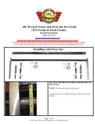
The slider is installed and centered. The <strong>Torque</strong> <strong>Arm</strong>cross-member has exhaust cut out relief’s to allowthe exhaust pipes to be tucked up higher for moreground clearance.The photo on the left shows the panard bar attached to the axle housing bracket using ½ x 20 x 2 inch bolt,washers and Nylock nut. The process is repeated on the right side on the panard bar bracket that is bolted tothe coil-over cross-member. The three hole adjustment gives the choice of raising or lowering the rear rollcenter.Finish the project by installing the shock hole block off plates using the four 5/16 x 18 x ¾ button head bolts.
The <strong>Torque</strong> <strong>Arm</strong> rear suspension completely installed. The TCI <strong>Camaro</strong> uses 2½ inch exhaust system andFlowmaster mufflers. Everything is tucked up close and tight so installing the driveshaft should be done beforeinstalling exhaust system and leaving one of the pinion support tubes off until the driveshaft is installed.No returns or exchanges without a RMA#.Packages must be inspected upon receipt & be reported within 10 days.If you are missing parts from your kit, TCI Engineering will send the missing parts via FedEx or U.S. mail ground.Returned packages are subject to inspection before replacement/refund is given.(Some items will be subject to a15% restocking fee)Thank you for your business!