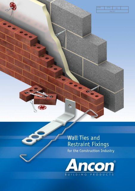
Wall Ties and Restraint Fixings - Masonry First
Wall Ties and Restraint Fixings - Masonry First
Wall Ties and Restraint Fixings - Masonry First
- No tags were found...

You also want an ePaper? Increase the reach of your titles
YUMPU automatically turns print PDFs into web optimized ePapers that Google loves.
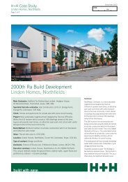
<strong>Wall</strong> <strong>Ties</strong> <strong>and</strong> <strong>Restraint</strong> <strong>Fixings</strong>4© Green Building Store © Irvine Whitlock© Hazle McCormack YoungCAVITY WALL TIE SELECTIONThe selection <strong>and</strong> spacing of wall ties dependon many factors. These include type ofmasonry to be tied, cavity width, type <strong>and</strong>height of building, location, <strong>and</strong> design life.There are several documents which need to beconsulted <strong>and</strong> are summarised here.Eurocode 6 – Design of <strong>Masonry</strong>Structures (BS EN 1996-1-1: 2005)In 2010, Eurocode 6 became the main codefor the design of reinforced <strong>and</strong> unreinforcedmasonry. Eurocode 6 refers to EN 845-1 forwall ties <strong>and</strong> sets the density of ties per squaremetre based on the declared value of the tie,the material factor <strong>and</strong> the design wind load.BS EN 845-1: 2003 Specification forAncillary Components for <strong>Masonry</strong> –Part 1: <strong>Ties</strong>, Tension Straps, Hangers <strong>and</strong>BracketsThis European St<strong>and</strong>ard specifies therequirements for wall ties used forinterconnecting masonry <strong>and</strong> for connectingmasonry to beams, columns or other partsof the building. Materials, tolerances, tievariations <strong>and</strong> the requirements for declaredvalues, are all covered in this st<strong>and</strong>ard. For tieTypes <strong>and</strong> qualifying criteria refer to PD 6697:2010.PD 6697: 2010 Recommendations for thedesign of masonry structures to BS EN1996-1-1 <strong>and</strong> BS EN 1996-2Published Document 6697 contains noncontradictory,complementary informationfrom the withdrawn British St<strong>and</strong>ard BS 5628,which was not included in the BS EN 1996series.It includes recommendations on tie lengths,embedment, density, material <strong>and</strong> positioning.<strong>Masonry</strong>-to-masonry ties are classified asTypes 1 to 4; the relevant classification isdetermined by strength, function <strong>and</strong> use.Minimum declared values for tension <strong>and</strong>compression are listed on page 5 for each tieType.Approved Document E: Resistance to thePassage of SoundThis document specifies the acousticperformance requirements of ties suitable foruse in separating walls (Type A) <strong>and</strong> externalwalls (Type B) of new build dwellings.Type A ties must have a measured dynamicstiffness of
Tel: +44 (0) 114 275 5224 Web: www.ancon.co.ukMinimum Requirements for <strong>Wall</strong> <strong>Ties</strong> to PD 6697: 2010 (Table 12) <strong>and</strong> BS 5268-6.1: 1996 (Annex B)Type Minimum Mortar Tensile Load Compressive Loadof Tie Class <strong>and</strong> Designation Capacity (N) Capacity (N)1M12 (i) 5000 5000M2 (iv) 2500 25002 M2 (iv) 1800 13003 M2 (iv) 1100 8004 M2 (iv) 650 4505 M4 (iii) 600 4256 M4 (iii) 630 4407 M4 (iii) To be declared by the <strong>Wall</strong> Tie Manufacturer<strong>Masonry</strong>-to-<strong>Masonry</strong> <strong>Wall</strong> Tie Types to PD 6697: 2010Maximum BuildingType Application Density Height Geographical LocationType 1 Heavy duty tie suitable for most 2.5 ties/m 2 Any Height Suitable for most sites. However, forbuilding sizes <strong>and</strong> types. 3-4 ties/m 2 relatively tall or unusually shaped buildingsNot very flexible <strong>and</strong> not at unbonded in vulnerable areas, the tie provisionrecommended for applications where edges should be calculatedthere is expected to be excessivedifferential movement between leavesType 2 General purpose tie for domestic <strong>and</strong> As Type 1 15m Suitable for flat sites where the basicsmall commercial buildings.wind speed is up to 31m/s <strong>and</strong> altitudeis not more than 150m above sea levelType 2 ties are suitable for use outside the parameters stated e.g. sites over 150m above sea level, buildings exceeding 15 metres etc,if shown to be adequate by calculation. Contact Ancon for more information.Type 3 Basic wall tie generally as As Type 1 15m Suitable for flat sites where the basicType 2 abovewind speed is up to 27m/s <strong>and</strong> altitudeis not more than 150m above sea levelType 4 Light duty wall tie suitable for As Type 1 10m Suitable for flat sites in towns <strong>and</strong> citiesbox-form domestic dwellingswhere the basic wind speed does notwith leaves of similar thicknessexceed 27m/s <strong>and</strong> altitude is not morethan 150m above sea levelNote: Refer to PD 6697: 2010 <strong>and</strong> BS EN 1991-1-4: 2005 for complete information.≤ 31m/s≤ 27m/sWind speed information taken fromBS EN 1991-1-4: 2005 for use withPD 6697: 2010.Ancon Teplo4(Type 4)Ancon ST1(Type 1)Staifix RT2(Type 2)Staifix RT3(Type 3)Staifix HRT4 (Type 4)Suitable for use in internalseparating walls toApproved Document EAncon Teplo1(Type 1)Ancon Teplo2(Type 2)Staifix-ThorHelical TIM6(Type 6)Staifix STF6(Type 6)Ancon Timber FrameMovement Tie, TFMT7(Type 7)≤ 31m/s<strong>Masonry</strong>-to-Timber Tie Types to BS 5268-6.1: 1996Maximum BuildingType Application Density Height Geographical LocationType 5 Timber frame tie suitable for 4.4 ties/m 2 15m Suitable for flat sites in towns <strong>and</strong> citiesdomestic houses <strong>and</strong> industrial/ 3-4 ties/m where the basic wind speed does notcommercial developments of up at unbonded exceed 25m/s <strong>and</strong> altitude is not moreto three storeys edges than 150m above sea levelType 6 As Type 5 but suitable for As Type 5 15m Suitable for flat sites in towns <strong>and</strong> citiesdevelopments of up to fourwhere the basic wind speed does notstoreysexceed 25m/s <strong>and</strong> altitude is not morethan 150m above sea levelType 7 As Type 5 but suitable for Calculated for 18m Calculated for actual performancedevelopments of between five actual required for each site location<strong>and</strong> seven storeys, beingperformancedesigned to accommodaterequired forthe increased verticaleach site locationdifferential movementNote: Refer to BS 5268-6.1: 1996 <strong>and</strong> BS 6399-2: 1997 for complete information.≤ 31m/s≤ 25m/sWind speed information taken fromBS 6399-2: 1997 Code of Practice forWind Loads for use with BS 5268-6.1: 1996.5
<strong>Wall</strong> <strong>Ties</strong> <strong>and</strong> <strong>Restraint</strong> <strong>Fixings</strong>WALL TIES TO PD 6697 FORBRICK-TO-BLOCK CONSTRUCTIONAncon ST1 Type 1 Tie(<strong>Masonry</strong> Heavy Duty)The Ancon ST1 is suitable for cavities from50mm to 175mm <strong>and</strong> can be used for alltypes of buildings of any height, anywhere inthe British Isles. The section that spans thecavity has a series of holes to provide waterdrips. The ST1 has a measured dynamicstiffness of
Tel: +44 (0) 114 275 5224 Web: www.ancon.co.ukAncon TeploTieThe Ancon TeploTie is suitable for cavities from50mm to 300mm <strong>and</strong> is manufactured frompultruded basalt fibres set in an epoxy resin.This material has a thermal conductivity of only0.7W/mK which can be shown in U-valuecalculations to reduce insulation thickness <strong>and</strong>wall footprint. A s<strong>and</strong> finish provides excellentmortar key.The Ancon range of Teplo<strong>Ties</strong> comprisesTeplo1 (Type 1), Teplo2 (Type 2) <strong>and</strong> Teplo4(Type 4). Please refer to page 5 for furtherdetails on the suitability of each wall tie. Dueonly to the testing completed to date, the useof Type 1 Teplo<strong>Ties</strong> is restricted to buildings upto 18m in height. Contact Ancon for the latestinformation on this test programme.Ancon Teplo<strong>Ties</strong> have BBA approval <strong>and</strong> meetthe technical requirements of the NHBC. Theyalso meet the performance requirement ofApproved Document E for use in externalmasonry walls. For internal separating wallsof new-build attached dwellings see HRT4.The TeploTie is exclusive to Ancon in the UK<strong>and</strong> Irel<strong>and</strong>. It has already been used on manyultra energy efficient buildings including the firstcertified PassivHaus to be built with traditionalmasonry cavity walls <strong>and</strong> the first retrofit to bebuilt to Level 6 (Zero Carbon) of the Code forSustainable Homes.Teplo<strong>Ties</strong> can be resin-fixed in remedial <strong>and</strong>retrofit applications. Further details are shownon page 29-30.Low Thermal Conductivity <strong>Wall</strong> <strong>Ties</strong><strong>Wall</strong> ties are an essential element in thestrength <strong>and</strong> stability of cavity walls, but bycrossing the cavity they act as a thermalbridge between the internal <strong>and</strong> externalleaves. The ties featured here on pages 8-9form Ancon’s Low Thermal Conductivity range;ties which minimise heat loss <strong>and</strong> improve theenergy-efficiency of a masonry wall. The effectAncon’s high tensile wire wall ties have on heattransfer is negligible <strong>and</strong>, with a thermalconductivity of only 0.7W/mK, the AnconTeploTie is the most thermally-efficient wall tieon the market.For the accurate calculation of a wall’s U-valueit is important to use the correct information forthe wall ties. Using the actual cross-sectionalarea <strong>and</strong> thermal conductivity value of a walltie, rather than allowing a program to applydefault values, can make a considerabledifference to the calculated U-value. Defaultvalues will over-estimate the effect of an Ancon<strong>Wall</strong> Tie.Ancon Teplo1, Basalt-Fibre200mm for 50-75mm cavities225mm for 76-100mm cavities250mm for 101-125mm cavities275mm for 126-150mm cavitiesAncon Teplo2, Basalt-Fibre200mm for 50-75mm cavities225mm for 76-100mm cavities250mm for 101-125mm cavities275mm for 126-150mm cavities300mm for 151-175mm cavities325mm for 176-200mm cavities350mm for 201-225mm cavities375mm for 226-250mm cavities400mm for 251-275mm cavities425mm for 276-300mm cavitiesAncon Teplo4, Basalt-Fibre200mm for 50-75mm cavities225mm for 76-100mm cavities250mm for 101-125mm cavitiesAncon Teplo4(Type 4)Ancon Teplo2(Type 2)Ancon Teplo1(Type 1)Cross-Sectional Areas <strong>and</strong> Thermal Conductivity of Ancon <strong>Wall</strong> <strong>Ties</strong>ThermalTie Reference Tie Length Cavity Width Tie Type to Area Conductivity*(mm) (mm) PD 6697 (mm 2 ) (W/mk)200 50-75 1 19.5 17225 76-100 1 19.5 17ST1 250 101-125 1 19.5 17275 126-150 1 23.4 17300 151-175 1 23.4 17200 50-75 2 7.5 17RT2 225 76-100 2 7.5 17250 101-125 2 8.6 17200 50-75 3 6.2 17RT3 225 76-100 3 6.2 17250 101-125 3 7.5 17200 50-75 4 3.5 17HRT4 225 76-100 4 4.2 17250 101-125 4 6.2 17275 126-150 4 6.2 17200 50-75 1 38.5 0.7Teplo1 225 76-100 1 38.5 0.7250 101-125 1 38.5 0.7275 126-150 1 38.5 0.7200 50-75 2 19.6 0.7225 76-100 2 19.6 0.7250 101-125 2 19.6 0.7275 126-150 2 28.3 0.7Teplo2 300 151-175 2 28.3 0.7325 176-200 2 28.3 0.7350 201-225 2 38.5 0.7375 226-250 2 38.5 0.7400 251-275 2 38.5 0.7425 276-300 2 38.5 0.7200 50-75 4 12.6 0.7Teplo4 225 76-100 4 12.6 0.7250 101-125 4 12.6 0.7Note: BS EN ISO 6946 permits the corrections due to wall ties, air gaps etc to be omitted, if the corrections amount toless than 3% of the uncorrected U-value of the element. * <strong>Wall</strong> <strong>Ties</strong> with a thermal conductivity of less than 1.0W/mK areexcluded from U-value calculations to EN ISO 6946, irrespective of cross-sectional area.9
<strong>Wall</strong> <strong>Ties</strong> <strong>and</strong> <strong>Restraint</strong> <strong>Fixings</strong>TIES FOR CAVITIES OVER 150MMAncon Two-Part TieCavities exceeding 150mm are sometimesrequired. This necessitates longer ties whichcan be difficult to balance <strong>and</strong> keep horizontalwhen built into the inner leaf. Alternatively, theAncon Two-Part Tie has one section built intothe blockwork; the other section is then fixedas the outer leaf is built. An embedment of75mm is required at each end. The inner tie isusually manufactured in lengths of 170mmwith variation in the cavity width beingaccommodated by the length of the outersection. Where insulation thickness is inexcess of 60mm, the inner section should belonger than the st<strong>and</strong>ard 170mm to ensure theconnection between the two parts is made inthe open cavity.Ancon Two-Part <strong>Ties</strong> sustain loads whichexceed the requirements for a Type 2 tie toPD 6697 for cavities up to 300mm. Type 2performance can be achieved for widercavities providing the fixing centres areadjusted in accordance with the table below.Inner Section170mmas st<strong>and</strong>ardTo specify or order this tie simply quote ‘AnconTwo-Part Tie to suit _ _ _mm cavity with aninsulation thickness of _ _ _mm’. The black TJInsulation Retaining Clip is recommended foruse with the inner section.Recommended Fixing Centres forTwo-Part <strong>Ties</strong>Outer SectionLength to suitapplicationU.K. Patent No.2 265 920Cavity Vertical Horizontal(mm) centres (mm) centres (mm)150-300 450 900301-333 450 750334-367 450 600368-400 450 450Connection tobe made in theopen cavity75mmInsulationDepth75mmAncon TeploTieAncon Teplo2 (Type 2) wall ties are available tosuit cavities up to 300mm. They have athermal conductivity of only 0.7W/mK, areBBA approved <strong>and</strong> meet the technicalrequirements of the NHBC. These ties aresuitable for use with partial-fill <strong>and</strong> full-fillcavities.<strong>Wall</strong> Tie PD 6697 Length Cavity RangeReference Type (mm) (mm)Teplo2 2 200 50-75Teplo2 2 225 76-100Teplo2 2 250 101-125Teplo2 2 275 126-150Teplo2 2 300 151-175Teplo2 2 325 176-200Teplo2 2 350 201-225Teplo2 2 375 226-250Teplo2 2 400 251-275Teplo2 2 425 276-300CavityANCON SLIP-BRICK TIESAncon Slip-Brick <strong>Ties</strong> arebolted directly to blockwork orconcrete to give both support<strong>and</strong> restraint to thin slip brickfacings.In addition to the st<strong>and</strong>ardthree brick version, slip brickties can be manufactured inother multiples on request.10
Tel: +44 (0) 114 275 5224 Web: www.ancon.co.ukTIES FOR STEEL STUDWORKAncon 25/14 <strong>Restraint</strong> SystemThe Ancon 25/14 system is designed to tiebrickwork to steel studding. Self-drilling screwsfix through the channel <strong>and</strong> the rigid insulationboard, into the steel. Once the channel isinstalled, Ancon SD25 wall ties can bepositioned at any point along its length <strong>and</strong> arebuilt into the bed joints of the outer leaf ofbrickwork.The spacing of ties is based on the height ofthe building <strong>and</strong> its geographical location.This system has a performance in excess ofType 3 <strong>and</strong> the table below should be used inconjunction with the first wind speed map onpage 5.Tie Spacing Based on 25/14 Channel at600mm Horizontal Centres with Basic WindSpeed < 27m/sVertical Tie Spacing(mm) for VariousAltitude <strong>and</strong> DistanceHeights of Brickworkfrom the Coast 15m 25m 40mAltitude up to 150m <strong>and</strong> atleast 50km from coast450 225 225Altitude up to 25m <strong>and</strong> within50km from coast450 300 225Ancon recommends that wall ties achieve aminimum embedment of 62.5mm in the outerleaf of brickwork. Applications with a 50mmopen cavity require 100mm long ties.25/14 channel is available in lengths of2700mm <strong>and</strong> 3000mm. It features prepunchedholes at close centres to ensure afixing position is always located near the end,even when it is cut on site. It should be fixedto steel studwork at 450mm vertical centres.14mm16mm25mm25/14 Channel ProfileScrews are available to accommodate aninsulation thickness of up to 115mm. Anconrecommends the use of stainless steel fixingscrews.The channel has a 16mm opening toeasily accommodate a drive socket <strong>and</strong>washer for the fixing screws.This system has been independently tested atCERAM Building Technology <strong>and</strong> meets thetechnical requirements of the NHBC.Note: This system is unsuitable for use with flexible orsemi-rigid insulations. Contact Ancon for furtherinformation.Ancon 25/14 Channelwith SD25 <strong>Wall</strong> TieSelf-Drilling Screw Ref. HTSS-65-2PT HTSS-82-2PT HTSS-115-2PT HTSS-135-2PTMaterial Stainless Steel Stainless Steel Stainless Steel Stainless SteelDiameter (mm) 5.5 5.5 5.5 5.5Length (mm) 65 82 115 135Insulation Thickness (mm) 35-50 50-70 70-95 95-11511
<strong>Wall</strong> <strong>Ties</strong> <strong>and</strong> <strong>Restraint</strong> <strong>Fixings</strong>TIES FOR THIN-JOINT BLOCKWORKStaifix-Thor Helical TJ2 <strong>Wall</strong> TieThe TJ2 wall tie hammers directly into aeratedconcrete blocks, through insulation material,<strong>and</strong> is built into the bed joints of the outer leafof brickwork. It is ideal for thin-joint blockwork<strong>and</strong> other applications where the joints in theinner <strong>and</strong> outer leaves are not aligned. This tiemeets the requirements of the NHBC <strong>and</strong>PD 6697 as a type 2, 3 or 4 wall tie dependingon the block used <strong>and</strong> the cavity width. Toolsare available to simplify installation.TJ2 to PD 6697Block Strength Tie Type to PD 6697N/mm 2 50, 75, 100mm Cavity 125, 150mm Cavity2.8 4 43.5 - 4.0 3 47.0 - 10.5 2 3Note: For maximum building height <strong>and</strong> restrictions based on geographical location please refer to page 5.The helix of the Staifix-Thor Helical range issuperior to other helical fixings. Each rotationinterlocks perfectly down its lengthguaranteeing maximum performance.85mm70mmThe black Staifix TJ Clip is designed for usewith TJ2 wall ties.Staifix HRT4 <strong>Wall</strong> TieFor thin-joint to thin-joint separating walls usethe Staifix HRT4 (see page 8).<strong>Ties</strong> for Cellular Clay BlocksAncon has developed an innovative range ofwall ties for use with cellular clay blockwork,where the horizontal bed joints are just 1mm.The range includes cavity wall ties for use withexternal brickwork, cavity wall ties for internalseparating walls to Approved Document E <strong>and</strong>ties for connecting perimeter walls to internalwalls.Installation of the component parts of cavitywall ties in this range are phased whicheliminates any danger of injury from wall tiesprojecting from a part-built cavity wall.Cellular Clay Block to Traditional <strong>Masonry</strong>Staifix-Thor Helical TJ2 Thin-Joint TieEuropean Patent No. 1307303CCB3-100CCB3-125CCB4-150Embedment DepthsTJ2 Recommended LengthsCavity Width (mm)Tie Length (mm)50 20575 230100 255125 280150 305CCBA-75CCB-IWJ-180Cavity Width Product Type 4 Type 3 Type 2(mm) Reference Performance Performance PerformanceHorizontal x Vertical Spacings (mm)100 CCB3-100 900 x 450 900 x 450 600 x 450125 CCB3-125 900 x 450 900 x 450 600 x 450150 CCB4-150 900 x 450 450 x 450 -Notes: At vertical edges of an opening, unreturned or unbonded edges, additional ties should be used at a rate of oneper 300mm height, located not more than 225mm from the edge. For complete information on tie types refer toPD6697: 2010. Tested to EN845-1:2003.Cellular Clay Block to Cellular Clay Blockfor Internal Separating (Party) <strong>Wall</strong>sAncon CCB3 <strong>Wall</strong> TiePatent pendingCavity Width Product Horizontal x Vertical(mm) Reference Spacings (mm)75 CCBA-75 900 x 450Note: Type A tie suitable for use in internal separatingwalls of any height to Approved Document E: Resistanceto the Passage of Sound.12<strong>Ties</strong> for Internal <strong>Wall</strong> JunctionsFlat Tie for connecting perimeter walls tointernal wallsProduct ReferenceLength (mm)CCB-IWJ-180 180Note: For block widths greater than 140mm, two tiesshould be used per course.
<strong>Wall</strong> <strong>Ties</strong> <strong>and</strong> <strong>Restraint</strong> <strong>Fixings</strong>FRAME CRAMPS AND CHANNEL TIESFrame cramps can be fixed to concrete,steelwork or masonry <strong>and</strong> have a single 7mmdiameter hole or an 8mm x 30mm vertical slot.Ancon M6 Single Expansion bolts arerecommended for fixing to concrete, setscrews or self-drilling screws for steelwork,<strong>and</strong> suitable plugs <strong>and</strong> screws for fixing tomasonry.Poor substrates will limit the capacity of framecramps <strong>and</strong> site testing may be advisable insome cases. The performance will also bedetermined by the position of the fixing. SDVties fixed to steelwork or concrete at thelowest point of the slot will have a safe workingload of approximately 1kN. The capacity willreduce as the fixing is moved further awayfrom the bend <strong>and</strong> greater movement must beexpected than with other types of wall tie.Ancon SDB Frame Cramps have a safeworking load of approximately 500N,comparable to the load of an SDV when fixedin the centre of the slot.Thermal BreakAncon Frame Cramps can now be suppliedwith Thermal Breaks to be located betweenthe upst<strong>and</strong> <strong>and</strong> the structural frame. They aremanufactured from a durable fibre-reinforcedthermoset plastic which has a thermalconductivity of just 0.3 W/mK.SDB <strong>Wall</strong> TieSDV <strong>Wall</strong> Tie90mm90mmN10009008007006005004003002001000SDVFixing atbottom of slotSDVFixing incentre of slotRecommended Safe Working Loads for 20 x 2.5mm Section Frame CrampsRecommended Lengths of Frame Cramps <strong>and</strong> Channel <strong>Ties</strong>Cavity Width (mm) Length of <strong>Wall</strong> Tie (mm) Frame Cramp/Channel Tie20-44 100 SPB/SP2145-69 125 SDB/SD2170-94 150 SDB/SD2195-119 175 SDB SD21120-144 200 SDB/SD21145-169 225 SDB/SD21SDVFixing attop of slotNote: Frame cramps should have a minimum embedment of 50mm in the outer leaf. Taking site tolerances into account,Ancon suggests tie lengths which achieve a greater embedment.7mm ø20mm30mm3mmFrame Cramp Thermal BreakEmbedment90mmLengthSDB <strong>Wall</strong> Tie Fixed to Steelwith Self-Drilling ScrewEmbedment90mmLengthSD21 <strong>Wall</strong> Tie Fixed into 21/18Omega Channel14
Tel: +44 (0) 114 275 5224 Web: www.ancon.co.ukIsolationAncon isolation sleeves <strong>and</strong> pads are suppliedblank for use with self-drilling screws to isolatestainless steel frame cramps from mild steel.Self-adhesive isolation pads are also availablefor _ _B (20 x 30mm) <strong>and</strong> _ _ V (25 x 50mm)referenced frame cramps.SPA Frame CrampWhere masonry is in line with a column flange,frame cramps can be supplied with an offsetangle section instead of an upst<strong>and</strong>. Thisangle allows the mechanical fixing to besuitably located. These ties are referencedSPA. They feature a 7mm hole as st<strong>and</strong>ard<strong>and</strong> can be used with a debonding sleeve ifrequired at a movement joint. The thickness,size <strong>and</strong> shape of the angle section aredesigned to suit each application. ContactAncon’s Technical Department for moreinformation.Ancon SPA frame cramp at450mm vertical centresIsolation SleeveLength to suitapplicationSPA Frame CrampAdhesive Isolation PadAngle to suitapplicationPRE-FIXING AIDSThe practice of pre-fixing frame cramps inadvance of masonry can accelerate thespeed of construction <strong>and</strong> provides anopportunity to check that wall restraintshave been located correctly <strong>and</strong> aresecurely fixed.Ancon Gauge Tape(Pre-fix Patent 2 256 223)Gauge Tape illustrates the st<strong>and</strong>ard 225mmbrick/block gauge <strong>and</strong> the fixing position offrame cramps. It is applied directly to thestructural frame (steel, concrete, timber ormasonry) to facilitate the pre-fixing of framecramps <strong>and</strong> to maintain accurate masonrycoursing.Ancon ISO-TW WasherThe ISO-TW washer enables Ancon slotendedframe cramps to be verticallyadjusted within the 30mm range of the slotto suit the exact location of mortar jointswithout affecting the integrity of the fixing.In addition, this washer prevents bi-metalliccorrosion by separating the frame crampfrom the structural frame <strong>and</strong> fixing screw.SPA Frame Cramp Fixed to Steel withM6 Isolated Set ScrewsAncon ISO-TW <strong>and</strong> Gauge TapeAncon HiT - Hammer-in TieThe Ancon HiT fixes masonry to concrete,dense blocks (>_7N/mm 2 ), non-perforated brickor hard stone. It can reduce the variety of tielengths required on site <strong>and</strong> speed the rate ofconstruction.The HiT is available in a st<strong>and</strong>ard length of310mm that is bent on site with a specialinstallation tool to suit all cavities up to150mm. Unlike conventional frame cramps itdoes not require a mechanical fixing, but ishammered into a plug.The Ancon HiT meets the requirements ofPD 6697 as a Type 2 tie. A neoprene 'O' ringmust be installed on the tie to prevent moisturecrossing the cavity.Ancon Hammer-in Tie (310mm)15
<strong>Wall</strong> <strong>Ties</strong> <strong>and</strong> <strong>Restraint</strong> <strong>Fixings</strong>Available Lengths of Ancon 21/18 Omega Channel100, 3000mmU.K Patent No. 2 249 110Ancon 21/18 Omega Channel with AnconSD21 TieAncon 21/18 Omega ChannelAncon 21/18 Omega Channel is a highperformance, self-anchoring, cast-in channelslot suitable for use with Ancon wall ties toprovide the necessary restraint to the outer leafof masonry. The section is only 18mm deep<strong>and</strong> can be used where there is reduced coverto reinforcement. Available in 100mm <strong>and</strong>3000mm lengths, Ancon 21/18 OmegaChannel is filled with polystyrene to helpprevent the ingress of concrete. Nail holes aidthe fixing of the slot to timber formwork. <strong>Wall</strong>ties used with Ancon 21/18 Omega Channelwill provide safe working shear <strong>and</strong> tensileloads of 1.5kN.Fixing of ChannelFixing Method Omega 21/18 25/14 28/15 30/20 38/17 36/8 40/25Cast-inSurface FixedMaximum Centres for Surface-FixingAncon 25/14, 28/15, 30/20, 38/17, 36/8 <strong>and</strong>40/25 ChannelsAncon wall ties can also be used with our25/14, 28/15, 30/20, 38/17, 36/8 <strong>and</strong> 40/25channels. 30/20 Channel is supplied withanchors for casting into concrete. 25/14 <strong>and</strong>36/8 Channels are supplied plain-backed forsurface fixing. 28/15, 38/17 <strong>and</strong> 40/25Channels are available with or without anchorsfor casting in or surface fixing. <strong>Ties</strong> for 38/17<strong>and</strong> 40/25 channel will be 25mm wide toaccommodate the wider opening; all otherchannel ties will be 20mm wide. <strong>Wall</strong> ties usedwith Ancon 28/15, 30/20, 38/17 <strong>and</strong> 40/25channel will provide safe working shear <strong>and</strong>tensile loads of up to 1.0kN, while wall tiesused with 25/14 <strong>and</strong> 36/8 channels will provideup to 0.5kN. Maximum safe working loads ofsurface-fixed channels will be subject tosuitable fixings, <strong>and</strong> appropriate fixing centres.✔ ✘ ✔ ✔ ✔ ✘ ✔✘ ✔ ✔ ✘ ✔ ✔ ✔SWL (tension) 25/14 28/15 38/17 36/8 40/250.5kN 337 525 650 300 6501.0kN - 400 525 - 525Fastrack used with DD28 Tie for StoneworkAncon Fastrack Channels 100mm long with SD28 TieFastrack used with SD28 Tie for BrickworkAncon FastrackBuilding one leaf of the cavity wall in advanceof the other is often beneficial but can createproblems with coursing. Buildings whichincorporate imperial or continental bricks <strong>and</strong>st<strong>and</strong>ard metric blocks present even greaterdifficulties.Ancon Fastrack Channel is built into the innerleaf of blockwork ready to take an AnconSD28 or similar tie for the outer leaf. Thismethod of construction avoids the dangersof projecting ties.Ancon Fastrack Channels <strong>and</strong> <strong>Ties</strong> can besupplied in different lengths <strong>and</strong> can also beused for tying stonework to blockwork if DD28or similar Ancon <strong>Ties</strong> are used.The recommended tie length for use with afastrack channel is ‘cavity width plus 50mm’.Ancon Fastrack Channels <strong>and</strong> <strong>Ties</strong> sustainloads which exceed the requirements for aType 2 tie to PD 6697. This system can alsobe manufactured in a 36/8 channel profile thataccepts wall ties referenced _ _ 36.16
Tel: +44 (0) 114 275 5224 Web: www.ancon.co.ukVERTICAL MOVEMENT JOINTSDebonding sleeves are used on plain-endedwall ties, like the Ancon PP21 or PPB, atvertical movement joints. The tie will restrainthe masonry against lateral wind loads but thesleeve will allow the masonry to exp<strong>and</strong> orcontract. Debonding sleeves should beinstalled with a 10mm gap at the end to allowfor expansion of the masonry.Ancon 21/18Omega channelAncon PP21,125mmwall tie withdebondingsleeveAncon PPS <strong>Wall</strong> Tie withDebonding Sleeve225, 250mm10mmGapDebonding sleeves should be pulled back 10mm toallow expansion as well as contraction of brickworkAncon PPS, 225mmwall tie withdebonding sleeveAncon ST1wall tieIntermediate Column with VerticalMovement Joint in Brickwork <strong>and</strong> BlockworkAncon ST1 wall tieAncon PP21, 125mm wall ties with debonding sleeves,at 450mm vertical centresAncon PP21, 125mm wallties with debonding sleeves,at 450mm vertical centresAncon SD21 wallties at 450mmvertical centresAncon ST1wall tieAncon PP21, 125mmwall ties with debondingsleeves, at 450mmvertical centres450mm to 900mmExternal Corner with Fully BondedBrickwork225mmStaifix RT2 wall ties at450mm vertical centres inalternate courses to AnconPP21 <strong>Wall</strong> <strong>Ties</strong>225mmAncon PPS, 225mmwall ties with debondingsleeves, at 450mmvertical centresIntermediate Column with VerticalMovement Joints in both Brickwork <strong>and</strong>BlockworkNote: All spacings are maximums. The type of cavity wall tie <strong>and</strong> spacing will be determined by the cavity width, heightof brickwork, wind loading <strong>and</strong> type of building. See page 5 for further information.450mm450mmIntermediate Column with VerticalMovement Joints in BlockworkAncon PPS, 225mm wall ties with debondingsleeves, at 450mm vertical centres225mm225mmAncon ST1wall tieCavity <strong>Wall</strong> with Vertical Movement Jointin Brickwork17
<strong>Wall</strong> <strong>Ties</strong> <strong>and</strong> <strong>Restraint</strong> <strong>Fixings</strong>STANDARD WALL TIESLengths shown in red italics refer to itemsnormally available at all times. Reasonablequantities can be delivered within 24 hours ofacceptance of an order.Ancon <strong>and</strong> Staifix wall ties are also availablefrom builders merchants <strong>and</strong> other specialistdistributors. For further information regardingthe availability of any fixings or details of yournearest stockist, please contact Ancon salesstaff.HRT4Lengths 200, 225, 250, 275mmConforms to PD 6697 as a Type 4 tiePatent Nos. GB 2359831IE 83574Suitable for partywalls with 50-100mm<strong>and</strong> 125-150mm cavitiesTeplo4Lengths 200, 225, 250mmConforms to PD 6697as a Type 4 tieSP21Lengths 75, 100, 125, 150,175, 200mmFor use with 21/18Omega ChannelSD21Lengths 125, 150, 175, 200,225mmFor use with 21/18Omega ChannelLength90mmAncon’s Technical Services Team will bepleased to advise on the correct selection <strong>and</strong>use of our wall ties.ST1Lengths 200, 225, 250, 275, 300mmConforms to PD 6697 as a Type 1 tieU.K. Patent Nos. 2 255 358,2 260 348 & 2 260 349DT (Double Triangle)Lengths 150*, 200*, 225*, 250**, 275**,300**mm*Conforms to EN 845-1 <strong>and</strong> PD 6697as a Type 2 tie**Conforms to EN 845-1 <strong>and</strong>PD 6697 as a Type 3 tiePP21Lengths 125, 150, 175, 200,225mmFor use with 21/18Omega ChannelSPSLengths 150, 200, 225,250, 275, 300mm(Not suitable for collar-jointedconstruction. See below)LengthSPBLengths 75, 100, 125, 150,175, 200mmTeplo1Lengths 200, 225, 250, 275mmConforms to PD 6697 as a Type 1 tie.Due to testing completed todate the use of Type 1 Teplo<strong>Ties</strong>is restricted to buildingsup to 18min height.SDBLengths 125, 150, 175, 200,225 mmLengthSPS CJLength 150mm(3mm thickness forcollar-jointed construction)SD1Lengths 200, 225, 250, 275, 300mmConforms to PD 6697 as a Type 1 tieAlso available with a central drip90mmRT2Lengths 200, 225, 250mmConforms to PD 6697 as a Type 2 tiePatent Nos. GB 2359831IE 83574PPBLengths 125, 150, 175, 200,225mmSPVLengths 75, 100, 125, 150,175, 200 mm.90mmPPSLengths 225, 250mmSHXLengths 150, 175, 200,225mmWHXLengths 150,175, 200mmSDVLengths 125, 150, 175, 200,225mmLengthTeplo2Lengths 200, 225, 250, 275, 300, 325, 350,375, 400, 425mmConforms to PD 6697 asa Type 2 tiePPVLengths 125, 150, 175, 200,225mm90mmSRBLengths 125, 150,175, 200mm(Used in applications insteadof the SDB where greaterflexibility is required)Recommended Lengths for<strong>Masonry</strong>/<strong>Masonry</strong> <strong>Wall</strong> <strong>Ties</strong>Recommended Lengths for Frame Cramps<strong>and</strong> Cast-in Channel <strong>Ties</strong>*Cavity Starter TieSupplied with an 8mmnylon wall plug <strong>and</strong> neoprene ringLengths 180, 200, 220, 230mmCavity Width (mm)Tie Length (mm)Cavity Width (mm)Tie Length (mm)1850-75 20076-100 225101-125 250126-150 275151-175 300175-200 325201-225 350226-250 375251-275 400276-300 425
Tel: +44 (0) 114 275 5224 Web: www.ancon.co.ukREFERENCES FOR WALL TIESMany variations are available in addition to thest<strong>and</strong>ard ties. <strong>Wall</strong> ties for special applicationsmay be specified <strong>and</strong> ordered with ease byusing a reference letter for the tail, shank <strong>and</strong>head of the tie.Ancon ties are produced in lengths from150mm for masonry-to-masonry ties, <strong>and</strong>75mm for masonry-to-concrete ties, inincrements of 25mm. Drips will usually bepositioned 90mm from the outer end of the tie(first reference letter). <strong>Masonry</strong>-to-masonry tiescan also be supplied with a central drip.Special wall ties with a section wider than20mm referenced S_ _, will have an end withthree holes without the side notches.Example usingReference SystemTail SShank DTAILMost can be used ateither end of tieHead 21Ancon SD21wall tieS _ _SHANK_ D __ P _10HEAD5030L103020108x30mm slot_ _ V_ _ U without slot7mm diameter hole_ _ B_ _ 21To fit 21/18Omega Channel25mmL _ _W _ _10mmLP _ _D _ _6x60mm weldeddowel_ V __ F _L10mm_ _ X_ _ 25 To fit 25/14_ _ 28 To fit 28/15_ _ 30 To fit 30/20_ _ 36 To fit 36/8_ _ 38* To fit 38/17_ _ 40* To fit 40/25*Tie will be 25mm wide7mm diameter holeLManufacturedto suitT _ _10mm10mm15mm15mmY _ _6x60mm loosedowelM_ __ H _110mm_ _ GTie will be 25mmwide6.5mmdiameter holes6x60mm loosedowelZ _ _Insulation Retaining ClipsThe red Staifix Universal Insulation RetainingClip (Uni) will fit all the st<strong>and</strong>ard stainless steelties shown on page 18. The black Teplo-Clipshould be used with the TeploTie range. Theblack TJ Clip is suitable for Ancon Two-Part<strong>Ties</strong> <strong>and</strong> the TJ2 wall tie (see page 12).UniInsulation RetainerThe H75/2 Insulation Retainer is for securingmaterial to concrete, blockwork <strong>and</strong> brickwork.The 90mm diameter head can hold back up to75mm of insulation. A 10mm diameter hole isrequired in the base material. The projectingend of the retainer is pushed through theinsulation material into the hole <strong>and</strong> tappedinto position to secure the insulation.Debonding SleevesDebonded <strong>Ties</strong> require 100mm embedment.A 120mm long sleeve will provide anallowance for movement <strong>and</strong> tolerance, <strong>and</strong>will be suitable for most applications. Otherlengths <strong>and</strong> sizes available tospecial order.Diameter80mmTeplo-Clip100mm19
<strong>Wall</strong> <strong>Ties</strong> <strong>and</strong> <strong>Restraint</strong> <strong>Fixings</strong>NON-DRILL FIXINGS FORSTEELWORKAncon’s range of ‘NON-DRILL’ masonry-tosteelfixing solutions was developed to addressthe safety concerns of the Industry.Driven by customer dem<strong>and</strong> for masonryrestraint fixings with an alternate installationmethod from either shot-firing or drilling,Ancon engineered the innovative solutionsdetailed here. These fixings do not require theuse of power tools <strong>and</strong> can reduce installationtimes <strong>and</strong> costs. In all instances they simplyabut the column or attach to the flange torestrain the wall against lateral wind loads.Design SheetsContact Ancon on +44 (0) 114 275 5224 orvisit www.ancon.co.uk for a Non-Drill <strong>Fixings</strong>Design Sheet. This sheet summarises all theinformation required by Ancon to specify/quotefor the most appropriate non-drill fixing to suityour application.Ancon NON-DRILL fixings:• Eliminate the dangers associated with shotfiring<strong>and</strong> drilling• Quick, simple <strong>and</strong> economical to install• No power tools required• No special skills or equipment required• <strong>Fixings</strong> either abut the column or attach tothe flangeHammer-On SectionAvailable in five sizes to accommodate a steelthickness from 7mm to 25mm, this fixing issimply hammered onto the flange. It can beutilised either on a column with a tie or on abeam with an internal head restraint.Hammer-OnSectionRefXSSMLXLFlangeThicknessAccommodated7-10mm10-13mm14-17mm18-21mm22-25mmThe Hammer-On Section resists load inone direction only <strong>and</strong> should be installedon alternate sides of the flange.Hammer-On <strong>Ties</strong> should be installed at225mm vertical centres <strong>and</strong> Hammer-On Head<strong>Restraint</strong>s at 450mm horizontal centres. Thewall tie (HOS-TIE) or head restraint (IHR-H)should be positioned central to the masonryleaf when located in one of the five fixing slots.For more information on the IHR-H Head<strong>Restraint</strong> see page 22.Hammer-On TiePatent No. GB 2424660BIE 85501Hammer-On SectionHammer-On Tie (Debonded HOS-TIE,pictured above, supplied complete withHammer-On Section)Hammer-On <strong>Ties</strong> can resist a load of 900N.When fixed at 225mm vertical centres,staggered on alternate sides of the columnflange (effective centres 450mm on each side)the service load will be 2kN per metre in eitherdirection.Hammer-On <strong>Ties</strong> installed toalternate sides of the columnat 225mm vertical centres20
Tel: +44 (0) 114 275 5224 Web: www.ancon.co.ukInternal Column TieAvailable in seven lengths, this tie fits betweenthe flanges of a column <strong>and</strong> should beinstalled at 225mm vertical centres.Internal column ties exceed the requirementsfor a Type 2 tie to PD 6697.Length(mm)Beam/ColumnAccommodated179 203 x 203 UC186 203 x 133 UB224 254 x 254 UC232 254 x 146 UB275 305 x 305 UC281 305 x 127 & 165 UB330 356 x 127 & 171 UBNon-St<strong>and</strong>ard Internal Column TieSpecial internal column ties can be designed tosuit applications where the masonry does notsit inside the flanges of a column. The drawingprovides some guidance on dimensions;contact Ancon for more information.Non-st<strong>and</strong>ard internal column ties exceed therequirements for a Type 2 tie to PD 6697.New BriclokThe Briclok fits to a column flange <strong>and</strong> can beused either across a cavity or back into theinner leaf. It should be positioned with theappropriate notch around the flange <strong>and</strong>installed at 225mm vertical centres. The tiemust not be forced onto the column <strong>and</strong>should have no less than 10mm engagement.Two types (A <strong>and</strong> B) accommodate a steelthickness from 6.8mm to 20mm <strong>and</strong> areavailable in two lengths to suit an open cavityfrom 20mm to 80mm.Briclok ties exceed the requirements for aType 2 tie to PD 6697.Column TieThe Column Tie clamps to the flange of acolumn. It accommodates a steel thicknessfrom 6mm to 25mm <strong>and</strong> should be installed at225mm vertical centres. Manufactured inlengths to suit the application, it can feature adrip for use across the cavity or a plain shankfor installation back into the inner leaf.Avoiding Bi-Metallic CorrosionBi-metallic corrosion may occur in a dampenvironment where stainless steel fixings are incontact with a structural steel frame. This willnot affect the stainless steel but may causeslight surface corrosion to the mild steel. Bestpractice is to isolate the two dissimilar metals.Bitumen paint or some other form of isolatione.g. adhesive tape, applied at the point ofcontact will prevent this corrosion.150, 180mm150, 180mmLengthInternal Column TieNon-St<strong>and</strong>ardInternal Column Tie6.8-10.3mm13.5-17.0mm10.0-13.5mmBriclok A16.5-20.0mmBriclok BProduct Code Length Open Cavity* Flange ThicknessBriclok150A 150mm 20-50mm 6.8-13.5mmBriclok180A 180mm 50-80mm 6.8-13.5mmBriclok150B 150mm 20-50mm 13.5-20.0mmBriclok180B 180mm 50-80mm 13.5-20.0mm* Open cavity at column face.Column Tie15mm15mmStaifix RT2 <strong>Wall</strong><strong>Ties</strong> at 450mmvertical centres50mm60mmMovement joint450mm50mm40mm*450mmAncon Briclok at225mm verticalcentres. Can beused in either leaf21
Tel: +44 (0) 114 275 5224 Web: www.ancon.co.ukSAH - T SAH - U SAH - UF35mm min.45mm38mmSupplied38mmas st<strong>and</strong>ard.25mmCan beoff-set tosuit340mmmin.600mmmax.340mmmin.600mmmax.340mmmin.600mmmax.50mm15mm95mmSAH - UO160mm340mmmin.600mmmax.340mmmin.600mmmax.160mmHead dimensions <strong>and</strong> hole positions are variable.SAH - UT15mm 15mm130mm 130mmSAH - UC160mm340mmmin.600mmmax.Ancon SAH - Sliding AnchorsAncon SAH Sliding Anchors have stemswhich fit within the cavity <strong>and</strong> accept tiesthat slide to accommodate vertical movement.Available with six different head options asst<strong>and</strong>ard, they can be supplied with one-wayor two-way ties with safety ends.The st<strong>and</strong>ard fixing hole is 12mm diameter tosuit Ancon M10 Single Expansion Bolts orM10 T Head Bolts to fit Ancon 28/15 Channel.Ancon SAH Sliding Anchors have 25 x 5mmstems <strong>and</strong> a maximum service capacity of 1kNper stem when the upper tie is within 75mm ofthe fixing. <strong>Ties</strong> should be spaced at aminimum of 150mm <strong>and</strong> at least two tiesshould be used per stem.These drawings are examples only. All slidinganchors are manufactured to suit individualrequirements.St<strong>and</strong>ard Lengths200, 230mmSlot is positionedat the centreof the tieSISSPI20mm to centreof slot75mmmax.75mmmax.Other lengths <strong>and</strong>slot positions availableto suit applicationSt<strong>and</strong>ard Lengths135, 150mmOther lengths availableto suit applicationSAH - UFSAH - UO withExtended Head23
<strong>Wall</strong> <strong>Ties</strong> <strong>and</strong> <strong>Restraint</strong> <strong>Fixings</strong>WALL STARTER SYSTEMS36/8 <strong>Wall</strong> Extension SystemThe 36/8 <strong>Wall</strong> Extension System can be suppliedwith either SP36 ties or, where some longitudinalmovement must be accommodated at thejoint, PP36 ties complete with debondingsleeves. The channel can be supplied inlengths of up to 3.4 metres with each lengthhaving a series of holes to allow fixing to theexisting wall. The system is available as a kitcomprising a length of 36/8 channel 2400mmlong, six ties <strong>and</strong> five plugs <strong>and</strong> screws.Staifix Universal <strong>Wall</strong> Starter SystemThis system includes all necessary fixings tojoin a single skin of masonry, 2400mm high,to an existing wall. Each pack includes 2 fixingstrips, 5 plugs, 5 washers, 5 screws <strong>and</strong>10 wall ties. Suitable for wall widths from 60mmto 250mm <strong>and</strong> masonry up to 8 metres inheight, this system will resist a wind load of upto 4.5kN over a height of 2400mm. <strong>Wall</strong> <strong>Ties</strong>slide within the fixing strip to course with thebed joints of any masonry unit. This Universal<strong>Wall</strong> Starter System meets the technicalrequirements of the NHBC.36/8 <strong>Wall</strong> Extension System, SP36 TieStaifix Cavity Starter TieThis tie simplifies the building of an inner leafof blockwork within an existing structure. It isideal for barn conversions.Length Cavity Embedmentmm mm mm180 50-70 65-85200 70-90 65-85220 90-110 65-85230 100-120 65-8536/8 <strong>Wall</strong> Extension System, PP36 TieStaifix Starter TieThis tie is quick <strong>and</strong> simple to install. It issuitable for use in brickwork <strong>and</strong> blockwork ofup to 3 storeys or 8 metres in height <strong>and</strong>meets the technical requirements of the NHBC.Staifix Universal <strong>Wall</strong> Starter SystemStaifix Frame TieThe Staifix Frame Tie is used to join timberdoor <strong>and</strong> window frames directly to brickwork.It is designed for use on buildings of up to 15metres in height, <strong>and</strong> meets the technicalrequirements of the NHBC. The ties arescrewed horizontally into the frame,surrounded by mortar <strong>and</strong> built into the bedjoints of the new brickwork.New Inner LeafExisting Outer LeafSupplied complete with an 8mm nylon wallplug, the Starter Tie is fixed into the existingwall at an angle of 30° to the horizontal <strong>and</strong>bent into the bed joints of the new brickwork.<strong>Ties</strong> should be fixed at 225mm vertical centres<strong>and</strong> be central to each leaf of the new wall.The vertical spacing of frame ties depends onthe application. Please contact Ancon or yourlocal Staifix stockist for more information.24
Tel: +44 (0) 114 275 5224 Web: www.ancon.co.ukRESTRAINTS FOR STONE CLADDINGReference should be made to BS 8298: 1994“Design <strong>and</strong> installation of natural stonecladding”, when selecting ties for restrainingstone cladding. <strong>Restraint</strong>s should be designedto resist wind loads <strong>and</strong> any imposed loadsfrom, for example, window cleaning equipment.Each stone will normally be restrained in fourplaces, two at the top <strong>and</strong> two at the bottom.These are usually situated in the horizontaljoints. The restraints should be located inpre-formed mortises or holes positioned in thecentre of the thickness of the stone panel, <strong>and</strong>located at 1/4 points for half bonded stones<strong>and</strong> 1/5 points for stack bonded stones.<strong>Restraint</strong>s should be kept at least 75mm fromany corner with the peripheral distances betweenany two restraints not exceeding 1200mm (seepage 26).The embedment of restraint dowels <strong>and</strong> lipsinto the stone should be at least 20mm.To achieve this lipped ties, (LPBs) have a25mm downst<strong>and</strong> <strong>and</strong> dowelled ties (DPBs<strong>and</strong> YPBs) have 60mm long dowels.Buchanan Galleries, GlasgowAncon YDB <strong>Ties</strong> Fixed to Blockwork25
<strong>Wall</strong> <strong>Ties</strong> <strong>and</strong> <strong>Restraint</strong> <strong>Fixings</strong>Section of <strong>Ties</strong>Minimum sections for restraints for variousthickness of stone are shown in the tablebelow. <strong>Restraint</strong>s for large stones <strong>and</strong> for usewhere cavities are in excess of 100mm mayrequire special attention. They may need amuch bigger section than 20 x 2.5mm; tiesformed from 20 x 3mm, 25 x 3mm, 30 x 3mm<strong>and</strong> 30 x 4mm are frequently used forrestraining stone cladding.Minimum Section of <strong>Restraint</strong>sMinimum SectionStone Thicknessof <strong>Restraint</strong>30mm <strong>and</strong> below3mm dia wire40mm5mm dia wire50mm <strong>and</strong> above20 x 2.5mmAncon LD21 <strong>Ties</strong> Fixed into 21/18 Omega Channel, Restraining Top of StoneDrip PositionIf a drip is required (e.g. YDB) please specifythe position, indicating from which end of thetie the measurement is taken.DowelsSt<strong>and</strong>ard dowels are 6mm in diameter <strong>and</strong>60mm long. These will be welded into the tailend of ties referenced D__, <strong>and</strong> supplied loosewith ties referenced Y__ <strong>and</strong> the multi-holedM__. 8mm <strong>and</strong> 10mm diameter dowels arealso available <strong>and</strong> will usually be suppliedwhere larger section ties are required.Wire <strong>Ties</strong>The traditional method of fixing thin marble,particularly for internal linings <strong>and</strong> low risecladding is with wire ties <strong>and</strong> plaster or mortardabs. Wire ties are manufactured from 3mm<strong>and</strong> 5mm diameter wire.YDBMP21MPBMin length 120mm6x60mm loose dowelMin length 70mm6x60mm loose dowelYPBYP21LP21Min length 40mm6x60mm loose dowelMin length 40mm6x60mm loose dowelMin length 70mm6x60mm loose dowelMin length 35mmWTALPBMDSMin length 40mmWTBMin length 140mm6x60mm loose dowelZDSMin length 110mmWTDWTCDP21Min length 40mm6x60mm welded dowelDDSMin length 120mm6x60mm welded dowelDPBMin length 40mm6x60mm welded dowelLPLMin length 75mm26
Tel: +44 (0) 114 275 5224 Web: www.ancon.co.ukWW/5 Stack bonded stoneW/4 Half bonded stoneTt1200mm max.20mmT/275mmtT/220mm1200mm max.20mmRecommended <strong>Restraint</strong> Positions in Stone CladdingMinimum Stone Thickness ‘T’ <strong>and</strong> Minimum Dimension Behind <strong>Restraint</strong> ‘t’More than 3.7m above Soffits - including Sills, copings <strong>and</strong>ground - including facias inlined soffits supported revealsType of Stone T (mm) t (mm) T (mm) t (mm) T (mm) t (mm)Granite, slate, whitemarble, quartzites40 15 40 15 30 12Hard limestone,travertines40 15 40 15 30 12Limestone,s<strong>and</strong>stone75 30* 75 30* 50 20** t = T/2 if stone thickness (T) is greater than 75mmTwo Ancon YPB <strong>Ties</strong> Restraining Coping Stone27
<strong>Wall</strong> <strong>Ties</strong> <strong>and</strong> <strong>Restraint</strong> <strong>Fixings</strong>Ancon 150The Ancon 150 is a grout-in masonry tie forthe restraint of 20 to 30mm thin facings, <strong>and</strong>suitable for cavities up to 60mm wide. The 12x 2mm corrugated body provides optimumbond in a 12 x 90mm hole. The 50 x 3mmdowel is supplied loose.Ancon 150Ancon Push-Off BoltThe Push-Off Bolt provides the centre of stonepanels with additional resistance to the effectsof impact loads, blast loads <strong>and</strong> positive windpressure. The Bolt features a mechanicalexp<strong>and</strong>er at one end which fixes securely intothe inner leaf. The external stone panel ispositioned with its inner face flush to the bolt’sneoprene pad, which cushions the surface <strong>and</strong>prevents any rattling. The Push-Off Bolt issupplied in a variety of lengths to suit cavitiesfrom 100 to 200mm.Museum of Scotl<strong>and</strong>, EdinburghStone Insulation Inner LeafAncon Push-Off BoltAncon 2000 Thin Facing <strong>Restraint</strong>sPush-Off BoltAncon 2000Ancon 2000 restraint fixings are a simple <strong>and</strong>secure method of fixing thin facing slabs. Thefixing is quickly <strong>and</strong> easily installed with thesmall diameter hole giving lower drilling costs<strong>and</strong> minimum disturbance to the structure.Vertical <strong>and</strong> lateral adjustment is provided bythe slotted holes in the fixing clip.Facing Cavity Safe WorkingThickness Min. Max. Hole Size Load*Reference (mm) (mm) (mm) (mm) (N)2000/A2000/B2000 - 7520 25 70 8 x 90 60025 22 67 8 x 90 60030 30 75 8 x 90 60040 25 70 8 x 90 60020 60 105 8 x 90 60025 57 102 8 x 90 60030 55 100 8 x 90 60040 50 95 8 x 90 600Other sizes available to order. *In grade 30N/mm 2 concreteAncon 2000FacingthicknessCavity28Ancon 2000
Tel: +44 (0) 114 275 5224 Web: www.ancon.co.ukREMEDIAL WALL TIESCorrosion of Cavity <strong>Wall</strong> <strong>Ties</strong><strong>Wall</strong> ties are an essential element in thestability of masonry panels. Prior to 1978, wallties were usually manufactured from galvanisedmild steel. These ties were expected to last thelifetime of the building, but for many years ithas been recognised that some of these wallties have corroded after only 15 or 20 years.When these ties corrode, they can exp<strong>and</strong>to seven times their original thickness.This causes the brickwork to crack at themortar joints <strong>and</strong> can result in major damage<strong>and</strong> sometimes the collapse of walls.It is crucial that the problem is identified asquickly as possible <strong>and</strong> the correct remedialaction undertaken.SpacingNo St<strong>and</strong>ard (British or European) has yetbeen defined for the spacing of remedial wallties. However, accepted practice is to followPD 6697: 2010 that is 900mm horizontally <strong>and</strong>450mm vertically in a staggered pattern with300mm vertical centres around openings within225mm of the opening.Test ResultsThe '63 range, Staifix R/R <strong>and</strong> Teplo2 havebeen tested independently in a variety ofmaterials, a summary of results is given in thetables. The failure loads noted are obtainedfrom st<strong>and</strong>ard tests in brick couplets <strong>and</strong>provide indicative values of tie performance.The couplet test produces results of aconservative nature compared to actual walltests. Due to the variability of materials, it isoften prudent to undertake a pull-out test onsite, to verify the selection of an appropriate tie.Fischer FIS P 380 C ResinThis styrene-free injection resin supplied byAncon is quick setting <strong>and</strong> suitable for a widerange of applications. The two componentsare safely mixed together inside the nozzle.Automatic mixing ensures an accurateblending of the components <strong>and</strong>, being mixedonly as required, the minimum of wastage.Resin guns <strong>and</strong> additional mixing nozzles areavailable.Installation of Remedial <strong>Wall</strong> <strong>Ties</strong>Mechanical ties are easily installed by meansof two Setting Tools. The tie is fitted to thesetting tool for the inner leaf <strong>and</strong> inserted intoa pre-drilled hole in the wall. The required drilldepth for each tie is shown in the table below.The inner shell is exp<strong>and</strong>ed by turning theh<strong>and</strong>le. The tool for the outer leaf, with ahexagonal-shaped end, is then fitted <strong>and</strong>adjusted to exp<strong>and</strong> the outer shell. Both toolsshould be turned until h<strong>and</strong> tight.To install Staifix Resin/Resin <strong>and</strong> TeploTie(Type 2) remedial wall ties an extension nozzle<strong>and</strong> tube is required to pump resin across thecavity <strong>and</strong> into the inner leaf. The extensiontube is supplied in a st<strong>and</strong>ard length of1000mm <strong>and</strong> is cut to suit on site.Ancon 63 RangeCavity Widths Tie Lengths Drill Diameter Drill Depths(mm) (mm) (mm) (mm)50-75 200 10 60 min.76-100 225 10 60 min.101-125 250 10 60 min.126-175 300 10 60 min.Note: For cavities over 100mm horizontal spacing may need to be reduced to 450mm.Failure Loads (Pull-Out) for the Ancon 63 RangeCompressiveFailureStrengthLoadBase Material (N/mm 2 ) (kN)Hard Brick (Accrington Nori) 80 5.6Soft Brick (Yellow Imperial) 30 3.8Portl<strong>and</strong> Stone 20 5.3Dense Aggregate Block 7 1.9Note: Test results are a mean of 5 testsFailure Loads (Pull-Out) for Staifix R/RAncon 63 Setting ToolsSetting Tool - OuterSetting Tool - InnerCompressiveFailureStrengthLoadBase Material (N/mm 2 ) (kN)Dense Concrete Block 7.0 - 10.5 5.78Lightweight Concrete Block 2.8 - 3.5 2.87Mortar Bed Joint, 1:1:6 Type (iii) PD 6697 - 5.37Ancon Teplo2 RangeCavity Widths Tie Lengths Drill Diameter Tie Diameter(mm) (mm) (mm) (mm)126-200 275, 300, 325 8 6201-300 350, 375, 400, 425 10 7Note: For applications outside those shown above, please contact Ancon.Failure Loads (Pull-Out) for the Ancon Teplo2 RangeBase Material Drill Depths 6mm Tie 7mm Tie(mm) Failure Load (kN) Failure Load (kN)Hard Brick (Accrington Nori) 50-65 8.98 10.03Soft Brick (Yellow Imperial) 60-65 5.98 8.70Portl<strong>and</strong> Stone 50-65 6.33 7.21Lightweight Concrete Block 70 min. 1.35 1.81Dense Concrete Block 50-65 1.62 1.62Note: The failure loads given are pull-out tests only. The overall performance of the tie may be limited by other factorssuch as tie type. For further information please contact Ancon’s Technical Department to confirm suitability for specificapplications.29
<strong>Wall</strong> <strong>Ties</strong> <strong>and</strong> <strong>Restraint</strong> <strong>Fixings</strong>Ancon 63 Mechanical/MechanicalUsed when tying together two leaves of solidmaterials, this tie has mechanical exp<strong>and</strong>ers ateach end. Requires 10mm Ø holes.Ancon 63 Resin/MechanicalFor use when the material in the inner leaf isperforated, of low-density or a friable material. Aresin fixing may be used to eliminate any imposedstress. Requires 10mm Ø holes.Staifix Resin/ResinUsed where mechanical exp<strong>and</strong>ers areunusable. Normally inserted into a 10mm Øhole, but if test facilities are required, a 12mm Øhole must be used. A plastic sieve can be usedto retain resin <strong>and</strong> is particularly useful inperforated brick or hollow blockwork. A 12mmØ hole is required to fit the sieve.Stairib BarStainless steel ribbed bar, resin-grouted into theinner <strong>and</strong> outer leaves. Requires 10mm Ø hole(6mm dia. bar) or 12mm Ø hole (8mm dia. bar).Ancon AC 31Used where bricks are removed then replacedin the outer leaf. The wavy end is resin-bondedinto the inner leaf in a 10mm Ø hole. Thetriangular end sits in the bed joint. Ancon AC 31can be supplied with a drip or a neoprene ring.Ancon AC 31CSimilar to the AC 31 but cranked by 25mm to aidfixing to the inner leaf. Requires 10mm Ø holes.Cameron T 47Used for the repair of mass brickwork with anunbonded brick façade, sometimes built fromsnapped headers. The T end is built into the bedjoint <strong>and</strong> perpend, <strong>and</strong> hidden when thebrickwork is repointed. Requires 12mm Ø holes.TeploTie (Type 2)Basalt fibre wall tie that can be resin-fixed inremedial <strong>and</strong> retrofit applications. This tie has athermal conductivity of only 0.7 W/mk. Requires8mm Ø hole (6mm dia. bar) or 10mm Ø hole(7mm dia. bar).HRT4/RUsed for tying the two leaves of a cavity wall orseparating wall where the first leaf has alreadybeen built. The wavy end is resin-bonded intothe existing wall in a 10mm Ø hole. The tie isbased on the Staifix HRT4 <strong>and</strong> has similarproperties.Type A R/RThis is designed as a remedial tie for aseparating wall. It will normally be inserted in10mm Ø holes <strong>and</strong> resin-bonded into bothleaves. It meets the requirements of a Type Awall tie to Approved Document E.Ancon MM 63200mm for 50-75mm cavities225mm for 76-100mm cavities250mm for 101-125mm cavities300mm for 126-175mm cavitiesAncon RM 63200mm for 50-75mm cavities225mm for 76-100mm cavities250mm for 101-125mm cavities300mm for 126-175mm cavitiesStaifix R/R180mm for 40-60mm cavities200mm for 61-80mm cavities220mm for 81-100mm cavitiesStairib BarLength to order6, 8mm dia.Ancon AC 31Lengths 175, 200,225mmAncon AC 31CLengths 175, 200,225mmCameron T 47Lengths 200, 250,300mm 4.7mm dia.TeploTieLengths 275, 300, 325,375, 400, 425mmHRT4/RLengths 200, 225,250mm30Type A R/RLength 225mm
Tel: +44 (0) 114 275 5224 Web: www.ancon.co.ukSTAIFIX-THOR HELICAL CRACKSTITCHING KITThe Staifix-Thor Helical Crack Stitching Kit is ahigh strength, non-disruptive solution for thepermanent repair of cracked masonry. It isavailable from builders merchants <strong>and</strong>specialist distributors.Ideal for either the remedial specialist or thecontractor with a one-off repair job, the kitcontains Staifix-Thor Helical reinforcing bars(10 x 1000mm), masonry repair grout (3 litres),a paddle for grout mixing, a grout applicatorgun with a flat nozzle, <strong>and</strong> a finger trowel.Purchase of the Ancon kit, in preference toobtaining all the components individually,guarantees the correct specification <strong>and</strong>compatibility of reinforcement, grout <strong>and</strong> toolsfor this specific application. The kit is suppliedin a single box with full installation instructions.The stainless steel helical bars are chemicallybonded into bed joints to stitch cracks,redistributing tensile forces <strong>and</strong> stabilising thestructure. On completion, the bar <strong>and</strong> groutare concealed, retaining the original characterof the wall.500mm500mm500mm500mmPlease note it is essential that the cause of thecracking is established <strong>and</strong> eliminated prior tothe installation of this system.OTHER ANCON PRODUCTS<strong>Masonry</strong> Support Systems<strong>Masonry</strong> cladding on concrete or steel framesis normally supported from stainless steelsupport systems. AnconOptima <strong>and</strong> AnconMDC Systems create a continuous angle tosupport the outer leaf of masonry. AnconIndividual Brackets support masonry featuressuch as curves <strong>and</strong> arches. A full designservice is available to specifiers <strong>and</strong> users ofAncon systems.<strong>Masonry</strong> ReinforcementAncon AMR masonry reinforcement improvesthe structural performance of a wall byproviding additional resistance to lateral loads.Located in the bed joint, it has a flattenedprofile to maintain good mortar cover evenwhen lapped or used with wall ties. It isavailable in various st<strong>and</strong>ard configurationsto suit a range of loading conditions <strong>and</strong>wall widths.Windposts <strong>and</strong> Parapet PostsLarge panels of masonry or panels withopenings can often be difficult to justifystructurally. Ancon Windposts are designed toprovide additional lateral support for panels ofbrickwork. The range is manufactured fromstainless steel <strong>and</strong> includes Windposts whichcan be installed into the inner leaf of blockwork<strong>and</strong> Windposts for installation into the cavity,which leave the blockwork undisturbed.Parapet Posts are used as vertical support forbrickwork in either parapet or sp<strong>and</strong>rel panels.Insulated Balcony ConnectionsAncon Isolan connectors join external concretebalconies to internal concrete floor slabs.Used to minimise cold bridging, they providecontinuity to the thermal insulation. St<strong>and</strong>ardsystems, comprising rigid CFC-freepolystyrene insulation <strong>and</strong> duplex stainlesssteel shear reinforcement, suit most depths ofcantilevered <strong>and</strong> simply supported balconies.Conventional reinforcing bars are used toprovide the tension <strong>and</strong> compressionreinforcement.Tension SystemsTie bars are increasingly being used instructures <strong>and</strong> buildings as an architectural aswell as a structural element. Ancon 500Tension Systems comprise a range ofcomponents which can be supplied in carbonsteel or stainless steel in a variety of sizes <strong>and</strong>finishes. They have a high load capacity <strong>and</strong>look particularly impressive when used withlarge areas of glazing or curved timber trusses.31
Ancon Building ProductsPresident Way, President ParkSheffield S4 7URUnited KingdomTel: +44 (0) 114 275 5224Fax: +44 (0) 114 276 8543Email: info@ancon.co.ukVisit: www.ancon.co.ukAncon (Middle East) FZEPO Box 17225Jebel AliDubaiUnited Arab EmiratesTel: +971 (0) 4 883 4346Fax: +971 (0) 4 883 4347Email: info@ancon.aeVisit: www.ancon.aeAncon Building Products114 Kurrajong AvenueMount DruittSydneyNSW 2770AustraliaTel: +61 (0) 2 8808 1111Fax: +61 (0) 2 9675 3390Email: info@ancon.com.auVisit: www.ancon.com.auAncon (Schweiz) AGGewerbezone Widalmi 103216 Ried bei KerzersSwitzerl<strong>and</strong>Tel: +41 (0) 31 750 3030Fax: +41 (0) 31 750 3033Email: info@ancon.chVisit: www.ancon.chAncon Building Products GesmbHGerspergasse 9/3 Top 1A-1210 ViennaAustriaTel: +43 (0) 1 259 58 62-0Fax: +43 (0) 1 259 58 62-40Email: info@ancon.atVisit: www.ancon.atAncon GmbHBartholomäusstrasse 2690489 NurembergGermanyTel: +49 (0) 911 955 1234 0Fax: +49 (0) 911 955 1234 9Email: info@anconbp.deVisit: www.anconbp.deThese products are available from:The construction applications <strong>and</strong> details provided in this literature are indicative only. In every case, projectworking details should be entrusted to appropriately qualified <strong>and</strong> experienced persons.Whilst every care has been exercised in the preparation of this document to ensure that any advice,recommendations or information is accurate, no liability or responsibility of any kind is accepted in respect ofAncon Building Products.© Ancon Building Products 2011With a policy of continuous product development Ancon Building Products reserves the right to modify productdesign <strong>and</strong> specification without due notice.ISO 9001: 2008FM 12226ISO 14001: 2004EMS 505377OHSAS 18001: 2007OHS 548992