Coats 700 Solid State Wheel Balancer - NY Tech Supply
Coats 700 Solid State Wheel Balancer - NY Tech Supply
Coats 700 Solid State Wheel Balancer - NY Tech Supply
- No tags were found...

Create successful ePaper yourself
Turn your PDF publications into a flip-book with our unique Google optimized e-Paper software.
<strong>700</strong><strong>Solid</strong> <strong>State</strong>COATSComputer <strong>Wheel</strong><strong>Balancer</strong>Installation andOperation Instructionswith Maintenance Instructionsand Parts IdentificationREAD these instructions before placing unit in serviceKEEP these and other materials delivered with theunit in a binder near the machine for ease of referenceby supervisors and operators.Manual Part No.: 111807Revision Date: 3/00 rev.1P.O. Box 3002, 1601 J. P. Hennessy Drive, LaVergne, TN USA 37086 615/641-7533 800/688-6359HENNESSY INDUSTRIES INC. Manufacturer of AMMCO ® , COATS ® and BADA ® Automotive Service Equipment and Tools.
ii • COATS <strong>700</strong> <strong>Balancer</strong>
Table of ContentsBefore You BeginReceiving . . . . . . . . . . . . . . . . . . . . . . . . . . .viSpecifications . . . . . . . . . . . . . . . . . . . . . . . .viElectrical Requirements . . . . . . . . . . . . . . . .viFeatures . . . . . . . . . . . . . . . . . . . . . . . . . . . .viStandard Accessories . . . . . . . . . . . . . . . . . .viOptional Accessories . . . . . . . . . . . . . . . . . .viAssembly and SetupFloor and Space Requirements . . . . . . . . . . .1Unpacking the Unit . . . . . . . . . . . . . . . . . . . .1Remove <strong>Balancer</strong> from Pallet . . . . . . . . . . . .1Connecting to Power . . . . . . . . . . . . . . . . . .1Initial Testing . . . . . . . . . . . . . . . . . . . . . . . .1Operating the <strong>Balancer</strong><strong>Wheel</strong> Mounting . . . . . . . . . . . . . . . . . . . . . .2Selecting Operating Options . . . . . . . . . . . . .3Entering <strong>Wheel</strong> Measurements . . . . . . . . . . .4Balance the <strong>Wheel</strong> . . . . . . . . . . . . . . . . . . . .4Alloy Balancing . . . . . . . . . . . . . . . . . . . . . . .5Static Balancing . . . . . . . . . . . . . . . . . . . . . .5Maintenance and ServicePreventative Maintenance . . . . . . . . . . . . . . .6Service . . . . . . . . . . . . . . . . . . . . . . . . . . . . .6Calibration Check Procedure . . . . . . . . . . . . .6Calibration Procedure . . . . . . . . . . . . . . . . . .6TroubleshootingSpecial Problems . . . . . . . . . . . . . . . . . . . . .7Operator Complaints . . . . . . . . . . . . . . . . . . .7Parts IdentificationParts Identification . . . . . . . . . . . . . . . . . . . .8Model <strong>700</strong> <strong>Balancer</strong> Parts Id. Diagram . . . . . .9COATS <strong>700</strong> <strong>Balancer</strong> • iii
IMPORTANT SAFETY INSTRUCTIONS1. Read all instructions2. Do not operate equipment with a damaged cord or if the equipment has been dropped ordamaged – until it has been examined by a qualified serviceman.3. Do not let cord hang over edge of table, bench, or counter, or come in contact with hot manifoldsor moving fan blades.4. If an extension cord is necessary, a cord with a current rating equal to or more than that of theequipment should be used. Cords rated for less current than the equipment may overheat. Careshould be taken to arrange the cord so that it will not be tripped over or pulled.5. Always unplug equipment from electrical outlet when not in use. Never use the cord to pull theplug from the outlet. Grasp plug and pull to disconnect.6. To reduce the risk of fire, do not operate equipment in the vicinity of open containers orflammable liquids (gasoline).7. Adequate ventilation should be provided when working on internal combustion engines.8. Keep hair, loose clothing, fingers, and all body parts away from moving parts.9. To reduce the risk of electrical shock, do not use on wet surfaces or expose to rain.10. Use only as described in this manual. Use only manufacturer’s recommended attachments.11. ALWAYS WEAR SAFETY GLASSES. Everyday glasses only have impact resistant lenses, they areNOT safety glasses.12. Do not disable the hood safety interlock system, or in any way shortcut safety controls andoperations.13. Be sure wheels are mounted properly, the hub nut engages the arbor not less than 4 turns, andthe hub nut is firmly tightened before spinning the wheel.14. Maintain all electrical cords in good repair. Do not operate damaged equipment until it has beenexamined by a qualified service technician.15. Be sure the balancer is properly connected to the power supply and electrically grounded.16. Read and understand this manual before operating. Abuse and misuse will shorten functional life.17. Keep guards and safety features in place and in working order.18. Wear proper clothing. Safety toe, non-slip footwear and protective hair covering to contain hairare recommended. Do not wear jewelry, loose clothing, neckties, or gloves when operating thebalancer.19. Keep work area clean and well lighted. Cluttered and/or dark areas invite accidents.20. Disconnect balancer before servicing.21. Repair or replace any part that is damaged or worn and that may cause unsafe balanceroperation. Do not operate damaged equipment until it has been examined by a qualified servicetechnician.22. Never overload or stand on the balancer.23. Do not allow untrained persons to operate machinery.SAVE THESE INSTRUCTIONSiv • COATS <strong>700</strong> <strong>Balancer</strong>
Definitions of Hazard LevelsIdentify the hazard levels used in this manual with thefollowing definitions and signal words:DANGERWatch for this symbol:It Means: Immediate hazards which will result insevere personal injury or death.WARNINGWatch for this symbol:It Means: Hazards or unsafe practices which couldresult in severe personal injury or death.CAUTIONWatch for this symbol:DANGERWARNINGCAUTIONIt Means: Hazards or unsafe practices which couldresult in minor personal injury or product or propertydamage.Watch for this symbol. It means BE ALERT!Your safety, or the safety of others, isinvolved.Owner’s ResponsibilityTo maintain machine and user safety, theresponsibility of the owner is to read and follow theseinstructions:• Follow all installation instructions and make sureinstallation conforms to all applicable Local, <strong>State</strong>,and Federal Codes, Rules, and Regulations; such as<strong>State</strong> and Federal OSHA Regulations and ElectricalCodes.• Carefully check the unit for correct initial function.• Read and follow the safety instructions. Keep themreadily available for machine operators.• Make certain all operators are properly trained,know how to safely and correctly operate the unit,and are properly supervised.• Allow unit operation only with all parts in place andoperating safely.• Carefully inspect the unit on a regular basis andperform all maintenance as required.• Service and maintain the unit only with authorizedor approved replacement parts.• Keep all instructions permanently with the unit andall decals/labels/notices on the unit clean andvisible.Failure to follow danger,WARNING warning and cautioninstructions may lead toserious personal injury to operator or bystander,or damage to property. Do not operate thismachine until you read and understand all thedangers, warnings and cautions in this manual.For additional copies of either, or furtherinformation, contact:Hennessy IndustriesP.O. Box 3002, 1601 J.P. Hennessy DriveLaVergne, TN 37086-1982615/641-7533 or 800/688-6359COATS <strong>700</strong> <strong>Balancer</strong> • v
Before You BeginReceivingThe shipment should be thoroughly inspected assoon as it is received. The signed bill of lading isacknowledgement, by the carrier, of receipt in goodcondition of the shipment covered by our invoice.If any of the goods called for on this bill of lading areshorted or damaged, do not accept them until thecarrier makes a notation of the shorted or damagedgoods on the freight bill. Do this for your ownprotection.NOTIFY THE CARRIER AT ONCE if any hidden loss ordamage is discovered after receipt and request himto make an inspection. If the carrier will not do so,prepare an affidavit to the effect that you have sonotified the carrier (on a certain date) and that he hasfailed to comply with your request.IT IS DIFFICULT TO COLLECT FOR LOSS ORDAMAGE AFTER YOU HAVE GIVEN THE CARRIER ACLEAR RECEIPT.File your claim with the carrier promptly. Support yourclaim with copies of the bill of lading, freight bill,invoice, and photographs, if possible.Although <strong>Coats</strong> responsibility ceases upon delivery ofthe shipment to the carrier, we will gladly assist intracing lost shipments. Our willingness to assist inevery possible manner does not make <strong>Coats</strong>responsible for collection of claims, or replacement oflost or damaged materials.Specifications• Cycle time10 seconds (avg.)• Tire/<strong>Wheel</strong> Weight56 pounds max.• <strong>Wheel</strong> Diameter Range 4 to 34.0 inches• <strong>Wheel</strong> Width Range2 to 18.6 inches• Balancing IncrementsNormal Mode0.25-ounce (7 grams)Fine Balance Mode 0.01-ounce (2.8 grams)(5-gram increments from 5 to 50 grams 10-gramincrements from 50 to 100)• MotorModified torque with 850 RPM rating, largehousing for heat dissipation, and heavy dutyinsulation for high temperature applications.• Shipping Weight260 poundsElectrical RequirementsThe balancer requires a 110 VAC, 50/60Hz, singlephasepower supply with 15 amp fuse or circuitbreaker and properly grounded three-pin safetyoutlet.Features• Exclusive Direct Drive System - No Pulleys or Belts• Balances Most Automotive <strong>Wheel</strong>s• Single-Spin Dynamic Two-Plane or Static Balancing• Vertical <strong>Wheel</strong> Mounting• Back Cone and Front Cone Mounting• “No Bolt-Down” Installation• Scratch Resistant Control Panel• Easy-to-Read LEDs and Displays• Automatic Calibration• Removable Shaft Stud• Automatic Rim Gauge Return• Dynamic, Static, and Alloy Operating Modes• <strong>Solid</strong> <strong>State</strong> Motor ControllerStandard Accessories• Built-in Weight Tray• 3 Back Cones• Threaded Stud• Back Cone Spring• Hub Nut• Pressure Drum• Rim Width CalipersOptional Accessories• Combi Adapter for Special <strong>Wheel</strong>s (P/N 309060)• Light Truck Cone Mounting System (P/N 309067)• <strong>Wheel</strong> Weight Pliers (P/N 111515)• Hood Kit (P/N 110935)vi • COATS <strong>700</strong> <strong>Balancer</strong>
Assembly and SetupFloor and Space RequirementsFloor must be solid and flat concrete. The balancerdoes not need to be bolted to the floor in normalservice. The balancer may be bolted to the floor withanchor bolts through the three support feet, but willrequire an alternate electrical connection method.Whether free standing or bolted to the floor, thebalancer must stand only on the three support feetattached to the unit.Sufficient space must be provided above and aroundthe balancer for mounting and demounting wheels.3.5'Figure 1 - Space RequirementsUnpacking the Unit1. Remove the shipping carton from the pallet.2. Remove all loose parts and accessories packedaround the unit.Remove <strong>Balancer</strong> from Pallet3. Remove the shipping bolts that hold the balancerto the pallet.Do not use the controlCAUTION pod, control pod arm,faceplate, hood or stubshaft to lift the balancer.Use help to remove theCAUTION balancer from the pallet.The unit is heavy and theweight is not evenly distributed. Dropping theunit may cause personal injury or equipmentdamage.5'3.5'Connecting to PowerConsult a licensed electrical contractor for properconnection that meets local electrical codes. Poweroutlets must be located in a floor raceway oroverhead drop if pedestrians or equipment trafficpose a threat of damage to the power cord.The balancer requires a nominal 115 VAC, 60 Hz,single-phase power supply with a 15 amp fuse orcircuit breaker and a three-pin safety outlet.Electrical outlets must have a solid connection of lessthan 1 ohm between the ground pin and buildingground.Operation with a defectiveWARNING ground circuit will create ashock hazard for theoperator, damage the unit electronics, and willvoid the warranty.Power and ground requirements must be verified bythe installer or an inspector before connecting thebalancer. Failure to observe this precaution may voidthe warranty.If the balancer is bolted to the floor, a licensedelectrical contractor must be consulted. Mostelectrical codes require “hard” wiring when thebalancer is bolted down.A - WhiteB - BlackGround - GreenFigure 2 - Electrical Outlet RequirementsSingle-Phase115 VAC115 Vbetween A &BInitial Testing1. Plug the unit into an appropriate power outlet. Ifthe circuit breaker for the outlet is off, turn it on.2. Turn the balancer on. The power switch is on theback of the unit.4. Lift the balancer off the pallet and place it in itsoperating location.5. Install and tighten the threaded stud into the endof the motor shaft.COATS <strong>700</strong> <strong>Balancer</strong> • 1
Operating the <strong>Balancer</strong><strong>Wheel</strong> MountingMount the wheel using the most appropriatemounting method.A. Back Cone Mounting—Almost all wheels,including aftermarket or mag wheels, can bemounted using one of the back cones. The springmust be used.B. Front Cone Mounting—Used when the wheelcannot be securely mounted using the back conemethod.Hub NutConeRimConeHub NutRimSpringPressure CupFigure 3 - Back Cone Mounting1. Place the spring over the threaded stud with thelarge end inside the faceplate.2. Determine which cone best fits the wheelcenter hole. Slide the cone onto the shaft withthe large end against the spring.3. Lift the wheel onto the cone with the inside ofthe wheel facing the balancer. Center the wheelon the cone.4. For most wheels, the pressure cup should besnapped onto the hub nut. A nylon spacer (“nomar” ring) can also be used to protect customwheel finishes.Figure 4 - Front Cone Mounting1. Determine which cone best fits the wheelcenter hole.2. Lift the wheel onto the shaft and push it backagainst the faceplate.3. Slide the cone onto the shaft. Lift the wheel andcenter it on the cone.4. Thread the hubnut onto the shaft and tighten itagainst the cone. The hubnut must engage thethreads for at least three full turns.NOTE: If the hub nut will not tighten completelybecause of a lack of threads, use an additionalcone as a spacer between the mounting coneand the hubnut. The wheel must be forced firmlyagainst the faceplate.Failure to tighten the hubWARNING nut properly may result inthe wheel dismounting,causing personal injury and property damage.5. Thread the hub nut onto the shaft, and tighten itagainst the wheel. The wheel must be forcedfirmly against the faceplate. The hub nut mustengage the threads for at least three full turns.NOTE: If the hub nut will not tighten completely,use the front cone mounting method.Failure to tighten the hubWARNING nut properly may result inthe wheel dismounting,causing personal injury and property damage.2 • COATS <strong>700</strong> <strong>Balancer</strong>
C. Optional Combi Adapter—Can be used for 3, 4,5, 6, 8, or 10 lug wheels by installing the appropriatenumber of swivel plates.FaceplateNutSwivel PlateBoltSwivel PlateD. Optional Light Truck Cone—Allows securemounting of most light truck wheels.1. Lift wheel onto threaded shaft. Push it backagainst the faceplate.2. Slide cone onto shaft, and center in wheelcenter hole. The cone lip will help hold the wheelwhile tightening the hub nut.FaceplateNumberGearAlignmentMarkWasher(optional)Hub NutCenterBushingAlignmentCombi PlateFigure 5 - Combi Adapter (optional)1. Install a swivel plate over the adapter plate holemarked 3 4 5 and secure with a shoulder bolt.Align the mark on the plate with the dot on thenumber gear. Do not tighten the bolt.2. Install swivel plates next to the appropriatenumbers (next to the 3’s for 3 and 6 lug wheels,the 4’s for 4 and 8 lug wheels, and the 5’s for 5and 10 lug wheels). Align the marks on theplates with the dots on the number gear. Securewith a shoulder bolt, but do not tighten.3. Attach the adapter to the wheel. Rotate theswivel plates until the lugs align with the holes inthe wheel.4. Install the lug nuts and tighten with the adapterwrench. Use a crossing (star) pattern to tightenthe lug nuts. Reverse the lug nuts as necessaryfor proper fit in the lug hole on the wheel.5. Tighten the swivel plate shoulder bolts with theallen wrench.6. Align the bolts on the back of the adapter withthe holes in the faceplate. Thread a faceplate nutonto each bolt. Hand tighten the nuts whilerotating the wheel to ensure proper centering.The lug nuts must beWARNING centered and threaded atleast four full turns.Reverse the lug nuts as required for best fit. Useonly the adapter wrench furnished. Do not use airtools or impact wrenches.Figure 6 - Light Truck Cone (optional)3. Thread the hub nut onto the shaft and tightenagainst the cone completely. The wheel must beforced firmly against the faceplate. The hub nutmust engage the threads for at least three fullturns.Failure to tighten the hubWARNING nut properly may result inthe wheel dismounting,causing personal injury and property damage.Selecting Operating OptionsGram/Ounce Toggles unit between weightreadings in ounces or grams. Pressand hold SHIFT and pressGRAM/OUNCERound OffCalibrateModeLight TruckConeToggles unit between normal mode(0.25-ounce increments) and finebalance mode (0.01-ounce/1-gramincrements). Normal mode is 5-gramincrements from 0 to 50, and 10-gramincrements from 50 to 100. Press andhold SHIFT and press ROUNDOFF.Places unit in the calibration mode.Press and hold SHIFT and pressCALIBRATE.Selects the balancing mode. PressMODE until the LED above thedesired mode is illuminated.COATS <strong>700</strong> <strong>Balancer</strong> • 3
Entering <strong>Wheel</strong> Measurements<strong>Wheel</strong> measurement data is entered using the wheelmeasurement keys on the control panel. The top keyis for wheel offset (the distance between the edge ofthe wheel and the balancer, Figure 7). The center keyis for rim width (Figure 8). The bottom key is for rimdiameter (this measurement is found on the sidewallof the tire).1. Pull the offset handle out from the upper rightside of the balancer and over to the wheel.Rotate the handle until the end touches thesecond surface of the rim flange.Balance the <strong>Wheel</strong>REMEMBER: This balancer does not have a hood tocover the spinning wheel. Exercise caution whenusing the balancer. Wear eye protection. Keepbystanders away from operating balancer. Do notattempt to stop the wheel manually - wait for thebalancer to brake the wheel to a complete stopbefore coming in contact with the wheel.1. Remove any weights from the wheel. PressSTART. The balancer will spin and stopautomatically.To use the fine balance mode (0.01-ounceincrements) press and hold SHIFT and pressROUND OFF.Touch SecondSurface of RimOffset2. Wait for the wheel to stop completely.As the wheel brakes to a stop, weightmeasurements will appear in the weight displays onthe control panel. The left display is for the left planeof the wheel, and the right is for the right plane.Figure 7 - Measuring <strong>Wheel</strong> Offset2. Read the last legible number on the offsethandle and enter this number by pressing theoffset key then the appropriate numbers on thekeypad (for example, press 6 then 5 to enter ameasurement of 6.5 inches).3. Press the diameter key and use thekeypad to enter the wheel diametershown on the tire sidewall.4. Fit the calipers over the top of the wheel. Touchthe ends of the caliper arms to the outside of therim. On standard wheels, the calipers shouldtouch the vertical rim surface (not the rolled rimflange). On mag wheels, the calipers shouldtouch the flat rim edge.CalipersCalipersOffset MeasurementLast Legible NumberTireTireStandard <strong>Wheel</strong>RimMag <strong>Wheel</strong>RimFigure 8 - Measuring <strong>Wheel</strong> Width with Calipers5. Read the measurement on the calipers and enterit by pressing the width key and the appropriatenumbers on the keypad (for example, press 8then 5 to enter a wheel width of 8.5 inches)4 • COATS <strong>700</strong> <strong>Balancer</strong>WidthNext to each weight display is the weightpositioning lights. The two LEDs in the middle ofthe positioning lights will blink alternately toindicate proper weight position. The LEDs aboveand below will indicate which way to rotate thewheel to reach the weight position.Weight Position LEDsWeight DisplaysFigure 9 - Weight PositioningLeft WeightTop Dead CenterRight3. Rotate the wheel until the left weight positionLEDs blink. Attach the specified weight size attop dead center.4. Rotate the wheel until the right weight positionLEDs blink. Attach the specified weight size attop dead center.NOTE: The more accurate you are in selectingthe exact weight and position; the more oftenyou will balance in one spin.5. Respin the wheel. Your weight readings shouldnow be 0.00 (in normal mode).6. Remove the wheel. If you are balancing anotherwheel identical to this first one, you do not needto remeasure the wheel or reset the wheelmeasurements. Mount the tire, remove anyweights, and press START.
Alloy BalancingSpecialty wheels, balanced with adhesive backedweights hidden on the inner surface of the wheel,should be balanced in the ALLOY mode. When theALLOY mode is selected, the computer automaticallycalculates the outer weight position as the middle ofthe rim width. The inner weight position is under theinner flange of the wheel (Figure 10). All alloy wheeldimensions are measured and entered into thebalancer in the same manner as described in theEntering <strong>Wheel</strong> Measurements section.Weights must be attachedCAUTION securely to wheel surfacescleaned according toweight manufacturer’s recommendation. Failureto do so may cause weight to come loose duringa spin, resulting in personal injury.Two Adhesive Weights, Outside Weight Visible1. Mount wheel and remove weights.2. Press Mode key until the ALLOY LED isilluminated.3. Enter wheel offset, diameter and rim widthmeasurements.4. Press START. Wait for readings to appear andwheel to stop.weight clean and securely attached to the wheel.IMPORTANT: After placing the balanced wheel onthe vehicle, check for adequate clearance betweenthe weight and the brake caliper.Static BalancingStatic balanced wheels may wobble if the imbalancemass is large enough and off the centerline of the rimwidth. Wobble caused by an off center imbalance canbe corrected only by dynamic balancing of the wheel.When the STATIC mode is selected, the computerautomatically calculates the middle of the rim widthas the proper weight position (Figure 11).All wheel dimensions are measured and entered intothe balancer in the same manner as described in theEntering <strong>Wheel</strong> Measurements section.1. Press Mode key until the STATIC LED isilluminated.2. Press START. Wait for the reading to appear andthe wheel to stop. The weight displayed is theweight required to balance the wheel (within0.25-ounce).3. Rotate the wheel until the weight position lightsblink.5. Rotate wheel until left weight position lightsInner WeightOuter WeightWeightBrake CaliperBrake Caliperblink.Figure 10 - Two Adhesive Weights, Right Weight Visible6. Attach the specified weight to the left plane ofthe wheel.7. Rotate wheel until the right weight positionlights blink.8. Attach the specified weight to the right plane ofthe wheel.9. Respin the wheel. Repeat Steps 5 through 8until readings are 0.00.4. Attach the specified weight to the center of thewheel.Figure 11 - Static Balance Weight PositionNOTE: It is recommended that adhesive weights arecovered with aluminum foil or duct tape to keep theweight clean and securely attached to the wheel.IMPORTANT: After placing the balanced wheel onthe vehicle, check for adequate clearance betweenthe weight and the brake caliper.NOTE: If using static balancing mode with clip-onweights, add 1.5-inches to the rim diameter tocompensate for weight placement.NOTE: It is recommended that adhesive weights arecovered with aluminum foil or duct tape to keep theCOATS <strong>700</strong> <strong>Balancer</strong> • 5
Maintenance and ServiceDo not use solvents, whichleave an oily residue.Never use compressed airor a water hose to cleanany part of your balancer.Preventative MaintenanceDaily Clean shaft and faceplate with a vaporizingsolvent. Cones, hub nut, and othermounting hardware should be checked andcleaned.WeeklyCAUTIONCAUTIONThoroughly clean entire unit. Remove allused weights, tools, and parts from underand around balancer. Perform a calibrationcheck. Make calibration adjustments ifrequired.NOTE: Before each balancing operation, make surethat the back face of the wheel is clean. Use a wirebrush to clean the back face of the wheel if needed.ServiceIf service should ever be required for your balancer,contact the Service Department at (800) 688-6359.Have your model and serial number ready.Calibration Check ProcedureThis procedure can be performed by the operator toensure the balancer is operating correctly andproperly calibrated. The only purpose of calibration isto fine-tune the balancer to yield single-spinbalancing.Use the fine balance mode during this procedure(press and hold SHIFT and press ROUND OFF).If the balancer fails to produce the results outlined inthis procedure, perform a calibration adjustment.1. Use normal mounting procedures to mount astandard domestic 14 by 6.5-inch wheel with astandard tire. Do not use a wheel that is bent ormisaligned. The center hole must be free ofnicks or burrs.6. Rotate the wheel until the outer weightpositioning lights flash. The test weight shouldbe in the 6 o’clock position. The inner weightreading should be 0.15 ounces or less (thisfigure is the result of the interference betweenthe two balancing planes).7. Repeat Steps 4, 5, and 6 with the test weight onthe left side of the rim.Calibration Procedure1. Mount a wheel that best represents thetire/wheel size most commonly balanced on thisunit. In most cases, this will be a 14-inchdiameter by 6-inch wide wheel. Remember toremove any weights attached to the wheel.2. Enter the A (offset), W (width), and D (diameter)measurements.NOTE: It is important that you are accurate inentering these measurements. Inaccuratemeasurements will adversely affect yourcalibration.3. Press and hold SHIFT and press CALIBRATE.“CAL 0” will appear in the displays to indicateCalibration Mode.4. Press START to spin the wheel. Wait for thewheel to brake to a stop.5. The balancer will indicate a 4-ounce weight (100grams in grams mode). Rotate the wheel untilthe right weight positioning lights blink. Attachthe weight at top dead center on the right plane.REMEMBER: The more accurate you are inlocating the weight on the wheel, the moreaccurate your calibration.6. Press START to respin the wheel. When thewheel brakes to a stop, calibration is completeand the balancer will automatically exit theCalibration Mode.2. Enter the offset, rim width, and wheel diametermeasurements into the balancer.3. Balance the wheel. Remember to use the finebalance mode. Proceed to Step 4 when yourweight displays read 0.10 ounces or less (youmay need to trim weights to accomplish this).4. Attach a 4-ounce test weight to the right side ofthe rim.5. Spin the wheel. The reading in the right weightdisplay should be between 3.85 and 4.15.6 • COATS <strong>700</strong> <strong>Balancer</strong>
TroubleshootingSpecial ProblemsCustomers will occasionally complain of vibration onthe car after balancing. Some possible causes are:1. Beads are improperly seated. Check beadseating and inflation pressure before balancing.2. Stiffness variations in radial belts.3. Tire or wheel out of round, wheel bent, or notrunning true. Visually check runout of wheel andtire during balance spin. Re-check mounting.Replace wheel or tire as necessary.4. Suspension wear, misalignment, or loose vehiclecomponents.5. <strong>Wheel</strong>s not correctly centered because ofdamaged hub, damaged or worn center hole,worn bolt circle holes, or imprecise originaldesign. Check wheel runout before balance spinand again on the vehicle after re-mounting.6. Sensitive suspension. Use the fine balancemode.Operator Complaints1. <strong>Balancer</strong> uses too many weights or several spinsto balance.Remedy: Re-check rim dimensions and correctbalancer settings as necessary.Remedy: Position weights at exactly top deadcenter when weight positioning lights flash.Remedy: Calibrate balancer.2. Weight or position readings fluctuate.Remedy: Check cone and hub nut for slippage.Tighten as needed.Remedy: Verify that the balancer is sitting solidlyon its three mounting feet. Verify that the floor isflat and stable, that there are no tools or weightscaught between the balancer and the floor.COATS <strong>700</strong> <strong>Balancer</strong> • 7
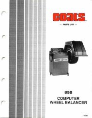
Parts IdentificationPARTITEM NO. QTY. DESCRIPTION1 110936 1 Chassis2 143862 1 Pad, Anti-Skid3 308860 1 Cover, Hand Hole4 106301 10 Screw, 1/4 x 3/4 HH Self-Tap5 106303 6 Nut, 3/8 Whiz Lock6 111036 3 Piezo Assembly7 301017 3 Ball, Steel, 1/2” Dia., Piezo8 307022 2 Bracket, Capacitor110558 1 Bracket Capacitor9 111815 1 Capacitor Assembly, 1P 110V111814 1 Capacitor Assembly, 1P 220V10 112208 4 Standoff, 8-32 male, 3/8 high11 301094 2 Screw, 8-32 x 3/4 Flat Head12 301084 4 Nut, #8-32 Kep14 106302 10 Screw, 3/8 Whiz Lock15 111218 1 Breaker, 2 Amp16 301067 12 Screw, #6-32 Phillips PHM,Patch Lock17 305802 1 Switch, On-Off18 110897 1 Power Panel19 106304 2 Skin Fastener, Tinnerman20 111793 1 PCB Assembly21 110579 1 Touch Panel22 308878 1 Weight Tray23 308017 1 Button, Rubber, Black25 306806 1 Transformer26 111542 6 Screw, #8-32 x 1/2 PhillipsPan Head27 111879 1 Motor Control Board28 143956 2 Retainer, Bushing29 110168 1 Stop, Distance Gauge30 308023 1 Spring, Distance Gauge31 107635 2 Washer, 3/8” Flat32 301142 1 Washer, Lock33 104755 4 Nut, Tinnerman34 110543 1 Hub Nut35 110542 1 Pressure Drum, Small36 308105 1 Ring, No-Mar37 110410 1 Cone, Small38 110411 1 Cone, Medium39 110412 1 Cone, Large40 308820 1 Spring, Cone Back41 308171 1 Stub Shaft42 110671-4 1 Motor, 110V110671-5 1 Motor, 220VPARTITEM NO. QTY. DESCRIPTION43 143847 1 Plug, 3/444 308817 1 Shutter, Encoder45 110902 1 Encoder Assembly46 308859 1 Cover, Encoder47 301072 3 Washer, Lock #648 301063 3 Screw, 6-32 x 1/249 301016 1 Bolt, Shoulder, ¯3/8 x 3/8 Lg.50 301035 4 Nut, 3/8-16 Nyloc51 308036 4 Ret, Piezo Spring52 30<strong>700</strong>8 4 Spring, Piezo53 111074 1 Cradle, Motor54 120325 2 Screw, 5/16-18 x 1 Whiz Lock55 301121 4 Washer, 1/256 308808 1 Flex Plate57 301033 4 Nut 3/8-16 Jam58 108727 4 Stud, 3/8-16 x 6.7560 143845 1 Gasket, motor61 111645 1 Scale, Distance Gauge62 143808 1 Assembly, Distance Gauge63 111818 1 Harness, Power Panel64 110903 1 Harness, Piezo65 111066-5 1 Wire Assembly, 22 AWGBrown66 111802 1 Wire Assembly Switch to M/CBoard67 111803 1 Wire Assembly Transformer toM/C Board68 111805-1 1 Wire Assembly PCB to M/CBoard69 111819 1 Wire Assembly InterlockSwitch70 143796 1 Power Cord, 110V Plug143796-2 1 Power Cord, 1P 220V71 6058 1 Strain Relief72 308550 1 Arm, Distance Gauge74 308535 1 Spacer75 308074 2 Bushing, Rear76 104200 1 Washer, Int. Lock 3/8 ID77 111136 2 Screw, 1/4 x 1/2 HH Self Tap8 • COATS <strong>700</strong> <strong>Balancer</strong>
Model <strong>700</strong> <strong>Balancer</strong> Parts Identification DiagramCOATS <strong>700</strong> <strong>Balancer</strong> • 9
111807 3/00 rev. 1 ©Copyright 1999 Hennessy Industries and COATS All Rights Reserved Printed in U.S.A.