PH4005 POWER CRIMP TOOL - Daniels Manufacturing Corporation
PH4005 POWER CRIMP TOOL - Daniels Manufacturing Corporation
PH4005 POWER CRIMP TOOL - Daniels Manufacturing Corporation
- No tags were found...

Create successful ePaper yourself
Turn your PDF publications into a flip-book with our unique Google optimized e-Paper software.
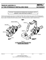
<strong>PH4005</strong><strong>POWER</strong> <strong>CRIMP</strong> <strong>TOOL</strong>SAFETY OPERATION MANUALINTRODUCTIONThe <strong>PH4005</strong> Power Crimp Tool is a pneumatic/hydraulic powered version of the DMC HX4 (M22520/5-01) hand crimptool, and uses the same interchangeable dies*. The basic system consists of a hand tool (PH4ST) and the PHRPU4Remote Power Unit. These tools are very powerful requiring 80-120 psi (5.5-8.3 BAR) air pressure to operatewhile producing a force of up to 4,000 pounds in the crimp area which can cut off or crush fingers andother body parts if inserted into the "crimp area" of the tool. The PH4ST Power Crimp Tool uses theM22520/5 (DMC “Y”)* dies which contain multiple and larger crimp cavities.*NOTE: Dies for PH4ST tool must be ordered separately. Please contact one of our customer servicerepresentatives for ordering information.IMPORTANT SAFETY INSTRUCTIONS / USER’S RESPONSIBILITIESWhen connected together, the PH4ST, along with the Remote Power Unit, constitute an integrated operating system.Under no circumstances should the crimping tool be attached to any control box or power system other than thecontrol unit provided (PHRPU4). It is imperative that operators using this tool system follow the noted safetyprecautions, be alert at all times and observe the highest level of operator safety.1. Disconnect from air supply when tool is not in use or when changing dies.2. Keep all body parts clear of the crimping area while loading and operating the tool.3. Restrict operation of the <strong>PH4005</strong> system to a single operator and follow the directions on the warning label.4. Do not alter the tool or operate outside the guidelines specified in this data sheet.It is the user’s responsibility to properly train and instruct all tool operators in the proper use of this tool.The operator must be made aware of the danger of the moving parts, the possibility of serious injury tofingers and other body parts if inserted into the crimp area; and the need to be alert and attentive at alltimes while using this tool.PREPARING <strong>TOOL</strong> FOR OPERATION (see Figure 1)The <strong>PH4005</strong> Power Crimp Tool consists of the PH4ST Crimp Tool, PHRPU4 Remote Power Unit, PHFV-3 FootPress (optional), and the BM-2 Bench Mount (optional). Four features used for operation or control can be seen onthe front panel of the PHRPU4 Remote Power Unit, they include the Hydraulic Quick Disconnect, Dual CouplingControl, Single Coupling Control, and the Input Air Quick Disconnect. Use the following steps to assemble theseparate parts:1. Connect the hydraulic hose from the PH4ST Crimp Tool into the hydraulic quick disconnect on the front panelof the PHRPU4 Remote Power Unit by pushing back on the locking ring of the hydraulic quick disconnect andplugging the male part of the hydraulic hose into the provided area. The operator will realize the connection hasbeen made when the locking ring snaps into place.2. Connect the small tool control hose from the PH4ST Crimp Tool to the single coupling control on the frontpanel of the PHRPU4 Remote Power Unit by pushing the connecting end of hose into the fitting until the springclip locks into place.3. Connect the shop air supply to the air quick disconnect by pulling back on the air hose coupling and inserting thehose into the fitting on the PHRPU4 Remote Power Unit.4. If PHFV-3 Foot Press is supplied, connect it to the dual coupling control by orienting the connector on the hoseso the side marked "TOP" is up, then press inward until the spring clips lock into place.DANIELS MANUFACTURING CORP., 526 THORPE ROAD, ORLANDO, FL 32824, USAPHONE (407) 855-6161 • FAX (407) 855-6884 • WWW.DMC<strong>TOOL</strong>S.COM • E-MAIL: DMC@DMC<strong>TOOL</strong>S.COMCOPYRIGHT© 2001ALL RIGHTS RESERVED1of7REV. B 08/01 FILE #: SOM0002 DOC. #: <strong>PH4005</strong>-SOM
SAFETY OPERATION MANUAL5. If the BM-2 Bench Mount is supplied, attach it to the PH4ST Crimp Tool by threading the male thread of thebench mount into the female thread on the tool. Adjust tool to appropriate working position, and lock handle onbench mount.DUAL COUPLING CONTROLPHRPU4PH4STAIR BLEED(ACTUATOR)PHFV-3(OPTIONAL)HYDRAULIC QUICKDISCONNECTBM-2(OPTIONAL)EMERGENCY STOPINPUT AIRQUICK DISCONNECTSINGLE COUPLING CONTROLFIGURE 1EMERGENCY STOP BUTTONThe PHRPU4 Remote Power Unit is configured with an Emergency Stop Button. By pressing this button at any timeduring the crimp cycle, the forward motion on the crimp tool will stop and retract to the open position. Furtheroperation of the system will be inhibited until this Emergency Stop Button is rotated in a clockwise direction andallowed to release.OTHER <strong>TOOL</strong> PREPARATION REQUIREMENTS:Die Installation (see Figure 2):The dies are captured using a self contained retainer spring in the stationary and movable die holders. Use thefollowing steps to install the dies:1. Disconnect the PHRPU4 Remote Power Unit from the air supply.2. Remove die opener from the movable die holder.3. Align die rail slots in the die halves with the die rail in the crimp tool and push shank of the dies into holes. Itwill be necessary to push the spring loaded die holder to the rear to fully seat the movable die.4. Replace the die opener mechanism in the movable die holder.5. Reconnect the air supply and activate the tool to assure that dies are properly seated.DISCONNECT FROMAIR SUPPLYBEFORE ATTEMPTINGTO ADJUST<strong>TOOL</strong> OR DIES.DANIELS MANUFACTURING CORP., 526 THORPE ROAD, ORLANDO, FL 32824, USAPHONE (407) 855-6161 • FAX (407) 855-6884 • WWW.DMC<strong>TOOL</strong>S.COM • E-MAIL: DMC@DMC<strong>TOOL</strong>S.COMCOPYRIGHT© 2001ALL RIGHTS RESERVED2of7REV. B 08/01 FILE #: SOM0002 DOC. #: <strong>PH4005</strong>-SOM
SAFETY OPERATION MANUALPH4ST <strong>CRIMP</strong> <strong>TOOL</strong>HYDRAULIC FLUID FILL HOLEHEAD POSITIONINGHOLDING SCREWPUSH RODDIE RAIL<strong>TOOL</strong> BODYROTATABLE <strong>CRIMP</strong>ING HEADFIGURE 2Die Removal (see Figure 3):Use the following steps to remove the dies:1. Disconnect the tool from the air supply.2. Remove the die opener mechanism from the movable die holder.3. Place the die removal tool against the end of the die in the front die holder and tap gently. The die will releasefrom the holder and can now be removed by hand.4. Slide the die removal tool between the tool and the die body. Tilt the die removal tool upward in order to releasethe die which can now be removed by hand.TAP WITH HAMMERDIE REMOVAL <strong>TOOL</strong>DIE REMOVAL <strong>TOOL</strong>(HX3-82)FIGURE 3Permanent die assembly (see Figure 4):Use the following steps to permanently assemble the dies:1. Disconnect the tool from the air supply.2. Install dies in crimping tool.3. Drive longer lock pin (supplied with dies) through the hole in the forward tool body for the stationary die.4. Rotate the push rod until the holes in both the push rod and the movable die align. Drive shorter lock pin(supplied with dies) through the aligned holes until flush with or below die holder surface (or replace with thedie opener mechanism).5. Reconnect the air supply.DANIELS MANUFACTURING CORP., 526 THORPE ROAD, ORLANDO, FL 32824, USAPHONE (407) 855-6161 • FAX (407) 855-6884 • WWW.DMC<strong>TOOL</strong>S.COM • E-MAIL: DMC@DMC<strong>TOOL</strong>S.COMCOPYRIGHT© 2001ALL RIGHTS RESERVED3of7REV. B 08/01 FILE #: SOM0002 DOC. #: <strong>PH4005</strong>-SOM
SAFETY OPERATION MANUALHYDRAULIC FLUID FILL HOLEHEAD POSITIONINGHOLDING SCREWDIE OPENERAIR BLEED (ACTUATOR)FIGURE 4Tool Head Positioning (see Figure 4):The tool head on the PH4ST Crimp Tool may be rotated to any selectable position relative to the actuator that anoperator might prefer. To select or change the head position, loosen the head position holding screw so the head canbe turned by hand and rotate head to selected position, then tighten screw.Die Opener for PH4ST (see Figure 4):A die opener is included with the PH4ST Crimp Tool. This die opener can be used to open the movable die for easein installation of components for crimping. To use the die opener, a die set must be installed in the tool. The headposition holding screw must be loosened in order to rotate the head and achieve the proper alignment between theslot in the body with the hole through the push rod that is used for pinning dies in place. Remove lock pin if in placeand push the threaded end of the die opener through the hole in the push rod/die from either side. Screw the otherend of the die opener until snug. The head may now be rotated to preferred position for operator use. Tighten thehead positioning holding screw.<strong>TOOL</strong> OPERATION:After the <strong>PH4005</strong> tool has been assembled and the dies installed in their proper location, the system is ready foroperation. Use the following steps to operate the tool properly and safely:1. Connect the PHRPU4 Remote Power Unit to a standard shop air supply of 80-120 psi. (5.5-8.3 BAR).2. Insert component to be crimped in die set and properly position. The movable die is spring loaded and will holddie closed against part.3. Cover the air bleed (actuator) of the tool and start the crimp cycle (see Figure 4).4. If the PHFV-3 Foot Press is used, a momentary press of the pedal will start the crimp cycle.NOTE:Should the tool not complete its cycle and open, check the supply air pressure. If the pressure readsbelow 80 psi (5.5 BAR), bring it back up to a minimum of 80 psi (5.5 BAR). If the pressure isadequate, push the Emergency Stop Button on the top of the PHRPU4 Remote Power Unit in orderto open the tool. It will be necessary to check fluid level as indicated in the next section. Do not usethe tool for crimping until this default condition has been corrected.DANIELS MANUFACTURING CORP., 526 THORPE ROAD, ORLANDO, FL 32824, USAPHONE (407) 855-6161 • FAX (407) 855-6884 • WWW.DMC<strong>TOOL</strong>S.COM • E-MAIL: DMC@DMC<strong>TOOL</strong>S.COMCOPYRIGHT© 2001ALL RIGHTS RESERVED4of7REV. B 08/01 FILE #: SOM0002 DOC. #: <strong>PH4005</strong>-SOM
SAFETY OPERATION MANUALHYDRAULIC FLUID REFILL:Use the following procedure to replace lost system hydraulic fluid:1. PHVG VACUUM GENERATOR METHOD (see Figure 5): The PHVG Vacuum Generator is used with thevarious PH series systems for the removal of any air that might be present in the hydraulic hose or in thePHRPU4 intensifier, and the replacement of any fluid loss from leakage or evaporation.PHRPU4 REMOTE <strong>POWER</strong> UNITPHVG CONNECTION(ADAPTOR)EMERGENCY STOPAIR SUPPLYPHVG HYDRAULICFILL BOWLTO PHFV-3 FOOT PRESSSINGLE COUPLING CONTROLFIGURE 5Procedure: It is necessary to use the vacuum generator with an amount of hydraulic fluid in the bottom of thefill bowl. Remove the two screws that hold on the cover of the bowl and pull it open. With the bowl sitting flat,fill the bowl with about 1/4" of ISO46AW hydraulic fluid. Reassemble cover, align holes and tighten down withthe two screws just removed.Recharging tools: Plug the male coupling of the tool hose into the female quick disconnect coupling on thePHVG Vacuum Generator by pulling lock ring back while pushing the male plug in place. The lock ring willsnap back in place when released and the male plug is seated. Making sure the fill bowl is level so oil in thebowl covers the input from the bottom of the bowl, plug in the air supply to the fitting provided on the rear of thevacuum generator. As a vacuum is formed, air bubbles will pull through the oil in the bowl and the fluid levelwill rise slightly. Continue to allow the vacuum generator to "run" until there are no noticeable bubbles flowingthrough the system, or the flow of bubbles is at minimum. Unplug the air supply slowly and watch as the levelof fluid in the bowl lowers. After waiting about five seconds, the tool hose can be disconnected from the system.Recharging the PHRPU4: It is necessary to plug the adaptor into the vacuum generator and into the PHRPU4Remote Power Unit. Holding the fill bowl level with the PHRPU4 sitting on its four feet, plug the air supplyinto the vacuum generator. Run the unit until there are no air bubbles or they are minimal, then slowly unplugthe air supply. When the oil level no longer lowers (about five seconds) the generator/adaptor may be uncoupledDANIELS MANUFACTURING CORP., 526 THORPE ROAD, ORLANDO, FL 32824, USAPHONE (407) 855-6161 • FAX (407) 855-6884 • WWW.DMC<strong>TOOL</strong>S.COM • E-MAIL: DMC@DMC<strong>TOOL</strong>S.COMCOPYRIGHT© 2001ALL RIGHTS RESERVED5of7REV. B 08/01 FILE #: SOM0002 DOC. #: <strong>PH4005</strong>-SOM
SAFETY OPERATION MANUALfrom the PHRPU4 Remote Power Unit and the tool hose reconnected. If a system default occurs whereby a toolcloses and will not open without activating the Emergency Stop Button and the air supply is 80-120 psi (5.5-8.3BAR), charge both the tool and the PHRPU4 to correct the fault. If recharging does not correct the defaultcondition and the air supply is proper, return the system to DMC for service. It is recommended that a periodicschedule be maintained for charging the system. If fluid, other than small amounts, are displaced duringthe system charging, the schedule should be changed to charge more frequently. If heavy leakage is noted anddaily charging is required, the tool/PHRPU4 system should be returned to DMC for seal replacement. It shouldbe noted that small amounts of fluid will be present at the coupling during the charging of the system or whentools are disconnected from the PHRPU4.OPERATIONAL CHARACTERISTICS:The <strong>PH4005</strong> Power Crimp Tool builds up substantial internal hydraulic pressures in attaining the resultant crimpforce. This may result in some leakage of hydraulic fluid past the seals in the tool. This does not mean the toolcannot be used. As long as the tool gage properly, it will provide an adequate crimp. Add hydraulic fluid as necessary.Where the fluid leakage has become unacceptable, contact the DMC factory for the proper procedure to returnthe tool for seal replacement.PH SERIES GAGING:Periodic gaging is suggested to monitor and assure that the proper level of force is being generated in the crimparea. Use the following steps to assure proper gaging:1. Remove die set.2. Using the PH102 side (.990/.995) of the DMC G709 Gage Block, insert it between forward tool body and themoveable push rod. Make sure all fingers are clear of the "crimping" area before activating the tool.3. Activate the tool by covering the tool actuator or foot press and hold in closed position.4. If the gage block can be turned or pulled out when the tool is closed, the tool should not be used. A proper levelof force has not been achieved.5. If the gage block cannot be turned by hand or pulled out, the tool is acceptable for use.SAFETY SIGNAGESafety signs are placed on the <strong>PH4005</strong> Power Crimp Tool to make you aware that this tool could seriously injure ormaim you if care is not used while operating it.These signs are intended as a constant reminder of the potential risk involved. These signs should never be removedand should be replaced as needed.Signs alone will not prevent accidents from occurring. Operators must be properly trained in the use of the equipmentand be aware of the risks involved. While using the tool, it is important to be alert and avoid distractions.DANIELS MANUFACTURING CORP., 526 THORPE ROAD, ORLANDO, FL 32824, USAPHONE (407) 855-6161 • FAX (407) 855-6884 • WWW.DMC<strong>TOOL</strong>S.COM • E-MAIL: DMC@DMC<strong>TOOL</strong>S.COMCOPYRIGHT© 2001ALL RIGHTS RESERVED6of7REV. B 08/01 FILE #: SOM0002 DOC. #: <strong>PH4005</strong>-SOM
SAFETY OPERATION MANUALFINGER FREE AREASEMERGENCY STOP<strong>PH4005</strong> SYSTEM COMPONENTS:DISCONNECT FROMAIR SUPPLYBEFORE ATTEMPTINGTO ADJUST<strong>TOOL</strong> OR DIES.<strong>POWER</strong> <strong>TOOL</strong> SYSTEM ACCESSORIES:PART NUMBERPH4STPHRPU4PHVGQTY111DESCRIPTION<strong>CRIMP</strong>ING <strong>TOOL</strong>REMOTE <strong>POWER</strong> UNITVACUUM GENERATORPART NUMBERBM-2PHFV-3G709DESCRIPTIONBENCH MOUNTFOOT PRESSGAGE BLOCK<strong>Daniels</strong> <strong>Manufacturing</strong> Corp. offers complete refurbishing and recalibration services.DMC specially engineers and manufactures complete tool kits to satisfy individual customer requirements, such astotal aircraft support, general shop maintenance or production, on board ship and vehicle service, etc.LIMITATION OF LIABILITY/LIMITED WARRANTY*DMC (DANIELS MANUFACTURING CORP.) IS NOT LIABLE FOR CONSEQUENTIALOR SPECIAL DAMAGES OF ANY NATURE OR KIND RESULTING FROM THE USE, OR MISUSE, OFANY OF ITS PRODUCTS. OWNERS AND USERS OF DMC PRODUCTS ASSUME FULL RESPONSI-BILITY FOR INSTRUCTING OPERATORS IN THE PROPER AND SAFE USE OF SUCH PRODUCTS.OPERATORS ASSUME FULL RESPONSIBILITY FOR OPERATING DMC PRODUCTS IN A SAFE MAN-NER AND ACCORDING TO DMC OPERATING INSTRUCTIONS.DMC (<strong>Daniels</strong> <strong>Manufacturing</strong> Corp.) warrants each new product sold by it to be free from defects inmaterial and workmanship under normal use and service. DMC's obligation under this warranty is limited to thefree correction or, at DMC's option, the refund of the purchase price of any such product which proves defectivein normal service within ninety (90) days after delivery to the first user, provided that the product is returned toDMC with all transportation charges prepaid and which shall appear to DMC's satisfaction, after DMC's inspection,to have been defective in material or workmanship, it being understood that DMC products are not consumerproducts. This warranty shall not cover any damage to any product which, in the opinion of DMC, wascaused by normal wear, misuse, improper operation, tampering, neglect or accident.This limited warranty is in lieu of all other warranties express or implied, including, but not limited to,warranties of fitness for a particular purpose and warranties of safe operation. No warranty, express or implied,is made or authorized to be made or assumed with respect to products of <strong>Daniels</strong> <strong>Manufacturing</strong> <strong>Corporation</strong>,other than that herein set forth.*as defined by PL93-637DANIELS MANUFACTURING CORP., 526 THORPE ROAD, ORLANDO, FL 32824, USAPHONE (407) 855-6161 • FAX (407) 855-6884 • WWW.DMC<strong>TOOL</strong>S.COM • E-MAIL: DMC@DMC<strong>TOOL</strong>S.COMCOPYRIGHT© 2001ALL RIGHTS RESERVED7of7REV. B 08/01 FILE #: SOM0002 DOC. #: <strong>PH4005</strong>-SOM