XLPE Land Cable Systems User´s Guide - Abb
XLPE Land Cable Systems User´s Guide - Abb
XLPE Land Cable Systems User´s Guide - Abb
- No tags were found...

Create successful ePaper yourself
Turn your PDF publications into a flip-book with our unique Google optimized e-Paper software.
CONTENT<strong>XLPE</strong> <strong>Land</strong> <strong>Cable</strong> <strong>Systems</strong>Introduction.................................................................... 3Design, installation and testing......................................... 4<strong>XLPE</strong> cables................................................................ 4<strong>Cable</strong> accessories....................................................... 4Installation of <strong>XLPE</strong> cable systems................................ 5Testing of <strong>XLPE</strong> cable systems..................................... 5<strong>XLPE</strong> cable and cable system standards.......................... 6IEC............................................................................. 6CENELEC ................................................................... 6ICEA........................................................................... 6ISO Standards............................................................. 6<strong>XLPE</strong> land cable system configurations............................ 7Trefoil and flat formation............................................... 7Bonding of metallic screens......................................... 7Current rating for <strong>XLPE</strong> land cable systems...................... 8Current rating for single-core cables............................. 9Rating factors.............................................................. 11Overload capacity........................................................ 12Short-circuit currents................................................... 12Dynamic forces during short circuit events.................... 13<strong>Cable</strong> drums - testing - cable handling............................. 14Selection of cable drum............................................... 14Testing of <strong>XLPE</strong> cables................................................. 15<strong>Cable</strong> handling............................................................ 15<strong>XLPE</strong> <strong>Cable</strong> Design......................................................... 16Conductors ................................................................ 16Insulation.................................................................... 17Metallic screen............................................................ 17Non-metallic outer sheath ........................................... 18Conductive outer layer ................................................ 18Flame retardant outer layer........................................... 18Fire behavior ............................................................... 18Technical data for <strong>XLPE</strong> land cable systems..................... 19Formulae........................................................................ 23Support.......................................................................... 24Checklist for <strong>Cable</strong> Inquiry............................................... 25To make sure you have the latest version of this brochure,have a look at www.abb.com/cables2 <strong>XLPE</strong> <strong>Land</strong> <strong>Cable</strong> <strong>Systems</strong> | ABB
INTRODUCTIONInterfaces you can trustABB manufactures land and submarine power cables up tothe highest voltages available.Furthermore, we produce associated joints, terminations andother accessories for all types of cables. The products aredesigned to work together as a cable system.Experience you can rely onWe have extensive experience of cable projects all over theworld, encompassing every aspect from planning to commissioning,including engineering, route surveys, cable-laying,installation and final testing. Very few manufacturers can pointto such a long tradition in the high voltage field as ABB. Wedelivered our first electrical cable in 1883 and introducedtriple-extruded <strong>XLPE</strong> cables around 1970. In the early 1970swe started to supply cables for over 100 kV and our first 245kV <strong>XLPE</strong> cable was put into service in 1978. ABB has sincethen supplied more than 8,800 km of <strong>XLPE</strong> cables above100 kV. Experience you can rely on.Research and developmentABB has always been a pioneer in the high voltage field andwe have many world’s first and world records among ourreferences. But there are no shortcuts to success. Maintainingour position calls for innovative research and development,backed up by the wealth of know-how we have accumulatedover the years. One of the driving forces for our R&D is tomeet the new and constantly increasing requirements fromthe power industry and a deregulated market. Today we aimto develop the solutions our customers will need tomorrow.State-of-the-art manufacturing linesExperience and state-of-the-art expertise go hand in hand forus. We have been manufacturing cables for over 125 yearsand have since the beginning been one of the leading producers.Our manufacturing plants are among the most modern inthe world and our advanced quality system leaves nothing tochance. Every cubic millimeter of the cable has to be perfect.We design and produce cables in accordance with internationaland national standards or/and according to our customers’specifications.This guide presents <strong>XLPE</strong> cables and systems for landapplications mainly.ABB | <strong>XLPE</strong> <strong>Land</strong> <strong>Cable</strong> <strong>Systems</strong> 3
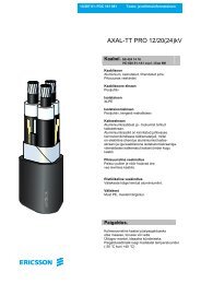
DESIGN, INSTALLATION AND TESTING<strong>XLPE</strong> cables<strong>XLPE</strong> cables consist of the following components:−−ConductorCopper (Cu) or Aluminium (Al) stranded compactedconductor orCu segmental conductor orCu or Al conductor with key-stone shaped profilesLongitudinal water sealing of conductor−−Triple extruded and dry cured <strong>XLPE</strong> insulation system−−Metallic screenCopper wire screenCopper tape screenRadial water sealingMetallic laminate solidly bonded to outerpolyethylene sheath orLead sheathLongitudinal water sealing of metallic screen−−Non-metallic outer sheathPEPVCHalogen free flame retardantCo-extruded conductive layer over the sheath forspecial sheath testing<strong>Cable</strong> accessoriesABB’s line-up of cable accessories for ABB <strong>XLPE</strong> cablesystems includes:−−Straight joints and joints with integrated screenseparation for cross bonding−−Transition joints for connection of <strong>XLPE</strong> to fluidfilledcables−−Outdoor terminations with porcelain or compositeinsulators−−Screened separable connectors for switchgears andtransformers−−<strong>Cable</strong> terminations for transformers andGas Insulated Switchgears (GIS)−−Link boxes for earthing and cross-bonding−−Distributed Temperature Sensing (DTS) <strong>Systems</strong> withintegrated optical fibre in metallic tube (FIMT)More information about our accessories is available onwww.abb.com4 <strong>XLPE</strong> <strong>Land</strong> <strong>Cable</strong> <strong>Systems</strong> | ABB
DESIGN, INSTALLATION AND TESTINGInstallation of <strong>XLPE</strong> cable systemsInstallation of cable systems includes trenching, cable pulling,clamping of cable, cable splicing as well as mountingof accessories. High quality installation work performed byABB certified field personnel is essential for achieving the lowfailure rates and reliability performance that is expected frommodern underground transmission and distribution circuits.ABB has long and extensive experience from different types ofcable installations including direct burial, duct, shaft, trough,tunnel and submarine installations, but also trenchless technologieslike directional drilling, pipe jacking and others.Testing of <strong>XLPE</strong> cable systemsStandard routine tests, sample tests, type tests and after layingtests are normally performed according to IEC-standards.Other international or national standards may be followedupon agreement between contractor and purchaser.Routine tests of <strong>XLPE</strong> cables and accessories−−PD measurement test−−High-voltage test of main insulation−−Electrical test of oversheath−−Visual inspectionSample testsSample tests are carried out with a frequency according toapplicable IEC standards.−−Conductor examination−−Electrical resistance of conductor−−Check of dimensions−−Capacitance test−−Hot set test−−Electrical testsAfter laying tests−−DC voltage test of oversheath−−AC voltage test of main insulationABB | <strong>XLPE</strong> <strong>Land</strong> <strong>Cable</strong> <strong>Systems</strong> 5
<strong>XLPE</strong> CABLE AND CABLE SYSTEM STANDARDSABB´s <strong>XLPE</strong> cable systems are designed to meet requirementsin international and/or national standards. Some ofthese are listed below.IEC<strong>XLPE</strong> cable systems specified according to IEC (InternationalElectrotechnical Commission) are among many other standardsaccepted. IEC standards are considered to express aninternational consensus of opinion.Some frequently used standards are:IEC 60228Conductors of insulated cables.IEC 60287Electric cables - Calculation of the current rating.IEC 60332Tests on electric cables under fire conditions.IEC 60502Power cables with extruded insulation and their accessoriesfor rated voltage from 1 kV (Um=1,2 kV) up to 30 kV (Um=36kV).IEC 60840Power cables with extruded insulation and their accessoriesfor rated voltage above 30 kV (Um=36 kV) up to 150 kV(Um=170 kV). Test methods and requirements.IEC 60853Calculation of the cyclic and emergency current rating ofcables.IEC 61443Short-circuit temperature limits of electric cables with ratedvoltages above 30 kV (Um=36 kV).IEC 62067Power cables with extruded insulation and their accessoriesfor rated voltage above 150 kV (Um=170 kV) up to 500 kV(Um=550 kV). Test methods and requirements.CENELECIn Europe, cable standards are issued by CENELEC. (EuropeanCommittee for Electrotechnical Standardization.) They areas a rule implementations of the IEC specifications. Specialfeatures in design may occur depending on national conditions.HD 620Distribution cables with extruded insulation for rated voltagesfrom 3.6/6 (7.2) kV up to and including 20.8/36 (42) kV.HD 632Power cables with extruded insulation and their accessoriesfor rated voltage above 36 kV (Um=42 kV) up to 150 kV(Um=170 kV). Part 1- General test requirements.Part 1 is based on IEC 60840, and follows that standardclosely.HD 632 is completed with a number of parts and subsectionsfor different cables intended to be used under special conditionswhich can vary nationally in Europe.ICEAFor North America cables are often specified according toICEA (Insulated <strong>Cable</strong> Engineers Association, Inc.).S-97-682Standard for utility shielded power cables rated 5-46 kV.S-108-720Standard for extruded insulated power cables rated above 46through 345 kV.ISO StandardsABB has well-developed systems for quality and environmentalmanagement which put the needs and wishes of thecustomer first. Our systems comply with the requirements ofISO 9001 and ISO 14001 and are certified by Bureau VeritasQuality International.ISO 14001 and ISO 9001Certificate of Approval6 <strong>XLPE</strong> <strong>Land</strong> <strong>Cable</strong> <strong>Systems</strong> | ABB
<strong>XLPE</strong> LAND CABLE SYSTEM CONFIGURATIONSTrefoil and flat formationThe three cables in a 3-phase circuit can be placed in differentformations. Typical formations include trefoil (triangular)and flat formations. The choice depends on several factorslike screen bonding method, conductor area and availablespace for installation.Trefoil or flat formationBonding of the metallic screensThe electric power losses in a cable circuit are dependenton the currents flowing in the metallic sheaths of the cables.Therefore, by reducing or eliminating the metallic sheathcurrents through different methods of bonding, it is possibleto incresase the load current carrying capacity (ampacity) ofthe cable circuit. The usual bonding methods are describedbelow:Both-ends bondingA system is both ends bonded if the arrangements are suchthat the cable sheaths provide path for circulating currents atnormal conditions. This will cause losses in the screen, whichreduce the cable current carrying capacity. These losses aresmaller for cables in trefoil formation than in flat formation withseparation.Single-point bondingA system is single point bonded if the arrangements are suchthat the cable sheaths provide no path for the flow of circulatingcurrents or external fault currents. In such case, a voltagewill be induced between screens of adjacent phases of thecable circuit and between screen and earth, but no currentwill flow. This induced voltage is proportional to the cablelength and current. Single-point bonding can only be used forlimited route lengths, but in general the accepted screen voltagepotential limits the length.Cross-bondingA system is cross-bonded if the arrangements are suchthat the circuit provides electrically continuous sheath runsfrom earthed termination to earthed termination but withthe sheaths so sectionalized and cross-connected in orderto eliminate the sheath circulating currents. In such case, avoltage will be induced between screen and earth, but nosignificant current will flow. The maximum induced voltagewill appear at the link boxes for cross-bonding. This methodpermits a cable current-carrying capacity as high as withsingle-point bonding but longer route lengths than the latter. Itrequires screen separation and additional link boxes.ABB | <strong>XLPE</strong> <strong>Land</strong> <strong>Cable</strong> <strong>Systems</strong> 7
CURRENT RATING FOR <strong>XLPE</strong> LAND CABLE SYSTEMSThe <strong>XLPE</strong> cable should at least have a conductor crosssection area adequate to meet the system requirements forpower transmission capacity. The cost of energy losses canbe reduced by using larger conductor.Load losses in <strong>XLPE</strong> cables are primarily due to the ohmiclosses in the conductor and the metallic screen. <strong>XLPE</strong> cables canbe loaded continuously to a conductor temperature of 90°C.The dielectric losses in the <strong>XLPE</strong> insulation system arepresent also at no load current and depend primarily on themagnitude of the operating voltage.Dielectric losses in <strong>XLPE</strong> cables are lower than for EPR andfluid-filled cables.Continuous current ratings for single-core cables are givenin tables 1-4. The continuous current ratings are calculatedaccording to IEC 60287 series of standards and with the followingconditions:−−One three-phase group ofsingle-core cables−−Ground temperature 20°C−−Ambient air temperature 35°C−−Laying depth L1.0 m−−Distance “s” between cableaxes laid in flat formation 70 mm + D e−−Ground thermal resistivity 1.0 Km/WRating factors for single-core cables are given in Tables 5-13.8 <strong>XLPE</strong> <strong>Land</strong> <strong>Cable</strong> <strong>Systems</strong> | ABB
CURRENT RATING FOR <strong>XLPE</strong> LAND CABLE SYSTEMSCurrent rating for single-core cables, ampèresTable 1CrosssectionconductorRated voltage 45-66 kV, aluminium conductor – 35 mm 2 screen<strong>Cable</strong>s in Ground<strong>Cable</strong>s in AirFlat formation Trefoil formation Flat formation Trefoil formationCross bonded Both ends Cross bonded Both ends Cross bonded Both ends Cross bonded Both endsmm 2 65 o C 90 o C 65 o C 90 o C 65 o C 90 o C 65 o C 90 o C 65 o C 90 o C 65 o C 90 o C 65 o C 90 o C 65 o C 90 o C95 220 265 215 260 210 250 210 250 230 310 225 305 200 270 200 270120 250 300 245 295 235 285 240 285 265 355 260 350 230 310 230 315150 280 335 270 325 265 320 265 320 305 410 290 395 260 355 260 355185 320 380 300 365 300 360 300 360 350 470 330 445 300 405 300 405240 370 445 345 420 350 420 350 420 410 555 380 520 355 480 350 480300 420 500 385 465 395 475 390 470 475 640 430 590 405 550 400 550400 480 575 430 520 455 545 445 540 555 745 490 675 470 645 465 635500 550 660 480 585 520 620 505 610 645 870 555 765 550 750 540 735630 630 755 530 650 590 710 570 690 750 1020 630 870 635 870 620 850800 710 855 580 710 665 805 640 775 870 1180 700 975 730 1005 705 9751000 795 960 625 775 740 895 700 855 995 1350 770 1080 830 1140 795 11001200 860 1040 660 815 795 965 750 915 1095 1490 820 1155 905 1245 855 11901400 920 1115 685 855 845 1030 790 965 1190 1620 870 1225 975 1345 915 12751600 970 1175 710 885 890 1080 820 1005 1265 1730 905 1285 1030 1425 965 13502000 1060 1285 745 930 960 1170 875 1075 1410 1930 965 1380 1135 1575 1050 1470Table 2CrosssectionconductorRated voltage 45-66 kV, copper conductor – 35 mm 2 screenSegmental conductor for 1200 mm 2 or higher<strong>Cable</strong>s in Ground<strong>Cable</strong>s in AirFlat formation Trefoil formation Flat formation Trefoil formationCross bonded Both ends Cross bonded Both ends Cross bonded Both ends Cross bonded Both endsmm 2 65 o C 90 o C 65 o C 90 o C 65 o C 90 o C 65 o C 90 o C 65 o C 90 o C 65 o C 90 o C 65 o C 90 o C 65 o C 90 o C95 285 340 275 330 270 320 270 325 295 400 285 390 255 350 255 350120 325 380 310 370 305 365 305 365 340 460 325 440 295 400 295 400150 360 435 340 410 345 410 340 410 390 525 360 495 335 455 335 455185 410 490 375 455 385 465 385 460 445 600 405 555 385 520 380 520240 475 570 425 515 450 540 440 530 525 710 465 640 450 615 445 610300 535 645 465 570 505 610 495 600 605 820 520 720 515 705 505 695400 610 735 515 630 575 690 560 675 705 955 585 815 595 815 580 800500 695 835 565 695 650 785 625 760 815 1105 655 910 690 945 665 915630 790 950 615 760 735 885 695 845 945 1285 725 1015 790 1085 755 1045800 885 1070 660 820 815 990 765 930 1080 1470 795 1120 895 1230 845 11751000 975 1180 700 870 890 1080 820 1005 1215 1660 855 1215 995 1375 930 12951200 1130 1365 755 945 1060 1280 930 1145 1450 1965 955 1360 1215 1670 1090 15201400 1220 1475 785 985 1140 1380 980 1210 1590 2160 1010 1440 1325 1825 1170 16401600 1300 1570 810 1015 1205 1465 1025 1265 1720 2340 1055 1510 1420 1960 1240 17402000 1425 1730 840 1060 1315 1600 1085 1345 1915 2620 1110 1595 1570 2175 1335 1885ABB | <strong>XLPE</strong> <strong>Land</strong> <strong>Cable</strong> <strong>Systems</strong> 9
CURRENT RATING FOR <strong>XLPE</strong> LAND CABLE SYSTEMSTable 3CrosssectionconductorRated voltage 110-500 kV, aluminium conductor – 95 mm 2 screen<strong>Cable</strong>s in Ground<strong>Cable</strong>s in AirFlat formation Trefoil formation Flat formation Trefoil formationCross bonded Both ends Cross bonded Both ends Cross bonded Both ends Cross bonded Both endsmm 2 65 o C 90 o C 65 o C 90 o C 65 o C 90 o C 65 o C 90 o C 65 o C 90 o C 65 o C 90 o C 65 o C 90 o C 65 o C 90 o C300 415 495 365 445 395 475 385 460 465 625 415 565 410 550 400 540400 470 565 410 500 450 540 435 525 535 715 470 640 475 640 460 625500 540 645 455 555 515 620 490 595 620 835 530 725 550 745 530 720630 620 740 500 610 590 710 550 670 730 975 595 820 640 865 605 830800 700 845 540 665 670 805 610 745 840 1130 660 910 735 995 685 9401000 785 950 585 720 745 900 670 820 960 1295 720 1005 830 1135 765 10551200 850 1025 610 755 805 970 710 870 1055 1420 765 1070 905 1235 825 11401400 910 1100 635 785 855 1040 745 915 1140 1545 805 1125 975 1335 880 12201600 960 1165 655 815 900 1095 775 955 1220 1650 835 1170 1035 1420 925 12852000 1050 1275 685 855 975 1190 820 1015 1355 1840 885 1250 1140 1570 1000 1395Table 4CrosssectionconductorRated voltage 110-500 kV, copper conductor – 95 mm 2 screenSegmental conductor for 1200 mm 2 or higher<strong>Cable</strong>s in Ground<strong>Cable</strong>s in AirFlat formation Trefoil formation Flat formation Trefoil formationCross bonded Both ends Cross bonded Both ends Cross bonded Both ends Cross bonded Both endsmm 2 65 o C 90 o C 65 o C 90 o C 65 o C 90 o C 65 o C 90 o C 65 o C 90 o C 65 o C 90 o C 65 o C 90 o C 65 o C 90 o C300 530 640 440 535 505 610 480 580 600 805 500 685 525 710 500 685400 600 720 485 595 575 690 540 650 680 915 565 775 605 820 575 785500 685 825 530 650 655 785 600 730 790 1060 625 860 695 945 650 895630 780 940 570 705 740 890 660 810 915 1235 685 950 800 1085 735 1010800 870 1055 610 755 825 995 720 885 1045 1415 745 1040 905 1235 815 11301000 960 1165 645 800 900 1095 770 950 1175 1590 800 1125 1005 1380 895 12451200 1115 1345 690 860 1060 1280 855 1055 1395 1880 880 1240 1210 1650 1025 14251400 1205 1455 715 890 1145 1385 895 1110 1530 2065 920 1300 1320 1800 1090 15251600 1280 1550 735 920 1215 1470 930 1155 1655 2235 960 1355 1420 1940 1150 16152000 1410 1705 765 955 1320 1605 980 1220 1845 2500 1000 1425 1565 2145 1230 17402500 1540 1875 795 1000 1445 1755 1025 1285 2095 2845 1065 1515 1750 2410 1330 189010 <strong>XLPE</strong> <strong>Land</strong> <strong>Cable</strong> <strong>Systems</strong> | ABB
CURRENT RATING FOR <strong>XLPE</strong> LAND CABLE SYSTEMSMaximum short circuit currents due to thermal restrictionsThe thermal energy developed during a short-circuit is determinedby the short-circuit magnitude and duration. For designpurposes, an equivalent short-circuit current with a durationof 1 sec is used according to formula below. This formula isvalid for a short-circuit duration of 0.2 to 5.0 sec.I sh= short-circuit current [kA] during time t shI 1= short-circuit current rating during 1 second. See the 1second value in Table 14 for the conductor and in Table 15 forthe metal screen.t sh= short-circuit duration (sec)For <strong>XLPE</strong> insulated conductors the maximum allowable shortcircuit temperature is 250 o C.Table 14Max. short-circuit current on the conductor during 1 s, kACrosssectionConductor temperature before the short-circuitAluminiumconductorCopperconductormm 2 65 o C 90 o C 65 o C 90 o C35 3.6 3.3 5.5 5.050 5.2 4.7 7.8 7.270 7.2 6.6 11.0 10.095 9.8 9.0 14.9 13.6120 12.4 11.3 18.8 17.2150 15.5 14.2 23.5 21.5185 19.2 17.5 29.0 26.5240 24.8 22.7 37.6 34.5300 31.1 28.3 47.0 42.9400 41.4 37.8 62.7 57.2500 51.8 47.2 78.4 71.5630 65.2 59.5 98.7 90.1800 82.8 75.6 125 1141000 104 94.5 157 1431200 124 113 188 1721400 145 132 219 2001600 166 151 251 2292000 207 189 313 286per mm 2 0.104 0.0945 0.157 0.143Copper screens may reach a temperature of 250 o C withoutdamaging adjacent insulating material. With an initial temperatureof 50 o C this corresponds to a current density of 165 A/mm 2 during 1s (both higher and lower current densities maybe allowed if other conditions apply).Lead sheath temperatures of up to 210 o C are permitted inconnection with short circuit events. With an initial temperatureof 50 o C this corresponds to a current density of28 A/mm 2 during 1 s.Table 15Max. short-circuit current on the screen during 1 s, kAMetallic screencross section, mm 2Metallic screen temperaturebefore the short-circuitCopper screen Lead sheath 50 o C 70 o C35 206 5.8 5.450 295 8.3 7.795 560 16 15150 884 25 23300 1768 50 46per mm 2 Cu 0.165 0.153per mm 2 Pb 0.028 0.026Dynamic forces during short circuit eventsIn addition to the thermal stresses, the dynamic forces in thecables and accessories during a short circuit event must alsobe considered.The dynamic effect of parallel conductors carrying current isresponsible for the dynamic force.The dynamic force between two conductors, can be calculatedas:Where; I peak= 2.5 I sh[kA]I shSF= Short-circuit current [kA] RMS= Centre to centre spacing betweenconductors [m]= Maximum force [N/m]ABB | <strong>XLPE</strong> <strong>Land</strong> <strong>Cable</strong> <strong>Systems</strong> 13
CABLE DRUMS - TESTING - CABLE HANDLINGSizes and weights of wooden drums and steel drumsTable 17Wooden drums - drum typeK16 K18 K20 K22 K24 K26 K28 K30 K321-20 K321-22Shipping volume m 3 2.86 3.58 5.12 6.15 7.36 10.56 13.88 17.15 23.55 23.55Drumweight incl. battens kg 275 320 485 565 625 1145 1460 1820 2000 2000a Diameter incl. battens mm 1675 1875 2075 2275 2475 2676 2876 3076 3276 3276b Flange diameter mm 1600 1800 2000 2200 2400 2600 2800 3000 3200 3200c Barrel diameter mm 950 1100 1300 1400 1400 1500 1500 1500 2000 2200d Total width mm 1018 1075 1188 1188 1200 1448 1650 1800 2300 2300e Spindle hole diameter mm 106 131 131 131 131 132 132 132 132 132Max. load kg 2500 3000 3500 4500 5000 10000 12000 13000 13000 13000Steel drums - drum typeSt 30 St 32 St 34 St 35 St 36 St 37 St 38 St 39 St 40Shipping volume m 3 23.5 26.6 28.9 31.6 33.4 35.2 37 38.9 40.9Drumweight incl. battens kg 1700 2200 2600 2700 2800 3000 3100 3300 3500a Diameter incl. battens mm 3130 3330 3530 3630 3730 3830 3930 4030 4130b Flange diameter mm 3000 3200 3400 3500 3600 3700 3800 3900 4000c Barrel diameter* mm 2000 2000 2000 2000 2200 2400 2500 2600 2700d Total width mm 2400 2400 2400 2400 2400 2400 2400 2400 2400e Spindle hole diameter mm 150 150 150 150 150 150 150 150 150Max. load kg 24000 24000 24000 24000 24000 24000 24000 24000 24000* May vary depending on cable designLarge and special drumsSteel drums with larger outer diameters are available, buttransport restrictions have to be considered. Special lowloadingtrailers and permits from traffic authorities might beneeded depending on local regulations and conditions.Special wooden drums with larger barrel diameter or largerwidth are also available.Testing of <strong>XLPE</strong> cablesTable 18Rated voltage and corresponding test voltages according to IECType testRoutine testsNominalvoltageImpulsevoltageAC voltagetestPartialdischargetest atkV kV kVDurationminuteskV45 250 65 30 3966 325 90 30 54110 550 160 30 96132 650 190 30 114150 750 218 30 131220 1050 318 30 190275 1050 400 30 240330 1175 420 60 285400 1425 440 60 330500 1550 580 60 435Tests according to other standards can be carried out upon agreement.<strong>Cable</strong> handlingMinimum bending radiusTable 19Minimum bending radius for single core cablesStd cable design* Special cable design**At laying 15 D e18 D eWhen installed 10 D e12 D eD eis the external diameter of the cablea Diameter incl. battensb Flange diameterc Barrel diameterd Total widthe Spindle hole diameter* Cu-wire screen only** Metallic laminated or lead sheathed cables or cables with integrated optic fibersMaximum pulling forcesThe following pulling forces should not be exceeded:Aluminium conductors 40 N/mm 2 (4 kg/mm 2 )Copper conductors 70 N/mm 2 (7 kg/mm 2 )Maximum side wall pressure (SWP)The following SWPs should not be exceeded:Buried installation (rollers placed close) 500 kg /m*Duct installation750 kg/m*FR* Depending on cable design and installation conditionshigher values may be accepted.ABB | <strong>XLPE</strong> <strong>Land</strong> <strong>Cable</strong> <strong>Systems</strong> 15
<strong>XLPE</strong> CABLE DESIGNConductorsTable 20Cross sectionIECDiameterapprox.Maximum d.c. resistanceat 20 o C, ohm/kmmm 2 kcmil mm aluminium copper95 187 11.2 0.320 0.193120 237 12.8 0.253 0.153150 296 14.2 0.206 0.124185 365 15.9 0.164 0.0991240 474 18.0 0.125 0.0754300 592 20.5 0.100 0.0601400 789 23.1 0.0778 0.0470500 987 26.4 0.0605 0.0366630 1243 30.2 0.0469 0.0283800 1579 33.9 0.0367 0.02211000 1973 37.9 0.0291 0.01761200 2368 44* 0.0247 0.01511600 3158 52* 0.0186 0.01132000 3944 56* 0.0149 0.00902500 4931 66* 0.0120 0.0072* Segmented Cu conductor including tapesTable 21Cross sectionICEADiameterapprox.Nominal d.c. resistanceat 20 o C, ohm/km **AWG kcmil mm 2 mm aluminium copper3/0 85 10.7 0.383 0.2064/0 107 12.1 0.269 0.164250 127 13.2 0.228 0.139300 152 14.5 0.190 0.116350 177 15.6 0.162 0.0990500 253 18.7 0.114 0.0695750 380 23.0 0.0759 0.04621000 507 26.9 0.0563 0.03471250 633 30.2 0.0454 0.02781500 760 33.5 0.0380 0.02311750 887 36.2 0.0325 0.01982000 1013 38.0 0.0285 0.01732500 1267 45* 0.0230 0.01403000 1520 48* 0.0189 0.01173500 1773 52.5* 0.0164 0.01004000 2027 55* 0.0143 0.00871 ohm/100 ft = 3.28 ohm/km* Segmented Cu conductor including tapes** The maximum value can be 2% higherStandards – IEC and ICEAConductors are manufactured according to the followingstandards:IEC (International Electrotechnical Commission) StandardPublication 60228, Class 2: Stranded circular or shaped conductorsof copper or aluminium.Conductor water sealingIf required, the conductor can be water sealed by:−−Swelling material between the conductor strands.This material turns into jelly when in contact with water.−−Filling compound between the conductor strands.ICEA, Standard Publication No. S-97-682, further specified inASTM B 400-18 for aluminium, ASTM B 496-81 for copper.16 <strong>XLPE</strong> <strong>Land</strong> <strong>Cable</strong> <strong>Systems</strong> | ABB
<strong>XLPE</strong> CABLE DESIGNInsulationConductor screenThe conductor screen consists of an extruded layer firmlybonded to the <strong>XLPE</strong> insulation. A very smooth material isused to obtain good electrical performance.<strong>XLPE</strong> insulationThe <strong>XLPE</strong> insulation is extruded simultaneously with the conductorscreen and the insulation screen, e.g. triple extrusion.The interface surfaces between insulation and conductivescreens are not exposed at any stage of the manufacturing.High quality material-handling systems, triple extrusion, drycuring and super-clean <strong>XLPE</strong> materials guarantee high qualityproducts. The insulation thickness is determined by thedesign electrical stresses for AC or impulse. The actual thicknessfor different voltage levels and conductor sizes is givenin Tables 22 to 32.Insulation screenThis screen consists of an extruded layer firmly bonded tothe <strong>XLPE</strong> insulation. The material is a high quality conductivecompound. The interface between the screen and the insulationis smooth.Metallic screenCopper wire screen, standard designA polymeric sheath covers the copper wire screen.Copper wire screen, water tight designRadial water sealing is achieved by using a metal-PE laminate.The metal is normally aluminium. Copper may also be used.The laminate is bonded to the polyethylene, which givesexcellent mechanical properties. Longitudinal water sealingis achieved by using a water swelling material at the copperwires or swelling powder between the screen wires.Lead sheathRadial water sealing achieved by a corrosion resistant leadsheath. Longitudinal water sealing is achieved by using a waterswelling material applied under the lead sheath.Copper tape screenCross section defined by the geometrical cross section of thecopper tapes.ABB | <strong>XLPE</strong> <strong>Land</strong> <strong>Cable</strong> <strong>Systems</strong> 17
TECHNICAL DATA FOR <strong>XLPE</strong> LAND CABLE SYSTEMSCrosssectionof conductorInsulationthicknessDiameteroverinsulationDiameterof conductorCrosssectionofscreenOuterdiameterof cable<strong>Cable</strong>weight(Al-conductor)<strong>Cable</strong>weight(Cu-conductor)CapacitanceChargingcurrentper phaseat 50 HzInductancemm 2 mm mm mm mm 2 mm kg/m kg/m µF/km A/km mH/km mH/km ΩSurgeimpedanceTable 22Single-core cables, nominal voltage 45 kV (U m= 52 kV)95 11.2 8.0 29.6 25 40.0 1.4 2.0 0.18 1.5 0.44 0.69 35.6120 12.6 8.0 31.0 25 41.6 1.5 2.3 0.19 1.6 0.43 0.67 33.2150 14.2 8.0 32.6 35 44.0 1.8 2.7 0.21 1.7 0.41 0.65 31.0185 15.8 8.0 34.2 35 45.6 1.9 3.1 0.22 1.8 0.40 0.63 28.9240 18.1 8.0 36.5 35 48.1 2.2 3.7 0.24 2.0 0.38 0.61 26.4300 20.4 8.0 38.8 35 50.6 2.5 4.3 0.26 2.1 0.37 0.59 24.4400 23.2 8.0 41.6 35 53.6 2.9 5.3 0.29 2.3 0.36 0.57 22.3500 26.2 8.0 45.0 35 57.2 3.3 6.4 0.32 2.6 0.34 0.55 20.4630 29.8 8.0 48.6 35 61.0 3.8 7.7 0.35 2.8 0.33 0.53 18.5800 33.7 8.0 52.5 35 65.7 4.5 9.5 0.38 3.1 0.32 0.51 17.01000 37.9 8.0 57.3 35 70.9 5.3 11.6 0.42 3.5 0.31 0.50 15.51200 42.8 8.0 63.8 35 77.8 6.3 13.8 0.48 3.9 0.31 0.48 14.21400 46.4 8.0 67.4 35 81.6 7.0 15.8 0.51 4.2 0.30 0.47 13.41600 49.8 8.0 70.8 35 85.2 7.8 17.7 0.54 4.4 0.30 0.46 12.62000 54.4 8.0 75.4 35 90.6 9.2 21.6 0.58 4.8 0.29 0.45 11.8Table 23Single-core cables, nominal voltage 66 kV (U m= 72.5 kV)95 11.2 9.0 31.6 25 42.2 1.5 2.1 0.16 2.0 0.45 0.70 38.0120 12.6 9.0 33.0 25 43.8 1.7 2.4 0.18 2.1 0.44 0.68 35.5150 14.2 9.0 34.6 35 46.0 1.9 2.8 0.19 2.3 0.42 0.65 33.1185 15.8 9.0 36.2 35 47.8 2.1 3.2 0.20 2.4 0.41 0.64 31.0240 18.1 9.0 38.5 35 50.3 2.3 3.8 0.22 2.6 0.39 0.61 28.4300 20.4 9.0 40.8 35 52.8 2.6 4.5 0.24 2.9 0.38 0.59 26.2400 23.2 9.0 43.6 35 55.8 3.0 5.5 0.26 3.1 0.36 0.57 24.0500 26.2 9.0 47.0 35 59.4 3.5 6.6 0.29 3.4 0.35 0.55 22.0630 29.8 9.0 50.6 35 63.2 4.0 7.9 0.32 3.8 0.34 0.53 20.0800 33.7 9.0 54.5 35 67.9 4.7 9.7 0.35 4.1 0.33 0.52 18.41000 37.9 9.0 59.3 35 72.9 5.5 11.8 0.38 4.6 0.32 0.50 16.81200 42.8 9.0 65.8 35 79.8 6.5 14.0 0.43 5.2 0.31 0.49 15.41400 46.4 9.0 69.4 35 83.8 7.3 16.0 0.46 5.5 0.31 0.47 14.51600 49.8 9.0 72.8 35 87.4 8.0 18.0 0.49 5.9 0.30 0.47 13.72000 54.4 9.0 77.4 35 92.8 9.5 21.9 0.52 6.3 0.30 0.45 12.8ABB | <strong>XLPE</strong> <strong>Land</strong> <strong>Cable</strong> <strong>Systems</strong> 19
TECHNICAL DATA FOR <strong>XLPE</strong> LAND CABLE SYSTEMSCrosssectionof conductorInsulationthicknessDiameteroverinsulationDiameterof conductorCrosssectionofscreenOuterdiameterof cable<strong>Cable</strong>weight(Al-conductor)<strong>Cable</strong>weight(Cu-conductor)CapacitanceChargingcurrentper phaseat 50 HzInductancemm 2 mm mm mm mm 2 mm kg/m kg/m µF/km A/km mH/km mH/km ΩSurgeimpedanceTable 24Single-core cables, nominal voltage 70 kV (U m=84 kV)150 14.2 10.0 36.6 35 48.2 2.0 3.0 0.18 2.2 0.43 0.66 35.2185 15.8 10.0 38.2 35 50.0 2.2 3.4 0.19 2.4 0.42 0.64 33.0240 18.1 10.0 40.5 35 52.3 2.5 4.0 0.20 2.6 0.40 0.62 30.2300 20.4 10.0 42.8 35 54.8 2.8 4.6 0.22 2.8 0.39 0.60 28.0400 23.2 10.0 45.6 35 57.8 3.2 5.7 0.24 3.1 0.37 0.58 25.6500 26.2 10.0 49.0 35 61.4 3.6 6.7 0.26 3.4 0.36 0.56 23.5630 29.8 10.0 52.6 35 65.4 4.2 8.1 0.29 3.7 0.35 0.54 21.4800 33.7 10.0 56.5 35 69.9 4.9 9.9 0.32 4.0 0.33 0.52 19.71000 37.9 10.0 61.3 35 75.1 5.8 12.0 0.35 4.5 0.33 0.50 18.01200 42.8 10.0 67.8 35 82.0 6.8 14.3 0.40 5.0 0.32 0.49 16.51400 46.4 10.0 71.4 35 85.8 7.5 16.3 0.42 5.4 0.31 0.48 15.51600 49.8 10.0 74.8 35 90.0 8.4 18.3 0.45 5.7 0.31 0.47 14.82000 54.4 10.0 79.4 35 94.8 9.7 22.2 0.48 6.1 0.30 0.46 13.8Table 25Single-core cables, nominal voltage 110 kV (U m= 123 kV)185 15.8 16.0 50.2 95 63.3 3.7 4.9 0.14 2.7 0.47 0.66 43.0240 18.1 15.0 50.5 95 63.6 3.9 5.4 0.15 3.1 0.44 0.63 38.4300 20.4 14.0 50.8 95 63.9 4.0 5.9 0.17 3.5 0.42 0.61 34.3400 23.2 13.0 51.6 95 64.9 4.3 6.8 0.20 4.0 0.39 0.59 30.2500 26.2 13.0 55.0 95 68.5 4.8 7.9 0.22 4.3 0.38 0.57 27.8630 29.8 13.0 58.6 95 72.3 5.3 9.3 0.24 4.7 0.37 0.55 25.5800 33.7 13.0 62.5 95 76.8 6.1 11.1 0.26 5.2 0.35 0.53 23.51000 37.9 13.0 67.3 95 82.0 7.0 13.2 0.28 5.7 0.34 0.51 21.61200 42.8 13.0 73.8 95 89.5 8.2 15.6 0.32 6.4 0.34 0.50 19.81400 46.4 13.0 77.4 95 93.3 9.0 17.7 0.34 6.8 0.33 0.49 18.71600 49.8 13.0 80.8 95 96.9 9.7 19.7 0.36 7.1 0.32 0.48 17.72000 54.4 13.0 85.4 95 101.9 11.2 23.6 0.38 7.6 0.31 0.46 16.62500 62.0 13.0 93.0 95 109.9 13.1 28.7 0.42 8.5 0.30 0.45 14.920 <strong>XLPE</strong> <strong>Land</strong> <strong>Cable</strong> <strong>Systems</strong> | ABB
TECHNICAL DATA FOR <strong>XLPE</strong> LAND CABLE SYSTEMSCrosssectionof conductorInsulationthicknessDiameteroverinsulationDiameterof conductorCrosssectionofscreenOuterdiameterof cable<strong>Cable</strong>weight(Al-conductor)<strong>Cable</strong>weight(Cu-conductor)CapacitanceChargingcurrentper phaseat 50 HzInductancemm 2 mm mm mm mm 2 mm kg/m kg/m µF/km A/km mH/km mH/km ΩSurgeimpedanceTable 26Single-core cables, nominal voltage 132 kV (U m= 145 kV)185 15.8 18.0 54.2 95 67.5 4.1 5.3 0.13 3.0 0.48 0.67 45.8240 18.1 17.0 54.5 95 68.0 4.3 5.8 0.14 3.4 0.45 0.64 41.1300 20.4 16.0 54.8 95 68.3 4.4 6.3 0.16 3.8 0.43 0.62 37.1400 23.2 15.0 55.6 95 69.1 4.6 7.1 0.18 4.3 0.41 0.59 33.0500 26.2 15.0 59.0 95 72.7 5.2 8.3 0.20 4.7 0.39 0.57 30.4630 29.8 15.0 62.6 95 76.5 5.8 9.7 0.21 5.1 0.38 0.55 27.9800 33.7 15.0 66.5 95 81.2 6.6 11.5 0.23 5.5 0.36 0.54 25.81000 37.9 15.0 71.3 95 86.4 7.5 13.7 0.25 6.1 0.35 0.52 23.71200 42.8 15.0 77.8 95 93.7 8.7 16.2 0.29 6.8 0.35 0.50 21.81400 46.4 15.0 81.4 95 97.5 9.5 18.2 0.30 7.2 0.34 0.49 20.61600 49.8 15.0 84.8 95 101.1 10.3 20.3 0.32 7.6 0.33 0.48 19.52000 54.4 15.0 89.4 95 106.1 11.8 24.2 0.34 8.1 0.32 0.47 18.32500 62.0 15.0 97.0 95 114.3 13.8 29.3 0.38 9.0 0.31 0.45 16.5Table 27Single-core cables, nominal voltage 150 kV (U m= 170 kV)240 18.1 21.0 62.5 95 76.4 5.1 6.6 0.12 3.4 0.48 0.65 46.2300 20.4 20.0 62.8 95 76.7 5.2 7.1 0.14 3.7 0.45 0.63 42.0400 23.2 19.0 63.6 95 77.7 5.5 8.0 0.15 4.2 0.43 0.61 37.9500 26.2 18.0 65.0 95 79.1 5.8 8.9 0.17 4.7 0.41 0.58 34.0630 29.8 17.0 66.6 95 80.9 6.2 10.2 0.19 5.3 0.39 0.56 30.2800 33.7 17.0 70.5 95 85.4 7.0 12.0 0.21 5.7 0.37 0.54 27.91000 37.9 17.0 75.3 95 91.0 8.1 14.3 0.23 6.3 0.36 0.52 25.81200 42.8 17.0 81.8 95 97.9 9.3 16.7 0.26 7.0 0.35 0.51 23.71400 46.4 17.0 85.4 95 101.9 10.1 18.8 0.27 7.4 0.35 0.50 22.41600 49.8 17.0 88.8 95 105.5 11.0 20.9 0.29 7.8 0.34 0.49 21.22000 54.4 17.0 93.4 95 110.3 12.4 24.9 0.31 8.3 0.33 0.47 19.92500 62.0 17.0 101.0 95 118.5 14.5 30.0 0.34 9.2 0.32 0.46 18.0Table 28Single-core cables, nominal voltage 220 kV (U m= 245 kV)500 26.2 24.0 77.6 185 94.0 8.3 11.4 0.14 5.8 0.44 0.60 40.2630 29.8 23.0 79.2 185 95.8 8.8 12.7 0.16 6.4 0.42 0.58 36.4800 33.7 23.0 83.1 185 100.3 9.7 14.7 0.17 6.9 0.41 0.56 33.81000 37.9 23.0 87.3 185 104.9 10.7 16.9 0.19 7.4 0.39 0.54 31.31200 42.8 23.0 93.8 185 111.8 12.0 19.4 0.21 8.2 0.38 0.52 28.81400 46.4 23.0 97.4 185 115.6 12.9 21.6 0.22 8.7 0.37 0.51 27.31600 49.8 23.0 100.8 185 119.2 13.8 23.7 0.23 9.1 0.36 0.50 26.02000 54.4 23.0 105.4 185 124.2 15.4 27.8 0.24 9.7 0.35 0.49 24.52500 62.0 23.0 113.0 185 132.4 17.6 33.1 0.27 10.6 0.34 0.47 22.3ABB | <strong>XLPE</strong> <strong>Land</strong> <strong>Cable</strong> <strong>Systems</strong> 21
TECHNICAL DATA FOR <strong>XLPE</strong> LAND CABLE SYSTEMSCrosssectionof conductorInsulationthicknessDiameteroverinsulationDiameterof conductorCrosssectionofscreenOuterdiameterof cable<strong>Cable</strong>weight(Al-conductor)<strong>Cable</strong>weight(Cu-conductor)CapacitanceChargingcurrentper phaseat 50 HzInductancemm 2 mm mm mm mm 2 mm kg/m kg/m µF/km A/km mH/km mH/km ΩSurgeimpedanceTable 29Single-core cables, nominal voltage 275 kV (U m= 300 kV)500 26.2 26.0 81.6 185 98.2 8.9 12.0 0.14 6.8 0.45 0.61 42.1630 29.8 24.0 81.2 185 97.8 9.0 13.0 0.16 7.7 0.43 0.58 37.3800 33.7 24.0 85.1 185 102.5 10.0 15.0 0.17 8.3 0.41 0.56 34.71000 37.9 24.0 89.3 185 106.9 11.0 17.2 0.18 9.0 0.40 0.54 32.21200 42.8 24.0 95.8 185 114.0 12.3 19.8 0.20 10.0 0.38 0.53 29.61400 46.4 24.0 99.4 185 117.8 13.2 22.0 0.21 10.5 0.37 0.51 28.11600 49.8 24.0 102.8 185 121.4 14.2 24.1 0.22 11.0 0.37 0.50 26.82000 54.4 24.0 107.4 185 126.4 15.8 28.2 0.23 11.7 0.36 0.49 25.22500 62.0 24.0 115.0 185 134.4 17.9 33.5 0.26 12.8 0.34 0.47 22.9Table 30Single-core cables, nominal voltage 330 kV (U m= 362 kV)630 29.8 28.0 89.2 185 106.4 10.3 14.2 0.14 8.4 0.44 0.59 40.8800 33.7 27.0 91.1 185 108.9 10.9 15.9 0.15 9.3 0.42 0.57 37.21000 37.9 26.0 93.3 185 111.3 11.6 17.8 0.17 10.2 0.40 0.55 33.81200 42.8 25.0 97.8 185 116.0 12.6 20.1 0.19 11.6 0.39 0.53 30.41400 46.4 25.0 101.4 185 120.0 13.6 22.3 0.20 12.2 0.38 0.52 28.81600 49.8 25.0 104.8 185 123.6 14.5 24.5 0.21 12.8 0.37 0.51 27.52000 54.4 25.0 109.4 185 128.4 16.1 28.6 0.23 13.6 0.36 0.49 25.92500 62.0 25.0 117.0 185 136.6 18.4 33.9 0.25 14.9 0.35 0.48 23.6Table 31Single-core cables, nominal voltage 400 kV (U m= 420 kV)630 29.8 32.0 98.2 185 116.0 11.7 15.7 0.13 9.6 0.46 0.60 43.7800 33.7 30.0 98.1 185 116.3 12.1 17.1 0.15 10.7 0.44 0.58 39.41000 37.9 29.0 100.3 185 118.7 12.8 19.0 0.16 11.7 0.42 0.56 36.01200 42.8 27.0 101.8 185 120.4 13.4 20.8 0.18 13.3 0.40 0.53 31.91400 46.4 27.0 105.4 185 124.2 14.3 23.0 0.19 14.0 0.39 0.52 30.21600 49.8 27.0 108.8 185 127.8 15.3 25.2 0.20 14.7 0.38 0.51 28.92000 54.4 27.0 113.4 185 132.8 16.9 29.4 0.21 15.6 0.37 0.50 27.22500 62.0 27.0 121.0 185 140.8 19.2 34.7 0.23 17.0 0.35 0.48 24.8Table 32Single-core cables, nominal voltage 500 kV (U m= 550 kV)800 33.7 34.0 106.1 185 124.9 13.5 18.5 0.14 12.3 0.45 0.59 42.31000 37.9 32.0 106.3 185 125.1 13.9 20.1 0.15 13.7 0.43 0.56 38.11200 42.8 31.0 109.8 185 128.8 14.8 22.3 0.17 15.1 0.41 0.54 34.71400 46.4 31.0 113.4 185 132.8 15.9 24.6 0.18 15.9 0.40 0.53 33.01600 49.8 31.0 116.8 185 136.4 16.9 26.8 0.18 16.6 0.39 0.52 31.52000 54.4 31.0 121.4 185 141.4 18.6 31.0 0.19 17.6 0.38 0.51 29.72500 62.0 31.0 129.0 185 149.4 20.9 36.5 0.21 19.2 0.36 0.49 27.222 <strong>XLPE</strong> <strong>Land</strong> <strong>Cable</strong> <strong>Systems</strong> | ABB
FORMULAEFormula for capacitanceFormula for dielectric lossesWhere ε = relative permittivity of the insulationr o= external radius of the insulation (mm)r i= radius of conductor, including screen (mm)ε r<strong>XLPE</strong> = 2.5 (Value from IEC 60287)Where U = rated voltage (kV)f = frequency (Hz)C = capacitance (µF/km)tan δ = loss angleFormula for inductanceWhere trefoil formation: K = 1flat formation: K = 1.26s = distance between conductor axes (mm)rc = conductor radius (mm)Formula for inductive reactanceWhere f = frequency (Hz)L = inductance (mH/km)Formula for electric stressFormula for maximum short circuit currentsConductor screen:Insulation screen:I shI 1t sh= short-circuit current during time t sh= short-circuit current rating during 1 second.See the 1 second value in tables 14 for theconductor and in Table 15 for the metallic screen.= short-circuit duration (sec)<strong>XLPE</strong>r oFor <strong>XLPE</strong> insulated conductors the maximum allowableshort circuit temperature is 250 o C.r ir oU o= radius of conductor screen= radius of <strong>XLPE</strong> insulation= voltage across insultaionr iFormula for calculation of dynamic forces betweentwo conductorsWhere; I peakI shSF= 2.5 I sh[kA]= short-circuit current [kA] RMS= centre to centre spacing betweenconductors [m]= maximum force [N/m]ABB | <strong>XLPE</strong> <strong>Land</strong> <strong>Cable</strong> <strong>Systems</strong> 23
SUPPORTThe transmission network in most countries is very large andcomplex. It may incorporate many different types of transmissioncircuits, including AC and DC over-head lines, fluid-filledcable systems and extruded cable systems, etc. Also, manymodern networks contain extensive land and submarine cablesystems for supply of major metropolitan areas and for interconnectionwith neighbouring countries.ABB’s experienced project managers, technical specialistsand other staff will give their professional support in evaluatingsuitable solutions. We aim to offer the most optimal solutionand we can supply the complete land or submarine cablesystem which can include:−−Power cables for land or submarineapplications−−<strong>Cable</strong> accessories−−Control- and telecommunication cables−−System design for network optimization−−Project management−−Civil works−−Installation and supervision−−Testing and start-up operations−−Disassembly and recovery of old cables−−Fault localization and cable repair−−Maintenance of fluid-filled systems−−Leasing of installation equipment−−TrainingNOTE: All data given in this brochure are non-binding andindicative only24 <strong>XLPE</strong> <strong>Land</strong> <strong>Cable</strong> <strong>Systems</strong> | ABB
CHECKLIST FOR CABLE INQUIRYABB is always prepared to work closely with our customersto develop optimized and cost effective cable system designsolutions. In order for us to identify the best overall designsolution for a specific application, we kindly request that theCommercial information* Required informationName of project *Customer *Location of site for delivery *Inquiry for budget or purchase *Tender submission date *Do any special conditions applyHow long should the tender be valid *Required delivery/completion time *Terms of delivery (FCA/CPT etc.) *Specific requirements on cable length per delivered drumDo any specific metal prices applyInstallation:*Turnkey by ABBInstallation by ABBSupervision by ABBTechnical information<strong>Cable</strong> system input:Maximum System Voltage U max* kVNominal System Operating Voltage U * kVContinuous current capacity * A/MVAMaximum symmetrical short-circuit * kA/scurrent and durationMaximum earth-fault current and duration * kA/sRoute length * mConductor: copper/aluminum, cross-sectionCu/Al, mmLongitudinal water protection * Yes/NoRadial water protection * Yes/NoAny special cable design requirementsCustomer specificationTestsRoutine, sample and after installation test. IEC, otherType test requirements. IEC, otherOther test requirements* Required informationInstallation data* Required information<strong>Cable</strong> configuration: Flat/TrefoilNumber of parallel circuits *Distance between parallel circuitsmmHeating from existing cablesYes/NoIf yes, distances to and losses of parallel cablesmm, W/mOther heat sources, distance to and losses of sources mm, W/mScreen earthing (Both ends, Cross, Single)below data checklist is submitted with each inquiry (if some ofthe requested data is not available at the time of the inquiry ordoes not appear applicable, just insert N/A in the correspondingdata cell).Installed in air * Yes/NoAir temperature, maximum °CInstalled in troughIf trough, inside dimension of trough(width • height)Yes/Nomm • mmIf trough, filled or unfilledExposed to solar radiationYes/NoDirect buried installation * Yes/NoSoil, ground temperature at laying depth °CLaying depthmmThermal resistivity backfillK•m/WIf drying out, thermal resistivity dry backfillclose to cableK•m/WBackfill material: selected sand, CBS, etcSpecial requirements for trench<strong>Cable</strong>s in ducts or pipes, buried ducts * Yes/NoMaterial: PVC, PE, Fibre, steel, etcDistance between ducts/pipesmmOutside duct/pipe diametermmInside duct/pipe diametermmAmbient temperature at burial depth °CThermal resistivity of groundK•m/WThermal resistivity of backfillK•m/WIf drying out, thermal resistivity drybackfill close to ductK•m/WLaying depthmmBackfill material: selected sand, CBS, etcAccessories* Required informationTerminationType of termination and quantity. Indoor, outdoor,Type *AIS, GIS, transformer, etc.Qty *Special requirements - pollution level, rod gap,polymer insulator, etc.JointsType of joint and quantity - premoulded, vulcanized,Type *sectionalized, straight etc.Qty *Special requirementsLink boxesType of link boxSpecial requirementsOther accessoriesOther relevant information* Required informationABB | <strong>XLPE</strong> <strong>Land</strong> <strong>Cable</strong> <strong>Systems</strong> 25
NOTES26 <strong>XLPE</strong> <strong>Land</strong> <strong>Cable</strong> <strong>Systems</strong> | ABB
NOTESABB | <strong>XLPE</strong> <strong>Land</strong> <strong>Cable</strong> <strong>Systems</strong> 27
Contact usABB’s high voltage cable unit inSwedenPhone: +46 455 556 00Fax: +46 455 556 55E-Mail: sehvc@se.abb.comwww.abb.com/cables2010-04, 2GM 5007 GB rev5