Broadside Radiation Enhancement Using a Spiral Resonator MNZ ...
Broadside Radiation Enhancement Using a Spiral Resonator MNZ ...
Broadside Radiation Enhancement Using a Spiral Resonator MNZ ...

You also want an ePaper? Increase the reach of your titles
YUMPU automatically turns print PDFs into web optimized ePapers that Google loves.
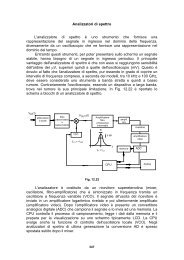
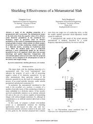
where k1= k0n r= k0µrεrand ηrµr/ εr= . It is worth noting that, when the slabthickness is chosen as h opt = λ 1 /4 (with λ 1 = λ 0 /n r ), the broadside power density ismaximum.A power enhancement factor E P,M can be defined as the ratio between the broadsidepower density radiated in the presence of the grounded slab P M (0) and that radiated infree space P M,0 (0). It can easily be shown that, under the optimum condition h = h opt , itresults E P,M = 4/η 2 r , which can thus be maximized with a low-impedance substrate (e.g.,an <strong>MNZ</strong> substrate). For the suboptimal case (h < h opt ), the enhancement factor can beexpressed as:2k0122P ( 0)8πη0cos( k1h) + jηsin( k1h)Mr4EP,M= ==(2)2P ( )( ) ( ) 2M ,00k0cos k1h+ jηrsin k1h232πη0<strong>MNZ</strong> metamaterial substrate designIn order to obtain an <strong>MNZ</strong> substrate, a metamaterial slab composed of square spiralresonators printed on RO4003C strips is considered [4]-[5]. The xyz unit-cell dimensionsare 4×6×6 mm 3 , being 6 mm the thickness of the metamaterial slab and 5.6 mm the widthof the spiral resonator. The gap between adjacent layers of spirals is 4 mm. In thesimulations, the incident electric field is linearly polarized along +y axis, this is, parallelto the dielectric strips which contain the spiral resonators. When used as a reflector, themetamaterial slab is operating around 2.6 GHz (close to the resonance). This can clearlybe seen by observing the effective parameters (extracted according to the Nicolson-Ross-Weir formulas [6]) in Figure 1. In particular, the effective permeability µ r shows aresonance at 2.58 GHz (Figure 1a). It can be observed that the <strong>MNZ</strong> band starts at 3.74GHz (where Re[µ r ]= 0) up to 6.65 GHz (where Re[µ r ] = 1).It should be noted that for very low values of Re[µ r ], the optimum thickness of the slabcan be very large. The metamaterial slab we can build is only 6 mm thick, so it isexpected that the excited leaky waves be not dominant since the structure operates undersuboptimal conditions. However, by plotting the power enhancement factor as a functionof frequency using the extracted effective medium parameters, a peak occurs around 5.5GHz for the 6 mm thick slab, as shown in Figure 2.Fabrication and MeasurementsIn order to verify the previous results, a preliminary example of a magnetic dipole hasbeen fabricated on a 2λ 0 ×2λ 0 metal ground plane. The dimensions of the slot are 29×2mm 2 , and it is tuned around 5 GHz. The performance of the antenna has been tested withand without the square spiral <strong>MNZ</strong> substrate. A photo of the slot on the ground plane anda detail of the <strong>MNZ</strong> metamaterial slab are reported in Figure 3.Complete radiation patterns have been measured in the anechoic chamber. The measuredE- and H-plane patterns of the slot with and without the <strong>MNZ</strong> metamaterial substrate areshown in Figure 4. It can be observed that an enhancement of broadside radiation isachieved at 5.7 GHz. In particular, the directivity in the E plane has significantlyAuthorized licensed use limited to: Universita degli Studi di Roma La Sapienza. Downloaded on December 30, 2008 at 07:49 from IEEE Xplore. Restrictions apply.