Rinnai Sunmaster Gas Manual - Pivot Stove & Heating
Rinnai Sunmaster Gas Manual - Pivot Stove & Heating
Rinnai Sunmaster Gas Manual - Pivot Stove & Heating

Create successful ePaper yourself
Turn your PDF publications into a flip-book with our unique Google optimized e-Paper software.
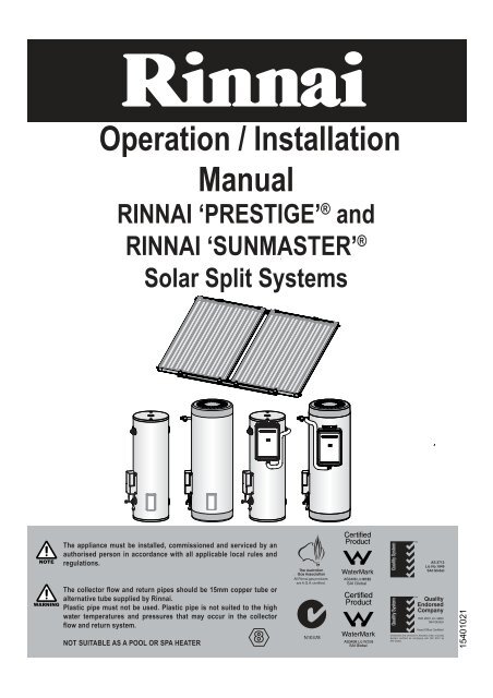
Operation / Installation<strong>Manual</strong>RINNAI ‘PRESTIGE’ ® andRINNAI ‘SUNMASTER’ ®Solar Split SystemsNOTEThe appliance must be installed, commissioned and serviced by anauthorised person in accordance with all applicable local rules andregulations.AS 2712Lic No.1849SAI GlobalWARNINGThe collector flow and return pipes should be 15mm copper tube oralternative tube supplied by <strong>Rinnai</strong>.Plastic pipe must not be used. Plastic pipe is not suited to the highwater temperatures and pressures that may occur in the collectorflow and return system.NOT SUITABLE AS A POOL OR SPA HEATERAll <strong>Rinnai</strong> gas productsare A.G.A. certified.W169SAI GlobalDistributed and serviced in Australia under a QualitySystem certified as complying with ISO 9001 bySAI Global15401021
IMPORTANT INFORMATION
TABLE OF CONTENTSIMPORTANT INFORMATION & WARNINGS ....................................................................................... 2SAFETY & REGULATORY INFORMATION...............................................................................................................................2SCALDS HAZARDS ..................................................................................................................................................................3OPERATION PRINCIPLE ..........................................................................................................................................................4SAFETY DEVICES.....................................................................................................................................................................5EXCESSIVE DISCHARGE FROM SAFETY DEVICES .............................................................................................................5WATER TEMPERATURE...........................................................................................................................................................6TURNING ‘OFF’ THE WATER HEATING SYSTEM..................................................................................................................6TURNING ‘ON’ THE WATER HEATING SYSTEM.....................................................................................................................6WATER QUALITY ......................................................................................................................................................................7DRAINING AND FILLING THE WATER HEATING SYSTEM ....................................................................................................7MAINTENANCE AND REGULAR CARE ...................................................................................................................................7SERVICING AND REPAIR.........................................................................................................................................................7SAVE A SERVICE CALL ....................................................................................................................... 8SPECIFICATIONS FOR SYSTEMS..................................................................................................... 10GENERAL ................................................................................................................................................................................10SYSTEM SPECIFICATIONS AND DIMENSIONS ...................................................................................................................10FLOW CONTROL VALVE ........................................................................................................................................................10DIFFERENTIAL TEMPERATURE CONTROLLER ..................................................................................................................10SPECIFICATIONS FOR SOLAR COLLECTORS................................................................................ 11SPECIFICATIONS FOR STORAGE CYLINDERS .............................................................................. 12SPECIFICATIONS FOR GAS BOOSTERS ......................................................................................... 16INSTALLATION & MAINTENANCE - ALL SYSTEMS........................................................................ 17REGULATIONS AND OCCUPATIONAL HEALTH AND SAFETY (OH&S) ..............................................................................17LOCATION - GENERAL INFORMATION.................................................................................................................................17STORAGE CYLINDER LOCATION .........................................................................................................................................17GAS BOOSTER LOCATION AND MOUNTING (where applicable) ........................................................................................18WATER PIPES .........................................................................................................................................................................18WATER SUPPLY......................................................................................................................................................................18HOT WATER DELIVERY TEMPERATURE..............................................................................................................................18FROST PROTECTION MODE ON SOLAR CONTROLLER....................................................................................................19VALVES & FITTINGS ...............................................................................................................................................................20REGULATIONS AND OCCUPATIONAL HEALTH AND SAFETY (OH&S) ..............................................................................21SYSTEM ORIENTATION AND INCLINATION .........................................................................................................................21SOLAR COLLECTOR ROOF MOUNTING OPTIONS .............................................................................................................22SOLAR COLLECTOR INSTALLATION COMPONENTS .........................................................................................................23STANDARD INSTALLATION....................................................................................................................................................24FRAMED INSTALLATIONS - FLAT, REVERSE & SIDE PITCH...............................................................................................27COLLECTOR FITTINGS INSTALLATIONS..............................................................................................................................28INSTALLATION OF SOLAR GAS BOOSTED SYSTEMS .................................................................. 30OVERVIEW OF SYSTEM COMPONENTS .............................................................................................................................30GAS BOOSTER LOCATION ....................................................................................................................................................30GAS SUPPLY...........................................................................................................................................................................30HOT WATER DELIVERY TEMPERATURE..............................................................................................................................30CLEARANCES .........................................................................................................................................................................44INSTALLATION PROCEDURE ................................................................................................................................................44FILLING THE SYSTEM............................................................................................................................................................45CHECKING SOLAR PUMP OPERATION................................................................................................................................45ADJUSTING FLOW CONTROL VALVE...................................................................................................................................45PRE SOLAR HEATING CHECKS ............................................................................................................................................46SOLAR HEATING ....................................................................................................................................................................47FINISHING THE INSTALLATION.............................................................................................................................................47DRAINING INSTRUCTIONS....................................................................................................................................................48INSTALLATION & MAINTENANCE - ELECTRIC BOOSTED SYSTEMS .......................................... 49OVERVIEW OF SYSTEM COMPONENTS .............................................................................................................................49ELECTRIC SUPPLY.................................................................................................................................................................49HOT WATER STORAGE AND DELIVERY TEMPERATURES ................................................................................................49INSTALLATION PROCEDURE ................................................................................................................................................54FILLING THE SYSTEM............................................................................................................................................................57CHECKING SOLAR PUMP OPERATION................................................................................................................................57ADJUSTING FLOW CONTROL VALVE...................................................................................................................................57PRE SOLAR HEATING CHECKS ............................................................................................................................................58SOLAR HEATING ....................................................................................................................................................................58FINISHING THE INSTALLATION.............................................................................................................................................58DRAINING INSTRUCTIONS....................................................................................................................................................59CONTACT INFORMATION.................................................................................................................. 61<strong>Rinnai</strong> Australia - 1 - Solar Split Systems Operating / Installation <strong>Manual</strong> Version 8 - 18/10/10
IMPORTANT INFORMATION & WARNINGSSAFETY & REGULATORY INFORMATIONWARNINGDO NOT operate this system before reading the manufacturers instructions.This appliance must be installed, commissioned and serviced by an authorised person inaccordance with all applicable local rules and regulations.Access covers of water heating system components will expose 240V wiring and MUST beremoved by an authorised person.This appliance is not intended for use by persons (including children) with reduced physical,sensory or mental capabilities, or lack of experience and knowledge, unless they have been givensupervision or instruction concerning use of the appliance by a person responsible for their safety.For continued safety of this appliance it must be installed, operated and maintained in accordancewith the manufacturers instructions.Children should be supervised to ensure they DO NOT play with the appliance.Any power leads from the water heater system components MUST BE plugged into an externalweatherproof electrical outlet. If the power supply cord of any water heating components isdamaged, it MUST BE replaced by an authorised person in order to avoid a hazard, using genuinereplacement parts available from <strong>Rinnai</strong>. Take care not to touch the power plugs with wet hands.Care should be taken not to touch the pipe work as it may be HOT! The pipes between the solarcollectors and storage cylinder MUST BE copper, or alternative material pipes that may besupplied by <strong>Rinnai</strong>. Plastic pipe is NOT suited to the water temperatures and pressures that mayoccur in the system.DO NOT place articles on or against this appliance.DO NOT store chemicals or flammable materials near this appliance.DO NOT operate with collectors or covers removed from this appliance.DO NOT activate pump unless cylinder is full of water.NEVER use a flammable spray such as hair spray, lacquer, paint, etc near this unit as this maycause a fire.NOTICE TO VICTORIAN CONSUMERSThis appliance must be installed by a person licensed with the Plumbing Industry Commission.Only a licensed person will have insurance protecting their workmanship.So make sure you use a licensed person to install this appliance and ask for your Compliance Certificate.For Further information contact the Plumbing Industry Commission on 1800 015 129.<strong>Rinnai</strong> Australia 2 Solar Split Systems Operating / Installation <strong>Manual</strong> - Version 8 18/10/10
SCALDS HAZARDSIMPORTANT INFORMATION & WARNINGSHOT WATER CAN CAUSE SCALDS.CHILDREN, DISABLED, ELDERLY AND THE INFIRM ARE AT THE HIGHEST RISK OFBEING SCALDED.FEEL WATER TEMPERATURE BEFORE BATHING OR SHOWERING.SCALDS FROM HOT WATER TAPS CAN RESULT IN SEVERE INJURIES TO YOUNGCHILDREN.SCALDS OCCUR WHEN CHILDREN ARE EXPOSED DIRECTLY TO HOT WATER WHENTHEY ARE PLACED INTO A BATH WHICH IS TOO HOT.ALWAYS......Test the temperature of the water with your elbow before placing your child in the bath, also carefully feelwater before bathing or showering yourself.Supervise children whenever they are in the bathroom.Make sure that the hot water tap is turned off tightly.CONSIDER.....Installing child proof tap covers or child resistant taps (both approaches will prevent a small hand beingable to turn on the tap).Installing tempering valves or thermostatic mixing valves which reduce the hot water temperaturedelivered to the taps. Your local plumbing authority may already require that these be fitted. Contact yourinstaller or local plumbing authority if in doubt.NEVER….Leave a toddler in the care of another child. They may not understand the need to have the watertemperature set at a safe level.<strong>Rinnai</strong> Australia 3 Solar Split Systems Operating / Installation <strong>Manual</strong> Version 8 - 18/10/10
OPERATION PRINCIPLEIMPORTANT INFORMATION & WARNINGSThis system is designed to have the solar collectors on the roof and the storage cylinder installed at ground or floorlevel.Electric and <strong>Gas</strong> boosted models are available. The system comprises a hot water storage cylinder, solarcollectors, pump circulation system solar control unit and temperature sensors. The solar control unit ensureswater circulates between the solar collectors and the storage cylinder to transfer heat from the solar collectors tothe water in the cylinder if enough heat is available from the sun.Supplementary heating is provided if insufficient heat is available from sun (such as during cloudy or rainy weatheror during winter months) either via an electric heating element(s) located inside the storage cylinder or via a on inline<strong>Gas</strong> booster located external to the storage cylinder. The following diagrams illustrates the Split Solar HotWater System set up for both the Electric and <strong>Gas</strong> boost.TO HOT WATEROUTLETSPUMP & SOLARCONTROL MODULECOLD WATERSUPPLYGAS SUPPLYTO HOT WATEROUTLETSPUMP & SOLARCONTROL MODULECOLD WATERSUPPLYELECTRIC ELEMENTFigure 1. <strong>Sunmaster</strong> <strong>Gas</strong> Boosted Hot Water SystemsFigure 2. <strong>Sunmaster</strong> Electric Hot Water SystemsTO HOT WATEROUTLETSGAS SUPPLYTO HOT WATEROUTLETSPUMP & SOLARCONTROL MODULEPUMP & SOLARCONTROL MODULECOLD WATERSUPPLYCOLD WATERSUPPLYELECTRIC ELEMENTFigure 3. Prestige <strong>Gas</strong> Hot Water SystemsFigure 4. Prestige Electric Hot Water Systems<strong>Rinnai</strong> Australia 4 Solar Split Systems Operating / Installation <strong>Manual</strong> - Version 8 18/10/10
IMPORTANT INFORMATION & WARNINGSSAFETY DEVICESThe water heating system is supplied with various safety devices including temperature sensors, overheat sensorsand switches and a Pressure & Temperature Relief (PTR) valve. These devices must not be tampered with orremoved. The water heating system must not be operated unless each of these devices is fitted and is in workingorder.DO NOT tamper with or remove safety devices.WARNINGDO NOT operate the water heater unless all safety devices are fitted and in working order.DO NOT block or seal the PTR Valve and drain pipe.Pressure & Temperature Relief (PTR) ValveThis valve is located near the top of the water heaterand is essential for safe operation. It is normal for thevalve to release a small quantity of water through thedrain line during heating.However, continuous leakage of water from thevalve and its drain line may indicate a problem withthe water heater.Twist cap until waterflows from drain lineLift lever until waterflows from drain line(Lower lever gently!)WARNINGNever block the outlet of the PTR valve or it’s drain line for any reason. The easing gear must beoperated at least every 6 months to remove lime deposits and verify that it is not blocked. Failureto do this may result in the water heater failing.If the valve does not discharge water when the easing gear lever is opened, or does not seal againwhen the easing gear is closed, attendance by an authorised person must be arranged withoutdelay. The PTR valve is not serviceable.EXCESSIVE DISCHARGE FROM SAFETY DEVICESPressure & Temperature Relief (PTR) ValveIt is normal and desirable that this valve allows a small quantity of water to be discharged during the heating cycle.If it discharges more than a bucket of water during a 24 hour period or discharges continuously there may beanother problem.If the valve dribbles continuously, try easing the valve gear for a few seconds as described above. This maydislodge any foreign matter and alleviate the problem.If the valve discharges at high flows, especially at night, it may be as a result of the water pressure exceeding thedesign pressure of the water heater. Ask your installer to fit a Pressure Limiting Valve (PLV).WARNINGNEVER replace the PTR valve with one which has a higher pressure rating than is specified for yourwater heater.Expansion Control Valve (ECV) - if fittedIt is normal and desirable that this valve allows a small quantity of water to be discharged during the heating cycle.If it discharges more than a bucket of water during a 24 hour period or discharges continuously there may beanother problem.If the valve leaks continuously, try easing the valve gear for a few seconds. This may dislodge any foreign matterand alleviate the problem. If this does not alleviate the problem contact <strong>Rinnai</strong>.Operate the easing gear regularly to remove any lime deposits and to verify that it is not blocked.<strong>Rinnai</strong> Australia 5 Solar Split Systems Operating / Installation <strong>Manual</strong> Version 8 - 18/10/10
IMPORTANT INFORMATION & WARNINGS<strong>Gas</strong> boosted models• Do not touch the flue outlet or do not insert any objects into the flue outlet.• Keep flammable materials, spray cans, fuel containers, trees, shrubs and poolchemicals etc. well clear of the flue outlet.• Do not use the gas types other than those designated on the data plate. Forexample, do not use Propane/Butane gas mixtures on appliances marked Propane<strong>Gas</strong>.HOT!• Do not use Propane gas on appliances marked as Natural gas and vice versa.Hydrogen <strong>Gas</strong>In the case of systems using a vitreous enamelled lined cylinder, if the hot water unit is not used for two weeks ormore, a quantity of hydrogen gas, which is highly flammable, may accumulate in the water heater. To dissipate thissafety, it is recommended that a non electrically operated hot tap be turned on for two minutes at a sink, basin, orbath, but not a dishwasher or other appliance. during this procedure there must be no smoking, open flame or anyelectrical appliance operating nearby. If hydrogen is discharged through the tap, it will probably make a sound likeair escaping.WATER TEMPERATUREThe solar control unit and pump ensure water circulates between the solar collectors and storage cylinder until thewater at the base of the cylinder reaches approximately 65°C. Under these conditions water at the hot outlet mayexceed 85°C. During periods of low solar gain supplementary heating occurs to a minimum of 60°C as required.IMPORTANTTo meet Australian regulatory requirements, supplementary heating temperature settingsmust be at least 60°C.TURNING ‘OFF’ THE WATER HEATING SYSTEMIf you plan to be away for only a few nights, we suggest you leave the water heating system switched on. If it isnecessary to switch off the water heater, do so as outlined below:Electric Boosted systems• Switch off the electric supply to the supplementary heating element. The switch is usually marked andlocated in the electricity meter box of the dwelling.• Switch off the electric supply to the solar controller and pump.<strong>Gas</strong> Boosted systems• Switch off the electric supply to the gas booster.• Switch off the electric supply to the solar controller and pump.TURNING ‘ON’ THE WATER HEATING SYSTEMElectric Boosted system• Switch on the electric supply to the supplementary heating element(s). The switch is usually marked andlocated in the electricity meter box of the dwelling.• Switch on the electric supply to the solar controller pump. Electric and solar water heating will now occur asrequired. It may take a number of hours before hot water is available.<strong>Gas</strong> Boosted systems• Switch on the electric supply to the gas booster.• Switch on the electric supply to the solar controller and pump. Solar water heating will now occur. Hotwater is available immediately from the gas booster when hot water tap is opened, irrespective of solarheat gain.<strong>Rinnai</strong> Australia 6 Solar Split Systems Operating / Installation <strong>Manual</strong> - Version 8 18/10/10
WATER QUALITYThe water quality of most public supplies is suitable for the water heating system. The water quality from bore wellsis generally unsuitable for the water heating system. Refer to separate 'Warranty Terms and Conditions' documentfor water quality parameters and how they affect the warranty conditions. If in doubt about the water quality, haveit checked against the parameters listed in the warranty conditions. The system is not suitable as a pool or spaheater.DRAINING AND FILLING THE WATER HEATING SYSTEM• Draining or filling normally occur only during installation or servicing and must be carried out by anauthorised person.MAINTENANCE AND REGULAR CAREOperate the easing gear of the PTR as described under “SAFETY DEVICES” on page 5.The overflow tray (supplied by installer) and drain underneath the storage cylinder (if fitted) should be periodicallychecked to ensure there are no blockages.SERVICING AND REPAIRIMPORTANT INFORMATION & WARNINGSOur Servicing network personnel are fully trained and equipped to give the best service on your appliance. If yourappliance needs service, ring one of the service contact numbers on the back of this booklet.It is recommended that the system be serviced at least every 5 years.The pressure and temperature relief valve and expansion control valve must be checked for performance orreplaced by an authorised person at intervals not exceeding 5 years or more frequently in areas where the wateris classified as scaling water (refer to ‘Warranty Terms and Conditions’ document - ‘Water Quality’).It is recommended that the sacrificial anode fitted to <strong>Sunmaster</strong> cylinders be inspected very 5 years or morefrequently in areas where there is a high incidence of water deposits. This does not apply to <strong>Rinnai</strong> Prestigecylinders. Anodes suited to hard and soft water, are available from <strong>Rinnai</strong>.If the electric conduit, power supply cord or plug to the water heater is damaged, they must be replaced by anauthorised person in order to avoid a hazard. The power supply cord and plug (if fitted) must be replaced by agenuine replacement part available from <strong>Rinnai</strong>.<strong>Rinnai</strong> Australia 7 Solar Split Systems Operating / Installation <strong>Manual</strong> Version 8 - 18/10/10
SAVE A SERVICE CALLSAVE A SERVICE CALLBefore calling <strong>Rinnai</strong> for service, perform the fault finding steps in the Table 1. If the problem persists, contact<strong>Rinnai</strong>.Service calls attending to any condition or fault that is not related to the <strong>Rinnai</strong> product and components maybe chargeable.Table 1 - TroubleshootingProblem Cause RemedyInsufficient or no hot Water Booster heating not operatingOrInsufficient gas supply for gas boosted heatingsystemExcessive hot water consumptionIncorrect Solar system sizeTemperature and pressure relief valve /Expansion Control valvedischarging water continuouslyElectric boosted Systems: Check to ensure the electric isolating switch(es) at the switchboard (usually marked"Hot water" or "water heater") is switched 'ON'.Check to ensure that the electric fuses for hot water at the switchboard are intact.<strong>Gas</strong> Boosted Systems: Check to ensure the power cord of the gas booster is plugged in and the power pointswitched 'ON'.Check gas is available and turned ON'.Close the hot tap and wait for 10 seconds and open it again. The hot tap must beopened enough to ensure that the flow rate is not less than 2.4 L/min. gas the gas booster burners will not light if it is less than 2.4 L/min. Check theisolation valve in the gas line is opened.If there is gas supply to other appliances in the rest of the house, try lighting anothergas appliance.Refer to your plumber to ensure the gas line has been purged of air after installation.Electric Boosted Systems:If the water goes cold, are you using more hot water than you think? Often endusers are surprised at the amount of hot water used, especially when showering. Ifthe amount of hot water used during the day exceeds the storage capacity of thecylinder, it is likely that there will be insufficient hot water. Has your plumber installwater saving fixtures and/or flow control or pressure limiting valves to reduceconsumption.<strong>Gas</strong> Boosted Systems:Insufficient flow may occur if multiple outlets are in use at the same time and exceedthe rated flow capacity of the gas booster. If so, reduce the number of outlets in use.Have your plumber install water saving fixtures and/or flow control or pressurelimiting valves to reduce consumption.Check correct size gas booster is fitted.Do you have the correct system size and configuration for your requirements? Referto <strong>Rinnai</strong> literature for information.Pressure and Temperature Relief (PTR) valveIt is normal and desirable that this valve allows a small quantity of water to bedischarged during the heating cycle. If it discharges more than a bucket of waterduring a 24 hour period or discharges continuously there may be another problem.If the valve dribbles continuously, try easing the valve gear for a few seconds asdescribed under 'Regular Care'. This may dislodge any foreign matter and alleviatethe problem.If the valve discharges at high flows, especially at night, it may be as a result of thewater pressure exceeding the design pressure of the water heater. Ask your installerto fit a Pressure Limiting Valve (PLV).WARNINGInsufficient or no hot WaterContinued• Never replace the PTR valve with one which has a higher pressure rating than is specified for your water heater.• If the valve discharges hot water at high flows, (dumps) there may be a serious problem. Switch off the powersupply in the meter box (the switch marked ‘WATER HEATER’ or ‘HOT WATER’) or the isolating switch installednear the water heater and contact <strong>Rinnai</strong>.Expansion Control Valve (ECV) - if fittedIt is normal and desirable that this valve allows a small quantity of water to bedischarged during the heating cycle. If it discharges more than a bucket of waterduring a 24 hour period or discharges continuously there may be another problem. If the valve leaks continuously, try easing the valve gear for a few seconds asdescribed under 'Regular Care'. This may dislodge any foreign matter and alleviatethe problem. If this does not alleviate the problem contact <strong>Rinnai</strong>.<strong>Rinnai</strong> Australia 8 Solar Split Systems Operating / Installation <strong>Manual</strong> - Version 8 18/10/10
Problem Cause RemedyInsufficient or no hot WatercontinuedNo Water from the hot tap<strong>Gas</strong> Booster operating toofrequentlySAVE A SERVICE CALLBooster element Thermostat SettingsRestriction in the hot tap or failure of the cold watersupply to the water heater.Insufficient Sunlight - Collectors shadedElectric Boosted Systems:The end user can check the temperature of hot water delivered with athermometer placed under the closest non tempered outlet (usually the kitchensink).CAUTION: Take care to avoid scalding. This test should be done early inthe morning after overnight electrical boosting before any hot water isused. The temperature of the water delivered should be at least 55° C(allowing for heat losses in pipe work). If this is not the case or the temperature needs to be increased contact <strong>Rinnai</strong>.The thermostat settings of the heating element thermostat can also be confirmeddirectly by a qualified person as described under 'hot water storage & deliverytemperature'. The settings can be increased if required. Contact <strong>Rinnai</strong>.<strong>Gas</strong> Boosted Systems:The delivery temperature of gas boosted systems is normally 60 or 65°C. Ifftemperatures are higher than this, the flow of water through the gas booster willreduce and may result in insufficient flow rate.The end user can check the temperature of hot water delivered with athermometer placed under the closest outlet (usually the kitchen sink).CAUTION: Take care to avoid scalding. If the temperature is higher than65°C the gas booster may be preset incorrectly. Contact <strong>Rinnai</strong>.Check for water flow at the other taps and that the cold water isolation is fullyopen.Ensure the trees or other objects are not shading onto the collector surface (Trimthe trees or relocate the solar collector if the obstruction is permanent).Make sure the glass on the collector is not dirty.High electricity or gas bill Excessive hot water consumption See entry under 'Insufficient hot water'.Solar Control unit switched offIf the solar control unit is switched off there will be no solar pre-heating of waterresulting in the water being heated entirely by electricity or gas' boosting'. Checkthe power outlet for the solar control unit is switched on.Temperature and pressure relief valve / Expansion See entry under 'Insufficient hot water'.Control valve discharging water continuouslyLack of solar gainReduced sunlight:Reduced sunlight due to overcast weather in summer or low solar contribution inwinter will result in an increased dependence on electricity or gas boosting.Higher electricity or gas bills under these conditions, especially in winter, arenormal.Collectors shaded:If the solar collectors are shaded by trees or other objects, or the glass is dirty,the effectiveness of the collectors is greatly reduced. Arrange for trimming of thetrees or relocation of the solar collectors if the obstruction is permanent. Arrangefor cleaning of the collector glass.Solar collectors incorrectly positionedCheck that positioning and alignment of solar collectors is in accordance with thesection 'Location and alignment of solar collectors'.WARNING: Persons working from elevated surfaces such as roofs must beadequately trained an qualified in accordance with local OH&S requirements.High Electricity Tariffs (electric boosted systems only) Electric Boosted SystemsThe electricity tariff will determine the running costs of the system. It is importantthe end user is aware of the applicable tariffs. Contact your electricity supplier toconfirm what these tariffs are.Little or no water circulation in the solar 'flow andreturn' loopThere are numerous causes of little or no circulation in the solar 'flow and returncircuit the circulation of water through the collectors. These causes must beinvestigated by a qualified person. Contact <strong>Rinnai</strong>.Water flow fluctuations One or more hot taps opened at the same time More than one or two hot taps in use at the same time may cause a decrease inthe hot water flow from the taps.Is there more than one or two hot taps open, or are appliances such as adishwasher or washing machine, in use at the same time?Ensure only one or two hot taps are on at one time.Check the flow of the water from one tap, eg. the shower. The shower should beadjusted so the hot tap is fully open.Water Hammer Hot and cold water plumbing in the premises Have a plumber check clipping of hot and cold water pipework and install apressure limiting valve and water hammer arrestor as required.<strong>Rinnai</strong> Australia 9 Solar Split Systems Operating / Installation <strong>Manual</strong> Version 8 - 18/10/10
GENERALSPECIFICATIONS FOR SYSTEMSSplit solar hot water systems are specified according to the grade of storage cylinder material, cylindercapacity, number of solar collectors and boost type and capacity. Boost capacity for gas boostedsystem depends on the gas booster model selected. Boost capacity for electrically boosted systemsdepends on the power rating of electric heating elements and whether one or two electric heatingelements are fitted.SYSTEM SPECIFICATIONS AND DIMENSIONSSpecifications and principal dimensions for the various systems and components are shown below.Table 2 - System SpecificationsSystem Type<strong>Rinnai</strong> ‘<strong>Sunmaster</strong>’SystemsSG175, SG215,SE160, SE200<strong>Rinnai</strong> ‘<strong>Sunmaster</strong>’SystemsSG270, SG340,SE315<strong>Rinnai</strong> ‘Prestige’SystemsConnections:Solar flow and return 1/2” 1/2” 1/2”PTR Valve 1/2” 1/2” 3/4”Cold Inlet 3/4” 3/4” 3/4”Hot Outlet 3/4” 3/4” 3/4”PTR Valve setting (kPa) 1000 850 850Rating of PTR Valve supplied (kW) 10 10 10Expansion Control Valve (ECV) setting850 700 700(kPa)Max supply pressure with ECV (kPa) 680 550 560Max supply pressure without ECV800 680 700(kPa)Pressure limiting valve rating (kPa)(supplied by installer if required)500 500 500FLOW CONTROL VALVEA flow control valve is fitted to the pump and controller assembly.It’s purpose is to allow the water flow rate through the collector collectors and storage cylinder to becontrolled to optimise the performance of the system.DIFFERENTIAL TEMPERATURE CONTROLLERThe primary task of the differential temperature controller is to control the operation of the pump tooptimize solar energy collection. This task is performed by measuring the temperature differentialbetween the hot sensor and the cold sensor. When the differential exceeds 9°C the pump is activatedand water passes through the collectors collecting solar energy. When the differential falls below 5°Cthe pump is shut down.A secondary task of the controller is to stop energy collection when the cylinder is full of hot water.This is referred to as no load protection and the pump is shut down if the temperature of the watergoing to the collectors exceeds 65°C. At such a temperature in the base of the cylinder, thetemperature of water in the top of the cylinder is expected to be about 85°C.<strong>Rinnai</strong> Australia - 10 - Solar Split Systems Operating / Installation <strong>Manual</strong> - Version 8 - 18/10/10
SPECIFICATIONS FOR SOLAR COLLECTORSTable 3 - Model Numbers and SpecificationsCHARACTERISTICSEnduro / Equinox(SP200A) or(SP200A FTC)Excelsior(EXT OR EXT FTC)E-FROST(HPFTC- 8-10)TYPE Flat plate Flat plateFlat Plate /Heat PipeCONSTRUCTION- Waterways Copper Copper Copper- Absorber Aluminium Copper Aluminium- Selective Surface High Performance Sputtered Titanium Oxide High PerformanceMaximum OperatingPressureCasing MaterialOverall Dimensions(L x W x H) (mm)1940 x1025 x80Aluminium1964 x1047 x811940 x1025 x80Weight empty(STD/FTC) (kg).33 / 35 35 / 38 34Water volume (Litres) 1.3 1.5 0.6Number risers 8 10 10Potential Solar Output atPTR relief conditions (kW)MODEL NUMBERS AND SPECIFICATIONS850 kPaApproximate Roof space Required: Length x Width- 1 Collector (mm) 1940 x 1025 1940 x 1047 1940 x 1025- 2 Collectors (mm) 1940 x 2130 1940 x 2174 1940 x 2130- 3 Collectors (mm) 1940 x 3235 1940 x 3301 1940 x 3235Frost Protection to -12°C.Frost Protection1.25* Standard version - no frost protectionFTC Version Frost Protection to -5°C* FOR MORE INFORMATION ON FROST PROTECTIONREFER TO WARRANTY BOOKLETPower must be on at thepump and the controllermust be in low temperaturemode(refer page 19).<strong>Rinnai</strong> Australia - 11 - Solar Split Systems Operating / Installation <strong>Manual</strong> - Version 8 - 18/10/10
SPECIFICATIONS FOR STORAGE CYLINDERSSUNMASTER GAS - VITREOUS ENAMELSG175 SG215 SG270 SG340Cylinder Height 1530 1825 1265 1510PTR / Solar Return 1310 1605 985 1200Flow line to collectors 665 665 700 700Cold Water Inlet 225 225 260 260<strong>Gas</strong> Supply and Hot Water Outlet 940 1235 675 920<strong>Gas</strong> Booster Flue Outlet 1400 1695 1135 1380Diameter 515 515 685 685Weight Empty (kg) 66 88 95 103SOLARRETURNP&TR VALVECYLINDER HEIGHTP&TR / SOLAR RETURNFLOW LINE TO COLLECTORSCOLDWATERINLETGAS SUPPLY ANDHOT WATER OUTLETGAS BOOSTER FLUE OUTLETCYLINDER DIAMETERTEMPERATURE SENSORDRY WELLSYSTEM DEPTHFigure 5 - Dimensional Drawing - <strong>Rinnai</strong> <strong>Sunmaster</strong> Vitreous Enamel Storage Cylinder -<strong>Gas</strong> Boosted Split Systems<strong>Rinnai</strong> Australia - 12 - Solar Split Systems Operating / Installation <strong>Manual</strong> - Version 8 - 18/10/10
SPECIFICATIONS FOR STORAGE CYLINDERSSUNMASTER - ELECTRIC - VITREOUS ENAMELSE160 SE200 SE315PTR / Solar Return / Hot Water Outlet 1310 1605 1200Flow line to Collectors 665 665 700Cold Water Inlet 225 225 260Cylinder Height 1530 1825 1510Diameter 515 515 685Weight Empty (kg) 71 83 100SOLARRETURNP&TR VALVEPTR / SOLAR RETURNFLOW LINE TO COLLECTORSCOLDWATERINLETHOT WATER OUTLETCYLINDER HEIGHTCYLINDER DIAMETERTEMPERATURESENSORDRY WELLFigure 6 - Dimensional Drawing - <strong>Rinnai</strong> <strong>Sunmaster</strong> Vitreous Enamel Storage Cylinder- Electric Boosted Split Systems<strong>Rinnai</strong> Australia - 13 - Solar Split Systems Operating / Installation <strong>Manual</strong> - Version 8 - 18/10/10
SPECIFICATIONS FOR SOLAR COLLECTORSPRESTIGE GAS - STAINLESS STEEL250 315Cylinder Height 1700 2090PTR / Solar Return / Hot Water Outlet 1490 1880<strong>Gas</strong> Supply and Hot Water Outlet 880 1270<strong>Gas</strong> Booster Flue Outlet 1345 1735Weight Empty (kg) 56 68CYLINDER HEIGHTP&TR VALVE650SOLARRETURNGAS SUPPY ANDHOT WATER OUTLETGAS BOOSTER FLUE OUTLET300210COLD WATERINLET600795Figure 7 - Dimensional Drawing - <strong>Rinnai</strong> Prestige Stainless Steel Storage Cylinder- <strong>Gas</strong> Boosted Split systems<strong>Rinnai</strong> Australia - 14 - Solar Split Systems Operating / Installation <strong>Manual</strong> - Version 8 - 18/10/10
SPECIFICATIONS FOR SOLAR COLLECTORSPRESTIGE ELECTRIC - STAINLESS STEEL160 250 315PTR / Solar Return / Hot Water Outlet 995 1490 1880Cylinder Height 1205 1700 2090Weight Empty (kg) 44 56 68P&TR VALVE & HOT WATER OUTLET650SOLARRETURNCYLINDER HEIGHT300210COLDWATERINLET600Figure 8 - Dimensional Drawing - <strong>Rinnai</strong> Prestige Stainless Steel Storage Cylinder- Electric Boosted Split systems<strong>Rinnai</strong> Australia - 15 - Solar Split Systems Operating / Installation <strong>Manual</strong> - Version 8 - 18/10/10
SPECIFICATIONS FOR GAS BOOSTERSTable 4 - Specifications - <strong>Gas</strong> BoostersModel Name: S20 S26Boost Capacity:- L/min. @ 20°C rise- L/min @ 25°C rise(L/min)Maximum Rated Flow: (L/min) 20 26Minimum Supply Pressure for Maximum rated flow: (kPa) 120 200(1)Minimum Flow for Operation: (L/min) 2.4 2.4Frost Protection: Yes Yes<strong>Gas</strong> Consumption (Maximum / Minimum): (MJ/hr.) 125 - 18 188 - 23Star Rating (AS 4552 - 1998): 5.5 5.0Hot Water Delivery Temperature: (2) 60°C 60°CDimensions: Height x Width x Depth: (mm) 530 x 350 x 194 530 x 350 x 194Weight: (Kg) 15 21(1) - Units will operate at lower pressures but the rated flow with not be achieved.(2) - <strong>Gas</strong> boosters for Solar hot water applications should be preset to deliver a minimum temperature of 60°C.<strong>Gas</strong> boosters factory pre set to 60°C or 65°C will be marked as such. If there are no temperature markings on the waterheater, on site conversion is required. This is a simple procedure, contact your Service Agent.20162624<strong>Rinnai</strong> Australia - 16 - Solar Split Systems Operating / Installation <strong>Manual</strong>- Version 8 - 18/10/10
INSTALLATION & MAINTENANCE - ALL SYSTEMSREGULATIONS AND OCCUPATIONAL HEALTH AND SAFETY (OH&S)WARNINGInstallation and commissioning must be performed by authorised persons. Solar systems must be installed in accordance with these instructions and allregulatory requirements which exist in your area including those in relation tomanual lifting, working at heights and on roofs. Applicable publications andregulations may include:• AS 5601 <strong>Gas</strong> Installations• AS/NZS 3500 National Plumbing and Drainage• AS/NZS 3000 Wiring rules• Building Codes of Australia (BCA)• Local Occupational Health and Safety (OH&S) regulationsThis appliance is not suitable for use as a domestic spa pool or swimming poolheater.Solar collectors are heavy and bulky items and are usually positioned on theroofs of buildings. Australian State and Territories have a principal OccupationalHealth and Safety (OH&S) Act which contains requirements relating to thehandling of large, bulky or awkward items and the prevention of falls fromelevated surfaces. Persons installing solar collectors must be aware of theirresponsibilities and be adequately trained and qualified, in accordance withlocal OH&S requirements.LOCATION - GENERAL INFORMATIONAll system components must be in an accessible location. The storage cylinder must be accessiblewithout the use of a ladder or scaffold. Sufficient clearances shall allow access to, and removal of,all serviceable parts. Ensure the PTR valve, pump kit, drain lines and thermostat and elements forelectric systems have sufficient clearances and are accessible for service and removal. Theinformation on any data plates must also be readable. In the case of vitreous enamel lined cylinders,leave a clearance of the height of one storage cylinder above the cylinder being installed so thesacrificial anode can be inspected and replaced. This does not apply to stainless steel cylinders.Select suitable areas of roof on which to install the solar collectors as close as practicable to thecylinder. Ensure that the area is even and without cracked or damaged tiles. Collectors should bepositioned for optimum solar benefit. Refer to the section 'INSTALLATION OF SOLARCOLLECTORS' for more information.The solar pump kit and gas booster heater require an AC 240V power supply. A weatherproof 240V,10A earthed power point must therefore be provided adjacent to these. All electrically boosted solarhot water heating elements must be connected to an independent, fused, AC 240V 50 Hz powersupply with an isolating switch installed at the switch board.STORAGE CYLINDER LOCATIONThe storage cylinder should be placed as close as practicable to the most frequently used hot wateroutlet point or points to minimise the delay time for hot water delivery. This will usually be the kitchentap.The solar storage cylinders have an ingress protection rating of IPX4 making them suitable forinternal or external installation. <strong>Rinnai</strong> 'external' gas boosters are suitable for external installationonly.Storage cylinders must be installed in freestanding mode on a level and stable base. For externalinstallations, storage cylinders should be mounted on a concrete base at least 50mm thick or on wellseasoned, evenly spread hardwood slats with a thickness of at least 25mm. Where property damagecan occur, storage cylinders should be installed with an approved safe tray (overflow tray).Ensure the cylinder does not stand on wet surfaces.<strong>Rinnai</strong> Australia - 17 - Solar Split Systems Operating / Installation <strong>Manual</strong> - Version 8 - 18/10/10
GAS BOOSTER LOCATION AND MOUNTING (where applicable)The gas booster is designed for 'Outdoor' Installation only. As such, it must be located in an aboveground open air situation with natural ventilation, without stagnant areas, where gas leakage andproducts of combustion are rapidly dispersed by wind and natural convection. WATER PIPESAll hot water pipework should be insulated with sealed Polyethylene foamed or equivalent insulationto optimise performance and energy efficiency. Such insulation may also be mandatory under localregulations. With the exception of solar collector flow and return pipes, water pipe sizing should beperformed in accordance with AS/NZS 3500.The collector flow and return pipes should be a minimum of 15 mm copper tube.Plastic pipe must not be used. Plastic pipe is not suited to the high waterWARNING temperatures and pressures that may occur in the collector flow and returnsystem.The maximum recommended combined lengths of the solar flow and return pipes are as follows:Table 5 - Collector Flow and Return Pipe SizingPipe Size 1 Collector 2 Collectors 3 CollectorsDN 15 (metres) 60 50 30DN 20 (metres) Not recommended 60 40WATER SUPPLYINSTALLATION & MAINTENANCE - ALL SYSTEMSThe minimum and maximum water pressures for the various systems are listed in Table 2. Approvedpressure limiting valves may be required if the 'Maximum' rated water supply pressures areexceeded. For gas boosted systems to achieve the rated flow through the outlet of the continuousflow water heater, the minimum water supply pressures must be supplied. The systems will operateat lower pressures but the rated flow will not be achieved.Water chemistry and impurity limits are detailed in the separate Warranty document. Mostmetropolitan water supplies fall within these requirements. If you are unsure about water quality,contact your water authority. If sludge or foreign matter is present in the water supply, a suitable filtershould be incorporated in the water supply to the storage cylinder.HOT WATER DELIVERY TEMPERATURELocal regulations and/or the requirements of AS/NZS3500.4 must be considered regarding thetemperature limitations of hot water supplied to areas used primarily for personal hygiene. Thetemperature of water to these areas is limited to 45°C for early childhood centres, primary andsecondary schools and nursing homes or similar facilities for young, aged, sick or people withdisabilities and 50°C for all other buildings. To comply with these requirements, a temperaturelimiting device, such as a thermostatic mixing or tempering valve, will be required on all solar hotwater systems as detailed in Figures 9 and 10.Solar collectors<strong>Rinnai</strong> gas continuousflow water heater forsolar applications,preset to deliverhot water at a fixedtemperature of 60°C or higherSolar collectorsCold water supplySolar cold water inletStoragecylinderSolar hot water returnHeated water from storage cylinder<strong>Gas</strong> boostHot water outletCold Inlet<strong>Gas</strong> supplyKitchen Laundry Ensuite BathroomTLDNote: TLD = Temperature Limiting DeviceCold water supplySolar cold water inletElectricallyboostedstoragecylinderSolar hot water returnHeated water from storage cylinderKitchen Laundry Ensuite BathroomTLDNote: TLD = Temperature Limiting DeviceFigure 9 - Tempered gas hot water systemsFigure 10 - Tempered Electric hot water systems<strong>Rinnai</strong> Australia - 18 - Solar Split Systems Operating / Installation <strong>Manual</strong> - Version 8 - 18/10/10
INSTALLATION & MAINTENANCE - ALL SYSTEMSFROST PROTECTION MODE ON SOLAR CONTROLLER• The Solar Controller has two different temperature modes. Low temperature mode andstandard operating mode.• Systems installed with E-Frost Collectors MUST be set to low temperature mode for thewarranty on the collector be valid. Refer warranty booklet for more details.• Systems with other types of collectors should be set to standard operating mode.• The factory default is Low Temperature Mode.Figure 11 - Frost Protection on SolarCollectorFigure 12 - Dip Switches K1 & K2Mode Dip Switch K1 Dip Switch K2Standard Operating Mode SOM ‘ON’ CIRLow temperature Mode LTM ‘ON’ CIRWARNING• Power MUST be turned OFF to the Controller before opening the controllerbox.• Power MUST be OFF when adjusting Dip Switches.<strong>Rinnai</strong> Australia - 19 - Solar Split Systems Operating / Installation <strong>Manual</strong> - Version 8 - 18/10/10
INSTALLATION & MAINTENANCE - ALL SYSTEMSVALVES & FITTINGSThe following valves and fittings are supplied with your solar hot water system:• A combined pressure and temperature (PTR) relief valve, capacity 10 kW. Relief valve pressure settings vary with models. This valve is fitted at the top of the storagecylinder. The PTR valve is a safety device and it is mandatory that it is fitted by the installer in allinstallations.• A non return valve fitted on the solar pump outlet to prevent backflow through the pump fromthe solar collectors. This valve is factory connected.• For gas boosted systems, elbow connections for the hot, cold and gas supply are fitted at thebottom of the gas booster.• Fittings as shown in Figures 32 - 36 and 40 - 41.The following valves & fittings are to be supplied by the installer:• A cold water expansion control valve (ECV). An ECV must be fitted in Western Australia andSouth Australia to the cold water supply to the storage cylinder to comply with local regulations.An ECV is recommended in all other geographical areas where the water supply has atendency to cause scaling. This will reduce hot water discharge from the Pressure andTemperature Relief (PTR) valve which minimises wear on this valve.• A stop cock, non return valve and line strainer. Combination valves incorporating two or moreof these functions (such as 'Trio' valves) are suitable. These are fitted to the cold water supplyto the storage cylinder by the installer.• Cold water supply and hot water discharge pipework to and from the storage cylinder.• Solar collector flow and return pipes and storage cylinder connections.• An isolating valve and connection union for the gas supply to the gas booster.• A approved pressure limiting valve (supplied with some systems) is required if the maximumrated water supply pressure in Table 2 is exceeded.<strong>Rinnai</strong> Australia - 20 - Solar Split Systems Operating / Installation <strong>Manual</strong> - Version 8 - 18/10/10
REGULATIONS AND OCCUPATIONAL HEALTH AND SAFETY (OH&S)Installation and commissioning must be performed by authorised persons. <strong>Rinnai</strong> solar systems must beinstalled in accordance with these Instructions and all regulatory requirements which exist in your areaincluding those in relation to manual lifting, working at heights and on roofs. Applicable publications andregulations may include:• AS 5601 <strong>Gas</strong> Installations• AS/NZS 3500 National Plumbing and Drainage• AS/NZS 3000 Wiring rules• Building Codes of Australia• Local Occupational Health and Safety (OH&S) regulationsWARNINGINSTALLATION OF SOLAR COLLECTORS• Solar collectors are heavy and bulky items and are usually positioned on theroofs of buildings. Each Australian State and Territory has a principalOccupational Health and Safety (OH&S) Act which contains requirementsrelating to the handling of large, bulky or awkward items and the prevention offalls from elevated surfaces. Persons installing solar collectors must be awareof their responsibilities and be adequately trained and qualified, in accordancewith local OH&S requirements.SYSTEM ORIENTATION AND INCLINATIONThe performance of any solar hot water system is determined by the way that the system is installed.In Australia, the solar collectors should face the equator (North) as shown below. Where this orientationis not practical, collectors facing within 45 degrees from North (between North-East and North-West) areaacceptable, with a reduction in efficiency of approximately 5%. If the bulk of hot water consumption occursbefore 2 pm face the collectors in a North - Easterly direction. If the bulk of hot water consumption occursafter 2 pm face the collectors in a North Westerly direction.(Ideal gives 3 hours either side of noon day sun)North45 o 45 oWestEastSouthFigure 13 - Orientation Angle of CollectorsThe inclination of the solar collectors should ideally be the same as the latitude angle of the site.Inclinations within 20 degrees of the latitude angle of the site are acceptable, with a reduction in efficiencyof approximately 5%.NorthCity Latitude +/- 20 oFigure 14 - Inclination of Collector<strong>Rinnai</strong> Australia - 21 - Solar Split Systems Operating / Installation <strong>Manual</strong> - Version 8 - 18/10/10
INSTALLATION OF SOLAR COLLECTORSTable 6: Latitudes of Australian CitiesCity Latitude City Latitude City Latitude City LatitudeAdelaide 35°S Cairns 17°S Hobart 42°S Port Hedland 20°SAlice Springs 24°S Canberra 35°S Mildura 34°S Rockhampton 24°SBrisbane 27°S Darwin 12°S Melbourne 38°S Sydney 34°SBroken Hill 31°S Geraldton 28°S Perth 32°S Townsville 19°SFor all installations the collector bank must slope upwards approximately 8 mm per collector from inletto outlet as shown below:BLANKED OFFCONNECTIONHOT CONNECTIONCOLDCONNECTIONBLANKED OFFCONNECTIONHOT CONNECTIONCOLDCONNECTIONBLANKED OFFCONNECTIONCOLDCONNECTIONBLANKED OFFCONNECTIONCOLLECTOR BANK MUST SLOPEUPWARDS APPROX 8 mm PER COLLECTORCOLLECTOR BANK MUST SLOPEUPWARDS APPROX 8 mm PER COLLECTORFigure 15 - Enduro, Equinox, ExcelsiorCollectorsFigure 16 - E-Frost CollectorsA maximum of three collectors can be connected together in parallel. Inlet (Cold) and outlet (Hot)connections are made at opposite corners of the collector array.SOLAR COLLECTOR ROOF MOUNTING OPTIONSFor mounting options not shown in Figure 17, for example in areas where the cyclone frame can not beused, consult your nearest <strong>Rinnai</strong> Branch or <strong>Rinnai</strong> Representative.It is normal to mount the solar collectors down close to the gutter. Roof construction must be checked toensure that the roof timbers are capable of supporting the additional load. (Refer to AS3 500.4 AppendixH).For tiled roof installations. Check for cracked or damaged tiles in the area of proposed installation.Replace any faulty tiles. If spare tiles are not available, swap damaged tiles with good ones from along the gutter line.FLAT ROOF FRAMEREVERSE PITCH FRAMENNSTANDARDSIDE PITCH FRAMENNFigure 17 - Solar Collector Roof Mounting Options<strong>Rinnai</strong> Australia - 22 - Solar Split Systems Operating / Installation <strong>Manual</strong> - Version 8 - 18/10/10
INSTALLATION OF SOLAR COLLECTORSSOLAR COLLECTOR INSTALLATION COMPONENTSTable 7 - Components for Installing CollectorsCOLLECTOR MOUNTING COMPONENTS(supplied in Collector Installation kit)COLLECTOR CONNECTING COMPONENTS(supplied in Collector Installation kit)Number ofCollectorsNumber ofCollectors1 2 3 1 2 32 - -Mounting Rail Small142011962 2 2- 2 -Mounting Rail Medium14201197Stop End(1 x plug ¾G (Kinco) + 1 x ¾ Kinco nut and olive)(Not used with E-Frost Collector) 28801025- - 2Mounting Rail Large 14201198- 2 42*4+2# *6*Collector Mounting Strap* supplied with collectors,# supplied in collector installation kit 12401012Compression Union ¾ - ¾(1 x Nipple G¾ (Kinco) + 2 x ¾ Kinco nut and olive)(Half of these not used with E-Frost Collector) 322017094 4 4 M8 Bolt, Washer and Nut BOLT 22601052(used to bolt collector mounting WASHER 17401072strap to mounting rail) NUT 168010621 1 11 1 1Compression Union ¾ - ½(1 x Nipple G¾ (Kinco) + 1 x ¾ Kinco nut and olive+ 1x ½ Kinco nut and olive ) 32201711Air Bleed Valve 110077014 8 121 1 1Collector Retainer 26601706Hot Sensor Sheath 102047144 8 12BOLT 22601073M6 Bolt, Washer and Nut WASHER 17401073(used with collector retainers) NUT 168010071 1 1Hot Sensor Lead (20 m) 31002706INSTALLATION KITS PART NUMBERS 1 1 11 collector : R332027392 collectors : R332027403 collectors : R332027411 1 1Kinco Nut ½ 16801012Kinco Olive ½ 33001012<strong>Rinnai</strong> Australia - 23 - Solar Split Systems Operating / Installation <strong>Manual</strong> - Version 8 - 18/10/10
INSTALLATION OF SOLAR COLLECTORSSTANDARD INSTALLATIONCollector Mounting Component Pre Assembly for a Standard InstallationNOTEThis installation is not suitable for use in cyclonic areas. For further details, pleasecontact your local <strong>Rinnai</strong> Solar distributor.• Assemble the collector rail components as shown in Figure 18 below.• Only loosely attach the collector retainers to the rails.COLLECTOR SUPPORT STRAPSMOUNTING RAILCOLLECTOR RETAINERSM6 BOLT, NUT &WASHERMOUNTING RAILCOLLECTOR SUPPORT STRAPSCOLLECTOR RETAINERSM6 BOLT, NUT &WASHERFigure 18 - Collector Mounting Components<strong>Rinnai</strong> Australia - 24 - Solar Split Systems Operating / Installation <strong>Manual</strong> - Version 8 - 18/10/10
INSTALLATION OF SOLAR COLLECTORSSTANDARD INSTALLATION CONTINUEDFastening (Collectors to a Tiled Roof)NOTEThis installation is not suitable for in cyclonic areas. For further details, pleasecontact your local <strong>Rinnai</strong> Solar distributor.• Position the lower collector mounting railassembly so that the rail is angled to ensurethe collectors have an 8 mm / collector rise.• For aesthetic reasons it is best to mount asclose as possible to the gutter.• Attach the collector mounting straps to therafter or truss under the tiles as shown inFigure 19.Tiles removedNail strap to rafterFigure 19 - Mount Lower Collector Rail• Place the collector(s) onto the roof above thelower rail. If more than one collector is beinginstalled then join them together using thecompression fittings supplied.• Push down on the collector retainers to clampthe collector and tighten the nuts as shown in Figure 20.Figure 20 - Mount collector on Roof• Position the upper collector rail above thecollectors. Push down on the retainers toclamp the collector and tighten the nuts.• Attach the collector mounting straps to therafter or truss under the tiles as shown inFigure 21.Tiles removedNail strapto rafterFigure 21 - Attach Mounting Straps• Replace the tiles and ensure the collector issecure as shown in Figure 22.Figure 22 - Replace Tiles<strong>Rinnai</strong> Australia - 25 - Solar Split Systems Operating / Installation <strong>Manual</strong> - Version 8 - 18/10/10
INSTALLATION OF SOLAR COLLECTORSSTANDARD INSTALLATION CONTINUEDFastening (Collectors to a Metal Roof)NOTEThis installation is not suitable for use in cyclonic areas. For further details, pleasecontact your local <strong>Rinnai</strong> Solar distributor.• Position the lower collector mounting railassembly so that the rail is over the roofpurlin and the rail is angled ensure thecollectors have an 8 mm / collector rise. Foraesthetic reason it is best to mount as closeas possible to the gutter.• Drill through the roof iron and purlin using theholes in the rail as a guide. Apply somesilicone sealant down the holes to ensure nowater leakage.• Bolt the rail to the roof purlin using a suitablefastener as shown in Figure 23.Bolt lowermounting railto roof purlinusing a suitablefastenerFigure 23 - Mount Lower Collector Rail• Position the collector(s) onto the roof abovethe lower rail. If more than one collector isbeing installed, join them together using thecompression fittings supplied.• Push down on the collector retainers to clampthe collector and tighten the nuts.• Place the upper collector mounting rail abovethe collectors. Push down on the collectorretainers to clamp the collector and tightenthe nuts.• Drill through the roof iron and purlin using theupper mounting rail as a guide. Apply somesilicone sealant down the holes to ensure nowater leakage and secure with suitablefasteners as shown in Figure 24.Alternatively the rail can be attached to theroof using the collector mounting straps.Figure 24 - Mount Collector on RoofBolt upper mountingrail to roof purlin usinga suitable fastenerFigure 25 - Attach Upper Rail<strong>Rinnai</strong> Australia - 26 - Solar Split Systems Operating / Installation <strong>Manual</strong> - Version 8 - 18/10/10
INSTALLATION OF SOLAR COLLECTORSNOTEThe frames are not suitable use in cyclonic areas. For the correct frame for usein cyclone areas, contact your local <strong>Rinnai</strong> Solar distributor.FRAMED INSTALLATIONS - FLAT, REVERSE & SIDE PITCHTable 8 - Framed Installations• For use on a flat roof or where the roofpitch is too low.• This frame allows the Collectors to beinstalled at a suitable inclination.• Installations instructions are provided inthe <strong>Rinnai</strong> Frame Installation <strong>Manual</strong>.Figure 26 - Flat Roof Frames• These comprise of a split system flat roofframe and a side/reverse pitch kit.• They can be used when the Collectorsneed to be installed in the reversedirection to the direction the roof is facing.• For example, using a reverse pitch frameon a South facing roof enables thesystem to be oriented to the North.• Installations instructions are provided inthe <strong>Rinnai</strong> Frame Installation <strong>Manual</strong>.Figure 27 - Reverse Pitch Roof Frames• These comprise of a split system flat roofframe and a side/reverse pitch kit.• They can be used when the Collectorsneed to be installed side on to thedirection the roof is facing.• For example, using a side pitch frame onan East or West facing roof to enablesthe system to be oriented to the North.• Installations instructions are provided inthe <strong>Rinnai</strong> Frame Installation <strong>Manual</strong>.Figure 28 - Side Pitch Roof Frames<strong>Rinnai</strong> Australia - 27 - Solar Split Systems Operating / Installation <strong>Manual</strong> - Version 8 - 18/10/10
INSTALLATION OF SOLAR COLLECTORSCOLLECTOR FITTINGS INSTALLATIONSConnect the fittings to the collectors as shown in the diagrams below:AIR BLEEDVALVESTOP ENDCOMPRESSIONUNIONHOT SENSORSHEATHHOTSENSORLEADRETURN PIPESUPPLIED BYINSTALLER1/2" NUT1/2" OLIVE1/2" TO 3/4"UNIONCOLD FLOWPIPE SUPPLIEDBY INSTALLERSTOP ENDCOMPRESSIONUNIONWhen connecting collectors to othercollectors or to other copper pipewith compression unions, ensurethat the compression union is heldin two points as shown in the picture.One side should be held stillwhile the other side is tightened.Not doing this can cause damageto the collector.Figure 29 - Collector Fitting Details (Enduro, Equinox & Excelsior Collectors)<strong>Rinnai</strong> Australia - 28 - Solar Split Systems Operating / Installation <strong>Manual</strong> Version 8 - 18/10/10
INSTALLATION OF SOLAR COLLECTORS1/2" TO 3/4"UNIONAIR BLEEDVALVEHOT SENSORSHEATHHOTSENSORLEADCOLD FLOWPIPE SUPPLIEDBY INSTALLERCOMPRESSIONUNIONRETURN PIPESUPPLIED BYINSTALLER1/2" NUT1/2" OLIVEHEADER PIPE MUST BE AT TOP TOENSURE COLLECTOR OPERATIONWhen connecting collectors to othercollectors or to other copper pipewith compression unions, ensurethat the compression union is heldin two points as shown in the picture.One side should be held stillwhile the other side is tightened.Not doing this can cause damageto the collector.Figure 30 - Collector Fitting Details (E-Frost Collectors)<strong>Rinnai</strong> Australia - 29 - Solar Split Systems Operating / Installation <strong>Manual</strong> Version 8-18/10/10
INSTALLATION OF SOLAR GAS BOOSTED SYSTEMSOVERVIEW OF SYSTEM COMPONENTSThe range of gas boosted solar hot water systems include all the components shown in Figure 32- 41 (refer to the appropriate Figure depending on cylinder type/size and kit on the followingpages).The pump kit and associated plumbing connections are factory pre-assembled. All othercomponents and fittings will require connection on site. The gas booster and pump/controller kit maybe mounted to the front of the storage cylinder casing or in an alternative external location. In allcases the heated outlet of the cylinder is connected to the cold water inlet of the gas booster.GAS BOOSTER LOCATIONThe gas booster is designed for ‘Outdoor” Installation only. As such, it must be located in an aboveground open air situation with natural ventilation, without stagnant areas, where gas leakage andproducts of combustion are rapidly dispersed by wind and natural convection. The location mustcomply with the clearances specified in AS5601.The gas booster must be mounted on a vertical structure with the water and gas connections on theunderside pointing downwards. In most installations the gas booster is mounted directly on thestorage cylinder using two custom made mounting brackets. In all cases the heated outlet of thecylinder is connected to cold water inlet of the gas booster.GAS SUPPLYThe maximum gas consumption of the gas booster and the required gas pressure are shown on theappliance data plate. If the gas pipe sizing is insufficient the customer will not get the fullperformance benefit. <strong>Gas</strong> pipe sizing must consider the gas input to the gas booster as well as allthe other gas appliances on the premises. The gas meter and regulator must be specified for thisgas rate. An approved sizing chart such as the one in AS 5601 should be used. An approved fullflow isolation valve and disconnection union must be fitted to the gas supply inlet of the gas booster.Isolation valves must not be fitted directly.HOT WATER DELIVERY TEMPERATURE<strong>Gas</strong> boosters for use in solar hot water systems are preset to deliver a fixed temperature of 60°C inaccordance with plumbing regulations. In addition, they contain the warning stating "<strong>Rinnai</strong> WaterControllers are NOT compatible with solar hot water installations and MUST NOT BE USED" in thevicinity of the temperature controller connections inside the appliance.NOTE<strong>Gas</strong> Boosters other than models designated “S20”, “S26” or “Solar” must not beused.<strong>Gas</strong> Boosters marked with the text: "THIS APPLIANCE DELIVERS WATER NOTEXCEEDING 50°C IN ACCORDANCE WITH AS 3498" are incompatible with solar hotwater systems and must not be used.<strong>Rinnai</strong> Australia - 30 - Solar Split Systems Operating / Installation <strong>Manual</strong> Version 8 - 18/10/10
INSTALLATION OF SOLAR GAS BOOSTED SYSTEMS<strong>Rinnai</strong> Continuous Flow WaterHeater - <strong>Gas</strong> Booster<strong>Rinnai</strong> Smartstart UnitIMPORTANTOutlets to Personal Hygiene areasto be tempered to 50°C as perAS3500.4Refer to <strong>Rinnai</strong> manuals suppliedwith appliances for importantinstallation information.Installations MUST conform to localregulataions.Supply from solar storage cylinderReturn Line<strong>Manual</strong> ActivationSwitch ONLY(not supplied)Water controllersMUST NOTbe used!<strong>Gas</strong> SupplyfFigure 31 - Smartstart® Schematic<strong>Rinnai</strong> Australia - 31 - Solar Split Systems Operating / Installation <strong>Manual</strong> Version 8-18/10/10
INSTALLATION & MAINTENANCE - GAS BOOSTED SYSTEMSCLEARANCESFigure 5.3 is reproduced below. Note that AS 5601-2004 was current at time of printing but may havebeen superseded. It is the installer’s responsibility to ensure current requirements are met.AS 5601 - Figure 5.3 ‘Clearances’ - <strong>Gas</strong> Booster Flue Terminal<strong>Rinnai</strong> Australia - 32 - Solar Split Systems Operating / Installation <strong>Manual</strong> Version 8 - 18/10/10
INSTALLATION & MAINTENANCE - GAS BOOSTED SYSTEMSTable 9 - GAS BOOSTER MOUNTING<strong>Sunmaster</strong>Step 1. Mount upper mounting bracket using template provided.(SG175 - SG215 are factory mounted)Step 2. Fix lower mounting bracket to Booster using screws provided.Step 3. Hang booster on bracket and secure with screws provided.Step 4. Secure lower mounting bracket to cylinder using screws provided.If the gas booster is not mounted on the storage cylinder, ensure that the wall or structure on which it isto be mounted are capable of supporting the weight of the appliance and associated pipe work. Refer toTable 4 for individual gas booster weights. For gas boosters installed on elevated structures or underfloors specific requirements apply, refer to AS 5601 for details.Location of gas booster flue terminal must be in accordance with Figure 5.3 of AS 5601.<strong>Rinnai</strong> Australia - 33 - Solar Split Systems Operating / Installation <strong>Manual</strong> Version 8 - 18/10/10
INSTALLATION & MAINTENANCE - GAS BOOSTED SYSTEMS<strong>Sunmaster</strong> - SGPKIT2 13310 1312 151614 11161314 15111091283567Figure 32 - <strong>Sunmaster</strong> <strong>Gas</strong> SG175 or SG215 with SGPKIT<strong>Rinnai</strong> Australia - 34 - Solar Split Systems Operating / Installation <strong>Manual</strong> - Version 8- 18/10/10
INSTALLATION & MAINTENANCE - GAS BOOSTED SYSTEMS<strong>Sunmaster</strong> SG175 or SG215 with SGPKITItems Supplied with CylinderItems Supplied in SGPKIT (cont…)1 113 3PTR Valve 92501190Adaptor R ¾ x Rp ½Nipple R ¾11 1Pump & Controller Assembly 39001735includes: 2 x ½” Kinco nut & olive flow control valve 11001033 non return valve 27801711 Temperature sensor lead 31002710 Pump 30001703 Control Box 3100270316 2<strong>Gas</strong> Booster Mounting Brackets1 x tabs bent 266010981 x tabs unbent 26601096Items Supplied in SGPKIT12 113 2Temperature Sensor with 2 m leadPart of Pump and Controller Assembly(39001735), but shown separatelyfor clarity in diagrams 31002710Elbow ¾ Rp x ¾ G flexi 212010125 1¾ Kinco Olive 3300101114 2Fibre Washer ¾ 174010086 1¾ Kinco Nut 168010181517 1Copper Tee 11603936Insulated Flexi Pipe 890 mm 116010708 2½ Kinco Olive 33001012(*1 not needed)- 12Screws 226010489 2½ Kinco Nut 16801012(*1 not needed)- 3Cable Ties 39601036* 210 1Nipples 17201003Insulated CopperExtension Pipe 11603348Operation and- 1Installation <strong>Manual</strong> 15401030 - 1Booster and Pump Mounting- 1Instruction Sheet 15401031- 1 Warranty booklet 15401024Saddle Clamp 27201015- 1 RECS form 15401023 - 1 Standardsmark Sticker 15802091* f f * f<strong>Rinnai</strong> Australia - 35 - Solar Split Systems Operating / Installation <strong>Manual</strong> Version 8-18/10/10
INSTALLATION & MAINTENANCE - GAS BOOSTED SYSTEMS<strong>Sunmaster</strong> - SGPKIT22 13310 1312 151614 1117161415118123 6 5Figure 33 - <strong>Sunmaster</strong> <strong>Gas</strong> SG175 or SG215 with SGPKIT2<strong>Rinnai</strong> Australia - 36 - Solar Split Systems Operating / Installation <strong>Manual</strong> - Version 8- 18/10/10
INSTALLATION & MAINTENANCE - GAS BOOSTED SYSTEMS<strong>Sunmaster</strong> SG175 or SG215 with SGPKIT2Items Supplied with CylinderItems Supplied in SGPKIT2 (cont…)1 113 3PTR Valve 92501190Adaptor R ¾ x Rp ½Nipple R ¾11 1Pump & Controller Assembly 39001735includes: 2 x ½” Kinco nut & olive Flow control valve 11001033 Non return valve 27801711 Temperature sensor lead 31002710 Pump 30001703 Control Box 3100270316 2<strong>Gas</strong> Booster Mounting Brackets1 x tabs bent 266010981 x tabs unbent 26601096Items Supplied in SGPKIT212 113 2Temperature Sensor with 2 m leadPart of Pump and Controller Assembly(39001735), but shown separatelyfor clarity in diagrams 31002710Elbow ¾ Rp x ¾ G flexi 212010125 1¾ Kinco Olive 3300101114 2Fibre Washer ¾ 174010086 1¾ Kinco Nut 16801018 15 1Insulated Flexi Pipe 890 mm 116010708 117 1Cold Inlet Copper T 11603921Adaptor Rp ¾ x G ¾ (flexi) 16601006- 1Warranty booklet 15401024- 10Screws 22601048- 1 RECS form 15401023 - 1 Operation andInstallation <strong>Manual</strong> 15401021<strong>Rinnai</strong> Australia - 37 - Solar Split Systems Operating / Installation <strong>Manual</strong> Version 8-18/10/10
INSTALLATION & MAINTENANCE - GAS BOOSTED SYSTEMS<strong>Sunmaster</strong> SG270 - SG340 with SGPKIT 2702 134310 131612 1514 11161314 151110129834567Figure 34 - <strong>Sunmaster</strong> <strong>Gas</strong> SG270 or SG340 with SGPKIT270<strong>Rinnai</strong> Australia - 38 - Solar Split Systems Operating / Installation <strong>Manual</strong> - Version 8- 18/10/10
INSTALLATION & MAINTENANCE - GAS BOOSTED SYSTEMS<strong>Sunmaster</strong> SG270 with SGPKIT270Items Supplied with CylinderItems Supplied in SGPKIT270 (cont…)1 113 3PTR Valve 92501192Adaptor R ¾ x Rp ½Adaptor R ¾ x Rp ¾11 1Pump & Controller Assembly 39001735includes: 2 x ½” Kinco nut & olive flow control valve 11001033 non return valve 27801711 Temperature sensor lead 31002710 Pump 30001703 Control Box 31002703Items Supplied in SGPKIT2704 2R ¾ Nipples 1720100312 1Temperature Sensor with 2 m leadPart of Pump and Controller Assembly(39001735), but shown separatelyfor clarity in diagrams 310027105 1¾ Kinco Olive 3300101113 2Elbow ¾ Rp x ¾ G flexi 212010126 114 2¾ Kinco Nut 16801018Fibre Washer ¾ 174010087 1Copper Tee 1160393615 18 2½ Kinco Olive 33001012(*1 not needed)Insulated Flexi Pipe1080 mm 116010699 2½ Kinco Nut 16801012(*1 not needed)16 210 1Insulated CopperExtension Pipe 11603348<strong>Gas</strong> Booster Mounting Brackets1 x tabs bent 266010981 x tabs unbent 26601096- 1 Operation and- 3Installation <strong>Manual</strong> 15401030Cable Ties 39601036- 1Booster and Pump Mounting- 12Instruction Sheet 15401031Screws 22601048- 1<strong>Gas</strong> BoosterMounting Template 15401034- 1 RECS form 15401023 - 1- 1 Warranty booklet 15401024- 1 Standardsmark Sticker 15802091Saddle Clamp 27201015*This kit is used for a variety of installations. Items marked with an * are not needed for this particular installation<strong>Rinnai</strong> Australia - 39 - Solar Split Systems Operating / Installation <strong>Manual</strong> Version 8-18/10/10
INSTALLATION & MAINTENANCE - GAS BOOSTED SYSTEMS<strong>Sunmaster</strong> SG270 and SG340 with SGPKIT32 134310 131612 1514 1117141615111283 9Figure 35 - <strong>Sunmaster</strong> <strong>Gas</strong> SG270 - SG340 with SGPKIT3<strong>Rinnai</strong> Australia - 40 - Solar Split Systems Operating / Installation <strong>Manual</strong> - Version 8- 18/10/10
INSTALLATION & MAINTENANCE - GAS BOOSTED SYSTEMS<strong>Sunmaster</strong> SG270 and SG340 with SGPKIT3Items Supplied with CylinderItems Supplied in SGPKIT3 (cont…)1 1PTR Valve 9250119213 1Elbow ¾ Rp x ¾ G flexi 212010121Adaptor R ¾ x Rp ½14 2Fibre Washer ¾ 174010083 3Adaptor R ¾ x Rp ¾Items Supplied in SGPKIT315 14 1R ¾ Nipple 17201005Insulated Flexi Pipe1080 mm 116010698 116 29 1Cold Inlet Copper T 11603921G3/4 (Comp) x R ¾ union 32201713<strong>Gas</strong> Booster Mounting Brackets1 x tabs bent 266010981 x tabs unbent 2660109617 1Adaptor Rp ¾ x G ¾ (flexi) 1660100611 1Pump & Controller Assembly 39001735includes: 2 x ½” Kinco nut & olive Flow control valve 11001033 Non return valve 27801711 Temperature sensor lead 31002710 Pump 30001703 Control Box 31002703 14- 1Screws 22601048Operation andInstallation <strong>Manual</strong> 15401021- 1 Warranty booklet 1540102412 1Temperature Sensor with 2 m leadPart of Pump and Controller Assembly(39001735), but shown separatelyfor clarity in diagrams 31002710- 1- 1RECS form<strong>Gas</strong> BoosterMounting Template1540102315401034<strong>Rinnai</strong> Australia - 41 - Solar Split Systems Operating / Installation <strong>Manual</strong> Version 8-18/10/10
INSTALLATION & MAINTENANCE - GAS BOOSTED SYSTEMSPrestige MK11 <strong>Gas</strong> with USKIT11 32 3 41435 6 714 11114107 6 13128 9 3Figure 36 - Prestige <strong>Gas</strong> with USKIT1<strong>Rinnai</strong> Australia - 42 - Solar Split Systems Operating / Installation <strong>Manual</strong> - Version 8- 18/10/10
INSTALLATION & MAINTENANCE - GAS BOOSTED SYSTEMSPrestige MKII <strong>Gas</strong> with USKIT1Items Supplied with CylinderItems Supplied in USKIT11 11PTR Valve 11004784Adaptor ¾ R to ½ Rp 198010048 13 2T ¾ Rp 19001011Cold Inlet Copper T 116039214 2Nipple R ¾ 172010059 1G ¾ (comp) x R ¾ Union 322017135 1Adaptor R ¾ to G ¾ (flexi) 172010066 27 1Fibre Washer ¾ 17401008Insulated Flexi Pipe1080 mm 1160106911 1Pump & Controller Assembly 39001735includes: 2 x ½” Kinco nut & olive flow control valve 11001033 non return valve 27801711 Temperature sensor lead 31002710 Pump 30001703 Control Box 3100270310 1Temperature SensorSheath 250 mm 1020472112 1Temperature Sensor with 2 m leadPart of Pump and Controller Assembly(39001735), but shown separatelyfor clarity in diagrams 3100271013 1Elbow ¾ Rp x ¾ G flexi 21201012- 6Screws 2260104814 2- 1 Operation andInstallation <strong>Manual</strong> 15401021- 1Warranty booklet 1540102481<strong>Gas</strong> Booster Mounting Brackets1 x tabs bent 266010981 x tabs unbent 26601096Screws 22601048<strong>Gas</strong> Booster MountingTemplate (Prestige <strong>Gas</strong>) 15401040- 1RECS form 15401023FF<strong>Rinnai</strong> Australia - 43 - Solar Split Systems Operating / Installation <strong>Manual</strong> Version 8-18/10/10
INSTALLATION & MAINTENANCE - GAS BOOSTED SYSTEMSINSTALLATION PROCEDURE1. Install Solar CollectorsPosition and install the solar collectors in accordance with the section ‘INSTALLATION SOLARCOLLECTORS’.2. Position Storage CylinderPosition the hot water storage cylinder on a level base in accordance with the section ‘STORAGECYLINDER LOCATION’.3. Connect PTR Valve• Connect the PTR Valve in the location shown in the relevant diagram of Figures 32 to 36.Leave the valve outlet pointing down.Tighten the valve using the spanner flats - never use the valvebody.• The PTR Valve must be adequate for the thermal loading applied to the storage cylinder. In the caseof gas boosted systems, the thermal load is applied only by the solar collectors. The continuous flowhot water heater does not apply thermal load to the storage cylinder. The potential solar output forthe solar collectors at PTR Valve relief conditions is listed in Table 3.• The PTR Valve pressure ratings vary according the cylinder specifications. The maximum heaterinput rating is 10.0 kW. The PTR valve rating MUST EXCEED the total input from the solarcollectors. If it does not, the PTR valve MUST be exchanged for a model of higher capacity.• For example, for a gas boosted solar system with 3 x SP200A collectors, the thermal load is 3 x 1.25= 3.75 kW. This is less than 10.0 kW, hence the supplied PTR valve is of sufficient capacity.• Use Teflon thread tape on the valve, never use hemp or other sealing materials. Ensure the tapedoes not protrude past the end of the thread, which could result in it hanging over the end of thethread and blocking the water passage through the valve.4. Mount <strong>Gas</strong> BoosterMount the gas booster in accordance with the section ‘GAS BOOSTER LOCATION & MOUNTING’.5. Connect Fittings and Mount Pump AssemblyConnect fittings and pipe work as shown in the relevant diagram in Figures 32 to 36. Remove coverof pump box and attach pump box to cylinder using screws provided. DO NOT connect the powerlead to power supply at this stage.6. Set Frost Protection ModeAdjust Dip Switches on Solar Controller to give the required frost protection. (refer page 19).7. Install and Connect Flow and Return Pipe WorkConnect flow and return pipe work between storage cylinder and solar collector. Ensure that suitablepipe and insulation is used as described in the section ‘WATER PIPES’.8. Connect Temperature Sensor Leads• The hot (longer) temperature sensor lead should be fitted intothe air bleed / hot sensor lead assembly at the collector hotreturn connection as shown in Figures 32 to 36. It must besealed in place with thermoplastic putty or silicone.• Run the lead down the solar return pipe and connect it to theconnection within the pump and controller assembly as shownin the diagram. Ensure the lead is protected from light. Figure34 - Temperature Sensor Leads.• The cold (shorter) temperature sensor lead should be fitted asshown in the relevant diagram in Figures 32 to 36.hot sensor connectionin pump box.hot sensor leadconnectioncold sensor connectionin pump box.cold sensor leadconnectionFigure 3 - Temperature Sensor Leads<strong>Rinnai</strong> Australia - 44 - Solar Split Systems Operating / Installation <strong>Manual</strong> - Version 8 18/10/10
INSTALLATION & MAINTENANCE - GAS BOOSTED SYSTEMS• Ensure the lead is protected from light. It must be sealed in place with thermoplastic putty orsilicone. The plug is then connected to the pump and controller assembly as shown in the diagram.• Replace Pump Assembly Cover.IT IS IMPORTANT THAT THESE PROBES ARE INSTALLED AS SPECIFIED. FAILURETO DO SO WILL LEAD TO MALFUNCTION OR LACK OF HOT WATER.NOTE9. Cold Water Supply• Connect cold water supply to the inlet ‘T’. Ensure that the relevant valves as described in the section“VALVES AND FITTINGS” are fitted.• Purge the cold water supply lines to remove air and swarf before final connection.10. Relief Drain Lines• Independent 15 mm copper pipes must be fitted to the drain outlets of the PTR and ECV. Each pipemust be open to atmosphere and run with a continual downward grade in a frost free environment toa visible discharge point. Drain lines must not exceed 9 metres in length.• Valves or other restrictions must not be placed in the relief valve drain outlet line.Some water will drip from the drain lines during heating of the water in the storagecylinder. It is recommended to discharge directly above a drain.NOTE11. Hot Water Discharge• Connect the hot water outlet of the gas booster to the pipe work supplying hot water to the premises.A temperature limiting device may be required as detailed in the section “HOTWATER DELIVERY TEMPERATURE”.WARNING12. Connect <strong>Gas</strong> to Booster• Connect a suitable gas supply and isolating valve to the gas booster. Follow instructions suppliedwith gas booster. Keep gas booster isolated at this stage.FILLING THE SYSTEMEnsure building occupants are warned to stay clear of the solar system components,building perimeter and roof since hot water or steam may be discharged from pipesCAUTION or components.1. Ensure the electric power supplies to the water heater and pump kit are switched ‘OFF’.2. Ensure the gas supply to the continuous flow water heater is isolated.3. Turn ‘ON’ the hot water tap at the sink. Open the stop cock in the cold water mains supply line.4. The entire system will now be filled with cold water. Most air will be dispelled through the tap. Someair needs to be bled from the air bleed valve on the collectors.5. Turn ‘OFF’ the hot tap at the sink when water flows freely without air bubbles or air bursts. Check allconnections for leakage and tighten if necessary. This applies especially to fittings in positions noteasily assessed such as near the solar collectors. Operate the easing gear of both the PTR and ECVvalves at the storage cylinder to ensure these valves are functional.CAUTIONIf leaks are detected the system must be drained and leaks repaired before thesystem is refilled. If this is necessary, cover the solar collectors with packagingcardboard or a tarp to prevent them from heating which could result in steam or hotwater being discharged from fittings.CHECKING SOLAR PUMP OPERATION1. Ensure hot and cold sensors are connected as shown Figure 37.2. Activate power supply.3. Pumps will operate when solar energy is available to be collected. Pump operation can be checked byplacing the end of a screw driver to the pump body and the other end of the screw driver near yourear.<strong>Rinnai</strong> Australia - 45 - Solar Split Systems Operating / Installation <strong>Manual</strong> Version 8 - 18/10/10
INSTALLATION & MAINTENANCE - GAS BOOSTED SYSTEMSADJUSTING FLOW CONTROL VALVEIf the solar pump does not activate the system can still be commissioned as detailed inthese instructions, but solar preheating will not be available until the pump andNOTEcontroller operate.The purpose of the flow control valve is to allow the water flowrate through the collector collectors and storage cylinder to becontrolled to optimise the performance of the system. Theoptimum flow rate for the system will depend on the type ofsystem (electric or gas boost), the number of collectorcollectors, and the location of the installation (see the solarzone shown in Figure 38).Figure 38 - Australian Solar ZonesThe flow control valve needs to be adjusted while the pump isoperating. The flow rate valve is read at the bottom of the bafflefloat as shown in Figure 39 Using a flat bladed screw driverturn the screw on the valve until the value from Table 10 isachieved.Figure 39 - Adjusting Flow Control ValveThe installer will need to set the flow rate to the value shown in Table 9 below.Table 10 - Optimum Flow Rate (Litres/min).No. of CollectorsZones1, 2 & 3Zone 41 0.50 0.50<strong>Gas</strong> Boosted2 1.25 1.253 2.10 2.10PRE SOLAR HEATING CHECKSBefore commencing solar heating of the water in the system ensure the following actions have beencompleted:Solar Collectors1. Are the solar collectors installed with the correct slope and orientation to the sun?2. Is the installation finished neatly with the roof made good, all tiles and flashings in place?3. Are the bolts tight on the roof framework?4. Are all solar collector straps fitted and correctly anchored to the roof structure?5. If leak testing completed and successful, have any covers been removed from the solar collectors?6. Has operation of the solar pump been checked?7. Have the hot and cold sensors and leads been positioned and connected correctly?<strong>Rinnai</strong> Australia - 46 - Solar Split Systems Operating / Installation <strong>Manual</strong> - Version 8 18/10/10
INSTALLATION & MAINTENANCE - GAS BOOSTED SYSTEMS<strong>Gas</strong> Booster1. Ensure the gas supply is isolated. Remove the test point screw located on the gas inlet connectionand attach a pressure gauge.2. Turn on the electrical power to the gas booster only (not the solar pump kit) and turn on the gassupply.3. Ensure the cold water inlet ('trio') valve on the storage cylinder inlet is open. Open all available hotwater taps.4. Operate ALL other gas appliances at their maximum gas rate, in accordance with manufacturersinstructions.CAUTION5. With all gas appliances in operation at the maximum gas rate, the pressure should read between 1.13- 3.0 kPa on Natural <strong>Gas</strong>. On LPG the pressure should be 2.75 - 3.0 kPa. If the pressure is lower, thegas supply is inadequate and the appliance will not operate to specification. It is the installersresponsibility to check the gas meter, service regulator and pipe work for correct operation/ sizing &rectify as required. Note that the gas regulator on the appliance is electronically controlled and factorypre-set. Under normal circumstances it DOES NOT need adjustment during installation. Makeadjustments only if the gas booster is not operating correctly and all other possible causes forincorrect operation have been eliminated. Instructions for gas pressure setting are located in thepocket behind the front cover of the gas booster.6. Close the hot water taps including the shower.7. Check the hot water delivery temperature by placing a suitable thermometer at the hot water outletclosest to the gas booster. This is usually the hot water outlet in the kitchen. The delivery temperatureshould be greater than 55°C (this temperature allows for heat losses in pipe work). If the deliverytemperature at the hot water outlet is lower than 55°C, check the delivery temperature at the outlet ofthe gas booster. It should be within 2°C of the set point, usually 60°C. If not, refer to the section 'HotWater Delivery temperature'.8. Close the cold water inlet ('trio') valve on the storage cylinder inlet and inspect and clean the strainer.Repeat for the strainer connected at the inlet of the gas booster. This procedure may need to berepeated to ensure the strainers remains clear, especially on new installations.9. Confirm the hot water delivery temperature from the gas booster. This is done by checking the hotwater delivery temperature at an untempered outlet close to the water heater. This is usually the hotwater outlet in the kitchen. The untempered hot water delivery should be between 55°C & 60°C.Temperature Limiting Devices1. Commission any temperature limiting devices in accordance with the instructions supplied by themanufacturer.2. Confirm the hot water delivery temperature at a tempered water outlet. Tempered water outletsshould be those supplying areas primarily used for the purposes of personal hygiene such asbathrooms. The hot water delivery temperature should not exceed 50°C or 45°C as detailed in thesection ‘Hot water delivery temperature’.SOLAR HEATINGEnsure building occupants do not have access to hot water outlets during thisprocedure.1. Remove any cardboard or tarp covers that may have been placed over the solar collectors to preventthem from heating water during installation and commissioning.2. Activate electrical power to both the gas booster and solar pump and controller. Solar heating of thewater in the cylinder will now commence when sufficient solar reduction is available.<strong>Rinnai</strong> Australia - 47 - Solar Split Systems Operating / Installation <strong>Manual</strong> Version 8 - 18/10/10
INSTALLATION & MAINTENANCE - GAS BOOSTED SYSTEMSFINISHING THE INSTALLATIONAfter testing is completed explain to the householder the functions and operation of solar water heatercomponents. Also explain to the householder the importance of carrying out Maintenance as perseparate warranty document.Leave this <strong>Manual</strong> with the householder.Remind the householder to complete the 'Warranty Certificate' provided in the separate warrantydocument. DRAINING INSTRUCTIONS1. The power supply to the gas booster and pump controller must be switched off and fuse(s) removed.2. Close the cold water mains supply stop cock.3. Open a hot tap to relieve pressure.4. Disconnect the hot outlet near the top of the storage cylinder.5. Disconnect the cold inlet near the bottom of the storage cylinder.6. Disconnect the connection between the solar 'flow pipe' and solar pump.7. Disconnect the connection between the solar 'return pipe' and the cylinder.8. The cylinder and solar collectors will now drain completely.<strong>Rinnai</strong> Australia - 48 - Solar Split Systems Operating / Installation <strong>Manual</strong> - Version 8 18/10/10
INSTALLATION & MAINTENANCE - ELECTRIC BOOSTED SYSTEMSOVERVIEW OF SYSTEM COMPONENTSThe range of electric boosted solar hot water systems include all the components shown in (Referto the appropriate figure depending on cylinder type / size and kit).The pump kit and associated plumbing connections are factory pre-assembled. All other componentsand fittings will require connection on site.ELECTRIC SUPPLYElectrical connection must be carried out by a qualified person and in accordance with AS3000 ‘WiringRules’ and local authority requirements.All electrically boosted solar hot water heating elements must be connected to an independent, fused,AC 240V 50 Hz power supply with an isolating switch installed at the switch board. Ensure thehousehold wiring to the system is capable of withstanding the system electrical load (refer tospecifications for electrical load details). Twin element models are factory wired for ‘non’simultaneous’ operation.The solar pump kit requires an AC 240V power supply from a 10A earthed power point adjacent to thestorage cylinder. For outdoor installations this power point must be weatherproof. This power supplymust be independent from the power supply to any heating elements.HOT WATER STORAGE AND DELIVERY TEMPERATURESAustralian Standards require a minimum storage cylinder thermostat set point of 60°C.<strong>Rinnai</strong> Australia - 49 - Solar Split Systems Operating / Installation <strong>Manual</strong> Version 8 - 18/10/10
INSTALLATION & MAINTENANCE - ELECTRIC BOOSTED SYSTEMS<strong>Sunmaster</strong> SE160, SE200 or SE315 with USKIT12 133111283 9Figure 40 - <strong>Sunmaster</strong> Electric SE160, SE200 or SE315 with USKIT1<strong>Rinnai</strong> Australia - 50 - Solar Split Systems Operating / Installation <strong>Manual</strong> Version 8 - 18/10/10
INSTALLATION & MAINTENANCE - ELECTRIC BOOSTED SYSTEMS<strong>Sunmaster</strong> SE160, SE200 or SE315 with USKIT1Items Supplied with CylinderItems Supplied in USKIT11 1PTR ValveSE160,SE200 92501190SE315 925011928 11Adaptor R¾ x Rp½Cold Inlet Copper T 116039213 3Adaptor R¾ x Rp¾9 1G3/4 (Comp) x R ¾ union 3220171311 1Pump & Controller Assembly 39001735includes: 2 x ½” Kinco nut & olive flow control valve 11001033 non return valve 27801711 Temperature sensor lead 31002710 Pump 30001703 Control Box 3100270312 1Temperature Sensor with 2 m leadPart of Pump and Controller Assembly(39001735), but shown separatelyfor clarity in diagrams 31002710- 6Screws 22601048- 1 Operation andInstallation <strong>Manual</strong> 15401021- 1 Warranty booklet 15401024- 1 RECS form 15401023<strong>Rinnai</strong> Australia - 51 - Solar Split Systems Operating / Installation <strong>Manual</strong> Version 8 - 18/10/10
INSTALLATION & MAINTENANCE - ELECTRIC BOOSTED SYSTEMSPrestige Electric with USKIT2111410128 9 3Figure 41 - Split Prestige Electric with USKIT1<strong>Rinnai</strong> Australia - 52 - Solar Split Systems Operating / Installation <strong>Manual</strong> Version 8 - 18/10/10
INSTALLATION & MAINTENANCE - ELECTRIC BOOSTED SYSTEMSPrestige MkII Electric with USKIT1Items Supplied with CylinderItems Supplied in USKIT11 1PTR Valve 110047848 11Hot outlet T 19001018Cold Inlet Copper T 116039213 19 1T ¾ Rp 19001011G3/4 (Comp) x R ¾ union 322017134 1Nipple R ¾ 1720100510 1250 mm SheathThermocouple 10204721 11 1Pump & Controller Assembly 39001735includes: 2 x ½” Kinco nut & olive flow control valve 11001033 non return valve 27801711 Temperature sensor lead 31002710 Pump 30001703 Control Box 3100270312 1- 6Temperature Sensor with 2 m leadPart of Pump and Controller Assembly(39001735), but shown separatelyfor clarity in diagrams 31002710Screws 22601048- 1 Operation andInstallation <strong>Manual</strong> 15401021- 1 Warranty booklet 15401024- 1 RECS form 15401023<strong>Rinnai</strong> Australia - 53 - Solar Split Systems Operating / Installation <strong>Manual</strong> Version 8 - 18/10/10
INSTALLATION & MAINTENANCE - ELECTRIC BOOSTED SYSTEMSINSTALLATION PROCEDURE1. Install Solar CollectorsPosition and install the solar collectors in accordance with the section ‘INSTALLATION OF SOLARCOLLECTORS’.2. Position Storage CylinderPosition the hot water storage cylinder on a level base in accordance with the section “STORAGECYLINDER LOCATION”3. Connect PTR Valve• Connect the PTR Valve in the location shown in the relevant diagram of Figures 40 to 41.Leave the valve outlet pointing down. Tighten the valve using the spanner flats - never use thevalve body.• The PTR Valve must be adequate for the thermal loading applied to the storage cylinder. In thecase of gas boosted systems, the thermal load is applied only by the solar collectors. Thecontinuous flow hot water heater does not apply thermal load to the storage cylinder. Thepotential solar output for the solar collectors at PTR Valve relief conditions is listed in Table 3.• The PTR Valve pressure ratings vary according the cylinder specifications. The maximum heaterinput rating is 10.0 kW. The PTR valve rating MUST EXCEED the total input from the solarcollectors. If it does not, the PTR valve MUST be exchanged for a model of higher capacity.• For example, for a gas boosted solar system with 3 x SP200A collectors, the thermal load is 3 x1.25 = 3.75 kW. This is less than 10.0 kW, hence the supplied PTR valve is of sufficient capacity.• Use Teflon thread tape on the valve, never use hemp or other sealing materials. Ensure the tapedoes not protrude past the end of the thread, which could result in it hanging over the end of thethread and blocking the water passage through the valve.4. Connect Fittings and Mount Pump Assembly• Connect fittings and pipe work as shown in the relevant diagram in Figures 40 to 41. Removecover of pump box and attach pump box to cylinder using screws provided. Do not connect thepower lead to power supply at this stage.5. Set Frost Protection ModeAdjust Dip Switches on solar controller to give the required frost protection.6. Install and Connect Flow and Return Pipe Work• Connect flow and return pipe work between storage cylinder and solar collector. Ensure thatsuitable pipe and insulation is used as described in the section "WATER PIPES".7. Connect Temperature Sensor Leads• The hot (longer) temperature sensor lead should be fitted into the air bleed / hot sensor leadassembly at the collector hot return connection as shown in Figure 40 to 41. It must be sealed inplace with thermoplastic putty or silicone.• Run the lead down the solar return pipe and connect it tothe connection within the pump and controller assemblyas shown in the diagram below. Ensure the lead isprotected from light.• The cold (shorter) temperature sensor lead should befitted as shown in the relevant diagram in Figures 40 to41. Ensure the lead is protected from sunlight. It must besealed in place with thermoplastic putty or silicone. Theplug is then connected to the pump and controllerassembly as shown in the diagram.• Replace pump assembly cover.hot sensor connectionin pump box.hot sensor leadconnectioncold sensor connectionin pump box.cold sensor leadconnectionFigure 3 - Temperature Sensor Leads<strong>Rinnai</strong> Australia - 54 - Solar Split Systems Operating / Installation <strong>Manual</strong> Version 8 - 18/10/10
INSTALLATION & MAINTENANCE - ELECTRIC BOOSTED SYSTEMSNOTEIT IS IMPORTANT THAT THESE PROBES ARE INSTALLED AS SPECIFIED. FAILURE TO DO SO WILL LEAD TO MALFUNCTION OR LACK OF HOT WATER.8. Cold Water Supply• Connect cold water supply to the inlet ‘T’. Ensure that the relevant valves as described in thesection “VALVES AND FITTINGS” are fitted.• Purge the cold water supply lines to remove air and swarf before final connection.9. Relief Drain Lines• Independent 15 mm copper pipes must be fitted to the drain outlets of the PTR and ECV. Eachpipe must be open to atmosphere and run with a continual downward grade in a frost freeenvironment to a visible discharge point. Drain lines must not exceed 9 metres in length.• Valves or other restrictions must not be placed in the relief valve drain outlet line.NOTESome water will drip from the drain lines during heating of the water in the storagecylinder. It is recommended to discharge directly above a drain.10.Hot Water Discharge• Connect the hot water outlet of the storage cylinder to the pipe work supplying hot water to thepremises.WARNINGA temperature limiting device may be required as detailed in the section “HOTWATER DELIVERY TEMPERATURE”.11.Electrical Supply ConnectionsWARNINGThe power supply to the heating elements and pump kit must not be activated until thesystem is filled with water.• Twin element storage cylinders are wired for non simultaneous operation. The electric supplyshould be ‘Off-Peak’ (overnight) to the bottom heating unit and continuous to the top heating unit.• The power supply to a single element model can be either Off-Peak (overnight), Extended Off-Peak (overnight and day) or continuous, depending on the tariffs available from the localelectricity supply authority. The Off-Peak (overnight) power supply minimises the cost of anyrequired electric boosting. Discuss power supply requirements with the end user and electricitysupply authority as required.<strong>Rinnai</strong> Australia - 55 - Solar Split Systems Operating / Installation <strong>Manual</strong> Version 8 - 18/10/10
INSTALLATION & MAINTENANCE - ELECTRIC BOOSTED SYSTEMS12.Connections for single element heaters Figures 42 & 43 shows the wiring detail for single and twin element heaters.Figure 42 - Wiring detail - single element heatersFigure 43 - Wiring detail for twin element heatersA flexible 20 mm conduit is required for the electrical cable to the storage cylinder. The conduit is to beconnected to the unit with a 20mm terminator. Connect the power supply wires directly to the terminalblock and earth tab connections ensuring there are no excess wire loops inside the front cover.Connections for twin element heatersFigure 43 - shows the wiring detail for twin element heaters wired for non simultaneous operation.A flexible 20 mm conduit is required for the electrical cable to the storage cylinder. All wiring passesthrough the lower entry. The conduit is to be connected to the unit with a 20 mm terminator. A commonneutral is used. Connect the power supply wires directly to the terminal block and earth tab connectionsensuring there are no excess wire loops inside the front cover.<strong>Heating</strong> Element Thermostat Temperature SettingsAustralian Standards require a minimum thermostat set point of 60°C to inhibit the growth of LegionellaPneumophilia bacteria. These standards also require that the thermostat set point of water heaters fittedwith an upper (or booster) element is at least 10°C below the thermostat set point of the lower element.In the interests of durability, the thermostat set point for storage cylinders should not exceed 70°C. Hence,in systems with a single heating element only the thermostat set point should be at least 60°C and nogreater than 70°C. In systems with both a lower and upper (or booster) element, the thermostat set pointof the lower element should be between 60° and 70°C and the upper element 50°C - 60°C.<strong>Rinnai</strong> Australia - 56 - Solar Split Systems Operating / Installation <strong>Manual</strong> Version 8 - 18/10/10
INSTALLATION & MAINTENANCE - ELECTRIC BOOSTED SYSTEMSFILLING THE SYSTEMCAUTIONEnsure building occupants are warned to stay clear of the solar system components,building perimeter and roof since hot water or steam may be discharged from pipesor components.1. Ensure the electric power supplies to the water heater and pump kit are switched ‘OFF’.2. Ensure the gas supply to the continuous flow water heater is isolated.3. Turn ‘ON’ the hot water tap at the sink. Open the stop cock in the cold water mains supply line.4. The entire system will now be filled with cold water. Most air will be dispelled through the tap. Someair needs to be bled from the air bleed valve on the collectors.5. Turn ‘OFF’ the hot tap at the sink when water flows freely without air bubbles or air bursts. Check allconnections for leakage and tighten if necessary. This applies especially to fittings in positions noteasily assessed such as near the solar collectors. Operate the easing gear of both the PTR and ECVvalves at the storage cylinder to ensure these valves are functional.If leaks are detected the system must be drained and leaks repaired before thesystem is refilled. If this is necessary, cover the solar collectors with packagingCAUTION cardboard or a tarp to prevent them from heating which could result in steam or hotwater being discharged from fittings.CHECKING SOLAR PUMP OPERATION1. Ensure hot and cold sensors are connected as shown in Figure 37.2. Activate power supply.3. Pumps will operate when solar energy is available to be collected. Pump operation can be checked byplacing the end of a screw driver to the pump body and the other end of the screw driver near yourear. NOTEThe dip switches within the pump control box should not be adjusted.If the solar pump does not activate the system can still be commissioned as detailedin these instructions, but solar preheating will not be available until the pump andcontroller operate.ADJUSTING FLOW CONTROL VALVEThe purpose of the flow control valve is to allow the water flowrate through the collector collectors and storage cylinder to becontrolled to optimise the performance of the system. Theoptimum flow rate for the system will depend on the type ofsystem (electric or gas boost), the number of collectorcollectors, and the location of the installation (see the solarzone shown in Figure 38).The flow control valve needs to be adjusted while the pump isoperating. The flow rate valve is read at the bottom of thebaffle float as shown in Figure 39. Using a flat bladed screwdriver turn the screw on the valve until the value from Table 10is achieved.Figure 38 - Australian Solar ZonesFigure 39 - Adjusting Flow Control Valve<strong>Rinnai</strong> Australia - 57 - Solar Split Systems Operating / Installation <strong>Manual</strong> Version 8 - 18/10/10
INSTALLATION & MAINTENANCE - ELECTRIC BOOSTED SYSTEMSThe installer will need to set the flow rate to the value shown in Table 10 below.Table 10 - Optimum Flow Rate (Litres/min).No. of CollectorsZones1, 2 & 3Zone 41 0.50 0.50Electric Boosted2 1.00 0.653 1.25 1.00PRE SOLAR HEATING CHECKSBefore commencing solar heating of the water in the system ensure the following actions have beencompleted:Solar Collectors1. Are the solar collectors installed with the correct slope and orientation to the sun?2. Is the installation finished neatly with the roof made good, all tiles and flashings in place?3. Are the bolts tight on the roof framework?4. Are all solar collector straps fitted and correctly anchored to the roof structure?5. If leak testing completed and successful, have any covers been removed from the solar collectors?6. Has operation of the solar pump been checked?7. Have the hot and cold sensors and leads been positioned and connected correctly?Electric <strong>Heating</strong> Elements1. In systems with a single heating element only has the thermostat set point been set to at least 60°C andno greater than 70°C.2. In systems with both a lower and upper (or booster) element, has the thermostat set point of the lowerelement been set to at least 60° and no greater than 70°. Has the upper element been set to 10° lessthan the lower element?.Temperature Limiting Devices1. Commission any temperature limiting devices in accordance with the instructions supplied by themanufacturer.2. Confirm the hot water delivery temperature at a tempered water outlet. Tempered water outlets shouldbe those supplying areas primarily used for the purposes of personal hygiene such as bathrooms. Thehot water delivery temperature should not exceed 50°C or 45°C as detailed in the section ‘Hot waterdelivery temperature’.SOLAR HEATING1. Remove any cardboard or tarp covers that may have been placed over the solar collectors to preventthem from heating water during installation and commissioning.2. Activate electrical power to both the gas booster and solar pump and controller. Solar heating of thewater in the cylinder will now commence when sufficient solar reduction is available.Auxiliary Energy Supply1. Connect the electrical element to the power supply (off peak if available).2. When the system is full of water turn on electrical supply to element.FINISHING THE INSTALLATIONAfter testing is completed explain to the householder the functions and operation of solar water heatercomponents. Also explain to the householder the importance of carrying out Maintenance as per separatewarranty document.Leave this <strong>Manual</strong> with the householder. Remind the householder to complete the 'Warranty Certificate'provided in the separate warranty document.<strong>Rinnai</strong> Australia - 58 - Solar Split Systems Operating / Installation <strong>Manual</strong> Version 8 - 18/10/10
INSTALLATION & MAINTENANCE - ELECTRIC BOOSTED SYSTEMSDRAINING INSTRUCTIONS1. The power supply to the element and pump controller must be switched off and fuse(s) removed.2. Close the cold water mains supply stop cock.3. Open a hot tap to relieve pressure.4. Disconnect the hot outlet near the top of the storage cylinder.5. Disconnect the cold inlet near the bottom of the storage cylinder.6. Disconnect the connection between the solar 'flow pipe' and solar pump.7. Disconnect the connection between the solar 'return pipe' and the cylinder.8. The cylinder and solar collectors will now drain completely.<strong>Rinnai</strong> Australia - 59 - Solar Split Systems Operating / Installation <strong>Manual</strong> Version 8 - 18/10/10
BLANK
CONTACT INFORMATIONHead Office10-11 Walker Street,Braeside, Victoria 3195P.O. Box 460Tel: (03) 9271 6625Fax: (03) 9271 6622Australia Pty. Ltd. ABN 74 005 138 769<strong>Rinnai</strong> has a Service and Spare Parts network with personnel who are fully trainedand equipped to give the best service on your <strong>Rinnai</strong> appliance. If your appliancerequires a service, please call our National Help Line.Internet: www.rinnai.com.auE-mail: enquiry@rinnai.com.auNational Help LineSpare Parts & Technical InfoTel: 1300 555 545*Fax: 1300 300 141**Cost of a local call Higher from mobile or public phones.Hot Water Service LineTel: 1800 000 340123 45678 90123 415401021- 61 - RA Solar Split Systems Op Inst <strong>Manual</strong> Issue 8, 18/10/10