Strategies for Data Protection - Brocade
Strategies for Data Protection - Brocade
Strategies for Data Protection - Brocade
- No tags were found...

Create successful ePaper yourself
Turn your PDF publications into a flip-book with our unique Google optimized e-Paper software.
STRATEGIESFOR DATAPROTECTIONFIRST EDITIONA strategic approach tocomprehensive data protectionTOM CLARK
STRATEGIESFOR DATAPROTECTIONFIRST EDITIONA strategic approach to comprehensivedata protectionTOM CLARK
This book is dedicated to the memory of Kent Hanson.Returned too soon to stardust and golden, he is sorelymissed by his workmates and friends.
Important NoticeUse of this book constitutes consent to the following conditions. This book issupplied “AS IS” <strong>for</strong> in<strong>for</strong>mational purposes only, without warranty of any kind,expressed or implied, concerning any equipment, equipment feature, orservice offered or to be offered by <strong>Brocade</strong>. <strong>Brocade</strong> reserves the right tomake changes to this book at any time, without notice, and assumes noresponsibility <strong>for</strong> its use. This in<strong>for</strong>mational document describes features thatmay not be currently available. Contact a <strong>Brocade</strong> sales office <strong>for</strong> in<strong>for</strong>mationon feature and product availability. Export of technical data contained in thisbook may require an export license from the United States government.<strong>Brocade</strong> Corporate HeadquartersSan Jose, CA USAT: (408) 333 8000info@brocade.com<strong>Brocade</strong> European HeadquartersGeneva, SwitzerlandT: +41 22 799 56 40emea-info@brocade.com<strong>Brocade</strong> Asia Pacific HeadquartersSingaporeT: +65 6538 4700apac-info@brocade.comAcknowledgementsMany thanks to Victoria Thomas <strong>for</strong> her meticulous copyediting and superborganization at pulling this project together. Thanks also to Brook Reams <strong>for</strong>reviewing the final manuscript and providing technical insight into many of theissues raised by data protection. Finally, thanks to Tom Buiocchi and the entire<strong>Brocade</strong> Marketing team <strong>for</strong> creating such a supportive and intelligent workingenvironment.<strong>Strategies</strong> <strong>for</strong> <strong>Data</strong> <strong>Protection</strong>v
About the AuthorTom Clark is a resident SAN evangelist <strong>for</strong> <strong>Brocade</strong>, and represents <strong>Brocade</strong> inindustry associations, conducts seminars and tutorials at conferences andtrade shows, promotes <strong>Brocade</strong> storage networking solutions, and acts as acustomer liaison. A noted author and industry advocate of storage networkingtechnology, he is a board member of the Storage Networking IndustryAssociation (SNIA) and Chair of the SNIA Green Storage Initiative. Clark haspublished hundreds of articles and white papers on storage networking andis the author of Designing Storage Area Networks, Second Edition (Addison-Wesley 2003, IP SANs: A Guide to iSCSI, iFCP and FCIP Protocols <strong>for</strong> StorageArea Networks (Addison-Wesley 2001), and Storage Virtualization:Technologies <strong>for</strong> Simplifying <strong>Data</strong> Storage and Management (Addison-Wesley2005).Prior to joining <strong>Brocade</strong>, Clark was Director of Solutions and Technologies<strong>for</strong> McDATA Corporation and the Director of Technical Marketing <strong>for</strong> NishanSystems, the innovator of storage over IP technology. As a liaison betweenmarketing, engineering, and customers, he has focused on customereducation and defining features that ensure productive deployment of SANs.With more than 20 years experience in the IT industry, Clark has held technicalmarketing and systems consulting positions with storage networking and otherdata communications companies.vi<strong>Strategies</strong> <strong>for</strong> <strong>Data</strong> <strong>Protection</strong>
ContentsIntroduction ..................................................................................................iPart One .......................................................................................................1Chapter 1: Building the Foundation ........................................................3Storage-Centric vs. Network-Centric SAN Architectures .....................................4Flat SAN Topologies ......................................................................................4Mesh SAN Topologies ...................................................................................7Core-Edge SAN Topologies ...........................................................................9Inter-Fabric Routing ....................................................................................11Virtual Fabrics .............................................................................................13Additional SAN Design Considerations .....................................................14Highly Available Storage .....................................................................................16Local Mirroring (RAID 1) .............................................................................16Other RAID Levels .......................................................................................18RAID as a Form of Storage Virtualization ..................................................20Alternate Pathing and Failover ...................................................................20Additional High Availability Storage Features ...........................................22Storage and Fabric Consolidation .....................................................................22SAN Security ........................................................................................................24Securing the SAN <strong>Data</strong> Transport ..............................................................25Securing Storage <strong>Data</strong> Placement ............................................................31Securing the Management Interface ........................................................34Going to the Next Level: The <strong>Brocade</strong> <strong>Data</strong> Center Fabric ...............................35Chapter 2: Backup <strong>Strategies</strong> ............................................................... 37Conventional Local Backup ................................................................................37Backup Fabrics ...........................................................................................42Disk-to-Disk (D2D) Tape Emulation ...........................................................43Disk-to-Disk-to-Tape (D2D2T) .....................................................................44Remote Backup ..................................................................................................45<strong>Data</strong> Restoration from Tape .......................................................................49<strong>Strategies</strong> <strong>for</strong> <strong>Data</strong> <strong>Protection</strong>vii
ContentsChapter 3: Disaster Recovery ............................................................... 51Defining the Scope of Disaster Recovery Planning ..........................................52Defining RTO and RPO <strong>for</strong> Each Application .....................................................53Synchronous <strong>Data</strong> Replication ..........................................................................55Metro DR .....................................................................................................56Leveraging High Speed ISLs ......................................................................58Asynchronous <strong>Data</strong> Replication .........................................................................59Going the Distance .....................................................................................60Disaster Recovery Topologies ............................................................................70Three-Tier DR ..............................................................................................70Round Robin DR .........................................................................................71SAN Routing <strong>for</strong> DR .............................................................................................73Disaster Recovery <strong>for</strong> SMBs ............................................................................... 74Chapter 4: Continuous <strong>Data</strong> <strong>Protection</strong> .............................................. 75Defining the Scope of CDP .................................................................................76Near CDP .............................................................................................................78True CDP ..............................................................................................................78Integrating CDP with Tape Backup and Disaster Recovery ..............................80Chapter 5: In<strong>for</strong>mation Lifecycle Management ................................. 81Tiered SAN Architectures ...................................................................................83Classes of Storage Containers ..................................................................83Classes of Storage Transport .....................................................................84Aligning <strong>Data</strong> Value and <strong>Data</strong> <strong>Protection</strong> ..........................................................86Leveraging Storage Virtualization ......................................................................87Storage Virtualization Mechanics ..............................................................89Convergence of Server and Storage Virtualization ...................................92Fabric-Based Storage Services ..........................................................................92Fabric Application Interface Standard (FAIS) ............................................93<strong>Brocade</strong> <strong>Data</strong> Migration Manager (DMM) .................................................95Chapter 6: Infrastructure Lifecycle Management .............................. 97Leased versus Purchased Storage ....................................................................97The <strong>Data</strong> Deletion Dilemma ...............................................................................98Bad Tracks ...................................................................................................98<strong>Data</strong> Remanence ........................................................................................99Software-based <strong>Data</strong> Sanitation ............................................................ 100Hardware-based <strong>Data</strong> Sanitation ........................................................... 100Physical Destruction of Storage Assets ...........................................................101viii<strong>Strategies</strong> <strong>for</strong> <strong>Data</strong> <strong>Protection</strong>
ContentsChapter 7: Extending <strong>Data</strong> <strong>Protection</strong> to Remote Offices ..............103The Proliferation of Distributed <strong>Data</strong> .............................................................. 103Centralizing Remote <strong>Data</strong> Assets ................................................................... 106Remote Replication and Backup .............................................................107Leveraging File Management Technology <strong>for</strong> <strong>Data</strong> <strong>Protection</strong> ............. 108Protecting <strong>Data</strong> with <strong>Brocade</strong> StorageX ................................................. 110<strong>Brocade</strong> File Management Engine ......................................................... 112Part Two ..................................................................................................113Chapter 8: Foundation Products ........................................................115<strong>Brocade</strong> DCX Backbone .................................................................................. 116<strong>Brocade</strong> 48000 Director ................................................................................. 119<strong>Brocade</strong> Mi10K Director .................................................................................. 121<strong>Brocade</strong> M6140 Director ................................................................................ 122<strong>Brocade</strong> FC4-16IP iSCSI Blade ....................................................................... 123<strong>Brocade</strong> FC10-6 Blade .................................................................................... 124<strong>Brocade</strong> 5300 Switch ...................................................................................... 125<strong>Brocade</strong> 5100 Switch ...................................................................................... 126<strong>Brocade</strong> 300 Switch ........................................................................................ 127<strong>Brocade</strong> Fibre Channel HBAs .......................................................................... 128<strong>Brocade</strong> 825/815 FC HBA ...................................................................... 128<strong>Brocade</strong> 425/415 FC HBA ...................................................................... 129<strong>Brocade</strong> SAN Health ........................................................................................ 130Chapter 9: Distance Products .............................................................133<strong>Brocade</strong> 7500 Extension Switch .................................................................... 133FR4-18i Extension Blade ................................................................................. 134<strong>Brocade</strong> Edge M3000 ..................................................................................... 135<strong>Brocade</strong> USD-X ................................................................................................. 136Chapter 10: Backup and <strong>Data</strong> <strong>Protection</strong> Products ........................137<strong>Brocade</strong> FA4-18 Fabric Application Blade ......................................................137<strong>Brocade</strong> <strong>Data</strong> Migration Manager Solution ................................................... 139EMC RecoverPoint Solution ............................................................................ 140Chapter 11: Branch Office and File Management Products ..........143<strong>Brocade</strong> File Management Engine ................................................................. 143<strong>Brocade</strong> StorageX ............................................................................................ 145<strong>Brocade</strong> File Insight ......................................................................................... 146<strong>Strategies</strong> <strong>for</strong> <strong>Data</strong> <strong>Protection</strong>ix
ContentsChapter 12: Advanced Fabric Services and Software Products ....149<strong>Brocade</strong> Fabric OS ........................................................................................... 149<strong>Brocade</strong> Advanced Per<strong>for</strong>mance Monitoring ......................................... 150<strong>Brocade</strong> Access Gateway .........................................................................151<strong>Brocade</strong> Fabric Watch ............................................................................. 152<strong>Brocade</strong> Inter-Switch Link Trunking ........................................................ 153<strong>Brocade</strong> Extended Fabrics ...................................................................... 154<strong>Brocade</strong> Enterprise Fabric Connectivity Manager ......................................... 156<strong>Brocade</strong> Basic EFCM ............................................................................... 156<strong>Brocade</strong> EFCM Standard and Enterprise ............................................... 156<strong>Brocade</strong> Fabric Manager ................................................................................. 158<strong>Brocade</strong> Web Tools .......................................................................................... 160Chapter 13: Solutions Products .........................................................163Backup and Recover Services ........................................................................ 163<strong>Brocade</strong> Virtual Tape Library Solution ............................................................ 164Appendix A: The Storage Networking Industry Association (SNIA) .167Overview ........................................................................................................... 167Board of Directors ............................................................................................ 168Executive Director and Staff ........................................................................... 169Board Advisors ................................................................................................. 169Technical Council ............................................................................................. 169SNIA Technology Center .................................................................................. 169End User Council ..............................................................................................170Committees .......................................................................................................170Technical Work Groups .....................................................................................171SNIA Initiatives ..................................................................................................171The SNIA Storage Management Initiative ...............................................171The SNIA XAM Initiative ............................................................................171The SNIA Green Storage Initiative ...........................................................171Industry Forums ........................................................................................172SNIA <strong>Data</strong> Management Forum ...............................................................172SNIA IP Storage Industry Forum ..............................................................172SNIA Storage Security Industry Forum ....................................................173Regional Affiliates .............................................................................................173Summary ...........................................................................................................173x<strong>Strategies</strong> <strong>for</strong> <strong>Data</strong> <strong>Protection</strong>
FiguresFigure 1. A simplified flat SAN architecture with no ISLs ..................................4Figure 2. Expanding a flat SAN architecture via the addition ofswitch elements ....................................................................................................6Figure 3. A mesh SAN topology with redundant pathing ..................................7Figure 4. A core-edge SAN topology with classes of storage and servers .......9Figure 5. A three-tier core-edge SAN topology with the core servicingISLs to fabric .......................................................................................................10Figure 6. Using inter-fabric routing to provide device connectivitybetween separate SANs .....................................................................................12Figure 7. Sharing a common SAN infrastructure via virtual fabrics ...............14Figure 8. Array-based (top) and server-based (bottom) disk mirroring ..........17Figure 9. Array-based mirroring between separate enclosures .....................18Figure 10. RAID 5 with distributed parity blocks .............................................19Figure 11. Providing alternate paths from servers to storage .......................21Figure 12. Simplifying the fabric and storage managementvia consolidation .................................................................................................23Figure 13. Establishing zones between groups of initiators andtargets to segregate traffic ................................................................................26Figure 14. Creating secure device connectivity via port binding ...................27Figure 15. Securing the fabric with fabric ISL binding ....................................28Figure 16. Restricting visibility of storage Logical Units viaLUN masking .......................................................................................................32Figure 17. The <strong>Brocade</strong> DCF provides the infrastructure to optimizethe per<strong>for</strong>mance and availability of upper-layer business applications .........36Figure 18. LAN-based tape backup transports both data and metadataover the LAN ........................................................................................................39Figure 19. LAN-free tape backup separates the metadata and datapaths to offload the LAN transport and optimize backup streams .................40Figure 20. Server-free backup removes the production server from the datapath, freeing CPU cycles <strong>for</strong> applications instead of backup operations .......41Figure 21. A dedicated tape SAN isolates the backup process fromthe production SAN ............................................................................................42Figure 22. Disk-to-disk tape emulation requires no changes tobackup software .................................................................................................43<strong>Strategies</strong> <strong>for</strong> <strong>Data</strong> <strong>Protection</strong>xi
FiguresFigure 23. Combining disk-to-disk tape emulation with conventionaltape backup ........................................................................................................45Figure 24. Consolidating remote tape backup places all data underthe control and best practices of the data center ............................................46Figure 25. Tape vaulting centralizes all data backup to a securelocation dedicated to protecting all corporate data .........................................47Figure 26. Without tape pipelining, per<strong>for</strong>mance falls dramaticallyduring the first 10 miles. ....................................................................................48Figure 27. Array-based synchronous replication over distance .....................55Figure 28. Maximizing utilization of large storage systems <strong>for</strong>bi-directional replication ....................................................................................56Figure 29. Leveraging metro SONET <strong>for</strong> native Fibre Channeldisaster recovery ................................................................................................57Figure 30. Using <strong>Brocade</strong> trunking to build high per<strong>for</strong>mance metrodisaster recovery links .......................................................................................58Figure 31. Asynchronous data replication buffers multiple I/Oswhile providing immediate local acknowledgement ........................................59Figure 32. Larger port buffers avoid credit starvation ....................................62Figure 33. Using <strong>Brocade</strong> rate limiting to avoid congestion anderratic per<strong>for</strong>mance ............................................................................................65Figure 34. A standard SCSI write operation over distance requiressignificant protocol overhead ............................................................................67Figure 35. FastWrite dramatically reduces the protocol overheadacross the WAN link by proxying <strong>for</strong> both initiator and target .........................68Figure 36. A three-tier DR topology provides an extra layer of dataprotection in the event of regional disruption ..................................................71Figure 37. In a round-robin DR topology, each data center actsas the recovery site <strong>for</strong> its neighbor ..................................................................72Figure 38. SAN Routing rein<strong>for</strong>ces stability of the DR implementationby maintaining the autonomy of each site. ......................................................73Figure 39. Continuous data protection provides finer granularity <strong>for</strong>data restoration when corruption occurs. .........................................................76Figure 40. Aged snapshots are rotated on a configurable intervalto conserve disk space on the CDP store. ........................................................78Figure 41. The CDP engine manages metadata on the location andtime stamp of data copies on the CDP store. ...................................................79Figure 42. Aligning cost of storage to business value of data .......................82Figure 43. Aligning classes of storage transport to classes ofstorage and applications ....................................................................................85Figure 44. Conventional LUN allocation between servers and storage .........87Figure 45. Logically binding servers to virtual LUNs drawn from thestorage pool ........................................................................................................88Figure 46. The virtualization engine maintains a metadata mappingto track virtual and physical data locations ......................................................90Figure 47. FAIS block diagram with split data path controllers andcontrol path processor .......................................................................................94Figure 48. Cylinder, head, and sector geometry of disk media ......................98xii<strong>Strategies</strong> <strong>for</strong> <strong>Data</strong> <strong>Protection</strong>
FiguresFigure 49. Traces of original data remain even if the specificsector has been erased or overwritten .............................................................99Figure 50. Remote office processing compounds the growth ofremote servers and storage and data vulnerability ...................................... 104Figure 51. Decentralization of data storage has inherent cost anddata protection issues ..................................................................................... 105Figure 52. Centralized file access replaces remote server and storageassets with appliances optimized <strong>for</strong> high-per<strong>for</strong>mance file serving ........... 109Figure 53. <strong>Brocade</strong> StorageX provides a global namespace to virtualizefile access across heterogeneous OSs and back-end storage elements .... 111Figure 54. <strong>Brocade</strong> File Management Engine components andarchitecture ...................................................................................................... 112Figure 55. <strong>Brocade</strong> DCX Backbone with all slots populated (no door) ....... 116Figure 56. <strong>Brocade</strong> 48000 Director with all slots populated ...................... 119Figure 57. <strong>Brocade</strong> Mi10K Director .............................................................. 121Figure 58. <strong>Brocade</strong> M6140 Director ............................................................. 122Figure 59. FC4-16IP iSCSI Blade ................................................................... 123Figure 60. <strong>Brocade</strong> 5300 Switch .................................................................. 125Figure 61. <strong>Brocade</strong> 5100 Switch .................................................................. 126Figure 62. <strong>Brocade</strong> 300 Switch ..................................................................... 127Figure 63. <strong>Brocade</strong> 825 FC 8 Gbit/sec HBA (dual ports shown) ................ 128Figure 64. <strong>Brocade</strong> 415 FC 4 Gbit/sec HBA (single port shown) ................ 129Figure 65. SAN Health topology display ........................................................ 130Figure 66. SAN Health reporting screen ....................................................... 132Figure 67. <strong>Brocade</strong> 7500 Extension Switch ................................................. 133Figure 68. FR4-18i Extension Blade ............................................................. 134Figure 69. <strong>Brocade</strong> Edge M3000 .................................................................. 135Figure 70. <strong>Brocade</strong> USD-X, 12-slot and 6-slot versions ............................... 136Figure 71. <strong>Brocade</strong> FA4-18 ............................................................................ 137Figure 72. EMC RecoverPoint on <strong>Brocade</strong> scenario .................................... 141Figure 73. <strong>Brocade</strong> File Management Engine (FME) ................................... 143Figure 74. Overview of <strong>Brocade</strong> File Insight ................................................. 147Figure 75. Access Gateway on blades and the <strong>Brocade</strong> 300 Switch ......... 152Figure 76. <strong>Brocade</strong> EFCM interface .............................................................. 157Figure 77. <strong>Brocade</strong> Fabric Manager displays a topology-centricview of SAN environments .............................................................................. 159Figure 78. <strong>Brocade</strong> Web Tools Switch Explorer View of the<strong>Brocade</strong> 48000 Director ................................................................................. 161Figure 79. Storage Networking Industry Association organizationalstructure ........................................................................................................... 168<strong>Strategies</strong> <strong>for</strong> <strong>Data</strong> <strong>Protection</strong>xiii
Figuresxiv<strong>Strategies</strong> <strong>for</strong> <strong>Data</strong> <strong>Protection</strong>
Introduction<strong>Data</strong> protection is an umbrella term that covers a wide range of technologies<strong>for</strong> safeguarding data assets. <strong>Data</strong> generated andmanipulated by upper-layer applications is the raw material of usefulin<strong>for</strong>mation. Regardless of their individual products or service offerings,institutions and enterprises today depend on in<strong>for</strong>mation <strong>for</strong> theirlivelihood. Loss of data can quickly result in loss of revenue, which inturn could result in loss of the enterprise itself.Because data is so essential <strong>for</strong> the viability of an organization, findingthe means to protect access to data and ensure the integrity of thedata itself is central to an IT strategy. <strong>Data</strong> ultimately resides on some<strong>for</strong>m of storage media: solid state disk, tape, optical media, and in particulardisk media in the <strong>for</strong>m of storage arrays. The dialect of dataprotection is there<strong>for</strong>e necessarily storage-centric. Layers of data protectionand access mechanisms, ranging from high-availability blockaccess to distributed file systems, are built on a foundation of <strong>for</strong>tifiedstorage and extend up to the application layer. Network-attached storage(NAS), <strong>for</strong> example, serves files to upper-layer applications, butcannot do so reliably without underlying safeguards at the block level,including redundant array of inexpensive disks (RAID), alternate pathing,data replication, and block-based tape backup.A strategic approach to comprehensive data protection includes a parfaitof solutions that on the surface may seem unrelated, but in realityare essential parts of a collaborative ecosystem. Safeguarding datathrough data replication or backup has little value if access to data isimpeded or lost through bad network design or network outage. Consequently,it is as important to ensure data access as it is to protectdata integrity. For storage area networks (SANs), alternate pathing withfailover mechanisms are essential <strong>for</strong> providing highly available accessto data, and high availability (HA) enables consistent implementationof data replication, snapshot, backup, and other data protectionservices.<strong>Strategies</strong> <strong>for</strong> <strong>Data</strong> <strong>Protection</strong>i
IntroductionIn this book we will examine the key components of an enterprise-widedata protection strategy, including data center SAN design within theframework of <strong>Brocade</strong>’s data center fabric (DCF) architecture andsecuring data assets in remote sites and branch offices. For mostenterprises, data is literally “all over the place.” Typically, more than 70percent of all corporate data is generated and housed outside the centraldata center. <strong>Data</strong> dispersed in remote offices is often unprotectedand creates vulnerability <strong>for</strong> both business operations and regulatorycompliance.In the central data center, the most mission-critical applications arerun on high-per<strong>for</strong>mance Fibre Channel (FC) SANs. The data generatedby these first-tier applications typically benefits from a high degree ofprotection through periodic disk-to-disk data replication and tapebackup (locally or remotely via a disaster recovery site). Even largedata centers, however, may have hundreds of standalone servers supportingless critical, second-tier applications. Because they lack thecentrally managed services provided by a SAN, securing the data onthose servers is often difficult and requires additional administrativeoverhead. Creating an enterprise-wide solution <strong>for</strong> protecting all localand remote corporate data while keeping overall costs under control isthere<strong>for</strong>e a significant challenge <strong>for</strong> IT administrators.Over the past twenty years, a hierarchy of data protection technologieshas evolved to safeguard data assets from device failures, system failures,operator errors, data corruption, and site outages. RAID, <strong>for</strong>example, was developed in the late 1980s to provide data protectionagainst disk drive failures. Continuous data protection (CDP) is a morerecent technology that provides protection against malicious or inadvertentdata corruption. At a very granular level, even cyclicredundancy checks (CRCs) per<strong>for</strong>med by SAN switches and enddevices provides data protection against bit corruption in the datastream. <strong>Data</strong> is, after all, sacrosanct and no single technology can providecomprehensive protection against all potential hazards.<strong>Data</strong> protection solutions are differentiated by the scope of defensethey provide. Lower-level solutions offer protection against component,link, or device failure; while higher-level solutions protect against system,business application, or site failure, as shown in Table 1.ii<strong>Strategies</strong> <strong>for</strong> <strong>Data</strong> <strong>Protection</strong>
IntroductionTable 1. Block-based data protection mechanismsType of <strong>Data</strong><strong>Protection</strong><strong>Protection</strong>AgainstRecovery TimeObjectiveRecovery PointObjectiveRAIDMirroringTrue CDPNear CDP/SnapshotSynchronousReplicationAsynchronousReplicationDisk to DiskTape EmulationLocal TapeBackupDisk drivefailureLink, disk orarray failure<strong>Data</strong>corruption<strong>Data</strong>corruptionSystem/sitefailureSystem/sitefailureInstantaneousInstantaneousSeconds –minutesSeconds –minutesSeconds –minutesSeconds –minutesNo data lossNo data lossNo data lossSome data lossNo data lossSome data lossArray failure Minutes Some data loss *Array failure Minutes – hours Some data loss**.Since last backupIn addition, different layers of data protection may satisfy very differentRTOs and RPOs. The recovery time objective (RTO) defines how quicklyaccess to data can be restored in the event of a device, system or sitefailure. The recovery point objective (RPO) defines the point in time inwhich the last valid data transaction was captured there<strong>for</strong>e measuringthe level of data protection from loss. The chronic complaintagainst tape backup, <strong>for</strong> example, is that data transactions that occurafter the backup was per<strong>for</strong>med are not secured, and restoration fromtape may take hours or days. Despite its poor RTO and RPO, the enduringstrength of tape is that it provides long-term storage of data oneconomical, non-spinning media and is not subject to head crashes ordrive failures.The scope of data protection also differentiates between recovery fromdata loss and recovery from data corruption. Although RAID protectsagainst data loss due to disk failure, it offers no defense against datacorruption of inbound streams. A virus attack, <strong>for</strong> example, may corruptdata as it is written to disk, in which case RAID will simply secure<strong>Strategies</strong> <strong>for</strong> <strong>Data</strong> <strong>Protection</strong>iii
Introductionthe already altered data. Likewise, synchronous and asynchronousreplications have no way to verify the integrity of the data on thesource array. Once data corruption has been identified, other meansmust be used <strong>for</strong> restoration to a known good point in time. Restorationfrom tape works, but is time consuming and useless <strong>for</strong>transactions that occurred since the last backup. Continuous data protection(CDP) is a preferred solution, since it can enable immediaterestoration to the point just prior to data corruption (“true” CDP) orwithin some short time frame prior to the event (“near” CDP).Expanding in concentric circles from centralized SAN storage, the fabricand server layers provide protected and continuous access to data.Fabric zoning, and logical unit number (LUN) masking, <strong>for</strong> example,can prevent servers from accessing and potentially corrupting data onunauthorized storage arrays. Because Windows in particular wants toown every storage asset it sees, it is imperative to zone or mask visibilityof Windows servers to UNIX storage volumes. Likewise, use ofzoning or virtual fabrics can ensure that one department’s data isunreachable by another unrelated department. En<strong>for</strong>cing fabric connectionsbetween authorized initiators and targets, between physicalports, and between switches that compose the fabric are meant toprevent illicit access to storage and prevent fabric disruptions thatwould impair data access.At the server level, clustering facilitates scale-up of data access bymore clients and provides high availability using failover in the event ofa single server failure. Global clustering extends this concept acrossgeographical distances so that remote servers can participate in ahigh-availability collaboration delivering application and data protectionin the event of a site-wide disaster. At the transport layer,individual SAN-attached servers are typically configured with redundanthost bus adapters (HBAs) <strong>for</strong> connectivity to parallel primary andsecondary fabrics. The failure of an HBA, port connection, switch port,or switch or storage port triggers a failover to the alternate path andthus ensures continuous data access.At a more granular level, the Fibre Channel transport protocol protectsdata integrity and availability through a number of mechanisms,including CRC checks against the frame contents, to guard against biterrors, frame sequencing to ensure in-order delivery of frames andrecovery from frame loss. iSCSI likewise provides a CRC digest to verifypacket contents, while relying on Transmission Control Protocol (TCP)algorithms to provide discrete packet recovery.iv<strong>Strategies</strong> <strong>for</strong> <strong>Data</strong> <strong>Protection</strong>
IntroductionAt every level, from entire storage sites to individual data frames, theprime directive of storage technology is to safeguard data integrity andensure availability. This objective is fulfilled by engineering the manyfacets of data protection into each component of the storage ecosystem.The challenge <strong>for</strong> storage architects is to use these buildingblocks in a coherent design that meets organizational and budgetgoals. As with any construction project, quality building materials donot guarantee a quality result. Developing a comprehensive strategy,defining the business requirements, establishing guiding principlesbased on those requirements, and creating a coherent design inadvance help ensure that all layers of protection and accessibility arefully leveraged and work in concert to safeguard your data assets.In the following chapters, we will explore the different strata of dataprotection technologies, including data center design and operations,disaster recovery, storage virtualization solutions, remote tape vaulting,SAN extension, and remote office data consolidation via filemanagement. In this process we will define the best practices applicableto each technology and explain how <strong>Brocade</strong> products and servicescan be leveraged to create a complete solution.Although storage technologies are commonly available to the entiremarket, each enterprise and institution is unique. Customizing animplementation to suit your specific needs there<strong>for</strong>e requires anunderstanding of your organization’s primary business requirements.Business requirements drive the guiding principles of what a solutionshould provide, and those principles establish the parameters of thefinal design. Characteristically, the first step is the hardest. The processof collecting business requirements from corporate stakeholdersmay result in conflicting needs, <strong>for</strong> example, the requirement to centralizestorage assets to reduce costs and management overhead andthe requirement to accommodate a rapid proliferation of remote retailsites. Fortunately, harmonizing these requirements is facilitated by themuch broader offering of technologies from the storage networkingindustry today. As will be detailed in the following chapters, <strong>Brocade</strong>provides a wide spectrum of solutions and cost points to fulfill a diversityof business needs.<strong>Strategies</strong> <strong>for</strong> <strong>Data</strong> <strong>Protection</strong>v
Introductionvi<strong>Strategies</strong> <strong>for</strong> <strong>Data</strong> <strong>Protection</strong>
Part OneThe following chapters are included in Part One:• “Chapter 1: Building the Foundation” starting on page 3• “Chapter 2: Backup <strong>Strategies</strong>” starting on page 37• “Chapter 3: Disaster Recovery” starting on page 51• “Chapter 4: Continuous <strong>Data</strong> <strong>Protection</strong>” starting on page 75• “Chapter 5: In<strong>for</strong>mation Lifecycle Management” starting onpage 81• “Chapter 6: Infrastructure Lifecycle Management” starting onpage 97• “Chapter 7: Extending <strong>Data</strong> <strong>Protection</strong> to Remote Offices” startingon page 103<strong>Strategies</strong> <strong>for</strong> <strong>Data</strong> <strong>Protection</strong> 1
2 <strong>Strategies</strong> <strong>for</strong> <strong>Data</strong> <strong>Protection</strong>
Building the Foundation1Implementing a comprehensive data protection strategy begins withbuilding a firm foundation at the data transport layer to ensure highavailability access to storage data. A typical data center, <strong>for</strong> example,may have multiple, large storage RAID arrays, high-availability FibreChannel directors, fabric switches, and high-end servers running criticalbusiness applications. The data center SAN may be configured withredundant pathing (Fabrics A and B) to guard against link, port, orswitch failures. Many companies have experienced such explosivegrowth in data, however, that the original data center SAN design cannotaccommodate the rapid increase in servers, storage traffic, andarrays. The foundation begins to crumble when administrators go intoreactive mode in response to sudden growth and scramble to integratenew ports and devices into the SAN. As a consequence, data accessmay be disrupted and data protection undermined.NOTE: In this chapter and throughout the book, the term “switch anddirector” refers to a SAN plat<strong>for</strong>m, which may be a standalone switch,an embedded switch module, a director, or a backbone device.Ideally, a data center SAN design should be flexible enough to accommodateboth current and anticipated (typically looking out three years)needs. Although business expansion is rarely linear, it is helpful tocompare an organization's current storage infrastructure to the one ithad three years ago. For most companies, that historical reality checkreveals a substantial increase in storage capacity, servers, tapebackup loads, and complexity of the fabric. That growth may be due tonatural business expansion or simply to the proliferation of computeresources to more parts of the organization. In either case, the steadygrowth of data assets increases the delta between the sheer quantityof storage data and the amount that is adequately protected. A carefullyconsidered SAN design can help close this gap.<strong>Strategies</strong> <strong>for</strong> <strong>Data</strong> <strong>Protection</strong> 3
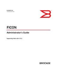
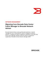
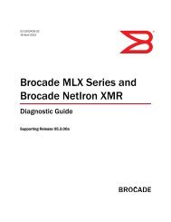
Chapter 1: Building the FoundationStorage-Centric vs. Network-Centric SANArchitecturesA SAN architecture is characterized by the relationship between serversand storage that is enabled by the fabric topology of switches anddirectors. A storage-centric architecture places storage assets at thecore of the SAN design with all fabric connectivity devoted to facilitatingaccess to storage LUNs by any attached server. A network-centricarchitecture, by contrast, borrows from conventional LAN networkingand promotes any-to-any peer connectivity. The impact of eachapproach becomes clear when we look at practical examples of SANdesigns in flat, mesh, and core-edge variations.Flat SAN TopologiesThe flat SAN topology has been a popular starting point <strong>for</strong> SAN designbecause it simplifies connectivity and can accommodate redundantpathing configurations <strong>for</strong> high availability. As illustrated in Figure 1,initiators (servers) and targets (storage arrays) are directly connectedto fabric switches or directors, and there is no need <strong>for</strong> inter-switchlinks (ISLs) to create data paths between switches and directors.Figure 1. A simplified flat SAN architecture with no ISLs4 <strong>Strategies</strong> <strong>for</strong> <strong>Data</strong> <strong>Protection</strong>
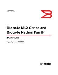
Storage-Centric vs. Network-Centric SAN ArchitecturesThis is a storage-centric design in that storage connectivity is centralizedto the fabric, and servers (with proper zoning) can attach to anystorage LUN. With redundant A and B pathing, storage transactionscan survive the loss of any single HBA, link, switch port, switch element,or storage port. Because each switch element providesindependent paths to each storage array, there is no need <strong>for</strong> ISLs toroute traffic between switches.Depending on the traffic load generated by each server, the fan-inratio of servers to storage ports (also known as “oversubscription”)can be increased. Typically, <strong>for</strong> 1 Gbit/sec links, a fan-in ratio of 7:1can be used, although that ratio can be increased to 12:1 at 2 Gbit/sec and 18:1 or greater at 4 Gbit/sec. In the example in Figure 1, theoversubscription would occur in the switch or director, with many moreports devoted to server attachment and fewer ports <strong>for</strong> storage connections.If the server fan-in ratio cannot accommodate the collectivetraffic load of each server group, however, congestion will occur at theswitch storage port and lead to a loss of per<strong>for</strong>mance and transactionstability.In practice, the flat SAN topology can be expanded by adding moreswitch elements, as shown in Figure 2.<strong>Strategies</strong> <strong>for</strong> <strong>Data</strong> <strong>Protection</strong> 5
Chapter 1: Building the FoundationFigure 2. Expanding a flat SAN architecture via the addition of switchelementsAlthough this design is entirely adequate <strong>for</strong> moderate-sized SANs, itbecomes difficult to scale beyond about 600 ports. Three 256-portdirectors on each A and B side, <strong>for</strong> example, would provide 768 ports<strong>for</strong> direct server and storage connections. Adding a fourth or fifthdirector to each side, however, would increase costs, complicate thecable plant, and increase the complexity of the SAN and itsmanagement.In addition, the flat SAN topology is perhaps too egalitarian in applyingan equal cost to all server connectivity regardless of the traffic requirementsof different applications. Particularly <strong>for</strong> flat SANs based onFibre Channel directors, high-usage servers may benefit from dedicated4 Gbit/sec connections, but that bandwidth and director realestate are squandered on low-usage servers. Likewise, a flat SANtopology cannot accommodate variations in cost and per<strong>for</strong>manceattributes of different classes of storage devices, and so offers thesame connectivity cost to high-end arrays and lower-cost JBODs (just a6 <strong>Strategies</strong> <strong>for</strong> <strong>Data</strong> <strong>Protection</strong>
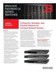
Storage-Centric vs. Network-Centric SAN Architecturesbunch of disks) alike. Consequently, even medium-sized SANs withvarying server requirements and classes of storage are better servedby a more hierarchical core-edge SAN design.Mesh SAN TopologiesIn conventional local area networks (LANs) and wide area networks(WANs), the network is composed of multiple switches and routerswired in a mesh topology. With multiple links connecting groups ofswitches and routers and routing protocols to determine optimumpaths through the network, the network can withstand an outage of anindividual link or switch and still deliver data from source to destination.This network-centric approach assumes that all connected enddevices are peers and that the role of the network is simply to provideany-to-any connectivity between peer devices.Figure 3. A mesh SAN topology with redundant pathing<strong>Strategies</strong> <strong>for</strong> <strong>Data</strong> <strong>Protection</strong> 7
Chapter 1: Building the FoundationIn a SAN environment, a mesh topology provides any-to-any connectivityby using inter-switch links between each switch or director in thefabric, as shown in Figure 3. As more device ports are required, additionalswitches and their requisite ISLs are connected. Because eachswitch has a route to every other switch, the mesh configuration offersmultiple data paths in the event of congestion or failure of a link, portor switch. The trade-off <strong>for</strong> achieving high availability in the fabric, however,is the consumption of switch ports <strong>for</strong> ISLs and increasedcomplexity of the fabric cable plant.Mesh topologies are inherently difficult to scale and manage as thenumber of linked switches increases. A mesh topology with 8 switches,<strong>for</strong> example, would require 28 ISLs (56 if 2 links are used per ISL). Asthe switch count goes higher, a disproportionate number of ports mustbe devoted to building a more complex and expensive fabric. Consequently,as a best practice recommendation, mesh topologies <strong>for</strong> SANsshould be limited to 4 switches.A more fundamental problem with mesh topologies, though, is theassumption that storage networks need any-to-any connectivitybetween peers. Although this model may be valid <strong>for</strong> messaging networks,it does not map directly to storage relationships. SAN enddevices can be active participants (initiators) or passive participants(targets). Initiators do not typically communicate with one another aspeers across the SAN, but with storage targets in a master/slave relationship.Storage arrays, <strong>for</strong> example, do not initiate sessions withservers, but passively wait <strong>for</strong> servers to instigate transactions withthem. The placement of storage targets on the SAN, then, should be tooptimize accessibility of targets by initiators and not to provide universal,any-to-any connectivity. This goal is more readily achieved with acore-edge design.8 <strong>Strategies</strong> <strong>for</strong> <strong>Data</strong> <strong>Protection</strong>
Storage-Centric vs. Network-Centric SAN ArchitecturesCore-Edge SAN TopologiesCore-edge SAN topologies enable a storage-centric, scalable infrastructurethat avoids the complexities of mesh topologies and limitedcapacity of flat SAN topologies. The core of the fabric is typically providedby one or more director-class switches which provide centralizedconnectivity to storage. The edge of the fabric is composed of fabricswitches or directors with ISL connections to the core.Figure 4. A core-edge SAN topology with classes of storage andserversAs shown in Figure 4, the heavy lifting of storage transactions is supportedby the core director since it is the focal point <strong>for</strong> all storageconnections, while the edge switches provide fan-in <strong>for</strong> multiple serversto core resources. This design allows <strong>for</strong> connectivity of differentclasses of servers on paths that best meet the bandwidth requirementsof different applications. Bandwidth-intensive servers, <strong>for</strong><strong>Strategies</strong> <strong>for</strong> <strong>Data</strong> <strong>Protection</strong> 9
Chapter 1: Building the Foundationexample, can be connected as core hosts with dedicated 4 Gbit/seclinks to the core director. Standard production servers can share bandwidththrough edge switches via ISLs to the core, and second-tierservers can be aggregated through lower-cost edge switches or iSCSIgateways to the core.Storage placement in a core-edge topology is a balance between manageabilityand application requirements. Placing all storage assets onthe core, <strong>for</strong> example, simplifies management and assignment ofLUNs to diverse application servers. Some departmental applications,however, could be serviced by grouping servers and local storage onthe same switch, while still maintaining access to core assets. An engineeringdepartment, <strong>for</strong> example, may have sufficient data volumesand high-per<strong>for</strong>mance requirements to justify local storage <strong>for</strong> departmentalneeds, in addition to a requirement to access centralizedstorage resources. The drawback <strong>for</strong> departmental-base storage isthat dispersed storage capacity may not be efficiently utilized. Consequently,most large data centers implement centralized storage tomaximize utilization and reduce overall costs.Figure 5. A three-tier core-edge SAN topology with the core servicingISLs to fabricAs shown in Figure 5, a three-tier, core-edge design inserts a distributionlayer between the core and edge. In this example, the core is usedto connect departmental or application-centric distribution switch elementsvia high-per<strong>for</strong>mance ISLs. <strong>Brocade</strong>, <strong>for</strong> example, offers 10Gbit/sec ISLs as well as ISL Trunking to provide a very high-per<strong>for</strong>-10 <strong>Strategies</strong> <strong>for</strong> <strong>Data</strong> <strong>Protection</strong>
Storage-Centric vs. Network-Centric SAN Architecturesmance backbone at the core. This tiered approach preserves theability to assign storage LUNs to any server, while facilitating expansionof the fabric to support additional storage capacity and serverconnections.For simplicity, the figures shown above do not detail alternate or dualpathing between servers, switches, and storage. The fabric illustratedin Figure 4, <strong>for</strong> example, could be the A side of a dual-path configuration.If directors are used, however, the full redundancy and 99.999percent availability characteristic of enterprise-class switches provideanother means to implement dual pathing. A server with dual HBAscould have one link connected to a director port on one blade, and aredundant link connected to a director port on a different blade. Likewise,storage connections can be provided from storage ports todifferent blades on the same director chassis. As in Fabric A and B,this configuration provides failover in the event of loss of an HBA, link,port, blade, or storage port.Inter-Fabric RoutingFibre Channel is a link layer (Layer 2) protocol. When two or more FibreChannel switches are connected to <strong>for</strong>m a fabric, the switches engagein a fabric-building process to ensure that there are no duplicateaddresses in the flat network address space. The fabric shortest pathfirst (FSPF) protocol is used to define optimum paths between the fabricswitches. In addition, the switches exchange Simple Name Server(SNS) data, so that targets on one switch can be identified by initiatorsattached to other switches. Zoning is used to en<strong>for</strong>ce segregation ofdevices, so that only authorized initiators can access designated targets.Analogous to bridged Ethernet LANs, a fabric is a subnet with asingle address space, which grows in population as more switches anddevices are added.At some point, however, a single flat network may encounter problemswith stability, per<strong>for</strong>mance, and manageability if the network grows toolarge. When a fabric reaches an optimum size, it is time to begin buildinga separate fabric instead of pushing a single fabric beyond itslimits. The concept of a manageable unit of SAN is a useful tool <strong>for</strong>determining the maximum number of switches and devices that willhave predictable behavior and per<strong>for</strong>mance and can be reasonablymaintained in a single fabric.<strong>Strategies</strong> <strong>for</strong> <strong>Data</strong> <strong>Protection</strong> 11
Chapter 1: Building the FoundationEnterprise data centers may have multiple large fabrics or SAN “continents.”Previously, it was not possible to provide connectivity betweenseparate SANs without merging SANs into a single fabric via ISLs. Withinter-fabric routing (IFR), it is now possible to share assets among multiplemanageable units of SANs without creating a single unwieldyfabric. As shown in Figure 6, IFR SAN routers provide both connectivityand fault isolation among separate SANs. In this example, a server onSAN A can access a storage array on SAN B via the SAN router. Fromthe perspective of the server, the storage array is a local resource onSAN A. The SAN router per<strong>for</strong>ms Network Address Translation (NAT) toproxy the appearance of the storage array and to con<strong>for</strong>m to theaddress space of each SAN. Because each SAN is autonomous, fabricreconfigurations or Registered State Change Notification (RSCN)broadcasts on one SAN do not impact the others.Figure 6. Using inter-fabric routing to provide device connectivitybetween separate SANsIFR thus provides the ability to build very large data center storageinfrastructures, the “data center fabric,” while keeping each fabric amanageable SAN unit. In combination with Fibre Channel over IP(FCIP), IFR can be used to scale enterprise-wide storage transportacross multiple geographies to further streamline storage operationswithout merging the remote fabrics over WAN networks.12 <strong>Strategies</strong> <strong>for</strong> <strong>Data</strong> <strong>Protection</strong>
Storage-Centric vs. Network-Centric SAN ArchitecturesVirtual FabricsIt is also possible to segregate departmental or business unit applicationson a shared SAN infrastructure by dividing the physical fabric intomultiple logical fabrics. Each virtual fabric (VF) behaves as a separateautonomous fabric with its own SNS and RSCN broadcast domain,even if the virtual fabric spans multiple fabric switches, as shown inFigure 7. To isolate frame routing between the virtual fabrics on thesame physical ISL, VF tagging headers are applied to the appropriateframes as they are issued, and the headers are removed by the switchbe<strong>for</strong>e they are sent on to the designated initiator or target. Theoretically,the VF tagging header would allow <strong>for</strong> 4,096 virtual fabrics in asingle physical fabric configuration, although in practice only a few aretypically used.Virtual fabrics are a means to consolidate SAN assets, while reducingmanagement complexity to en<strong>for</strong>ce manageable SAN units. In theexample shown in Figure 7, each of the three virtual fabrics could beadministered by a separate department with different storage, security,and bill-back policies. Although the total SAN configuration can bequite large, the division into separately-managed Virtual Fabrics simplifiesadministration, while leveraging the data center investment in SANtechnology.<strong>Strategies</strong> <strong>for</strong> <strong>Data</strong> <strong>Protection</strong> 13
Chapter 1: Building the FoundationFigure 7. Sharing a common SAN infrastructure via virtual fabricsAdditional SAN Design ConsiderationsWhether you are implementing a SAN <strong>for</strong> the first time or expanding anexisting SAN infrastructure, the one unavoidable constant in data storageis growth. The steady growth in storage capacity needs, inadditional servers and applications and in data protection requirements,is so predictable that anticipated growth must be an integralpart of any SAN design and investment. A current requirement <strong>for</strong> 50attached servers and 4 storage arrays, <strong>for</strong> example, could be satisfiedwith two 32-port switches (4 <strong>for</strong> redundant pathing) or a 256-portdirector chassis populated with two 32-port blades (4 <strong>for</strong> redundancy).14 <strong>Strategies</strong> <strong>for</strong> <strong>Data</strong> <strong>Protection</strong>
Storage-Centric vs. Network-Centric SAN ArchitecturesWhich solution is better depends on the projected growth in both storagecapacity and server attachment, as well as availability needs.Un<strong>for</strong>tunately, some customers have inherited complex meshed SANtopologies due to the spontaneous acquisition of switches to satisfygrowing port requirements. At some point, fabric consolidation may berequired to simplify cabling and management and to provide stability<strong>for</strong> storage operations. Without a solid foundation of a well-designedmanaged unit of SAN, higher-level data protection solutions are alwaysat risk.A managed unit of SAN can also be characterized by its intended functionality;and functionality, in turn, can drive a specific SAN topology. Ahigh-availability SAN, <strong>for</strong> example, requires redundancy in switch elementsand pathing, as well as management tools to monitor anden<strong>for</strong>ce continuous operation. However, a SAN designed <strong>for</strong> secondtierapplications may not justify full redundancy and be adequatelysupported on a more streamlined topology. In addition, a SANdesigned specifically <strong>for</strong> tape backup has very different requirementscompared to a production SAN. Tape is characterized by large block,bandwidth-intensive transactions, while production disk access is typicallydistinguished by small block and I/O-intensive transactions.Because tape operations consume bandwidth <strong>for</strong> extended periods oftime and are sensitive to fabric events, customers can implement twoseparate SANs or leverage Virtual Fabrics to isolate production diskaccess from backup operations. As a separate tape SAN, a flat SANtopology that avoids potential ISL oversubscription is recommended.An optimized SAN topology can also be affected by the server technologyused to host applications. Blade servers and blade SAN switches,in particular, can adversely impact the consumption of switchaddresses, or Domain IDs, and limit the total number of switchesallowable in a SAN unit. A new standard <strong>for</strong> N_Port ID Virtualization(NPIV) has been created to address this problem. An NPIV-enabledgateway presents logical hosts to the SAN and thus eliminates theaddition of another switch element, Domain ID assignment, andinteroperability or switch management issue. <strong>Brocade</strong> Access Gateway,<strong>for</strong> example, leverages NPIV to bring blade servers into the SANwithout requiring administrative overhead to monitor Domain ID usageand potential interoperability conflicts. As long as the edge SANswitches are NPIV aware, larger populations of blade servers can beaccommodated without limiting the scalability of the SAN topology.<strong>Strategies</strong> <strong>for</strong> <strong>Data</strong> <strong>Protection</strong> 15
Chapter 1: Building the FoundationHighly Available Storage<strong>Data</strong> protection solutions are dependent on a stable underlying SANtransport that is both predictable and manageable. The most carefullycrafted SAN, however, cannot ensure the availability and integrity ofdata if storage targets are vulnerable to data loss or corruption. Forenterprise-class applications in particular, storage systems must bedesigned to provide per<strong>for</strong>mance, capacity, data integrity, and highavailability. There<strong>for</strong>e, storage array architectures can include resiliencyfeatures to maximize availability of the array itself and to protectagainst data loss due to failed disk components.Local Mirroring (RAID 1)Spinning disk technology is mechanical and will eventually wear outand fail. As one of the first storage solutions to guard against disk failureand data loss, simple mirroring of data between two different disksor disk sets is easy to deploy, but it doubles the cost per data blockstored. Mirroring is also known as “RAID 1" and was one of the firstdata protection solutions at the disk level. As shown in Figure 8, diskmirroring can be implemented within a single array enclosure. In thetop example, data is written once by the server to the storage array.The array controller assumes responsibility <strong>for</strong> mirroring and so writesthe data to both primary and secondary mirror disk sets. If, however,data corruption occurs in the controller logic, the data integrity of theprimary and/or mirror may be compromised.In the bottom example in Figure 8, the volume manager running on theserver is responsible <strong>for</strong> mirroring and writes the data twice: once tothe primary and once to the secondary mirror. In both examples, if adisk failure occurs on the primary disk set, either the volume manageror the array controller logic must execute a failover from primary to themirror to redirect I/O and maintain continuity of data operations.16 <strong>Strategies</strong> <strong>for</strong> <strong>Data</strong> <strong>Protection</strong>
Highly Available StorageFigure 8. Array-based (top) and server-based (bottom) disk mirroringAlthough simple mirroring accomplishes the goal of protecting dataagainst disk failure, additional utilities are required to reconstitute theprimary disk set and re-establish the mirror operation. Once the failedprimary has been serviced, <strong>for</strong> example, the data on the primary mustbe rebuilt and synchronized to the new production mirror. For arraybasedmirroring, this is typically per<strong>for</strong>med as an automatic backgroundoperation and once synchronization has been achieved, theprimary is reinstated. This automated process, however, can haveunintended consequences. In one customer case study, a service callto replace a drive on a mirror inadvertently resulted in a drive on theprimary being swapped. Instead of failing over to the mirror image, themirror was rebuilt to the now-corrupted primary image. It is no greatmystery that tape backup endures as a data protection insurance policyagainst potential array failures.The primary drawback to mirroring within an array is that the entirearray is subject to failure or outage. Consequently, data centers mayphysically isolate primary and mirror arrays, placing them in separateareas with separate power sources.<strong>Strategies</strong> <strong>for</strong> <strong>Data</strong> <strong>Protection</strong> 17
Chapter 1: Building the FoundationFigure 9. Array-based mirroring between separate enclosuresAs illustrated in Figure 9, separating production and mirror arrays providesprotection against loss of disks, the array controller, and thearray enclosure. The mirroring function can be provided by the arraycontroller or the server. For switches that implement application services,the mirroring intelligence may be provided by the fabric itself. Insome vendor offerings, the mirroring operation can be bidirectional sothat two storage arrays can mutually act as mirrors <strong>for</strong> each other. Thishelps to reduce the overall cost and avoids dedicating an entire storagearray as a mirror.As a data protection element, mirroring offers the advantage of nearzerorecovery time and immediate recovery point. Given that storagesystems are the most expensive components of a storage network,however, mirroring comes at a price. In addition, unless mirroring iscombined with data striping across disks, it may lack the per<strong>for</strong>mancerequired <strong>for</strong> high volume data center applications.Other RAID LevelsIn addition to mirroring, data protection at the array can be en<strong>for</strong>ced byalternate RAID algorithms. RAID 0+1, <strong>for</strong> example, combines datastriping (RAID 0) with mirroring to enhance per<strong>for</strong>mance and availability.In RAID 0+1, data is first striped across multiple disks and thosedisks in turn are mirrored to a second set of disks. RAID 0+1 boostsper<strong>for</strong>mance, but it retains the additional cost of redundant arrays18 <strong>Strategies</strong> <strong>for</strong> <strong>Data</strong> <strong>Protection</strong>
Highly Available Storagecharacteristic of RAID 1. The inverse of RAID 0+1 is RAID 10, in whichcase the mirroring occurs first as a virtual disk be<strong>for</strong>e striping isexecuted.Other RAID techniques attempt to integrate the per<strong>for</strong>mance advantageof data striping with alternative means to reconstruct data in theevent of disk failure. The most commonly deployed is RAID 5, whichstripes data across a disk set and uses block parity instead of mirroringto rebuild data. As data blocks are striped across multiple disks, aparity block is calculated using an eXclusive OR (XOR) algorithm andwritten to disk. If a disk fails, the data can be reconstructed on a newdisk from the parity blocks. In RAID 4, the parity blocks are written to asingle dedicated disk. This creates some vulnerability if the parity diskitself fails and incurs a write penalty, since every write must be parityprocessed on a single drive. RAID 5 reduces the write penalty by placingthe parity in<strong>for</strong>mation across multiple disks in the RAID set. As theparity data is generated, the array controller does not have to wait <strong>for</strong>the availability of a dedicated disk. As shown in Figure 10, RAID 5arrays typically house spare disks that can automatically be broughtonline and reconstructed in the event of disk failure. In this example, ifthe third disk in the set fails, the parity block on the fifth disk (P abcd)can be used to recreate both block C and the parity block (P efgh) <strong>for</strong>blocks E, F, G, and H.Figure 10. RAID 5 with distributed parity blocksThe primary benefit of RAID 5 is its ability to protect block data whileminimizing the number of disks required to guard against failure. Onthe other hand, the write penalty generated by parity calculation needshardware acceleration to improve per<strong>for</strong>mance and avoid an adverseimpact to upper-layer applications.<strong>Strategies</strong> <strong>for</strong> <strong>Data</strong> <strong>Protection</strong> 19
Chapter 1: Building the FoundationWith parity distributed across multiple disks, RAID 5 provides protectionagainst a single disk failure. RAID 6 offers additional protection byduplicating the parity blocks across different disks. With multiple copiesof the parity blocks distributed over more disks, RAID 6 canwithstand the failure of two disks and still rebuild disk images fromspares.In addition to standard RAID types, storage vendors may offer proprietaryRAID options to optimize per<strong>for</strong>mance and reliability. Becausethe RAID function occurs in the array enclosure, the fact that the particularRAID level is proprietary or open systems has no practicalinteroperability implication. The only requirement is that the disks in aRAID set are of the same technology (Fibre Channel, SATA, or SAS) andhave equivalent capacity and per<strong>for</strong>mance characteristics.RAID as a Form of Storage VirtualizationJust as a volume manager on a server presents a logical view of storagecapacity that can exist on separate physical disks, a RAIDcontroller hides the complexity of multiple disks and the back-endRAID execution. Binding to a LUN on a RAID array, a server simply seesa single disk resource <strong>for</strong> reading and writing data. This abstractionfrom the physical to logical views places an immense responsibility onthe RAID controller logic <strong>for</strong> maintaining the integrity of data on theRAID set(s) and automatically recovering from back-end faults.Today's storage virtualization takes the logical abstraction of physicalassets to a new level. Instead of simply masking the appearance ofphysical disks in an enclosure, storage virtualization masks theappearance of entire RAID arrays. Creating a single logical pool of separatephysical storage systems facilitates capacity utilization anddynamic assignment of storage to upper-layer applications. As withbasic RAID, however, this places significant responsibility on the virtualizationengine to map the logical location of data to its actualphysical distribution across multiple arrays. Every successive level ofabstraction that simplifies and automates storage administration mustbe accompanied by a robust data protection mechanism workingbehind the scenes.Alternate Pathing and FailoverHigh-availability storage must provide both internal mechanisms <strong>for</strong>data redundancy and data integrity via RAID, in addition to continuousaccessibility by external clients. This requires the appropriate SANdesign as outlined in “Storage-Centric vs. Network-Centric SAN Architectures”on page 4 to build dual pathing through the fabric and multiportconnectivity on the array <strong>for</strong> each server. As illustrated in20 <strong>Strategies</strong> <strong>for</strong> <strong>Data</strong> <strong>Protection</strong>
Highly Available StorageFigure 11, alternate pathing can be configured as Fabrics A and B,which provide each server with a primary and secondary path to storageassets.Figure 11. Providing alternate paths from servers to storageIn this example, the failure of a storage port on the array or any link orport through Fabric A would still allow access through Fabric B. Withboth sides active in normal operation, though, each individual serversees two separate images of the same storage target: one from the Aside and one from the B side. A mechanism is there<strong>for</strong>e required toreconcile this side effect of dual pathing and present a single image ofstorage to the initiator. Typically, this reconciliation is per<strong>for</strong>med by adevice driver installed on the host. The driver may include the additionalability to load balance between alternate paths to maximizeutilization of all fabric connectivity.<strong>Strategies</strong> <strong>for</strong> <strong>Data</strong> <strong>Protection</strong> 21
Chapter 1: Building the FoundationAdditional High Availability Storage FeaturesHigh-end storage systems are further <strong>for</strong>tified with fault-tolerant featuresthat enable 99.999 percent availability. Redundantuninterruptible power supplies, redundant fans, hot-swappable diskdrives, redundant RAID controllers, and non-disruptive microcodeupdates guard against loss of data access due to any individual componentfailure. These high-availability features add to the complexityand total cost of the array, of course, and the selection of storage elementsshould there<strong>for</strong>e be balanced against the value of the databeing stored. The reality is that not all data merits first-class handlingthroughout its lifetime. Designing a SAN infrastructure with multipleclasses of storage containers provides more flexibility in migratingdata from one storage asset to another, and thus aligning the value ofstorage to the current business value of data.Storage and Fabric ConsolidationFor many data centers, the steady growth of data is reflected in thespontaneous acquisition of more servers, switches, and storagearrays. As this inventory grows, it becomes increasingly difficult tomanage connectivity and to provide safeguards <strong>for</strong> data access anddata integrity. In addition, the proliferation of storage arrays inevitablyleads to under-utilization of assets <strong>for</strong> some applications and over-utilization<strong>for</strong> others. To reduce the number of storage components andmaximize utilization of assets it may be necessary to re-architect theSAN on the basis of larger but few components.Storage and fabric consolidation are a means to streamline storageadministration and achieve a higher return on investment on SANinfrastructure. Previously, consolidation strategies were limited toreplacing dispersed assets with larger centralized ones. Today, theconcentration of resources can be further enhanced by new technologies<strong>for</strong> virtualizing the fabric (discussed in “Virtual Fabrics” onpage 13) and virtualizing storage capacity.As shown in Figure 12, a SAN that is the result of a reactive addition ofswitch and storage elements to accommodate growth quicklybecomes unmanageable. More switches means units to manage,more ISLs, complex cabling, longer convergence times, and greatervulnerability to fabric instability. While initially it may seem more economicalto simply connect an additional switch to support more ports,in the long run complexity incurs its own costs. Collapsing the SANinfrastructure into one or more directors or backbones simplifies managementand the cabling plant and promotes stability andpredictability of operation.22 <strong>Strategies</strong> <strong>for</strong> <strong>Data</strong> <strong>Protection</strong>
Storage and Fabric ConsolidationFigure 12. Simplifying the fabric and storage management viaconsolidationLikewise, reactively adding storage arrays to accommodate increasingcapacity requirements often leads to inefficient utilization of storageand increased management overhead. For the small SAN configurationillustrated here, storage consolidation requires an investment in alarger centralized storage system and data migration from dispersedassets to the consolidated array. For large data center SANs, servicingthousands of devices, the next step in storage consolidation may be tovirtualize designated storage systems to optimize capacity utilizationand facilitate data lifecycle management via different classes of virtualizedstorage.Storage and fabric consolidation projects can now take advantage ofenhanced features that streamline connectivity. Large storage arrays,<strong>for</strong> example, not only provide high availability and capacity but moreports <strong>for</strong> the SAN interconnect. Large arrays typically provide 128 to256 ports at 2, 4 or 8 Gbit/sec Fibre Channel speeds. <strong>Brocade</strong>'s introductionof 8 Gbit/sec support enables a much higher fan-in ratio ofclients per storage port. In addition, <strong>Brocade</strong> directors provide 8 Gbit/sec ISLs to both increase bandwidth <strong>for</strong> switch-to-switch traffic andsimplify cabling.Storage consolidation also includes technologies to centralize datageographically dispersed in remote sites and offices. As will be discussedin more detail in Chapter 7, centralizing data in the data centeris a prerequisite <strong>for</strong> safeguarding all corporate data assets, meeting<strong>Strategies</strong> <strong>for</strong> <strong>Data</strong> <strong>Protection</strong> 23
Chapter 1: Building the Foundationenterprise-wide regulatory compliance goals and reducing the cost ofIT support <strong>for</strong> remote locations. Implementing remote office data consolidationhas been contingent on the arrival of new technologies <strong>for</strong>accelerating data transactions over fairly low-speed WANs and innovativemeans to reduce protocol overhead and to efficiently monitor datachanges.SAN SecuritySecurity <strong>for</strong> storage area networks incorporates three primary aspects:• Secure data transport• Secure data placement• Secure management interfacesSecuring the data transport requires multiple levels of protection,including authorization of access, segregation of storage trafficstreams, maintaining the integrity of network (fabric) connectivity, andencryption/decryption of the data in flight across the SAN.Securing data placement must ensure that application data is writtento the appropriate storage area (LUN) in a specified storage system,that data copies are maintained via mirroring or point in time copy,and that sensitive data is encrypted as it is written to disk or tape.Securing the management interface must include means to validateauthorized access to SAN hardware, such as SAN switches and storagesystems, to prevent an intruder from reconfiguring networkconnections.These three components are interdependent and a failure to secureone may render the others inoperable. Safeguards can be implemented<strong>for</strong> data transport and placement, <strong>for</strong> example, but anexposed management interface can allow an intruder to redirect thestorage transport or deny access to data assets.24 <strong>Strategies</strong> <strong>for</strong> <strong>Data</strong> <strong>Protection</strong>
SAN SecuritySecuring the SAN <strong>Data</strong> TransportThe fact that the majority of SANs are based on Fibre Channel insteadof TCP/IP has created a false sense of security <strong>for</strong> data center storagenetworks. Hacking Fibre Channel data streams would require veryexpensive equipment and a high degree of expertise. In addition, thephysical security of data center environments is often assumed to providesufficient protection against malfeasance. As SAN technology hasbecome ubiquitous in data centers, however, no one should assumethat the SANs are inherently secure. Simply reconfiguring a server so itnow has access to designated storage assets could enable unauthorizedaccess to valuable corporate in<strong>for</strong>mation.Although Fibre Channel has relied on the physical separation of communicationnetworks and storage networks to provide a rudimentarysecurity barrier, modern business practices require a much higherassurance of data defense. Physical isolation alone does not providesecurity against internal attacks or inadvertent configuration errors.The storage industry has there<strong>for</strong>e responded with a spectrum ofsecurity capabilities to provide a high degree of data protection, whilestill maintaining the per<strong>for</strong>mance required <strong>for</strong> storage applications.ZoningAt a low level, zoning of resources in the SAN provides authorizedaccess between servers and storage ports through the Fibre Channelnetwork or fabric as illustrated in Figure 13. Zoning can be port based,restricting access by authorizing only designated Fibre Channel switchports and attached devices to communicate to each other. Alternately,zoning can be based on a 64-bit Fibre Channel World Wide Name(WWN). Since each Fibre Channel device has a unique WWN, it is possibleto authorize connections based on the unique identity of eachdevice.<strong>Strategies</strong> <strong>for</strong> <strong>Data</strong> <strong>Protection</strong> 25
Chapter 1: Building the FoundationFigure 13. Establishing zones between groups of initiators and targetsto segregate trafficPort-based zoning is fairly secure, since it cannot be spoofed by manipulatingframe headers. If a device is moved from port to port, however,the zone stays with the port, not the device. This makes hard or portbasedzoning more difficult to manage as adds, moves, and changesare made to the fabric. Soft zoning based on WWN provides the flexibilityto have zones follow the device itself, but can be spoofed ifsomeone inserts a valid WWN into a frame to redirect storage data.Zoning alone provides no means to monitor these sorts of intrusionsand has no integrated data encryption support.Port BindingPort binding established a fixed connection between a switch port andthe attached server or storage device. With port binding, only designateddevices are allowed on specified ports and a substitution ofdevices on a port results in port blocking of communications from thesubstituted end device, as shown in Figure 14.26 <strong>Strategies</strong> <strong>for</strong> <strong>Data</strong> <strong>Protection</strong>
SAN SecurityFigure 14. Creating secure device connectivity via port bindingPort binding thus locks in the authorized connection between the fabricand the device, ensuring that the link between the device and thefabric is secure. This mechanism prevents both deliberate and inadvertentchanges in connectivity that might allow an unauthorizedserver or workstation to gain access to storage data.Fabric BindingAt a higher level, it may also be desirable to secure connectionsbetween multiple fabric switches. Fibre Channel fabric switches aredesigned to automatically extend the fabric as new switches are introduced.When two fabric switches are connected via ISLs, theyautomatically exchange fabric-building protocols, zoning in<strong>for</strong>mation,and routing tables. While this is acceptable in some environments, itcreates a security concern. Someone wishing to probe the fabric couldsimply attach an additional switch and use it to gain entrance into theSAN.<strong>Strategies</strong> <strong>for</strong> <strong>Data</strong> <strong>Protection</strong> 27
Chapter 1: Building the FoundationFigure 15. Securing the fabric with fabric ISL bindingAs shown in Figure 15, fabric binding establishes fixed relationshipsbetween multiple switches in the network. Only authorized ISLs areallowed to communicate as a single fabric and any arbitrary attemptsto create new ISLs to new switches are blocked. Fabric bindingensures that established switch-to-switch connections are locked intoplace and that any changes to the SAN can occur only through secureadministrative control.Use of Inter-Fabric Routing to Secure the Storage NetworkAn additional layer <strong>for</strong> securing storage operations is provided by Inter-Fabric Routing technology. As discussed in “Inter-Fabric Routing” onpage 11, Inter-Fabric Routing can be applied in the data center to buildlarge, stable storage networks, or used <strong>for</strong> storage over distance applicationssuch as disaster recovery. In addition, Inter-Fabric Routing is ameans to block denial of service attacks if someone were to deliberatelyinitiate faults to cause disruptive fabric reconfigurations.SAN Routing technology prevents SAN-wide disruptions and reconfigurationsby providing fault isolation between fabric switches. Acting as arouter between SAN segments, the SAN router passes only authorizedstorage traffic between each attached SAN. Each SAN segment maintainsits autonomy from the others, and a disruption in one segment isnot allowed to propagate to other switches. Faults are there<strong>for</strong>e con-28 <strong>Strategies</strong> <strong>for</strong> <strong>Data</strong> <strong>Protection</strong>
SAN Securitytained at the segment level, and other fabric switches continue normaloperations. Denial of service attempts are restricted and not allowedto impact the entire storage network.SAN Routing products may support multi-vendor interoperability andbe extensible over any distance. For mission-critical data applicationssuch as disaster recovery, SAN Routing ensures that the underlyingtransport aligns with the customer's requirement <strong>for</strong> continuous, nondisruptivestorage operation.Virtual FabricsLarge data centers often support a wide variety of storage applications<strong>for</strong> different business units such as manufacturing, sales, marketing,engineering, and human resources. While it is possible to deploy aseparate physical fabric <strong>for</strong> each business unit, this solution adds significantcosts, reduces storage utilization and adds ongoingadministrative overhead. Storage administrators may there<strong>for</strong>eattempt to reduce costs by running multiple storage applicationsacross a larger unified SAN.In order to segregate storage traffic over a single large fabric and prevent,<strong>for</strong> example, sales applications from disrupting engineeringapplications, some means is needed to isolate the fabric resourcessupporting each application. For Fibre Channel SANs, this functionalityis provided by virtual fabric protocols. Frames <strong>for</strong> a specific applicationare tagged with identifiers that enable that application data to traverseits own path through the fabric. Consequently a large SAN switch withhundreds of ports can host multiple virtual fabrics (or virtual SANs).Similar to inter-fabric routing, disruptions or broadcast storms in onevirtual fabric are not allowed to propagate to other virtual fabrics.Security <strong>for</strong> IP SAN Transport via IEEE StandardsFor iSCSI and other IP-based storage protocols, conventional Ethernetstandards can be implemented to safeguard storage data transport.IEEE 802.1Q virtual LAN (VLAN) tagging, <strong>for</strong> example, can be used tocreate over 4,000 virtual LANs to separate traffic flows and ensurethat only members of the same VLAN can communicate. Like virtualfabrics in Fibre Channel, this mechanism enables multiple storageapplications to share the same infrastructure while gaining the protectionof segregated data streams. Access control lists (ACLs) commonlysupported in gigabit Ethernet switches and IP routers can be used torestrict access to only designated network devices.<strong>Strategies</strong> <strong>for</strong> <strong>Data</strong> <strong>Protection</strong> 29
Chapter 1: Building the FoundationIPSec <strong>for</strong> SAN TransportIP standards also provide a range of security features collectivelyknown as IPSec (IP security) standards. IPSec includes both authenticationand data encryption standards, and IPSec functionality iscurrently available from a community of IP network and securityvendors.For IP storage data in flight, data encryption can be implementedthrough conventional <strong>Data</strong> Encryption Standard (DES) or AdvancedEncryption Standard (AES). DES uses a 56-bit key, allowing <strong>for</strong> as manyas 72 quadrillion possible keys that could be applied to an IP datagram.The triple-DES algorithm passes the data payload through threeDES keys <strong>for</strong> even more thorough encryption. AES provides richerencryption capability through the use of encryption keys of 128 to 256bits.IPSec authentication and encryption technologies are integrated intothe iSCSI protocol and can be used in conjunction with storage overdistance applications, such as disaster recovery. Use of FCIP <strong>for</strong> storageextension over untrusted network WAN segments mandates dataencryption if data security is required.Although DES and AES were originally developed <strong>for</strong> IP networking, thesame key-based encryption technologies can be applied to payloadencryption of native Fibre Channel frames in SANs. With some vendorofferings, data may only be encrypted as it traverses the fabric anddecrypted be<strong>for</strong>e being written to disk or tape. In other products, thedata can remain in an encrypted state as it is written to disk anddecrypted only as it is retrieved by a server or workstation.30 <strong>Strategies</strong> <strong>for</strong> <strong>Data</strong> <strong>Protection</strong>
SAN SecuritySecuring Storage <strong>Data</strong> PlacementIn addition to securing storage data as it crosses the fabric betweeninitiator (server) and target (storage array), it may also be necessary tosecure storage data at rest. Safeguarding data at the storage systemhas two components. First, the application data must be written to itsspecified storage location in a storage array. The authorized relationship(binding) between a server application and its designated storagelocation ensures that an unauthorized server cannot inadvertently ordeliberately access the same storage data. Second, additional datasecurity can be provided by payload encryption as the data is written todisk or tape. Unauthorized access to or removal of disk drives or tapecartridges would thereby render the data unintelligible without theappropriate encryption keys.LUN MaskingLUN masking restricts access to storage resources by making visible toa server only those storage locations or logical units (LUNs) behind azoned storage port that a server is authorized to access. Both fabriczoning and LUN masking are needed to fully en<strong>for</strong>ce access controls.Zoning defines server to storage port access control while LUN maskingdefines which storage LUNs behind the storage port are availableto the server and its applications. If a large storage array, <strong>for</strong> example,supports 10 LUNs, a server may see only 1 available LUN. The other 9have been masked from view and are typically assigned to differentservers.<strong>Strategies</strong> <strong>for</strong> <strong>Data</strong> <strong>Protection</strong> 31
Chapter 1: Building the FoundationFigure 16. Restricting visibility of storage Logical Units via LUNmaskingLUN masking provides access control between storage assets andauthorized servers, preventing a server from inadvertently or deliberatelyattaching to unauthorized resources, as shown in Figure 16.Without LUN masking, a Windows server, <strong>for</strong> example, could query thefabric <strong>for</strong> available resources and attach to storage LUNs previouslyassigned to a Solaris server. Since Windows writes a disruptive signatureto its attached LUNs, this would render the Solaris dataunreadable. Although LUN masking can be implemented on an HBA atthe host, it is typically per<strong>for</strong>med on the storage array after initialconfiguration.32 <strong>Strategies</strong> <strong>for</strong> <strong>Data</strong> <strong>Protection</strong>
SAN SecurityiSCSI LUN MappingiSCSI LUN mapping is an additional technique to extend control of storageassets and create authorized connectivity across IP SANs. WithLUN mapping, the administrator can reassign LUNs to meet the storagerequirements of specific servers. A LUN 5 on the disk array, <strong>for</strong>example, can be represented as a LUN 0 to an iSCSI server, enabling itto boot from disk under tighter administrative control. Centralizedmanagement and iSCSI LUN mapping can ensure that servers loadonly their authorized system parameters and applications, and in combinationwith LUN masking, attach only to designated storageresources.Internet Simple Name Server (iSNS)The Internet Storage Name Service (iSNS) is an IETF-approved protocol<strong>for</strong> device discovery and management in iSCSI networks. iSNS combinesfeatures from Fibre Channel SNS with IP Domain Name Server(DNS) capability. As an integral part of the protocol definition, iSNSincludes support <strong>for</strong> public/private key exchange, so that storagetransactions in IP SANs can be authenticated and payload secured.iSNS has been endorsed by Microsoft and other vendors as the managementsolution of choice <strong>for</strong> iSCSI and IP storage environments.Encryption of <strong>Data</strong> at RestRecent publicity on the theft or loss of tape backup cartridge sets anddisk drives in large corporations highlights the inherent vulnerability ofremovable media. Retrieving storage data on tape or disk may requireexpensive equipment, but the proliferation of SAN technology has loweredthe threshold <strong>for</strong> this type of data theft. The highest level ofsecurity <strong>for</strong> storage data at rest is there<strong>for</strong>e provided by encryption ofdata as it is written to disk or tape. Previously, data encryption in theSAN imposed a significant per<strong>for</strong>mance penalty. With current SANsecurity technology, however, encrypting and decrypting data as itmoves to and from storage devices can be achieved with minimalimpact on production. As in any encryption solution, management ofencryption keys places an additional obligation on storageadministration.<strong>Strategies</strong> <strong>for</strong> <strong>Data</strong> <strong>Protection</strong> 33
Chapter 1: Building the FoundationSecuring the Management InterfaceManagement of a SAN infrastructure is typically per<strong>for</strong>med out of bandvia Ethernet and TCP/IP. A Fibre Channel fabric switch, <strong>for</strong> example,provides Fibre Channel ports <strong>for</strong> attachment to servers, storage systems,and other fabric switches (via ISLs), while also providing anEthernet port <strong>for</strong> configuration and diagnostics of the switch itself.Unauthorized access to the management port of a fabric switch isthere<strong>for</strong>e an extreme liability. Deliberate or inadvertent configurationchanges to a switch can result in unauthorized access to storageassets or loss of access altogether (also known as “denial of service”).In some implementations, fabric management is per<strong>for</strong>med in band,over the Fibre Channel infrastructure. This approach provides additionalprotection by making it more difficult <strong>for</strong> an intruder to tap intothe management data stream. However, if a Fibre Channel connectionis down, both production data and management data are blocked. Forlarge enterprises, redundant pathing through the fabric is used toensure that both production and management data have alternateroutes if a link failure occurs.Whether in band or out of band, ultimately an administrative interfacemust be provided at a console. As in mainstream data communications,it is there<strong>for</strong>e critical that the operator at that console hasauthorization to monitor fabric conditions or make configurationchanges. Standard management security mechanisms, such as CHAP(Challenge-Handshake Authentication Protocol), SSL (Sec)ure SocketsLayer), SSH (Secure Shell), and RADIUS (Remote Authentication Dial-InUser Service) are typically used to en<strong>for</strong>ce access authorization to thefabric and attached storage systems.34 <strong>Strategies</strong> <strong>for</strong> <strong>Data</strong> <strong>Protection</strong>
Going to the Next Level: The <strong>Brocade</strong> <strong>Data</strong> Center FabricGoing to the Next Level: The <strong>Brocade</strong> <strong>Data</strong> CenterFabricThe foundation elements of resilient storage systems and robust andsecure fabrics are prerequisites <strong>for</strong> implementing a coherent data protectionstrategy. The next phase in SAN evolution, however, mustextend the coverage of data to the upper-layer applications that generateand process data. This new application-centric approach isembodied by the <strong>Brocade</strong> data center fabric (DCF) architecture and itssupporting products, including the <strong>Brocade</strong> DCX Backbone, launchedin January 2008.The unique application focus of the <strong>Brocade</strong> DCF design aligns theentire storage infrastructure to the more dynamic requirements oftoday's business operations. For both server plat<strong>for</strong>ms and storage,rigid physical connections between applications and data are beingreplaced with more flexible virtual relationships and shared resourcepools. Enhanced data mobility, protection, and security are now key topreserving data integrity and fulfilling regulatory requirements. Bycombining enhanced connectivity with advanced storage and application-awareservices, the <strong>Brocade</strong> DCF is centrally positioned tocoordinate new capabilities in both server and storage plat<strong>for</strong>ms andmaximize data center productivity.To minimize disruption and cost, the <strong>Brocade</strong> DCF architecture, shownat a high level in Figure 17, is designed to interoperate with existingstorage and fabric elements while providing enhanced services whereneeded. The <strong>Brocade</strong> DCX Backbone, <strong>for</strong> example, integrates withexisting <strong>Brocade</strong> and third-party fabrics and extends their value by providingAdaptive Networking services, multi-protocol connectivity, datamigration services, storage virtualization, data encryption <strong>for</strong> data atrest, and other advanced services throughout the data center fabric.To simplify administration, these advanced services can be automatedvia policy-based rules that align to upper-layer applicationrequirements.<strong>Strategies</strong> <strong>for</strong> <strong>Data</strong> <strong>Protection</strong> 35
Chapter 1: Building the FoundationFigure 17. The <strong>Brocade</strong> DCF provides the infrastructure to optimizethe per<strong>for</strong>mance and availability of upper-layer business applications36 <strong>Strategies</strong> <strong>for</strong> <strong>Data</strong> <strong>Protection</strong>
Backup <strong>Strategies</strong>2Tape backup <strong>for</strong> data centers has been one of the original drivers <strong>for</strong>the creation of SAN technology. Be<strong>for</strong>e the advent of SANs, backing upopen systems storage data over 100 Mbit/sec Ethernet LANs was simplytoo slow and did not allow sufficient time to safeguard all dataassets. As the first gigabit network transport, Fibre Channel providedthe bandwidth and an alternate storage network infrastructure to offloadbackup operations from the LAN. Subsequently, the developmentof SCSI Extended Copy (third-party copy or TPC) technology also freedindividual servers from backup operations and enabled direct SANbasedbackup from disk to tape.Although obituaries <strong>for</strong> the demise of tape have been written repeatedlyover the past few years, tape endures as the principle mainstay ofdata protection. Unlike spinning disk media, once data is committed totape it can be transported offsite and vaulted, and has a reasonableshelf life. Even data centers that use newer disk-to-disk tape emulation<strong>for</strong> primary backup also often implement a final backup to tape.Conventional Local BackupTape backup operations and best practices date back to mainframeand midrange computing environments. Backup processes are thuswell defined <strong>for</strong> both proprietary and open systems applications, andtechnology innovation has largely focused on higher per<strong>for</strong>mance andgreater storage density of tape cartridge <strong>for</strong>mats and robotics. Evensecond-generation initiatives, such as virtual tape libraries (VTLs), relyon established practices honed over the years by conventional tapebackup operations.<strong>Strategies</strong> <strong>for</strong> <strong>Data</strong> <strong>Protection</strong> 37
Chapter 2: Backup <strong>Strategies</strong>Tape backup routines are shaped by an organization's recovery pointobjective (RPO) and recovery time objective (RTO). The recovery point,or the amount of data loss that can be tolerated in the event of datacorruption or outage, determines how frequently backups are executed.The recovery time objective is determined by how the backupsare per<strong>for</strong>med (incremental, differential, or full) and the severity of theoutage itself. A minor event, <strong>for</strong> example, may have a shorter recoverytime if an incremental backup can be used to restore data. A baremetal restore (<strong>for</strong> example, required when an entire storage arrayfails), by contrast, may have a much longer recovery time, since bothfull and incremental backups must be restored to rebuild the mostrecent data state.For many companies today the RPO <strong>for</strong> mission-critical applications isat or near zero. The loss of any data transaction is unacceptable. Fortape backup schedules that rely on daily incremental backups, then,additional utilities such as snapshots or continuous data protectionare required to protect against data loss that may occur between incrementalbackups. Not all data is essential <strong>for</strong> a company's survival,however, and the RPO can vary from one application to another. Periodictape backup on a daily basis is there<strong>for</strong>e the lowest commondenominator <strong>for</strong> safeguarding all data assets, while more advancedoptions should be implemented selectively <strong>for</strong> the highest-value data.In addition to RPO and RTO criteria, tape backup operations arebounded by the dimensions of the backup window, or the allowabletime to complete backups <strong>for</strong> all servers. Typically, applications mustbe quiesced so that files or records can be closed and in a static state<strong>for</strong> backup. For global or other 7/24 operation enterprises, however,there may be no opportunity to quiesce applications and thus nobackup window at all. Although backup software can be used <strong>for</strong> copyingopen files, the files themselves may change content as the backupoccurs.Conventional tape backup architectures <strong>for</strong> shared open systems environmentsare typically LAN-based, LAN-free (SAN-based), or server-free(SAN-based with Extended Copy). Although LAN-based backup configurationsare still common <strong>for</strong> small and medium-sized businesses,today's enterprise data centers normally per<strong>for</strong>m backup operationsacross a storage network.38 <strong>Strategies</strong> <strong>for</strong> <strong>Data</strong> <strong>Protection</strong>
Conventional Local BackupFigure 18. LAN-based tape backup transports both data and metadataover the LANAs shown in Figure 18 a LAN-based tape backup configurationrequires a backup server that acts as the repository <strong>for</strong> metadata(in<strong>for</strong>mation on the structure of files and which files or records havebeen copied) and the gatekeeper of the target tape subsystem.Although metadata may incur little overhead on the LAN, the continuousstreaming of gigabytes of data from the production server to thebackup server can seriously impact other LAN-based applications.Traditional LAN-based tape backup is based on backup of files. Eachserver on the LAN may have gigabytes of direct-attached storage thatneeds to be secured through backup. The backup server instructseach server to initiate a backup, with the data sent over the LAN fromserver to backup server. This type of backup involves multiple conversions.Upon launching a backup, the target server must read blocks ofSCSI data from disk, assemble the blocks into files, and packetize thefiles <strong>for</strong> transfer over the LAN. At the backup server, the inbound packetsmust be rebuilt into files, while the files are, in turn, disassembledinto blocks to be written to tape. The original data blocks that resideon the target storage there<strong>for</strong>e undergo four steps of conversionbe<strong>for</strong>e reappearing at the destination as blocks: blocks > file > packets> file > blocks. Both the server and backup server must devoteconsiderable Central Processing Unit (CPU) cycles to both SCSI andnetwork protocol overhead.<strong>Strategies</strong> <strong>for</strong> <strong>Data</strong> <strong>Protection</strong> 39
Chapter 2: Backup <strong>Strategies</strong>In addition, the limited bandwidth of the LAN (typically 1 Gbit/secEthernet) can impose a much longer backup window. Simply movingthe data path off the LAN and onto a higher per<strong>for</strong>mance storage networkcan alleviate the dual problem of LAN traffic load and backupwindow constraints. This was one of the initial issues that acceleratedthe adoption of SANs in enterprise data centers.Figure 19. LAN-free tape backup separates the metadata and datapaths to offload the LAN transport and optimize backup streamsacross the SANFigure 19 illustrates a LAN-free, SAN-based tape backup scheme. Inthis case, the target tape subsystem is deployed on the storage networkto create a more direct path between the production server andtape. As in LAN-based backup, the backup server is responsible <strong>for</strong>maintaining metadata on the backup process, but the productionserver can now request data from storage and copy it directly to thetape target. With the LAN transport no longer a bottleneck <strong>for</strong> streamsof backup data, the backup window becomes more manageable. Still,in both LAN-based and LAN-free solutions, the server remains in thedata path, reading data from storage and writing data to tape.40 <strong>Strategies</strong> <strong>for</strong> <strong>Data</strong> <strong>Protection</strong>
Conventional Local BackupFigure 20. Server-free backup removes the production server from thedata path, freeing CPU cycles <strong>for</strong> applications instead of backupoperationsServer-free backup takes a more direct path between storage and tapeby eliminating the production server from the backup process. Asshown in Figure 20 an extended copy engine in the SAN assumes bothinitiator and target roles on behalf of the server to per<strong>for</strong>m the readsand writes of data <strong>for</strong> the backup operation. The extended copy enginecan be resident in a SAN director or switch, an appliance attached tothe SAN, or embedded in the tape subsystem. The backup server isstill required to host metadata and monitor backup status, but themetadata path can now be across the SAN or via a LAN-attachedextended copy controller.While the high-per<strong>for</strong>mance SAN infrastructure and advanced utilities,such as extended copy, facilitate efficient backup of storage data, theapplication software that initiates and manages backup processes variesin capabilities from vendor to vendor. Although every storageadministrator recognizes the necessity of data backup, it is sometimesdifficult to verify that a backup operation was completed and that thetapes can actually be used to restore data. In addition, regular backupoperations may repeatedly copy data that is unchanged over time,which adds to the volume and duration of the backup process. Vendorsof backup software may provide additional utilities <strong>for</strong>verification, point-in-time (snapshot) backup <strong>for</strong> active databases,changed-block-only backup, data de-duplication, or other value-added<strong>Strategies</strong> <strong>for</strong> <strong>Data</strong> <strong>Protection</strong> 41
Chapter 2: Backup <strong>Strategies</strong>backup services. As the volume of storage data grows, the task ofsecurely backing up data in a reasonable time frame is increasinglydifficult.Backup Fabrics<strong>Data</strong> traffic on a production SAN is typically characterized by high I/Oof fairly short transactions. With the exception of streaming video orlarge image data applications (<strong>for</strong> example, medical or geophysicalimaging), the brevity of normal business transactions across a SANmakes those transactions more tolerant of transient fabric issuessuch as congestion or disruption. Tape backup, by contrast, is characterizedby the continuous streaming of blocks of data from the initiatorto the tape target. Any fabric disruption in the backup stream canabort the entire backup operation. <strong>Data</strong> centers can there<strong>for</strong>e elect tobuild a separate and dedicated fabric <strong>for</strong> tape backup, both to minimizedisruption to the backup process and to offload the tape trafficfrom the production SAN.Figure 21. A dedicated tape SAN isolates the backup process from theproduction SANAs shown in Figure 21, a dedicated tape SAN can be implemented inparallel with the production SAN to isolate backup traffic from otherstorage transactions. Because most Fibre Channel-to-SCSI bridges <strong>for</strong>tape attachment were originally based on Fibre Channel ArbitratedLoop (FCAL) protocol, the tape SAN would employ FCAL-capableswitches and FCAL HBAs <strong>for</strong> server attachment. Today, Fibre Channelports are typically integrated into tape subsystems and thus eliminatethe need <strong>for</strong> bridge products. Although implementing a separate tape42 <strong>Strategies</strong> <strong>for</strong> <strong>Data</strong> <strong>Protection</strong>
Conventional Local BackupSAN may require additional hardware and management, it doesenhance stability of tape operations to ensure backup completion.While <strong>Brocade</strong> enterprise-class plat<strong>for</strong>ms are commonly used <strong>for</strong> productionSAN connectivity, <strong>Brocade</strong> SAN switches, such as the <strong>Brocade</strong>5000 Switch, are often used to build dedicated tape backup SANinfrastructures.Disk-to-Disk (D2D) Tape EmulationOne of the persistent complaints made against tape backup stemsfrom the disparity between disk array speeds and tape speeds. Diskmedia simply spins at much higher rates than tape media, makingtape the inevitable bottleneck in the backup process. In addition, tapebackup is a linear process that is protracted by the constant repositioningof the tape media to the read/write head. The “shoe shine”motion of tape is essential <strong>for</strong> accurately positioning the tape media tomark the beginning of a backup stream, but necessarily incurs latency(as well as wear on the media itself).Figure 22. Disk-to-disk tape emulation requires no changes to backupsoftware<strong>Strategies</strong> <strong>for</strong> <strong>Data</strong> <strong>Protection</strong> 43
Chapter 2: Backup <strong>Strategies</strong>Because tape backup processes and software are so ubiquitous indata centers, it has been difficult to replace tape backup with an alternativetechnology. Consequently, vendors have developed tapeemulation products that enable disk arrays to behave as conventionaltape targets. In addition, some tape emulation devices can assumethe personality of different types of tape subsystems and so enable asingle emulation device to service multiple tape backup solutions.Because disk-to-disk tape emulation eliminates the bottleneck posedby tape mechanics, it is possible to dramatically reduce backup windows.<strong>Data</strong> retrieval from D2D is also expedited <strong>for</strong> either partial or fulldata restorations. As shown in Figure 22, disk-to-disk tape emulationcan be configured with an external appliance or be embedded in aspecialized disk array controller. From the standpoint of the backupapplication, the target device appears as a conventional tape subsystem.This makes it possible to drop in a D2D solution with no majorchanges to backup operations.Disk-to-Disk-to-Tape (D2D2T)Not all customers are com<strong>for</strong>table, however, with committing theirbackup data entirely to spinning media. Consequently, a disk-to-disktape emulation installation may be supplemented by a conventionaltape subsystem <strong>for</strong> long-term data archiving, as shown in Figure 23.Once data is backed up to the D2D array, it can be spooled to thedownstream tape subsystem and cartridges can be shipped offsite <strong>for</strong>safekeeping. In this case, the tape device no longer imposes a bottleneckto the backup process, since the initial backup has already beenexecuted to disk. D2D2T does not eliminate tape, but helps overcomethe limitations of tape in terms of per<strong>for</strong>mance <strong>for</strong> both backup andrestore of data. With ever-increasing volumes of data to safeguard viabackup and with regulatory compliance pressures on both data preservationand retrieval, D2D2T provides a means to both expediteprocesses and ensure long-term data protection.44 <strong>Strategies</strong> <strong>for</strong> <strong>Data</strong> <strong>Protection</strong>
Remote BackupFigure 23. Combining disk-to-disk tape emulation with conventionaltape backupRemote BackupBy leveraging storage networking, large enterprise data centers cancentralize backup operations <strong>for</strong> local storage systems and replacemultiple dispersed tape devices with larger, higher-per<strong>for</strong>mance tapesilos. In addition to the main data center, large enterprises may alsohave several smaller satellite data centers or regional offices with theirown storage and backup systems. Gaining control over all enterprisedata assets is difficult when backup processes can vary from oneremote location to another and when verifying the integrity of remotelyexecuted backups is not possible. The trend towards data center consolidationis there<strong>for</strong>e expanding to remote facilities, so that atminimum corporate data can be centrally managed and safeguarded.Previously, the limitations of WAN bandwidth excluded the possibilityof centralizing storage data backup operations from remote locationsto the main data center. Today, the combination of readily availablebandwidth and new storage technologies to optimize block data transportover WANs enables the centralization of tape backup operationsthroughout the enterprise.<strong>Strategies</strong> <strong>for</strong> <strong>Data</strong> <strong>Protection</strong> 45
Chapter 2: Backup <strong>Strategies</strong>Figure 24. Consolidating remote tape backup places all data underthe control and best practices of the data centerAs shown in Figure 24, remote sites can now leverage dark fiber,Dense Wave Division Multiplexing (DWDM), SONET, IP, or other WANtransports and protocols to direct backup streams to the central datacenter. SAN routers such as the <strong>Brocade</strong> 7500E, <strong>Brocade</strong> EdgeM3000, and <strong>Brocade</strong> USD-X, as well as the FR4-18i Extension Blade<strong>for</strong> the <strong>Brocade</strong> 48000 Director and <strong>Brocade</strong> DCX Backbone, providehigh-per<strong>for</strong>mance storage connectivity over WANs and optimize blockdata transport <strong>for</strong> backup and other storage applications.Consolidating backup operations to the main data center enables customersto extend data center best practices to all corporate data,including verification of scheduled backups and restorability of tapesets. If the primary data center implements disk-to-disk or D2D2Ttechnology, accelerated backup and data retrieval are likewiseextended to remotely generated data assets. In addition, the offloadingof backup operations to the data center reduces the requirement<strong>for</strong> remote support personnel, remote tape hardware, and remote tapehandling and offsite transport.46 <strong>Strategies</strong> <strong>for</strong> <strong>Data</strong> <strong>Protection</strong>
Remote BackupTape VaultingThe introduction of WAN optimization technology <strong>for</strong> block storagedata and increased availability of WAN bandwidth offer additionalstrategies <strong>for</strong> data protection, including the shifting of all backup operationsto centralized tape backup facilities. In this case, even datacenter backup operations are offloaded--with the additional advantagethat even the failure of one or more data centers would still leave corporatedata accessible <strong>for</strong> restoration to a surviving data center orthird-party service.Figure 25. Tape vaulting centralizes all data backup to a secure locationdedicated to protecting all corporate dataAs illustrated in Figure 25, tape vaulting further centralizes data protectionby hosting all backup operations in a secure, typically hardenedremote facility. In the event of a catastrophic failure at one or moreproduction sites, the most recent backups can be restored from thetape vault to resume business operations. As with centralized tapebackup, tape vaulting can provide enhanced protection <strong>for</strong> all corporatedata and facilitate higher levels of security, such as encryption ofdata as it is being written to tape. Larger enterprises may implementtheir own tape vaulting sites, but third-party services by companiessuch as Iron Mountain are also available.<strong>Strategies</strong> <strong>for</strong> <strong>Data</strong> <strong>Protection</strong> 47
Chapter 2: Backup <strong>Strategies</strong>Tape PipeliningIn the remote tape backup examples above, the transmission latenciesassociated with long-distance networking were not factored in. Speedof light latency results in about 1 millisecond (ms) of latency per 100miles each way, or 2 ms <strong>for</strong> the round trip. Depending on the quality ofthe wide area network service, additional latencies incurred by networkrouters may be significant. As will be discussed in more detail inChapter 3, “Disaster Recovery,” transmission latency over long distanceshas a direct impact on storage applications and in particular ontape backup. Although nothing can be done about the speed of light(other than quantum tunneling, perhaps), <strong>Brocade</strong> has addressed theproblem posed by latency <strong>for</strong> remote tape backup by introducing tapepipelining technology.Tape pipelining is used in the <strong>Brocade</strong> USD-X and Edge M3000 toexpedite the delivery of tape backup streams over very long distances.Without tape pipelining, every tape I/O must wait <strong>for</strong> acknowledgementfrom the receiving end be<strong>for</strong>e the next I/O can be executed.Figure 26. Without tape pipelining, per<strong>for</strong>mance falls dramatically duringthe first 10 miles.As shown in Figure 26, unassisted tape backup over distance slowsdramatically over the first few miles as both the transmission andacknowledgement encounter longer latencies. Tape pipeliningresolves this problem by providing local acknowledgement to tape I/Os. The <strong>Brocade</strong> USD-X and Edge M3000 buffer the I/Os issued by thelocal backup server, provide immediate acknowledgments <strong>for</strong> eachone, and then stream the backup data across the WAN link. At thereceiving end, they buffer the received data and spool it to the tapecontroller. Because neither storage router empties its buffers until thetarget tape device acknowledges that the data has been received, atemporary disruption in the WAN link will not result in loss of data orabort of the tape backup session.48 <strong>Strategies</strong> <strong>for</strong> <strong>Data</strong> <strong>Protection</strong>
Remote BackupTape pipelining is the enabling technology <strong>for</strong> enterprise-wide consolidatedtape backup and remote tape vaulting <strong>for</strong> both open systemsand FICON (Fiber Connectivity). It is currently supported on a wide varietyof WAN interfaces, including SONET, dark fiber, DWDM, ATM,Ethernet, and IP networks. In combination with IP networking, in particular,tape pipelining offers an economical means to span thousands ofmiles <strong>for</strong> centralized backup. Companies that were previously limitedto metropolitan distances can now place their data protection andarchiving sites in safe havens far from potential natural or socialdisruptions.<strong>Data</strong> Restoration from TapeThe elephant that is always in the room with tape backup is restorationof data from tape to disk in the event of a data corruption or data centerdisaster. No one wants to think about it and consequently manycompanies do not test the viability of their tape backup cartridges <strong>for</strong>restorability. As a result, tape backup is sometimes treated as a roteprocess driven by good intentions. It may mark the check box of regulatorycompliance, but without periodic testing cannot ensure dataprotection.Although the backup window is critical <strong>for</strong> committing all disk data totape, it is the restoration window that will determine the length of outageand the loss of revenue from lost business. The recovery timeobjective should there<strong>for</strong>e be realistically calculated on these basicvariables to the restoration process:• The total volume of data to be restored• The number of tape mounts required <strong>for</strong> that volume• The speed of the tape subsystem• The speed of the backup network• The configuration of the target disk arrayIf tape restore is per<strong>for</strong>med over Gigabit Ethernet, <strong>for</strong> example, a tapesubsystem capable of 140 Mbit/sec will encounter a bottleneck at the100 Mbit/sec limitation of the network. By contrast, a <strong>Brocade</strong> FibreChannel backup SAN can provide 2 Gbit/sec to 8 Gbit/sec throughputand support multiple tape restore streams concurrently.The design of a comprehensive and viable tape backup and restoresolution will determine whether data recovery takes hours, days, oreven weeks. Even the best design and implementation, however, isincomplete without periodic testing <strong>for</strong> restorability and resumption ofnormal business operations.<strong>Strategies</strong> <strong>for</strong> <strong>Data</strong> <strong>Protection</strong> 49
Chapter 2: Backup <strong>Strategies</strong>50 <strong>Strategies</strong> <strong>for</strong> <strong>Data</strong> <strong>Protection</strong>
Disaster Recovery3Disaster Recovery (DR) is often viewed as an insurance policy. No onelikes to pay the premiums but everyone fears the repercussions of notbeing covered. For today's enterprise data centers, Disaster Recoveryis virtually a mandatory requirement, if not <strong>for</strong> regulatory compliancethen <strong>for</strong> company survival. Whether downtime costs thousands or millionsof dollars per hour, a prolonged data outage leaves a companyvulnerable to competition, depreciation of brand, and loss of customers.One of the persistent challenges <strong>for</strong> IT administrations then is tocreate a workable disaster recovery plan that is always under constantpressure from budgetary constraints and the steady growth of datarequiring protection.Over the past decade storage networking technology has developed anew set of products and protocols that facilitate practical implementationof today's disaster recovery requirements. We are no longerbounded by distance or bandwidth restrictions and it is now possibleto deploy disaster recovery solutions that span thousands of miles.<strong>Brocade</strong> SAN Routers, <strong>for</strong> example, are supporting DR installationsthat link sites in Japan to recovery centers on the US east coast andothers that span the Atlantic from Europe to the US. These extremelylong-distance data protection solutions were unthinkable 10 yearsago. In addition, high per<strong>for</strong>mance DR is now possible <strong>for</strong> metro orregional sites. <strong>Brocade</strong> directors provide sufficient buffering to drive10 Gbit/sec per<strong>for</strong>mance <strong>for</strong> over 50 miles with maximum link utilization.Along with the technological innovations discussed below, thesenew capabilities are breaking the boundaries <strong>for</strong> implementing enterprise-wideDR solutions and give customers the flexibility to tailorsolutions to their own specific requirements.<strong>Strategies</strong> <strong>for</strong> <strong>Data</strong> <strong>Protection</strong> 51
Chapter 3: Disaster RecoveryDefining the Scope of Disaster Recovery PlanningIn terms of data storage, Disaster Recovery represents an essentialaspect of the much broader scope of business continuity. Businesscontinuity planning must include personnel, facilities, remote offices,power, transportation, telephone, and communications networks, inaddition to the data center infrastructure. The narrower scope of DRplanning focuses on data accessibility and so must consider servers,storage networks, and the data center physical plant. This includesproviding additional features, such as standby diesel power generatorsor redundant systems, to support a primary data center and provisioningdedicated recovery sites should the primary data center failcompletely.Disaster Recovery planning can be as streamlined as implementingperiodic tape backup and then relying on a service provider <strong>for</strong> datarecovery and access or as complex as designing <strong>for</strong> multiple levels ofdata protection at the primary data center and cloning the entire infrastructureat one or more recovery sites. <strong>Data</strong> centers represent such asubstantial investment, however, that duplicating servers, storageinfrastructure, cooling, and facilities <strong>for</strong> standby operation is difficult tojustify to non-IT upper management. Enterprises are there<strong>for</strong>e oftendual-purposing recovery sites <strong>for</strong> both DR and production or applicationdevelopment processing.As recent history has shown, both natural and man-made disastershave severe social and economic repercussions. No geographical locationis immune from potential disruption, but clearly some geographiesare more vulnerable than others. Coastal areas vulnerable to hurricanes,earthquakes, and tsunamis have an inherently higher riskfactor compared to inland areas, but even inland sites may be vulnerableto tornados or periodic flooding. Disaster Recovery planning shouldfactor in the inherent risk of a specific data center location and thatassessment in turn drives selection of appropriate technologies andsafe havens. A DR plan that uses Oakland as a recovery site <strong>for</strong> a datacenter in San Francisco, <strong>for</strong> example, probably does not adequatelyprotect against the potential effects of the San Andreas fault.How far does data have to travel to be safe? Prior to 9/11, companiesin Manhattan commonly relied on recovery sites in New Jersey. NewJersey itself suffered disruption, however, with the anthrax attacks themonth following the World Trade Center (WTC) attacks. During the cascadingNortheast power blackout in August, 2003, data centermanagers discovered that locating recovery sites hundreds of milesapart still cannot protect against severe failures of regional utilities.52 <strong>Strategies</strong> <strong>for</strong> <strong>Data</strong> <strong>Protection</strong>
Defining RTO and RPO <strong>for</strong> Each ApplicationA similar realization occurred in New Orleans in the fall of 2005, whencompanies whose recovery sites were in Houston were hit by both HurricanesKatrina and Rita within a month's time. Previously, theselection of a recovery site was limited by technology. It simply was notpossible to transport storage data beyond a metropolitan circumference.With current technologies now able to send storage datathousands of miles, companies can locate their recovery centers farfrom regional vulnerabilities.Defining RTO and RPO <strong>for</strong> Each ApplicationWhile all corporate data hopefully has some value, not all data needsto be instantly accessible <strong>for</strong> the immediate resumption of business incase of disaster or outage. One of the first steps in implementing aneffective Disaster Recovery strategy is to prioritize corporate data andapplications and match data types to levels of recovery. Online transactionprocessing, <strong>for</strong> example, may need a current and full copy ofdata available in the event of disruption. This requirement is generallymet through synchronous disk-to-disk data replication over a suitablysafe distance. For other data, by contrast, it may be sufficient to havetape backups available, with restoration to disk within two to threedays time. The Recovery Point Objective (the amount of data loss thatcould reasonably be accepted) and the Recovery Time Objective (theallowable time after an outage be<strong>for</strong>e business is seriously impacted)can both vary from one application to another. Sizing the recovery tacticto business requirements helps keep costs under control whilestreamlining a recovery process.The IBM user group SHARE (founded in 1955, the world's first organizationof computing professionals) has defined multiple tiers ofDisaster Recovery protection, ranging from no protection to continuousprotection and availability:Tier 0. No offsite data backupNo offsite data or means to recover from local disasterTier 1. <strong>Data</strong> backup with no hot siteOffsite backup with no recovery site (CTAM), or remote disk/tape butno remote processors/serversTier 2. <strong>Data</strong> backup with hot siteOffsite backup with bare metal recovery site (data must be reloadedand processors initialized)Tier 3. Electronic vaultingElectronic transmission of most current mission-critical data with taperestore <strong>for</strong> remainder<strong>Strategies</strong> <strong>for</strong> <strong>Data</strong> <strong>Protection</strong> 53
Chapter 3: Disaster RecoveryTier 4. Point-in-time copySnapshot copy of current volumes <strong>for</strong> streaming to remote diskTier 5. Transaction integrityApplication-dependent data consistency between the production andthe remote DR siteTier 6. Zero or little data lossAsynchronous or synchronous disk-to-disk copy with independent dataconsistencyTier 7. Highly automated, business-integrated solutionSynchronous disk-to-disk copy / automatic recovery of systems andapplicationsThe significance of this Disaster Recovery ranking is not that a companymust choose a single tier <strong>for</strong> all applications, but that differentapplications may merit different tiers. For example, a retail chain maybe able to sustain a lengthy data center outage <strong>for</strong> applications relatingto inventory or point-of-sale statistics. The individual stores, afterall, can continue to transact business, sell goods, and accumulateincome <strong>for</strong> weeks be<strong>for</strong>e shelf inventory becomes critical. A weekslongoutage of Microsoft Exchange, however, would be unacceptable,given that e-mail today is critical to the in<strong>for</strong>mation flow in all companies.In this example, Exchange would qualify <strong>for</strong> Tier 6 or 7 handling,while inventory applications might adequately be served by Tier 1 or 2solutions.Prioritizing business applications and data and then pairing differentapplications to different tiers of recovery are probably the most difficultbut essential steps in <strong>for</strong>mulating a cost-effective DR plan. If youasked individual business units if their data is critical to the survival ofthe company, of course, they would all say yes. An objective assessmentof the business value of application data is there<strong>for</strong>e required toboth contain costs and to ensure that truly mission-critical data getspriority during recovery. The alternative approach is to simply give allcorporate data equal value and priority, but this simpler solution isalso the most expensive. Synchronous data replication of inventoryprojection data or program development code can certainly be done(and storage vendors will gladly sell you the requisite additional storageand software licenses), but such data is better served bytraditional backup and offsite tape transport.54 <strong>Strategies</strong> <strong>for</strong> <strong>Data</strong> <strong>Protection</strong>
Synchronous <strong>Data</strong> ReplicationSynchronous <strong>Data</strong> ReplicationSynchronous data replication is often used <strong>for</strong> application data thatrequires a zero or near-zero recovery point objective. Typically implementedat the disk array controller, every write of data to disk isduplicated and sent to the (typically remote) secondary or recoveryarray. As shown in Figure 27, the local write complete status is notreturned to the initiating server until the secondary array has completedits write operation.Figure 27. Array-based synchronous replication over distanceBecause every transaction must be confirmed by the secondary storagearray, synchronous data replication provides an immediate RPOand RTO. In the event of a failure of the primary array or data center,operations can be immediately resumed at the recovery site with nodata loss. As the distance between primary and recovery sitesincreases, however, transmission latency can adversely impact serverper<strong>for</strong>mance. Synchronous data replication is there<strong>for</strong>e typicallyrestricted by the supplying vendor to about 150 miles or less. Forlonger distances, asynchronous replication can be used.Conventional array-based synchronous data replication is typically proprietaryand requires the same vendor products on both ends. Forcustomers who prefer a single vendor solution (or sometimes a “singleneck to choke”) this may not be an issue, but it does present a challengeto customers who have heterogeneous storage systems eitherthrough mergers and acquisitions or vendor changes over time. However,proprietary solutions are often accompanied by unique valueaddedservices optimized <strong>for</strong> the vendor's architecture.<strong>Strategies</strong> <strong>for</strong> <strong>Data</strong> <strong>Protection</strong> 55
Chapter 3: Disaster RecoveryFigure 28. Maximizing utilization of large storage systems <strong>for</strong> bi-directionalreplicationIn Figure 28, <strong>for</strong> example, the primary and secondary storage arrayscan be partitioned so that each array serves as the recovery system <strong>for</strong>the other. This active-active configuration enables the both primaryand secondary sites to function as full production centers and as zerodata-lossrecovery sites should either array or site fail.Metro DRGiven the distance limitations of synchronous data replication, it isnormally deployed within metropolitan environments. A financial institutionwith several sites in a city, <strong>for</strong> example, would implementsynchronous data replication to safeguard every data transaction,even though all of the sites are vulnerable to potential disruptionsinherent to that geography. The risk that one or all sites may fail simultaneously(<strong>for</strong> example, in the event of a major earthquake) must bebalanced against the likelihood of failures due to less disruptiveevents. The vast majority of data outages, after all, are due to operatorerror or the unintended consequences of upgrades or periodic servicecalls. As is discussed below, companies can implement a tiered DRplan that combines synchronous data replication as primary protectionwith asynchronous replication as a safeguard against true disasters.Today customers have a variety of options <strong>for</strong> Metropolitan Area Network(MAN) services to support synchronous data replication.Companies can install or lease dark fiber between primary and recoverysites and use DWDM or Course Wave56 <strong>Strategies</strong> <strong>for</strong> <strong>Data</strong> <strong>Protection</strong>
Synchronous <strong>Data</strong> ReplicationDivision Multiplexing (CWDM) to maximize utilization of the fiber opticcable plant. DWDM currently supports up to 64 channels on a singlefiber optic cable while CWDM, as the name implies, supports fewer at8 to 16 channels per fiber. Both DWDM and CWDM are protocol agnosticand so can support native Fibre Channel, Gigabit Ethernet, or IPover Ethernet. In combination with <strong>Brocade</strong> directors, switches andSAN Routers, DWDM/CWDM can easily accommodate metro storageapplications, including resource sharing and Disaster Recovery <strong>for</strong>both open systems and FICON.In many metropolitan areas, MAN service providers have built extensiveSynchronous Optical NETwork (SONET) rings around primarybusiness districts. Packet Over SONET (POS) enables encapsulation ofIP and so can be used <strong>for</strong> IP storage protocols, such as FCIP or iSCSI.In addition, some vendors provide interfaces <strong>for</strong> bringing native FibreChannel traffic into SONET.Figure 29. Leveraging metro SONET <strong>for</strong> native Fibre Channel disasterrecoveryAs shown in Figure 29, <strong>Brocade</strong> directors at both primary and recoverysites are Fibre Channel-attached to FC-SONET interfaces to connect tothe metropolitan SONET ring. With speeds from OC3 (155 Mbit/sec) toOC48 (2.5 Gbit/sec) SONET is a viable option <strong>for</strong> metro disaster recoverysolutions.Carriers are also providing Gigabit and 10 Gigabit Ethernet transports<strong>for</strong> metropolitan data applications. Metro Ethernet services are marketedprimarily <strong>for</strong> Internet broadband connectivity but can supportany IP traffic including FCIP <strong>for</strong> DR traffic. In the future, metropolitan10 Gigabit services will also be able to support Fibre Channel overEthernet (FCoE) once that protocol has achieved maturity.<strong>Strategies</strong> <strong>for</strong> <strong>Data</strong> <strong>Protection</strong> 57
Chapter 3: Disaster RecoveryLeveraging High Speed ISLsFor enterprise-class metropolitan DR applications, use of native FibreChannel Inter-Switch Links (ISLs) <strong>for</strong> connectivity between primary andrecovery sites eliminates the overhead of protocol conversion and simplifiesdeployment and management. A single ISL, however, may notbe sufficient to support the total volume of DR traffic, particularly ifdata replication <strong>for</strong> some applications is running concurrently withtape backup streams <strong>for</strong> other applications. To address this issue, <strong>Brocade</strong>has pioneered trunking technology that enables multiple ISLs tobe treated as a single logical ISL or trunk.Figure 30. Using <strong>Brocade</strong> trunking to build high per<strong>for</strong>mance metrodisaster recovery linksAs illustrated in Figure 30, up to eight 4 Gbit/sec ISLs can be combinedto create a single logical ISL capable of up to 32 Gbit/secthroughput. <strong>Brocade</strong> trunking maintains in-order delivery of frames toensure data reliability. Because all links are treated as a single logicalISL, the loss of a single ISL may reduce the total available bandwidthbut will not disrupt availability. Trunking is further enhanced with <strong>Brocade</strong>Dynamic Path Selection (DPS), which provides exchange-basedload balancing when multiple ISL trunks are configured between multipleswitches.The example shown in Figure 30 shows a maximum configuration butin practice two to four 4 or 8 Gbit/sec trunked ISLs would be sufficient<strong>for</strong> most metro DR applications. In addition, because each ISL is connectedto a different DWDM channel, the transmission length deltasbetween the channels must be considered. Typically a metro distanceof 50 miles or less is suitable <strong>for</strong> trunked ISLs over DWDM.<strong>Brocade</strong> has also introduced high-per<strong>for</strong>mance 10 Gbit/sec FibreChannel ISLs to further simplify the cabling scheme. The <strong>Brocade</strong> FC-10-6 blade, <strong>for</strong> example, supports six 10 Gbit/sec FC ports and up to<strong>for</strong>ty-eight 10 Gbit/sec ports can be configured in a single <strong>Brocade</strong>48000 Director chassis. As with all extension technologies, the bandwidth-to-distanceratio dictates that the higher the bandwidth, the58 <strong>Strategies</strong> <strong>for</strong> <strong>Data</strong> <strong>Protection</strong>
Asynchronous <strong>Data</strong> Replicationshorter the distance that can be supported. The 10 Gbit/sec FibreChannel port speed, however, is still adequate <strong>for</strong> most metro distances.If longer metro distances are required, trunked ISLs at lowerspeeds can be provisioned.Asynchronous <strong>Data</strong> ReplicationFor data replication beyond the 150-mile radius supported by synchronousapplications, asynchronous data replication can be used.Asynchronous data replication maintains optimum server per<strong>for</strong>manceby immediately issuing write complete status as soon as the data iscommitted to the local disk array. Multiple write operations are bufferedlocally and then sent en masse to the remote secondary array. Asshown in Figure 31, the remote array sends back its own write completesas they are executed. The primary array can then flush itsbuffers <strong>for</strong> the previous transactions and issue additional I/Os.Figure 31. Asynchronous data replication buffers multiple I/Os whileproviding immediate local acknowledgementAsynchronous data replication cannot guarantee a zero RPO if the primaryarray suffers a sudden failure. There is always the risk that oneor more transactions will be lost. For transitory WAN disruptions, however,most asynchronous schemes can resume operations by reissuingframes still held in the array buffers. In addition, if <strong>Brocade</strong>SAN Routers are used to provide WAN connectivity, they will also keepthe most recent transactions buffered until acknowledgment by thereceiving SAN router and this means that recovery of operations is initiatedindependent of the storage arrays.Asynchronous data replication can be array based, appliance based ordriven by a storage virtualization engine in a standalone product ordirector blade. Because asynchronous data replication is transparent<strong>Strategies</strong> <strong>for</strong> <strong>Data</strong> <strong>Protection</strong> 59
Chapter 3: Disaster Recoveryto server per<strong>for</strong>mance, it can drive over much longer latencies andsupport DR configurations spanning thousands of miles. Long-distanceWAN services are expensive, however, and the technicalchallenge <strong>for</strong> SAN extension <strong>for</strong> long haul DR is to optimize utilizationof the available bandwidth and get more data across in less time.Going the DistanceBandwidth and latency are distinct and unrelated variables. Bandwidthcan determine how much data can be issued across a link, buthas no effect on how long it takes to get to the other side. Latency isdetermined by transmission distance as well as intervening networkequipment and mitigating its effects requires other clever engineeringtechniques. Transaction latency over distance must account <strong>for</strong> bothtransmission of data and receipt of acknowledgment.Table 2. Transaction latency over distancePoint-to-PointDistance (km)Point-to-Pointdistance (mi)Latency eachway (ms)Round-triplatency (ms)893 555 5 101,786 1,110 10 202,679 1,664 15 303,572 2,219 20 404,465 2,774 25 505,357 3,329 30 606,250 3,884 35 707,143 4,439 40 80As shown in Table 2, transmission latency is about 1 millisecond (ms)per 100 miles or about 2 ms round trip. Because asynchronous transactionsare largely immune to latency, 80 ms or more round trip isacceptable. Still, if the latency of a certain distance is fixed by the lawsof nature and network equipment, it is always desirable to maximizethe amount of data that is delivered within the latency period.60 <strong>Strategies</strong> <strong>for</strong> <strong>Data</strong> <strong>Protection</strong>
Asynchronous <strong>Data</strong> Replication<strong>Brocade</strong> SAN extension products employ a number of innovations toreduce the negative impact of transmission latency on upper-layerapplications. Current <strong>Brocade</strong> SAN extension products leverage theavailability and longer reach of TCP/IP networks by encapsulatingFibre Channel in IP. FCIP and Internet Fibre Channel (iFCP) enable storagetraffic to take advantage of IP-based technologies such as jumboframes, data compression, and IP Security (IPSec) to both expeditedata delivery and secure storage data as it traverses the network. The<strong>Brocade</strong> enhancements discussed below include both IP-based andFibre Channel-based mechanisms that work in concert to optimize linkutilization and boost per<strong>for</strong>mance.Credit StarvationBecause the Fibre Channel architecture was originally designed <strong>for</strong>local data center application, support <strong>for</strong> long-distance deploymentwas never a priority. SAN connectivity is measured in feet or metersand only occasionally in miles or kilometers. Consequently, the standardswitch ports used <strong>for</strong> device attachment do not require largebuffers to accommodate long-distance transmission. The <strong>Brocade</strong>5000 Switch, <strong>for</strong> example, provides long-haul connectivity up to about25 miles at 4 Gbit/sec and about 50 miles at 2 Gbit/sec usingExtended Long-Wavelength Laser (ELWL) Small Form-factor Pluggable(SFP) optics. That makes it suitable <strong>for</strong> metro applications, but it is notdesigned to support transmissions of hundreds or thousands of miles.Without enhanced port buffering, a standard switch port transmits thecontents of its buffer and then waits <strong>for</strong> buffer credit renewal from itspartner at the other end of the WAN link, as shown at the top ofFigure 32. As the distance between the two switches is extended,more of the WAN link is idle while the initiator waits <strong>for</strong> credit replenishment.Additional idle time is incurred, however, when the receivingswitch send credits back to the initiator. This credit starvation resultsin wasted WAN bandwidth and further delays in data transmission atthe application layer.<strong>Strategies</strong> <strong>for</strong> <strong>Data</strong> <strong>Protection</strong> 61
Chapter 3: Disaster RecoveryFigure 32. Larger port buffers avoid credit starvationTo address this issue, <strong>Brocade</strong> SAN extension products such as the<strong>Brocade</strong> 7500E, 7500, and <strong>Brocade</strong> Edge M3000 SAN Routers, theFR4-18i Routing Blade, and the <strong>Brocade</strong> USD-X are designed withlarge port buffers to support long-distance SAN and DR applications.As shown at the bottom of Figure 32, enhanced port buffers enable<strong>Brocade</strong> SAN extension solutions to fill the WAN pipe with productivetraffic. As the receiving SAN router processes the data and hands it offto the downstream SAN, it can issue a steady stream of credits back toits partner as new data continues to arrive. Maximizing utilization ofthe WAN link both improves per<strong>for</strong>mance and the return on investment.The WAN provider, after all, charges <strong>for</strong> the link whether it isused efficiently or not.<strong>Data</strong> CompressionCompression technology identifies repetitive patterns in a data streamand represents the same in<strong>for</strong>mation in a more compact and efficientmanner. By compressing the data stream, more data can be sentacross the network, even if slower link speeds are used. At the destination,compressed data is returned to its original <strong>for</strong>m and deliveredintact to the receiving device. <strong>Brocade</strong> implements lossless compressionto ensure that the exact in<strong>for</strong>mation is reproduced from thecompressed data. Only the payload of a packet is compressed and notthe Transmission Control Protocol (TCP) header. Packets with sizesless than 512 bytes are not compressed.62 <strong>Strategies</strong> <strong>for</strong> <strong>Data</strong> <strong>Protection</strong>
Asynchronous <strong>Data</strong> ReplicationThe compression ratio compares the size of the original uncompresseddata to the compressed data. A compression ratio of 2:1, <strong>for</strong>example, means that the compressed data stream is half the size ofthe original data stream. There<strong>for</strong>e, by using data compression, a customerwould achieve twice the per<strong>for</strong>mance using the same networklinks.Compression is especially useful when transmitting storage data overa slow link such as a T1 (1.5 Mbit/sec) or 10 Mbit/sec Ethernet. Byenabling compression on a <strong>Brocade</strong> SAN router, a customer couldachieve 2 MB/sec data throughput on a T1 link and 11 MB/sec datathroughput on a standard 10 Mbit/sec Ethernet link. <strong>Data</strong> compressionthus enables use of slower, less expensive link speeds <strong>for</strong> suchstorage applications as asynchronous remote mirroring, remote tapebackup, and remote content distribution.<strong>Brocade</strong> data compression is recommended <strong>for</strong> use of T3 (45 Mbit/sec) and higher-speed WAN links. Without data compression, a T3 linkcan deliver approximately 4.6 MB/sec of storage data. With data compressionenabled, the T3 link can support 25 MB/sec of storage data,more than a fivefold increase in link utilization. Likewise, an OC-3 (155Mbit/sec) WAN link that would normally drive 16 MB/sec throughputcan, using compression, deliver 35 MB/sec throughput, a twofold gainin storage data throughput. Disaster Recovery implementations thattypically use T3 or higher speed WAN links can thus maximize use oftheir wide area services to safeguard more data more quickly.The efficiency of data compression depends on the data itself and thebandwidth of the WAN link. Not all data is compressible. Graphic andvideo data, <strong>for</strong> example, does not have the same data characteristicsas database records, which tend to have repetitive bit patterns. Inaddition, data compression is most efficient when there is a greaterdelta between ingress and egress speeds. The lower the WAN linkspeed, the more opportunity there is to examine the data held in theSAN router buffers and to apply the appropriate compression algorithmsif the data is compressible. If, <strong>for</strong> example, the ingress speed is1 Gbit/sec Fibre Channel and the egress is Gigabit Ethernet, it is moreexpeditious to simply hand the data to the WAN without compression.This explains why in the examples provided above, compression on aT3 link can enhance per<strong>for</strong>mance by a factor of 5:1, while compressionon a higher speed OC3 link is only a factor of 2:1.<strong>Strategies</strong> <strong>for</strong> <strong>Data</strong> <strong>Protection</strong> 63
Chapter 3: Disaster RecoveryJumbo FramesIn encapsulating Fibre Channel storage data in TCP/IP <strong>for</strong> transmissionover conventional WANs, it is necessary to address the disparitybetween Ethernet and Fibre Channel frame sizes. A typical Ethernetframe is 1518 bytes. A typical Fibre Channel frame is about 2112bytes. Wrapping Fibre Channel frames in Ethernet, there<strong>for</strong>e, requiressegmentation of frames on the sending side and reassembly on thereceiving side. This, in turn, incurs more processing overhead andundermines per<strong>for</strong>mance end to end.To align Fibre Channel and Ethernet frame sizes, a larger Ethernetframe is needed. Although not an official IEEE standard, a de factostandard called “jumbo frames” allows <strong>for</strong> Ethernet frames up toabout 9 k bytes in length. The caveat <strong>for</strong> use of jumbo frames is that allintervening Ethernet switches, network routers, and SAN routers mustsupport a common jumbo frame <strong>for</strong>mat.Use of a maximum jumbo frame size of 9 k bytes allows four FibreChannel frames to be encapsulated in a single Ethernet frame. Thiswould, however, complicate Fibre Channel link layer recovery as well asbuffer flow control. Instead, <strong>Brocade</strong> SAN routers encapsulate a completeFibre Channel frame into one jumbo Ethernet frame. BecauseFibre Channel frames may include extended and optional headers orvirtual fabric tagging in<strong>for</strong>mation, the jumbo Ethernet frame size is notfixed and varies depending on the requirements of the encapsulatedFibre Channel frame.Jumbo frames help expedite packet processing by increasing the payloadof every frame transmission and eliminating the continuousoverhead of segmentation and reassembly of Fibre Channel framesfrom smaller 1500-byte Ethernet frames. If all network equipmentbetween source and destination supported jumbo frames, this isanother option that provides incremental improvement of per<strong>for</strong>manceand link utilization.Rate LimitingThe TCP layer above IP is an end-to-end insurance policy against dataloss. Because the available bandwidth through a network may be variableand traffic loads unpredictable, congestion and buffer overruns inthe intervening network equipment can occur. In IP environments, theresponse to congestion is to simply throw away frames, a reaction thatis horrifying to storage administrators. Packets may be lost, but thanksto the TCP layer they will be recovered and retransmitted. Packetrecovery, however, has a per<strong>for</strong>mance penalty. The TCP layer must64 <strong>Strategies</strong> <strong>for</strong> <strong>Data</strong> <strong>Protection</strong>
Asynchronous <strong>Data</strong> Replicationidentify the missing packets and generate retransmission. The IP layer,in turn, does not simply resume at full speed but incrementally rampsup the transmission rate until congestion again occurs.Early adopters of SAN extension over IP soon learned of this behaviorwhen curious “sawtooth” per<strong>for</strong>mance patterns occurred. Levels ofreasonably high per<strong>for</strong>mance were periodically punctuated with suddendrops, as illustrated in the middle of Figure 33.Figure 33. Using <strong>Brocade</strong> rate limiting to avoid congestion and erraticper<strong>for</strong>manceThis constant cycle of congestion and recovery severely impacts per<strong>for</strong>manceand results in wasted bandwidth on the WAN link.As shown at the bottom of Figure 33, <strong>Brocade</strong> avoids the erraticbehavior caused by congestion, packet loss, recovery, and IP windowramping by pacing the load delivered to the WAN link. By restricting thetraffic offered to the WAN to the designated bandwidth (in this example,a T3 at 45 Mbit/sec), <strong>Brocade</strong> SAN routers can minimize potentialcongestion and recovery latencies and help ensure the uninterrupteddelivery of data that storage applications expect.<strong>Strategies</strong> <strong>for</strong> <strong>Data</strong> <strong>Protection</strong> 65
Chapter 3: Disaster RecoveryFastWriteThe SCSI protocol includes commands and status exchanges that facilitatemoving large blocks of data in an orderly fashion between serversand storage. When servers and storage are separated by distance,however, the normal SCSI exchange may lead to inefficient use of thebandwidth available in the WAN link. <strong>Brocade</strong> SAN routers incorporatea FastWrite option to address this problem. FastWrite preserves standards-basedSCSI protocol exchanges, while enabling full utilization ofthe available bandwidth across wide area connections and a 10x orgreater per<strong>for</strong>mance increase <strong>for</strong> storage applications.Pioneered by Nishan Systems in 2001, FastWrite is now an integralpart of <strong>Brocade</strong> SAN extension technology. In order to understand howFastWrite works, it is useful to review standard SCSCI write operationsas illustrated in Figure 34. There are two steps to a SCSI write. First,the write command is sent across the WAN to the target. The firstround trip is essentially asking permission of the storage array to senddata. The target responds with an acceptance (FCP_XFR_RDY). The initiatorwaits until it receives this response from the target be<strong>for</strong>estarting the second step, sending the data (FCP_DATA_OUT). For largeI/Os, the initiator sends multiple FCP_DATA_OUTs sequentially, butmust wait <strong>for</strong> an FCP_XFR_RDY <strong>for</strong> each one as shown in Figure 34.When all the data has finally been received by the target and committedto disk, the target responds with a write complete status(FCP_STATUS). In this example, the SAN routers are simply passingSCSI commands and data across the WAN between the initiator andthe target.As the distance and accompanying latency between the initiator andtarget increases, more and more transaction time is consumed bySCSI protocol overhead. This appears to be an inevitable result oftransmission latency over long WAN links and that would indeed be thecase if the SAN routers provided only protocol conversion betweenFibre Channel and IP. <strong>Brocade</strong> SAN routers, however, are intelligentdevices that can support more sophisticated applications and Fast-Write can behave as a proxy target to the initiator and a proxy initiatorto the real target.66 <strong>Strategies</strong> <strong>for</strong> <strong>Data</strong> <strong>Protection</strong>
Asynchronous <strong>Data</strong> ReplicationFigure 34. A standard SCSI write operation over distance requires significantprotocol overheadAs shown in Figure 34, when the initiator issues a write command tothe target (in this example <strong>for</strong> 1 MB of data), the local SAN router proxies<strong>for</strong> the remote target and immediately responds with a transferready <strong>for</strong> the entire amount to be written. As the initiator responds witha series of DATA_OUTs, the local SAN router buffers the write data andissues a FCP_CMD_WRT to its partner SAN router on the far side of theWAN link. After an acknowledgment from the remote SAN router, thelocal SAN router begins streaming the entire payload across the WANin a single write operation.At the receiving end, the remote SAN router proxies as an initiator tothe remote target and issues an FCP_CMD_WRT to it. The remote targetresponds with an XFR_RDY specifying the amount that can be sentwith each DATA_OUT. On both sides of the WAN link, the SCSI protocoloverhead functions normally but is localized to each side. When all thedata has finally been committed to the remote disk array, the targetresponds with a write complete FCP_STATUS, which is relayed by theSAN routers back to the initiator.<strong>Strategies</strong> <strong>for</strong> <strong>Data</strong> <strong>Protection</strong> 67
Chapter 3: Disaster RecoveryFigure 35. FastWrite dramatically reduces the protocol overheadacross the WAN link by proxying <strong>for</strong> both initiator and targetBecause there is no spoofing of the write complete, there is no riskthat the write operation will inadvertently be confirmed if a WAN disruptionoccurs during this process. For transient WAN outages, the<strong>Brocade</strong> SAN routers keeps TCP sessions active and resumes operationsonce the link is restored. In the event of a hard failure of the WANlink during the FastWrite operation, the sessions will terminate and theinitiator, having not received a write complete, will know the write wasunsuccessful. This ensures data integrity and safeguards the immortalsouls of SAN router design engineers. The prime directive of storagenetworking technology, after all, is to preserve the sanctity of customerdata.FastWrite has been used in customer deployments <strong>for</strong> over five yearsand has repeatedly demonstrated substantial per<strong>for</strong>mance improvements<strong>for</strong> Disaster Recovery and data migration applications.Customers have seen a 10x or better per<strong>for</strong>mance boost and havebeen able to compress data migration projects from weeks to days. Incombination with large port buffers, data compression, jumbo frames,and rate limiting, FastWrite enables <strong>Brocade</strong> SAN routers to deliverenterprise-class SAN extension that fully utilizes WAN bandwidth and68 <strong>Strategies</strong> <strong>for</strong> <strong>Data</strong> <strong>Protection</strong>
Asynchronous <strong>Data</strong> Replicationexpedites data delivery over long-haul DR installations. As detailed inTable 3, <strong>Brocade</strong> FastWrite provides sustained high per<strong>for</strong>mance overextremely long distances spanning thousands of miles.Table 3. Comparison of per<strong>for</strong>mance over long distances with andwithout FastWritemskmAverageThroughputmskmAverageThroughput0 0 55 0 0 551 200 37 1 200 552 400 30 2 400 555 1,000 18 5 1,000 5510 2,000 10 10 2,000 5515 3,000 7 15 3,000 5520 4,000 5.7 20 4,000 5525 5,000 5.01 25 5,000 5530 6,000 4.3 30 6,000 4335 7,000 3.5 35 7,000 4040 8,000 3.5 40 8,000 39IP Security (IPSec)<strong>Data</strong> moving over any link poses a potential security risk. The securitymechanisms discussed in Chapter 1 help secure the data center SANagainst internal and external intrusions as well as inadvertent disruptionsdue to operator error or system upgrades. Long-haul DR usingFCIP or iFCP protocols can also be secured through established IETFIPSec algorithms. The <strong>Brocade</strong> 7500 SAN router and FR4-18i ExtensionBlade, <strong>for</strong> example, provide hardware-based IPSec dataencryption <strong>for</strong> en<strong>for</strong>cing high-per<strong>for</strong>mance security over untrusted networksegments. In combination with the WAN optimization facilitiesdiscussed above, <strong>Brocade</strong>'s IPSec implementation ensures both thesecurity and expeditious delivery of storage data across the network.<strong>Strategies</strong> <strong>for</strong> <strong>Data</strong> <strong>Protection</strong> 69
Chapter 3: Disaster RecoveryDisaster Recovery TopologiesAlthough Disaster Recovery scenarios can use the common elementsof source, transport and destination, the profiles of practical DR configurationscan vary widely from one customer to another. A small ormedium enterprise, <strong>for</strong> example, can have a single disk array at its productionsite and per<strong>for</strong>m synchronous or asynchronous datareplication to a remote array. Large enterprises can have dozens ofarrays distributed over multiple data centers and replicate to one ormore strategically located DR facilities. In addition, remote data replicationmay be only one element of a more complex DR strategy,incorporating continuous data protection mechanisms and centralizedtape vaulting. Disaster recovery topologies are thus more streamlinedor more complex depending on the business requirements of theenterprise and the amount and variation of data types to be securedagainst loss.Three-Tier DRBecause synchronous data replication is bounded by WAN latency, it istypically deployed within a 150-mile radius from the primary data center.Synchronous replication has excellent RPO and RTOcharacteristics, but still cannot protect storage data if a region-widedisaster or outage occurs. Some enterprises there<strong>for</strong>e have moved toa three-tier DR model that incorporates both synchronous and asynchronousreplication schemes.70 <strong>Strategies</strong> <strong>for</strong> <strong>Data</strong> <strong>Protection</strong>
Disaster Recovery TopologiesFigure 36. A three-tier DR topology provides an extra layer of data protectionin the event of regional disruptionAs shown in Figure 36, conventional synchronous replication can beimplemented within a metropolitan circumference to provide recovery<strong>for</strong> a failure of the primary data center. This two-tier scenario is augmentedby an additional WAN link to provide asynchronous replicationto a third site. Because asynchronous replication is highly tolerant oflatency, the third remote recovery site can be situated thousands ofmiles from the primary data center and there<strong>for</strong>e well beyond thereach of a regional disruption. If a regional failure were to occur, thereis always the possibility that one or more transactions would be lost.This potential loss, however, is miniscule compared to the potentialdata loss if both primary and secondary sites were to failsimultaneously.Round Robin DRLarge enterprises with multiple data centers have yet another option toprovide data protection <strong>for</strong> all locations while minimizing costs. Asillustrated in Figure 37, a round-robin DR topology circumvents theneed to build a dedicated disaster recovery center by leveraging existingdata centers and WAN connectivity. Depending on the<strong>Strategies</strong> <strong>for</strong> <strong>Data</strong> <strong>Protection</strong> 71
Chapter 3: Disaster Recoverygeographical distribution of the data centers, each location can use itsdownstream neighbor as a data replication site, while also acting as arecovery site <strong>for</strong> an upstream neighbor.Figure 37. In a round-robin DR topology, each data center acts as therecovery site <strong>for</strong> its neighborThere are multiple variations on this theme. Two data centers in thesame metropolitan area, <strong>for</strong> example, could act as mutual synchronousreplication sites to each other, while both asynchronouslyreplicate to a more distant partner. In addition, all data centers couldimplement centralized tape vaulting as a safeguard against the failureof two or more data centers. In this example, if data centers B and Cfailed simultaneously, data center D could assume the work of C, andonly data center B's data would be inaccessible until restoration fromtape is completed.Be<strong>for</strong>e the advent of WAN optimization technologies and storage protocolsover IP, these types of topologies were cost prohibitive due tothe lease rates <strong>for</strong> WAN bandwidth. Today, however, more storage datacan be transported over less expensive WAN services and at muchlonger distances, making three-tier and round-robin configurations farmore af<strong>for</strong>dable.72 <strong>Strategies</strong> <strong>for</strong> <strong>Data</strong> <strong>Protection</strong>
SAN Routing <strong>for</strong> DRSAN Routing <strong>for</strong> DRAs we discussed in Chapter 1, Inter-Fabric Routing technology providesfault isolation when connecting two or more fabrics either locally orover distance. Also known as “SAN Routing,” IFR enables devices ondifferent fabrics to communicate but blocks potentially disruptive RegisteredState Change Notification (RSCN) broadcasts and fabricbuildingprotocols. SAN Routing is thus an ideal complement to DRover distance. The goal of Disaster Recovery, after all, is to providecontinuous or near-continuous access to storage data and SAN Routingcontributes to this goal by minimizing potential disruptions to fabricstability.Figure 38. SAN Routing rein<strong>for</strong>ces stability of the DR implementationby maintaining the autonomy of each site.As shown in Figure 38, <strong>Brocade</strong> SAN Routers provide connectivitybetween the resources that have been authorized to communicateacross the WAN link. Instead of merging both fabrics into a single SAN,SAN Routers maintain the autonomy of each fabric. A disruption in theDR fabric, <strong>for</strong> example, would not propagate to the production fabric aswould be the case if standard ISL links were used. In the exampleshown in Figures 37 and 38 above, SAN Routing is a prerequisite <strong>for</strong>connecting multiple sites over distance. Deploying a single extendedfabric across multiple locations simply poses too much risk and underminesthe central goal of Disaster Recovery.<strong>Strategies</strong> <strong>for</strong> <strong>Data</strong> <strong>Protection</strong> 73
Chapter 3: Disaster RecoveryDisaster Recovery <strong>for</strong> SMBsAlthough large enterprises have long recognized the necessity of acomprehensive DR plan, Small and Medium Businesses (SMBs) alsoappreciate the value of protecting their data assets from natural orman-made disruptions. Hurricane Katrina, <strong>for</strong> example, did not discriminateon the basis of gross annual receipts and impacted allbusinesses equally. The ability to recover and resume business operations,however, hinges on the level of preparedness and the ability toexecute against the DR plan.SMBs depend on their IT operations as much as any large, multinationalenterprise, albeit on a smaller scale. This smaller scale, however,works to the advantage of SMBs, because there is typically muchless data to secure and far simpler infrastructures to clone <strong>for</strong> DRsites. Large enterprises have essentially funded the research anddevelopment of SAN and DR technologies by being the early adoptersand largest clients <strong>for</strong> shared storage technology. Although, once thetechnology is proven and in production, costs typically decline, bringingmore sophisticated storage products into the price range of SMBs. The<strong>Brocade</strong> 7500E SAN Router, <strong>for</strong> example, incorporates WAN and protocoloptimization features designed to meet the demandingrequirements of large enterprises but is now an af<strong>for</strong>dable DR element<strong>for</strong> the tighter budgets of many SMBs. Likewise, <strong>Brocade</strong> switches and<strong>Brocade</strong> 8 Gbit/sec 815 and 825 Host Bus Adapters (HBAs) are economicalSAN building blocks that maintain enterprise-classfunctionality and per<strong>for</strong>mance <strong>for</strong> both production and DRapplications.Vendors of storage networking products offer tiered solutions thatmeet high-end, mid-range, and low-end requirements. A mid-rangestorage array, <strong>for</strong> example, can still provide enterprise-class RAID onthe front end but use more economical Serial ATA (SATA) or Serial SCSI(SAS) disks on the back end. The mid-tier systems also provide enterprise-classDR functionality, such as synchronous and asynchronousdisk-to-disk data replication, but at a lower cost than first-tier storagearrays. In addition, vendors may provide storage appliances which supportasynchronous replication between heterogeneous storage arrays,eliminating the need to pair production and DR arrays from a singlevendor.74 <strong>Strategies</strong> <strong>for</strong> <strong>Data</strong> <strong>Protection</strong>
Continuous <strong>Data</strong> <strong>Protection</strong>4The tape backup and data replication technologies discussed in theprevious chapters provide varying degrees of data protection andrecovery <strong>for</strong> standard business applications. These mechanismsalone, however, have proven inadequate <strong>for</strong> more demanding missioncriticalapplications. Synchronous data replication, <strong>for</strong> example, capturesevery transaction and allows resumption of operations with nodata loss. Synchronous data replication does not maintain a history ofthose transactions and cannot be used to restore operations to aknown “good” point in time if data corruption occurs. A virus attack onan e-mail server simply replicated to the recovery array. Consequently,a new class of data protection mechanisms is required <strong>for</strong> trackingchanges to data and enabling restoration from variable recoverypoints.Among its other tasks, the <strong>Data</strong> Management Forum (DMF) of the StorageNetworking Industry Association (SNIA) is defining a new set oftechnologies <strong>for</strong> continuous data protection (CDP). The DMF definesCDP as a “…methodology that continuously captures or tracks datamodifications and stores changes independent of the primary data,enabling recovery points from any point in the past.” The phrase “anypoint in the past” is figurative here, given that the CDP change historyitself takes additional storage capacity and that capacity is not infinite.CDP solutions can be block based, file based or application based.Compared to tape backup or data replication, CDP offers much finergranularity and the ability to move the recovery point objective selectivelybackward in time.<strong>Strategies</strong> <strong>for</strong> <strong>Data</strong> <strong>Protection</strong> 75
Chapter 4: Continuous <strong>Data</strong> <strong>Protection</strong>Defining the Scope of CDPTape backup and remote data replication provide protection againstthe loss of a storage array, a system outage, or loss of the entire datacenter. CDP, by contrast, is not primarily designed to recover from catastrophicphysical events but is focused on the more subtle risks posedby data corruption as transaction data is modified over time. CDPthere<strong>for</strong>e lies closer to the application layer, and in a large data center,multiple CDP instances may be running against multiple applicationsconcurrently.As shown in Figure 39, the recovery points <strong>for</strong> tape backup and datareplication are fixed in time. For tape, the recovery point is the lastincremental backup. For asynchronous data replication, the recoverypoint is the last completed write of buffered I/Os to the secondaryarray. For synchronous data replication, the recovery point is the lasttransaction written to both primary and secondary arrays, even if thattransaction wrote corrupted data. The recovery times are also fixed tothe extent that restoration from tape takes a set time depending onthe volume of data to be restored (hours or days), and both asynchronousand synchronous mechanisms require a cutover from primary tosecondary array access.Figure 39. Continuous data protection provides finer granularity <strong>for</strong>data restoration when corruption occurs.76 <strong>Strategies</strong> <strong>for</strong> <strong>Data</strong> <strong>Protection</strong>
Defining the Scope of CDPBecause true continuous data protection is driven by changes to datainstead of fixed points in time, the recovery point is variable. The frequencyof monitoring and logging data changes can differ from oneCDP solution to another but all CDP utilities provide a sliding recoverypoint that not only facilitates recovery but ensures the integrity of thedata once the application resumes.The data changes that CDP tracks on a primary array are stored on aseparate storage system, which is either co-located in the data centeror remote at a secondary or DR site. The amount of additional storagerequired by CDP is determined by the rate of data changes and the frequencyof monitoring those changes. Periodic monitoring based onsnapshot technology is known as “near CDP” and is described as “frequentmonitoring and change tracking but not actually continuous.”Near CDP is thus more accurately described as periodic data protection(PDP). True CDP, by contrast, continuously monitors and tracksdata changes and so is constantly updating the CDP store.<strong>Strategies</strong> <strong>for</strong> <strong>Data</strong> <strong>Protection</strong> 77
Chapter 4: Continuous <strong>Data</strong> <strong>Protection</strong>Near CDPNear CDP solutions may use a number of different snapshot or pointin-timecopy mechanisms to capture the state of a storage volume atany given moment. Snapshot-based near CDP triggers on a predefinedinterval to create a recovery point. If, <strong>for</strong> example, a snapshot is takenevery 10 minutes, the snapshots would contain 6 recovery points perhour. If data corruption is detected, the restore point would be 1 of the6 recovery points or possibly more, depending on the total number ofsnapshots allowed. A system allowing 40 revision points, <strong>for</strong> example,could accommodate recovery points up to 6 hours prior to detection ofdata corruption, but with granularity of only 10-minute intervals.Depending on the vendor implementation, some products provide <strong>for</strong>hundreds of recovery points. Once the designated number of recoverypoints has been reached, a rotation algorithm replaces the older snapshotswith new ones, as shown in Figure 40.Figure 40. Aged snapshots are rotated on a configurable interval toconserve disk space on the CDP store.True CDPTrue CDP (or simply, CDP) takes granularity to a finer level by monitoringand tracking every data change as it occurs. This eliminates thepossibility of losing transactions during a snapshot interval but itrequires a more sophisticated mechanism <strong>for</strong> accurately managingchange metadata. CDP can operate at the file or block level, and inboth cases triggers on the write (that is, change) of data to primarystorage. Copy-on-write, <strong>for</strong> example, copies an original data location tothe CDP store just prior to the new write execution. If the write to theprimary array contains corrupted data, there is still a copy of the originaldata on the CDP volume to restore from.78 <strong>Strategies</strong> <strong>for</strong> <strong>Data</strong> <strong>Protection</strong>
True CDPFigure 41. The CDP engine manages metadata on the location andtime stamp of data copies on the CDP store.To accurately track data changes, a CDP engine must maintain metadataon the location of copies and the time stamps used todifferentiate one revision from another, as shown in Figure 41. Agraphical interface is typically provided to simplify identification ofrecovery points via a slider or dial to roll back to a designated point intime. Block-based CDP is data-type agnostic and so can operateagainst structured, semi-structured, or unstructured data.At the application layer, however, it may be necessary to coordinateCDP metadata with the application to maintain data consistency. AnOracle or SQL Server transaction, <strong>for</strong> example, may issue multiplewrites to update a record. Restoring to a known good transaction staterequires coherence between what the application expects and the requisitecopies that CDP metadata can recover. Application-based CDP isthus tightly integrated with the application's specific file or recordrequirements via application programming interfaces (APIs) or as acomponent of the application itself.<strong>Strategies</strong> <strong>for</strong> <strong>Data</strong> <strong>Protection</strong> 79
Chapter 4: Continuous <strong>Data</strong> <strong>Protection</strong>Integrating CDP with Tape Backup and DisasterRecoveryAlthough there has been marketing-inspired confusion over “near” and“true” CDP, the technology has proven value <strong>for</strong> addressing issues thatsimple tape backup and data replication alone cannot resolve. Applicationor operator errors that result in data corruption, accidentaldeletion of files, or virus attacks on e-mail systems can bypass conventionaldata protection solutions. On the other hand, CDP alone isinsufficient to protect against system outages or disasters. Some vendorsare there<strong>for</strong>e combining CDP with traditional tape backup and DRto provide more comprehensive coverage <strong>for</strong> data assets.Snapshot recovery points, <strong>for</strong> example, can be used as static volumeimages <strong>for</strong> tape backup, leaving the production storage array free toservice ongoing transactions while the backup occurs. In addition, theCDP store and metadata manager can be located at a remote DR siteto protect against both data corruption and outage at the primary datacenter.80 <strong>Strategies</strong> <strong>for</strong> <strong>Data</strong> <strong>Protection</strong>
In<strong>for</strong>mation LifecycleManagement5The introduction of in<strong>for</strong>mation lifecycle management (ILM) technologiesover the past few years has marked the maturity of the networkedstorage infrastructure and its ascent toward the application layer. Priorto ILM, data was treated as having constant value that required uni<strong>for</strong>mtreatment until it was finally retired to a tape archive. Typicallythat uni<strong>for</strong>m treatment consisted of high-availability transport, robustfailover mechanisms, and high-end storage. As the volume of dataincreased over time, larger fabrics and additional storage arrays wererequired, often straining the capacity and the budget of the datacenter.The tendency to accommodate the growth of data via constant expansionof the storage infrastructure, however, is not sustainable as longas all data is weighted equally. There is simply not enough floor space,cooling plant, and power to contain growing data volumes and notenough budget to provide first-class handling <strong>for</strong> all application data.Fortunately, the reality is that not all application data is equal in value,and even a single data set may have varying value through its lifetime.In<strong>for</strong>mation lifecycle management translates this reality into a strategy<strong>for</strong> tracking the business value of data and migrating data from oneclass of storage to another, depending on the value of data at a givenpoint in time. Each class of storage represents a specific cost point interms of per<strong>for</strong>mance, availability, cost of storage per gigabyte, andassociated power costs. <strong>Data</strong> with high value gets first-class treatment,but as that value declines over time it is more efficient to movethe data to a more economical storage container.<strong>Strategies</strong> <strong>for</strong> <strong>Data</strong> <strong>Protection</strong> 81
Chapter 5: In<strong>for</strong>mation Lifecycle ManagementAn order entry, <strong>for</strong> example, has high value as long as it is tied to pendingrevenue. Once the order is assembled, shipped, and mostimportantly, billed, the transaction declines in value and may have onlyhistorical significance (<strong>for</strong> example, <strong>for</strong> data mining). However, if severalmonths later the customer places an identical order, the originaltransaction may regain value as a reference <strong>for</strong> the detail of the initialorder, customer in<strong>for</strong>mation, and so on. As shown in Figure 42, ILMcan migrate data from high-end to mid-tier and from mid-tier to aneven lower tier or tape, while still being able to promote the data to ahigher class when needed.One of the major challenges of ILM is to determine the current value ofa given data set. Using time stamps in file metadata is one approach.If data is rarely accessed, it is legitimate to assume it has less immediatevalue. Another method is to manipulate file metadata or createseparate metadata on block data to assign a priority or value ratingthat can be monitored and changed over time. A value-tracking mechanismis key, though, <strong>for</strong> automating the ILM process and avoidingoperator intervention to manually migrate data.Figure 42. Aligning cost of storage to business value of data82 <strong>Strategies</strong> <strong>for</strong> <strong>Data</strong> <strong>Protection</strong>
Tiered SAN ArchitecturesAlthough it would appear to be much simpler to deploy a single class ofstorage <strong>for</strong> all data, that is not feasible <strong>for</strong> large data centers withspace, power, cooling, and budget constraints. In addition, large datacenters may already have different classes of storage installed to serviceless-mission-critical applications. By reserving space on secondorthird-tier storage <strong>for</strong> ILM-migrated data, storage managers can freespace on their first-tier arrays and maximize utilization of their lowertiersystems.Tiered SAN ArchitecturesTiered SAN architectures are predicated on two basic conceptsclassesof storage and classes of storage transport-which reflect differentcost, availability, and per<strong>for</strong>mance points. To maximize thevalue of a storage infrastructure, both storage and the storage interconnect(or fabric) should be aligned. A JBOD, <strong>for</strong> example, is far moreeconomical than a high-end RAID array but typically lacks the highavailability, recoverability, and per<strong>for</strong>mance of top-tier systems. Consequently,fabric connectivity to a JBOD may not merit the higher speed,alternate pathing, and 99.999 percent availability provided by top-tierplat<strong>for</strong>ms, such as the <strong>Brocade</strong> DCX Backbone or <strong>Brocade</strong> 48000Director. In a core/edge SAN design, the JBOD is more appropriatelypositioned toward the edge on a more economical SAN switch. Aligningthe class of storage to the appropriate class of transport maximizesthe cost effectiveness of each tier without squandering capacity orbandwidth.Classes of Storage ContainersStorage systems are characterized by the front-end services they provideand back-end disk capacity and I/O per<strong>for</strong>mance. First-tier arrays,<strong>for</strong> example, offer multiple storage ports <strong>for</strong> SAN connectivity, configurableRAID levels, alternate pathing, large cache memory, andpossibly virtualization services on the front end and provide high-per<strong>for</strong>manceand high-capacity disks (typically Fibre Channel) on the backend. Second-tier systems may provide fewer SAN ports, fixed RAID levels,less caching, and alternate pathing on the front end and use lessexpensive SATA or SAS disks on the back end. A third-tier storage systemmay provide no caching or RAID controller logic and lowerper<strong>for</strong>manceback-end disks. In addition, some systems are deliberatelydesigned <strong>for</strong> lower-per<strong>for</strong>mance applications, such as MAID(massive array of idle disks) systems that expect infrequent I/O.<strong>Strategies</strong> <strong>for</strong> <strong>Data</strong> <strong>Protection</strong> 83
Chapter 5: In<strong>for</strong>mation Lifecycle ManagementClasses of storage can be classified in a hierarchy that spans a rangeof systems-from high-per<strong>for</strong>mance and high-availability to much lowerper<strong>for</strong>mancetape and optical storage:Class 1. High-availability, high-per<strong>for</strong>mance RAID systemsClass 2. Moderate-per<strong>for</strong>mance RAID systemsClass 3. Fibre Channel JBODsClass 4. Custom disk-to-disk-to-tape systemsClass 5. High- per<strong>for</strong>mance tape librariesClass 6. Moderate-per<strong>for</strong>mance tape subsystems and devicesClass 7. Optical jukeboxesEach tier or class of storage per<strong>for</strong>ms the basic function of storingdata, but with distinctly different levels of per<strong>for</strong>mance, availability,reliability, and (most importantly) cost. When ILM migrates data fromone class of spinning media to another, the underlying assumption isthat the data still has sufficient value that it needs to be accessible orreferenced on demand. Otherwise, the data eventually retires to thelower storage classes: tape or optical media. <strong>Data</strong> can be retrievedfrom tape, but because tape is a linear storage media, data retrieval isa much longer process.Classes of Storage TransportCorresponding to different classes of storage, the SAN transport canbe configured with different classes of bandwidth, security, and availabilitycharacteristics. As shown in Figure 43, the scalability of FibreChannel from 1 Gbit/sec to 10 Gbit/sec and iSCSI from 1 Gbit/sec tosubgigabit speeds enables the transport to align to different classes ofstorage and applications and thus optimize fabric resources.84 <strong>Strategies</strong> <strong>for</strong> <strong>Data</strong> <strong>Protection</strong>
Tiered SAN ArchitecturesFigure 43. Aligning classes of storage transport to classes of storageand applicationsIn this example, 8 and 10 Gbit/sec ISLs and future storage connectionsrepresent the top tier of the storage transport. For the <strong>Brocade</strong>DCX Backbone and <strong>Brocade</strong> 48000 Director, 8 and 10 Gbit/sec ISLscan be deployed in the data center to create a high-per<strong>for</strong>mance SANbackbone as well as extended to metropolitan distances. The 4 and 8Gbit/sec ports represent the next tier, with connectivity to high-endand/or mid-tier storage and high-per<strong>for</strong>mance servers. The 2 and 4Gbit/sec ports can support second-tier storage and servers and 1Gbit/sec Fibre Channel to drive legacy FC servers.The addition of iSCSI to the configuration provides more tiers of connectivity.When connected via <strong>Brocade</strong> iSCSI-to-FC ports, iSCSI candrive lower-tier iSCSI servers at 1 Gbit/sec Ethernet as well as subgigabitremote iSCSI servers across a campus or WAN link.<strong>Strategies</strong> <strong>for</strong> <strong>Data</strong> <strong>Protection</strong> 85
Chapter 5: In<strong>for</strong>mation Lifecycle ManagementIn addition to proportional bandwidth allocation, the storage infrastructurecan be configured to provide higher or lower levels ofavailability through dual- or single-path connectivity. When data hashigher value, accessibility is rein<strong>for</strong>ced by alternate pathing andfailover through the SAN. When its value declines and the data is lessfrequently accessed, single-path connectivity may be sufficient. Likewise,fabric security features can be judiciously allocated to morecritical storage assets depending on the level of security they merit.Aligning <strong>Data</strong> Value and <strong>Data</strong> <strong>Protection</strong>Ideally, the value of data should determine the level of data protectionthat is provided <strong>for</strong> it. This is difficult to achieve in single-tier systemsbecause there is no means to differentiate high-value data from lowvaluedata. In a tiered storage architecture, however, the class of storageitself defines the level of data protection. Top-tier storage mayrequire synchronous replication, snapshots, continuous data protection,or disk-to-disk-to-tape backup. For second- or third-tier storage,tape backup alone is probably sufficient.ILM surfaces another data protection issue, though. As data is agedand archived onto tape, the retention period may no longer be the conventional10 to 15 years that was previously assumed. In addition tobusiness data that may be subject to regulatory compliance and longtermretention requirements, the fact that today virtually all knowledgeis in digital <strong>for</strong>mat is raising concerns about much longer data protectionand retention. In surveys conducted by the Storage NetworkingIndustry Association's <strong>Data</strong> Management Forum, <strong>for</strong> example, 80 percentof respondents have in<strong>for</strong>mation retention requirements ofgreater than 50 years and 68 percent indicate that their data retentionrequirements were in excess of 100 years. This poses significant challengesnot only <strong>for</strong> durable long-term physical media but <strong>for</strong> logical<strong>for</strong>matting of data that can be read by applications of the future. Thefailure to migrate archived data to more current <strong>for</strong>mats and mediaperiodically could make today's enormous repository of in<strong>for</strong>mationinaccessible to future generations. John Webster, founder of the <strong>Data</strong>Mobility Group, has called this a potential “digital dark ages.”With IT administrators currently struggling to provide data protection<strong>for</strong> the diversity of data under their charge, the idea of safeguardingdata and making it accessible in the future is somewhat overwhelming.The hierarchy of data value that drives ILM should help inprioritizing the types of data that are the most likely candidates <strong>for</strong>very-long-term retention.86 <strong>Strategies</strong> <strong>for</strong> <strong>Data</strong> <strong>Protection</strong>
Leveraging Storage VirtualizationLeveraging Storage VirtualizationAlthough storage virtualization is not an absolute prerequisite <strong>for</strong> ILM,virtualizing storage can facilitate creation of classes of storage thatoptimize capacity utilization and use of heterogeneous storage systems.Storage virtualization is an abstraction layer that sits betweenthe consumers of storage (that is, servers) and the physical storagearrays. Instead of binding to a LUN on a particular storage array, storagevirtualization enables a server to bind to a LUN created from astorage pool. The pool of storage capacity is actually drawn from multiplephysical storage systems but appears as a single logical storageresource. As was discussed in Chapter 1, even RAID is a <strong>for</strong>m of storagevirtualization. RAID presents the appearance of a single logicalresource that hides the complexity of the multiple disk drives that composea RAID set. At a higher level, storage virtualization hides thecomplexity of multiple RAID systems.Figure 44. Conventional LUN allocation between servers and storageAs illustrated in Figure 44, in traditional configurations storage capacityin individual arrays is carved into LUNs, which in turn are bound toindividual servers. During the normal course of operations, some LUNsmay become over-utilized (LUN 55 in this example), while others areunder-utilized (LUN 22). In conventional LUN allocation, however, it is<strong>Strategies</strong> <strong>for</strong> <strong>Data</strong> <strong>Protection</strong> 87
Chapter 5: In<strong>for</strong>mation Lifecycle Managementnot possible to simply transfer excess capacity from one array toanother. In this example, Array C would need additional banks of diskdrives to increase overall capacity or a new array would have to beadded and data migrated from one array to another.Storage virtualization enables optimum use of storage capacity acrossmultiple arrays by combining all capacity into a common storage pool.As shown in Figure 45, each storage system contributes its capacity tothe pool and each server is bound to virtual LUNs created from thepool. There are a number of benefits from basic storage pooling aswell as risks that must be considered <strong>for</strong> data protection. By poolingstorage capacity it is now possible to fully utilize the capacity of eachstorage system and avoid under- and over-utilization, as shown in Figure44. In addition, LUNs can be dynamically sized without concern <strong>for</strong>the capacity limitations of any individual storage array. Because storagevirtualization inserts an abstraction layer between servers andphysical storage, it also frees individual servers from the vendor-specificattributes of individual arrays. Shared storage thus assumes amore generic character and can accommodate heterogeneous arraysin a single pool.Figure 45. Logically binding servers to virtual LUNs drawn from thestorage pool88 <strong>Strategies</strong> <strong>for</strong> <strong>Data</strong> <strong>Protection</strong>
Leveraging Storage VirtualizationOn the other hand, there is no longer a direct correlation between aserver's assigned LUNs and the underlying storage arrays. In fact, thetotal capacity of a virtualized LUN could be drawn from multiple arrays.<strong>Data</strong> protection mechanisms, such as disk-to-disk data replication,might there<strong>for</strong>e be inoperable. A series of writes to a virtualized LUNmight span multiple physical arrays, and the replication software atthe array level would have no means to recognize that local writes areonly part of a virtualized transaction. To understand the implications ofstorage virtualization <strong>for</strong> data protection, it is necessary to examinethe internal mechanics of the technology.Storage Virtualization MechanicsAll permutations of storage virtualization technology operate on a commonalgorithm that maps virtual storage locations to physical ones.The virtualization software or engine creates two virtual entities thatintervene between real servers and real storage. From the storage perspective,the virtualization engine creates a virtual initiator that posesas a server to the storage controller. From the server perspective, thevirtualization engine creates a virtual target that “poses” as a storagecontroller to the real initiator or server. The virtualization engine musttrack every transaction from real initiators to virtual targets and thentranslate those into downstream transactions between virtual initiatorsto real targets.<strong>Strategies</strong> <strong>for</strong> <strong>Data</strong> <strong>Protection</strong> 89
Chapter 5: In<strong>for</strong>mation Lifecycle ManagementFigure 46. The virtualization engine maintains a metadata mapping totrack virtual and physical data locationsAs shown in Figure 46, the virtualization engine maintains metadatamapping that associates the logical block address (LBA) range of a virtualLUN to actual logical block address ranges from the contributingstorage arrays. A virtual LUN of 200 GB, <strong>for</strong> example, would have 400million contiguous logical blocks of 512 bytes each. Those blockscould be drawn from a single physical storage target, or be spread overmultiple storage targets:Virtual Volume 2200 GB VLUN 0Start LBA 0LBA 119,999,999LBA 120,000,000LBA 199,999,999Physical Storage Targets= FCID 000400 LUN 060 GBStart BA 0End LBA 119,999,999= FCID 001100 LUN 340 GBStart LBA 600End LBA 80,000,59990 <strong>Strategies</strong> <strong>for</strong> <strong>Data</strong> <strong>Protection</strong>
Leveraging Storage VirtualizationVirtual Volume 2LBA 200,000,000End LBA 399,999,999Physical Storage Targets= FCID 00600 LUN 1100 GBStart LBA 100,000,000End LBA 299,999,999In this example, the 200 GB virtual LUN is composed of 60 GB fromone array, 40 GB from another, and 100 GB from a third array.Although the LBA range of the virtual LUN appears to be contiguous, itis actually eclectically assembled from multiple, non-contiguoussources. A write of 10 GB of data to the virtual LUN beginning at LBA115,000,000 would begin on one array and finish on another.In terms of data protection, storage virtualization introduces two newissues:• First, the metadata map itself must be protected, since withoutthe map there is no way to know where the data actually resides.Vendors of storage virtualization solutions safeguard metadata bymaintaining redundant copies and synchronizing updatesbetween them.• Second, data protection mechanisms such as snapshots, CDP, orreplication must operate against virtual initiators and virtual targetsand not their real and physical counterparts. If a virtual LUNspans multiple arrays, conventional disk-based data replicationwill capture only a portion of the total transactions between thevirtual initiator and the physical target. There<strong>for</strong>e, virtualizationvendors typically package snapshot or replication utilities in theirsolutions in addition to basic storage pooling.Although storage virtualization adds a layer of underlying complexity tostorage configurations, it simplifies upper-layer management andresource allocation. Like any abstraction layer, storage virtualizationmasks complexity from an administrative standpoint but does notmake that complexity go away. Instead, the virtualization entityassumes responsibility <strong>for</strong> maintaining the illusion of simplicity andproviding safeguards <strong>for</strong> incidents or failures on the back end. As withgraphical user interfaces that mask the complexity of underlying operatingsystems, files systems, and I/O, the key to success is resiliencyand transparent operation. In storage environments in particular, bluescreens are impermissible.<strong>Strategies</strong> <strong>for</strong> <strong>Data</strong> <strong>Protection</strong> 91
Chapter 5: In<strong>for</strong>mation Lifecycle ManagementConvergence of Server and Storage VirtualizationILM and storage virtualization have evolved in parallel with the developmentof blade server plat<strong>for</strong>ms and server virtualization software.The common goal of these technologies is to maximize productive utilizationof IT assets, while simplifying administration and reducingongoing operational costs. The combination of server virtualizationand blade servers in particular delivers more processing power andsimplified administration on a smaller footprint. On the storage side,ILM and storage virtualization likewise facilitate greater efficiencies indata storage, capacity utilization, and streamlined management.Collectively, these trends are leading to a utility environment <strong>for</strong> bothdata processing and data storage that will enable much higher levelsof automation of data processes on more highly optimized infrastructures.<strong>Brocade</strong> is an active contributor to utility computing and storageand has already provided enabling elements <strong>for</strong> virtualized bladeserver environments, such as the <strong>Brocade</strong> Access Gateway with NPIVsupport, as discussed in Chapter 1, and fabric-based advanced storageservices <strong>for</strong> data migration, tiered storage infrastructures, andstorage virtualization. Future <strong>Brocade</strong> products will provide otheradvanced storage services to enable customers to fully leverage theirSAN investment.Fabric-Based Storage ServicesILM, data migration, and storage virtualization are being delivered ona variety of plat<strong>for</strong>ms including dedicated servers, appliances, andarray-based intelligence. Because the fabric sits at the heart of storagerelationships, however, directors and switches that compose thefabric are in a prime position to deliver advanced services efficientlywithout extraneous elements. Fabric-based storage services are alsolargely agnostic to the proprietary features of vendor-specific hostsand storage targets. The combination of centrality and support <strong>for</strong> heterogeneousenvironments makes the fabric the preferred deliverymechanism <strong>for</strong> advanced storage services, either independently or inconcert with other solutions.92 <strong>Strategies</strong> <strong>for</strong> <strong>Data</strong> <strong>Protection</strong>
Fabric-Based Storage ServicesThe <strong>Brocade</strong> DCX Backbone, <strong>for</strong> example, uses the <strong>Brocade</strong> FA4-18Fabric Application Blade to support a variety of fabric-based storageservices, including storage virtualization, volume management, replication,and data migration. Because the <strong>Brocade</strong> DCX provides thecore connectivity <strong>for</strong> the SAN, the intelligent services of the <strong>Brocade</strong>FA4-18 can be applied throughout the fabric. In addition, the 99.999percent availability and low power consumption engineered into the<strong>Brocade</strong> DCX extends to the blade and provides resiliency and energyefficiency <strong>for</strong> the advanced services it supports.As with all other <strong>Brocade</strong> products, the <strong>Brocade</strong> FA4-18 is designed <strong>for</strong>standards compliance. For fabric-based virtualization services, theANSI T11 Fabric Application Interface Standard (FAIS) defines a splitpatharchitecture that separates command data from storage dataand enables the fabric to maximize throughput <strong>for</strong> storage virtualizationapplications. In the execution of FAIS, the <strong>Brocade</strong> FA4-18 deliversenhanced per<strong>for</strong>mance of 1 million virtual I/Os per second (IOPS) andan aggregate 64 Gbit/sec throughput. The functionality and per<strong>for</strong>manceof the <strong>Brocade</strong> FA4-18 is also available in a standaloneproduct, the <strong>Brocade</strong> 7600 Fabric Application Plat<strong>for</strong>m.Fabric Application Interface Standard (FAIS)FAIS is an open systems project of the ANSI/INCITS T11.5 task groupand defines a set of common APIs to be implemented within fabrics.The APIs are a means to more easily integrate storage applicationsthat were originally developed as host, array, or appliance-based utilitiesto now be supported within fabric switches and directors.The FAIS initiative separates control in<strong>for</strong>mation from the data path. Inpractice, this division of labor is implemented as two different types ofprocessors, as shown in Figure 47. The control path processor (CPP)supports some <strong>for</strong>m of operating system, the FAIS application interface,and the storage virtualization application. The CPP is there<strong>for</strong>e ahigh-per<strong>for</strong>mance CPU with auxiliary memory, centralized within theswitch architecture. It supports multiple instances of SCSI initiator andSCSI target modes, and via the supported storage virtualization application,presents the virtualized view of storage to the servers.Allocation of virtualized storage to individual servers and managementof the storage metadata is the responsibility of the storage applicationrunning on the CPP.<strong>Strategies</strong> <strong>for</strong> <strong>Data</strong> <strong>Protection</strong> 93
Chapter 5: In<strong>for</strong>mation Lifecycle ManagementFigure 47. FAIS block diagram with split data path controllers and controlpath processorThe data path controller (DPC) may be implemented at the port level inthe <strong>for</strong>m of an ASIC or dedicated CPU. The DPC is optimized <strong>for</strong> lowlatency and high bandwidth to execute basic SCSI read/write transactionsunder the management of one or more control path processors(CPPs). Metadata mapping <strong>for</strong> storage pooling, <strong>for</strong> example, can beexecuted by a DPC, but the DPC relies on control in<strong>for</strong>mation from theCPP to define the map itself. The <strong>Brocade</strong> FA4-18 and <strong>Brocade</strong> 7600,<strong>for</strong> example, receive metadata mapping in<strong>for</strong>mation from an externalCPP processor and then execute the translation of every I/O based onthe map contents.Although the block diagram in Figure 47 shows the CPP co-locatedwith the data fastpath logic, the CPP can reside anywhere in the storagenetwork. A server or appliance, <strong>for</strong> example, can provide the CPPfunction and communicate across the SAN to the enclosure or bladehousing the DPC function. Because the APIs that provide control in<strong>for</strong>mationand metadata are standardized, the DPC function of the<strong>Brocade</strong> FA4-18 and <strong>Brocade</strong> 7600 can work in concert with a varietyof storage virtualization applications.To safeguard the metadata mapping, redundant CPP servers can bedeployed. The FAIS standard allows <strong>for</strong> the DPC engine to be managedby multiple CPPs, and the CPPs in turn can synchronize metadatain<strong>for</strong>mation to maintain consistency.94 <strong>Strategies</strong> <strong>for</strong> <strong>Data</strong> <strong>Protection</strong>
Fabric-Based Storage Services<strong>Brocade</strong> <strong>Data</strong> Migration Manager (DMM)In converting from single-tier storage infrastructures to multi-tier, ILMfriendlyconfigurations, it is often difficult to migrate data from oneclass of storage to another due to vendor proprietary features. <strong>Brocade</strong>has proactively addressed this problem with the <strong>Brocade</strong> <strong>Data</strong>Migration Manager (DMM) solution, which runs on the <strong>Brocade</strong> FA4-18Fabric Application Blade or the <strong>Brocade</strong> 7600 Fabric ApplicationPlat<strong>for</strong>m.Optimized <strong>for</strong> heterogeneous storage environments, <strong>Brocade</strong> DMMsupports both online and offline data migrations to minimize disruptionto upper-layer applications. With throughput of terabytes per hour,this solution enables rapid migration of data assets to accelerateimplementation of ILM <strong>for</strong> ongoing operations.<strong>Strategies</strong> <strong>for</strong> <strong>Data</strong> <strong>Protection</strong> 95
Chapter 5: In<strong>for</strong>mation Lifecycle Management96 <strong>Strategies</strong> <strong>for</strong> <strong>Data</strong> <strong>Protection</strong>
Infrastructure LifecycleManagement6One of the often overlooked components of data protection is therequirement to safeguard storage data once the storage system itselfhas been retired. It is commonly assumed that once a storage systemhas reached the end of its useful life, data will be migrated to a newarray and the old array erased. Simply re<strong>for</strong>matting the old system,however, does not guarantee that the data is irretrievable. If the data isparticularly sensitive or valuable (<strong>for</strong> example, financial or personnelrecords), the retired system can become a candidate <strong>for</strong> new technologiessuch as magnetic <strong>for</strong>ce scanning tunneling microscopy (STM) thatcan retrieve the original data even if it has been overwritten.Major vendors of content management solutions typically offer utilitiesand secure deletion services <strong>for</strong> in<strong>for</strong>mation lifecycle management tomigrate data from one asset to another. Aside from these specializedservices, though, <strong>for</strong>ethought is required to establish best practices <strong>for</strong>dealing with corporate data during an infrastructure technologyrefresh.Leased versus Purchased StorageWith purchased storage there is more flexibility in dealing with storagesystems that are being replaced or upgraded. The systems can berepurposed into other departments, other facilities, or integrated assecondary storage into a tiered storage architecture. With leased systems,however, at end of lease the equipment is expected to bereturned to the leasing agency or vendor. Consequently, data on thosesystems should be migrated to new storage and then thoroughlydeleted on the retired system be<strong>for</strong>e it is returned.External regulatory compliance or internal storage best practices maydictate more extreme data deletion methods, including magneticdegaussing, grinding or sanding of the disk media, acid treatment, or<strong>Strategies</strong> <strong>for</strong> <strong>Data</strong> <strong>Protection</strong> 97
Chapter 6: Infrastructure Lifecycle Managementhigh temperature incineration of disk drives. Some government andmilitary storage practices, in particular, require the complete destructionof disk drives that have failed or outlived their useful lives. Clearly,physical destruction of storage media implies that the storage assetcannot be repurposed or returned, and that aside from the frame andcontroller logic the unit is thoroughly depreciated.The <strong>Data</strong> Deletion DilemmaMigrating data from one storage system to another can readily beaccomplished with advanced software, such as <strong>Brocade</strong> <strong>Data</strong> MigrationManager, and service offerings. This ensures non-disruptivetransfer of data from an old system to a new one with no loss of per<strong>for</strong>mance<strong>for</strong> upper-layer applications. Once the migration is complete,however, deleting data on the retired system requires more than a simplere<strong>for</strong>mat of the disk set <strong>for</strong> a number of reasons.Bad TracksDuring the normal course of disk drive operation, data blocks are writtento specific logical block addresses, which the disk drive logic, inturn, translates into physical cylinder, head, and sector locations, asillustrated in Figure 48.Figure 48. Cylinder, head, and sector geometry of disk media98 <strong>Strategies</strong> <strong>for</strong> <strong>Data</strong> <strong>Protection</strong>
The <strong>Data</strong> Deletion DilemmaIf a track (cylinder) begins to fail or become marginal in read/writeresponse, the drive logic may attempt to copy the data to another locationand mark the track as “bad.” Bad track marking makes theparticular track unusable, but does not delete the data that was previouslywritten there. In addition, when re<strong>for</strong>matting a disk drive, thedrive logic simply skips over the flagged bad tracks. Consequently,even if the usual capacity of the disk is overwritten through re<strong>for</strong>matting,the bad tracks may continue to hold sensitive data. It does nottake that many bytes to encode a Social Security number, a bankaccount number, or a personal identification number (PIN), and techniquesdo exist to reconstruct data from virtually any disk media.<strong>Data</strong> RemanenceThe writing of data bits on individual tracks is never so precise thatoverwriting the data with new bit patterns will completely obliterate theoriginal data. The term “data remanence” refers to the detectablepresence of original data once it has been erased or overwritten. Withthe right diagnostic equipment it may be possible to reconstruct theoriginal data, and in fact third-party companies specialize in this typeof data retrieval, typically <strong>for</strong> disk data that has been inadvertentlyerased.Figure 49. Traces of original data remain even if the specific sectorhas been erased or overwrittenAs symbolically illustrated in Figure 49, variations in magnetic flux orslight changes in media sensitivity or magnetic field strength can leavetraces of the original data even when a disk sector has been erased oroverwritten with new data. This data remanence (the magnetic inductionremaining in a magnetized substance no longer under externalmagnetic influence) is detectable with magnetic <strong>for</strong>ce microscopy(MFM) and more recently developed magnetic <strong>for</strong>ce STM. This technologyis relatively af<strong>for</strong>dable, and given the availability of used ordiscarded disk drives creates an opportunity <strong>for</strong> reconstruction ofpotentially sensitive in<strong>for</strong>mation.<strong>Strategies</strong> <strong>for</strong> <strong>Data</strong> <strong>Protection</strong> 99
Chapter 6: Infrastructure Lifecycle ManagementSoftware-based <strong>Data</strong> SanitationAside from physical destruction of the disk media, data remanencecan be addressed by implementing an erasure algorithm that makesmultiple passes over every disk track.The Department of Defense, <strong>for</strong> example, requires a three-passsequence to ensure that tracks are completely overwritten:• A first pass write of a fixed value (<strong>for</strong> example, 0x00)• A second pass write of another fixed value (<strong>for</strong> example, 0xff)• The third pass is a write of some randomly selected valueThis technique is also known as “shredding” and is analogous to papershredding of physical documents. In some sanitation algorithms, adozen or more passes may be implemented.Although a final read may verify the overwrites, it is possible to completelyeliminate data remanence by overwriting tracks with a lowfrequency magnetic field. The lower frequency generates a broadermagnetic field that spills out on both sides of the track and consequentlyobliterates original data traces detectable to STM technology.Hardware-based <strong>Data</strong> SanitationBecause Advanced Technology Attachment (ATA, typically IDE or EIDEdisk drives) disks are commonly used in portable, and there<strong>for</strong>e theftprone,laptops and PCs, the ATA standard includes a disk-based mechanism<strong>for</strong> Secure Erase. As with software data sanitation, SecureErase may execute multiple passes of overwrites. Because the operationis driven at a low level by the disk logic, however, it is possible toalso overwrite bad track areas and per<strong>for</strong>m calculated offtrack overwriting.In addition, because the process is disk based, it is possible tobypass the upper-layer operating system and execute the erasure viaBIOS configuration.Currently, an equivalent low-level secure erase procedure is unavailable<strong>for</strong> Fibre Channel drives, and so software-base data sanitation isrequired to thoroughly cleanse disk media. Unlike ATA disks, FibreChannel drives <strong>for</strong> data center applications are typically deployed inmore complex RAID configurations. <strong>Data</strong> does not reside on a singledisk, but is striped across multiple disks in a RAID set. On the surface,this might seem to inherently reduce the security vulnerability, sincereconstructing data via STM would require data retrieval of small portionsof remanence scattered across multiple disk drives. A single100 <strong>Strategies</strong> <strong>for</strong> <strong>Data</strong> <strong>Protection</strong>
Physical Destruction of Storage Assetssector of a drive in a RAID set, however, could still yield sensitive orproprietary records, Social Security numbers, or names andaddresses.Physical Destruction of Storage AssetsAlthough physical destruction of disks has been common practice <strong>for</strong>government, military, and security sectors, there are obvious environmentalimplications. There is not only the issue of which landfill thediscarded disk drives go into or the emissions and energy consumptionfrom incineration, but the fact that retired storage assets may stillhave productive application <strong>for</strong> other departments or organizations.Slower drives may be replaced by faster units with more capacity, buteven slow drives can be repurposed <strong>for</strong> mid-tier applications.Although degaussing disk media with a powerful magnetic field erasessensitive data, it also erases the sync bytes and other low-level in<strong>for</strong>mationrequired <strong>for</strong> re<strong>for</strong>matting. If the drive is then unusable, it issimply another candidate <strong>for</strong> landfill. As with acid treatment, sandingor grinding of disk media, and passing disk drives through a physicalshredder, the goal of data security and protection may be accomplished,but at the expense of increasing limited resources andenvironmental impact. <strong>Data</strong> sanitation that destroys the digital in<strong>for</strong>mationbut maintains the viability of the physical storage unit isthere<strong>for</strong>e the preferred solution <strong>for</strong> storage asset lifecyclemanagement.<strong>Strategies</strong> <strong>for</strong> <strong>Data</strong> <strong>Protection</strong> 101
Chapter 6: Infrastructure Lifecycle Management102 <strong>Strategies</strong> <strong>for</strong> <strong>Data</strong> <strong>Protection</strong>
Extending <strong>Data</strong> <strong>Protection</strong>to Remote Offices7One of the major gaps in corporate data protection is the vulnerabilityof data assets that are geographically dispersed over remote officesand facilities. While server consolidation and SAN technology havehelped customers streamline processes and reduce costs in the datacenter, the bulk of data assets of most large companies are outsidethe data center, dispersed in remote offices and regional sites. Accordingto some industry analysts, up to 75 percent of corporate dataresides in remote locations. The majority of that remote data is storedon remote storage arrays <strong>for</strong> servers hosting local productivity applicationsand e-mail.Recent regulatory requirements highlight the cost and difficulty ofsecuring, protecting, and retrieving this data. Further, these remoteoffices often lack personnel with the technical skill sets and rigorousprocesses pioneered in data center environments to provide adequatedata protection. Consequently, even companies that have made significantinvestments in central data centers have been unable toguarantee data accessibility and preservation of all corporate dataassets. With so much business in<strong>for</strong>mation in a vulnerable state, companiesmay be unable to meet regulatory compliance <strong>for</strong> customerdata or provide business continuity in the event of social or naturaldisruptions.The Proliferation of Distributed <strong>Data</strong>In the early evolution of IT processing, all in<strong>for</strong>mation access was centralizedin data center mainframes. Remote offices lacked theresources to independently generate and modify their own data. Dumbterminals connected remote locations to the data center over lowspeedtelecommunication links, all remote business transactions wereexecuted centrally, and data-center-based backup processes ensureddata protection and availability. The hegemony of the data center,<strong>Strategies</strong> <strong>for</strong> <strong>Data</strong> <strong>Protection</strong> 103
Chapter 7: Extending <strong>Data</strong> <strong>Protection</strong> to Remote Officesthough, was broken first by the introduction of minicomputers <strong>for</strong>departments and next by microprocessors, PC-based business applications,local area networks, and client/server applications, such as e-mail and file serving. These new tools enabled remote sites to run theirown applications, generate and analyze their own data, and be moreresponsive to local client needs. If the mainframe or telecommunicationslinks were down, business could still be transacted locally. Thisallowed business units to leverage their own IT resources to be moreflexible and competitive.The decentralization of application processing power, however, alsomarks a steady increase in IT spending. Each remote site requires itsown file and application servers, program licenses, intelligent workstations,and LAN infrastructure. It also requires local data storageresources to house the volumes of locally generated business in<strong>for</strong>mation,as illustrated in Figure 50. For companies with only a few remotelocations, this shift from centralized to decentralized IT assets may bemanageable. For companies with hundreds or thousands of remoteoffices, though, decentralization has resulted in significantly increasedcosts and a loss of control and management of vital corporate in<strong>for</strong>mation.This has been exacerbated by the explosion in storagecapacity required to hold the increase in files, e-mail, and otherunstructured data.Figure 50. Remote office processing compounds the growth of remoteservers and storage and data vulnerability104 <strong>Strategies</strong> <strong>for</strong> <strong>Data</strong> <strong>Protection</strong>
The Proliferation of Distributed <strong>Data</strong>Remote offices are now accustomed to the many benefits that localprocessing and data storage provide. Applications can be tailored tolocal business requirements. Using local servers and storage, transactionresponse times are at LAN speed and not subject to the latenciesof remote telecommunication links. PC workstations and laptops offeradditional productivity tools and mobility that were previously unavailablein the monolithic mainframe model.Remote offices, however, are also notoriously problematic in terms ofIT best practices and operations. Companies cannot af<strong>for</strong>d to staff ITpersonnel in every remote location. Backup processes are difficult tomonitor, and restore capability is rarely tested. Laptop data, <strong>for</strong> example,may include essential business in<strong>for</strong>mation but may lack thesafeguard of periodic tape backup. <strong>Data</strong> storage may be bound to individualservers, requiring acquisition and management of additionalservers simply to meet growing storage capacity requirements. As asuccessful company opens more branch offices, these problems arecompounded, as shown in Figure 51.Figure 51. Decentralization of data storage has inherent cost anddata protection issuesWithout some means to bring remote data assets under control, acompany faces the double burden of steadily increasing operationalexpense and exposure to data loss.<strong>Strategies</strong> <strong>for</strong> <strong>Data</strong> <strong>Protection</strong> 105
Chapter 7: Extending <strong>Data</strong> <strong>Protection</strong> to Remote OfficesCentralizing Remote <strong>Data</strong> AssetsSome companies have attempted to reverse data decentralization bybringing business applications, servers, and storage back into thedata center. As in the previous mainframe paradigm, workstations atremote offices access applications and data over telecommunicationlinks, and data center best practices <strong>for</strong> data availability and backupcan be per<strong>for</strong>med centrally.Typically, the first issue this reversal encounters is bandwidth. Thecommunication links to remote offices are simply not large enough toaccommodate all business traffic. Consequently, bottlenecks occur asmultiple users in remote locations attempt to access and modify datasimultaneously. This situation is aggravated by the fact that the applicationsthemselves may engender megabytes of traffic per transaction(<strong>for</strong> example, attaching a Microsoft PowerPoint presentation or graphicto an e-mail) or require significant protocol overhead across a remotelink. The net result is that response times <strong>for</strong> opening or storing datafiles are unacceptable <strong>for</strong> normal business operations. Without significantenhancements, wide area links simply cannot deliver the LAN-likeper<strong>for</strong>mance expected (and often demanded) by remote clients.Increasing bandwidth to remote offices may fix the bottleneck issuebut it cannot overcome the basic limits of wide area networks. Evenwith unlimited bandwidth, network latency from the data center to aremote site imposes its own transaction delay. At roughly 1 millisecondper hundred miles (2x <strong>for</strong> a round-trip acknowledgment), networklatency negatively impacts response time as the distance increases.Because of transmission delay over long distances, centralizing dataprocessing and storage inevitably imposes a tradeoff between controlof data assets and per<strong>for</strong>mance <strong>for</strong> day-to-day remote businesstransactions.Network latency is especially evident in “chatty” communication protocols,which require constant acknowledgements and handshakingbetween source and destination. When a remote user updates a file,<strong>for</strong> example, the new data payload is not simply delivered as a continuousdata stream. Instead, protocol handshaking between the datacenter server and the remote client workstation is interspersed in thetransaction, further exacerbating the effect of latency through the network.Given that network latency is beyond our control, this problemcannot be addressed without some means to dramatically reduce protocoloverhead.106 <strong>Strategies</strong> <strong>for</strong> <strong>Data</strong> <strong>Protection</strong>
Centralizing Remote <strong>Data</strong> AssetsEven with these constraints, the trend toward remote office consolidationback to the data center is powered by the recognition that thevitality of a company is untenable if 75 percent of its business data isat risk. Reducing costs <strong>for</strong> remote office IT infrastructure, gaining controlof an enterprise's total data assets, implementing enterprise-widebest practices <strong>for</strong> data replication and backup, and ensuring complianceto new government regulations are essential requirements <strong>for</strong>today's business operations. At the same time, however, solutions tofix the remote office conundrum must maintain reasonable per<strong>for</strong>manceand reliability <strong>for</strong> remote data transactions, both to provideadequate response time <strong>for</strong> business operations and to minimize sideeffects to remote users.Remote Replication and BackupFor regional centers with significant local processing needs, consolidatingall server and storage assets in the corporate data center maynot be an option. At a minimum, the data housed in larger remote sitesmust be protected against loss. A few years ago, the common practice<strong>for</strong> safeguarding remote data was to per<strong>for</strong>m periodic tape backupslocally and use the Chevy truck access method (CTAM) protocol tophysically move tapes offsite or to the central data center. Tapes sets,however, can get lost, misplaced, mislabeled, or intercepted by miscreants.In addition, the ability to restore from tape is rarely verifiedthrough testing. Consequently, data protection <strong>for</strong> larger remote locationsis now typically per<strong>for</strong>med using synchronous or asynchronousdisk-to-disk data replication.Block-based, disk-to-disk replication over distance must obey the lawsof physics, and network latency determines whether synchronous orasynchronous methods can be used. Synchronous disk-to-disk replication<strong>for</strong> remote sites is operational inside a metropolitancircumference, roughly 150 miles from the central data center. Everywrite operation at the remote storage resource is simultaneously per<strong>for</strong>medat the data center, guaranteeing that every businesstransaction is captured and preserved. Beyond 150 miles, however,network latency imposes too great a delay in block level write operationsand adversely impacts application per<strong>for</strong>mance. Asynchronousblock data replication can extend to thousands of miles, but since multiplewrite operations are buffered be<strong>for</strong>e being sent back to the datacenter, there is always the possibility that a few transactions may belost in the event of WAN outage or other disruption.<strong>Strategies</strong> <strong>for</strong> <strong>Data</strong> <strong>Protection</strong> 107
Chapter 7: Extending <strong>Data</strong> <strong>Protection</strong> to Remote OfficesLarger enterprises may use a combination of synchronous and asynchronousmethods to maximize protection of their corporate data. Aremote site, <strong>for</strong> example, may per<strong>for</strong>m synchronous disk-to-disk replicationto a nearby location, and secondarily asynchronous replicationto the data center. This solution imposes greater cost, but helpsensure that any potential data loss is minimized.In addition to disk-to-disk replication, companies may centralizebackup operations to the data center with remote backup techniques.Remote backup provides only periodic preservation of dispersed data,but at least it enables the data center to centralize control of datamanagement. If a regional site becomes inoperable, the vast majorityof its transactions can be reconstructed centrally to provide businesscontinuity.The efficiency of disk-to-disk data replication and remote tape backuptechnologies depends on the ability of telecommunications services todeliver adequate per<strong>for</strong>mance <strong>for</strong> the volume of data involved. Forremote tape backup, as in data center backup operations, the windowof time required to per<strong>for</strong>m backup must be sufficient to accommodatemultiple backup operations concurrently. Finding methods toexpedite block data delivery across wide area links is there<strong>for</strong>e essentialto meet backup window requirements and reduce costs <strong>for</strong> WANservices.As discussed in Chapters 2 and 3, <strong>Brocade</strong> technology <strong>for</strong> remote tapebackup and remote data replication leverages WAN optimization andstorage protocols to fully utilize WAN bandwidth and deliver the maximumamount of data in the least time. <strong>Brocade</strong> SAN extensiontechnology such as data compression, data encryption, rate limiting,FastWrite, and tape pipelining enable secure data protection <strong>for</strong>remote storage assets and extension of data center best practices toall corporate data.Leveraging File Management Technology <strong>for</strong> <strong>Data</strong><strong>Protection</strong><strong>Brocade</strong> file management technology includes a suite of solutions tooptimize file-level access throughout the corporate network. Althoughfiles ultimately reside as block data on disk storage, the client or userinterface to business applications is typically at the file level. For classicremote office configurations, client workstations create, retrieve,modify, and store files on servers attached to the local LAN. The servers,in turn, per<strong>for</strong>m the file-to-block and block-to-file conversionsrequired <strong>for</strong> data storage. The organization of individual files into filesystems is typically executed on a per-server basis. A client is there<strong>for</strong>e108 <strong>Strategies</strong> <strong>for</strong> <strong>Data</strong> <strong>Protection</strong>
Centralizing Remote <strong>Data</strong> Assetsrequired to attach to multiple servers if broader file access is required,with the file system structure of those servers represented as additionaldrive identifiers (<strong>for</strong> example, M: or Z: drives).A key component of file management technology, wide area file service(WAFS) technology, enables companies with multiple remote sitesto consolidate their storage assets at the central data center while preservinglocal LAN-like response time <strong>for</strong> file access.Figure 52. Centralized file access replaces remote server and storageassets with appliances optimized <strong>for</strong> high-per<strong>for</strong>mance file servingfrom the data center to the branchAs shown in Figure 52, wide are file access technologies enable centralizationof remote data assets back to the main data center.Formerly, remote clients would access files on their local file serversand storage. In the wide area file solution, the remote client requestsare now directed to the edge appliance. The edge appliance communicatesacross the WAN to the core appliance at the central data center.LAN-like response times are maintained by a combination of technologies,including remote caching, compression, storage caching over IP(SC-IP), and WAN optimization algorithms. Collectively, these technologiesovercome the latency issues common to earlier attempts atcentralization and so satisfy the response time expectations of remoteusers.<strong>Strategies</strong> <strong>for</strong> <strong>Data</strong> <strong>Protection</strong> 109
Chapter 7: Extending <strong>Data</strong> <strong>Protection</strong> to Remote OfficesWith data manipulated at remote locations now centralized at the datacenter, best practices <strong>for</strong> data protection, backup, and disaster recoverycan be applied to all corporate data. In addition, management ofall corporate data can be streamlined on the basis of consolidatedstorage management and advanced storage services, such as in<strong>for</strong>mationlifecycle management, extended to data generated by remoteusers.Although the primary impetus <strong>for</strong> remote office consolidation may beto gain control over corporate-wide data assets, wide area file accessprovides additional benefits in terms of rationalizing management offile, print, network, and Web caching services. It dramatically reducesthe amount of hardware and software that has to be supported ateach remote location and reduces the administrative overhead ofmaintaining dispersed assets. Wide area file access technology is alsoa green IT solution in that the energy inefficiencies of hundreds orthousands of dispersed servers and storage arrays can be replaced bymore centralized and energy efficient data center elements.Wide area file access is designed <strong>for</strong> native integration with Microsoftplat<strong>for</strong>ms in order to support secure and consistent file access policies.Key support includes Common Internet File System (CIFS)protocol management, security mechanisms, such as Active Directory,Server Message Block (SMB) signing, Kerberos authentication, andSystems Management Server (SMS) distribution services. To helporganizations comply with their internal business objectives and industryregulations, wide area file access technology is typically designedto survive common WAN outages, and thus to help guarantee datacoherency and consistency.Protecting <strong>Data</strong> with <strong>Brocade</strong> StorageX<strong>Data</strong> protection technologies such as replication, snapshot, CDP, anddata archiving are essentially back-end processes operating betweenservers and storage. A key consideration <strong>for</strong> any data protectionscheme, though, is to minimize the impact on ongoing front-end productionand in particular the end-user applications. In complexheterogeneous environments that must support multiple operatingsystems and different file systems, implementing consistent data protectionstrategies non-disruptively is often a challenge.<strong>Brocade</strong> StorageX facilitates non-disruptive storage management bypresenting a unified view of file data across heterogeneous systems.By pooling multiple file systems into a single logical file system, theStorageX global namespace virtualizes file system access and hidesthe back-end complexity of physical storage, as illustrated in110 <strong>Strategies</strong> <strong>for</strong> <strong>Data</strong> <strong>Protection</strong>
Centralizing Remote <strong>Data</strong> AssetsFigure 53. This enables storage administrators to harmonize diversestorage elements, streamline data management, and implement dataprotection technologies transparently to end user access.Figure 53. <strong>Brocade</strong> StorageX provides a global namespace to virtualizefile access across heterogeneous operating systems and back-endstorage elementsAs an integrated suite of file-oriented services, <strong>Brocade</strong> StorageX facilitatesdata protection by enabling transparent migration of data fromone storage element to another, replication of file data between heterogeneoussystems, and simplification of file management, even whenstorage elements are still dispersed. In addition, StorageX enablesoptimization of storage capacity utilization and so helps ensure thatuser applications are allocated adequate storage without disruptingongoing operations.The <strong>Brocade</strong> StorageX global namespace eliminates the need <strong>for</strong> individualservers to attach to specific storage arrays through separatedrive letter or path designations. Instead, the global namespace presentsa unified view of file structures that may be dispersed overmultiple arrays and presents a single drive letter or path. From thestandpoint of the client, it no longer matters where particular subdirectoriesor folders reside, and this in turn makes it possible to migratefile structures from one physical array to another without disruptinguser applications.<strong>Strategies</strong> <strong>for</strong> <strong>Data</strong> <strong>Protection</strong> 111
Chapter 7: Extending <strong>Data</strong> <strong>Protection</strong> to Remote Offices<strong>Brocade</strong> File Management EngineIn combination with the StorageX global namespace, <strong>Brocade</strong> FileManagement Engine (FME) provides the ability to automate file lifecyclemanagement. As with ILM techniques <strong>for</strong> block storage data, filelevellifecycle management monitors the frequency of file access andas file data ages and declines in immediate value, it can be migratedto secondary storage, retired to tape, or simply deleted depending ondata retention requirements. The clustered, highly-available FME isbuilt on a Windows Storage Server plat<strong>for</strong>m. It leverages and integratesthe following technology standards: CIFS protocol and ActiveDirectory and Microsoft security protocols. FME architecture ensuresthat access to network resources is always available, protects againstdata loss, and allows you to easily scale the management of a fileenvironment.Figure 54. <strong>Brocade</strong> File Management Engine components andarchitecture112 <strong>Strategies</strong> <strong>for</strong> <strong>Data</strong> <strong>Protection</strong>
Part TwoThe following chapters are included in Part Two:• “Chapter 8: Foundation Products” starting on page 115• “Chapter 9: Distance Products” starting on page 133• “Chapter 10: Backup and <strong>Data</strong> <strong>Protection</strong> Products” starting onpage 137• “Chapter 11: Branch Office and File Management Products” startingon page 143• “Chapter 12: Advanced Fabric Services and Software Products”starting on page 149<strong>Strategies</strong> <strong>for</strong> <strong>Data</strong> <strong>Protection</strong> 113
114 <strong>Strategies</strong> <strong>for</strong> <strong>Data</strong> <strong>Protection</strong>
Foundation Products8This chapter provides brief descriptions of the following <strong>Brocade</strong> foundationproduct offerings:• “<strong>Brocade</strong> DCX Backbone” on page 116• “<strong>Brocade</strong> 48000 Director” on page 119• “<strong>Brocade</strong> Mi10K Director” on page 121• “<strong>Brocade</strong> M6140 Director” on page 122• “<strong>Brocade</strong> FC4-16IP iSCSI Blade” on page 123• “<strong>Brocade</strong> FC10-6 Blade” on page 124• “<strong>Brocade</strong> 5300 Switch” on page 125• “<strong>Brocade</strong> 5100 Switch” on page 126• “<strong>Brocade</strong> 300 Switch” on page 127• “<strong>Brocade</strong> Fibre Channel HBAs” on page 128• “<strong>Brocade</strong> SAN Health” on page 130The best place to obtain current in<strong>for</strong>mation <strong>Brocade</strong> products andservices is to visit www.brocade.com > Resources > Documentation ><strong>Data</strong> Sheets & Solutions Briefs.Or make choices from the Products, Solutions, or Services mainmenus.<strong>Strategies</strong> <strong>for</strong> <strong>Data</strong> <strong>Protection</strong> 115
Chapter 8: Foundation Products<strong>Brocade</strong> DCX BackboneThe <strong>Brocade</strong> DCX offers flexible management capabilities as well asAdaptive Networking services and fabric-based applications to helpoptimize network and application per<strong>for</strong>mance. To minimize risk andcostly downtime, the plat<strong>for</strong>m leverages the proven five-nines (99.999percent) reliability of hundreds of thousands of <strong>Brocade</strong> SANdeployments.Figure 55. <strong>Brocade</strong> DCX Backbone with all slots populated (no door)The <strong>Brocade</strong> DCX facilitates the consolidation of server-to-server,server-to-storage, and storage-to-storage networks with highly available,lossless connectivity. In addition, it operates natively with<strong>Brocade</strong> and <strong>Brocade</strong> M-Series components, extending SAN investments<strong>for</strong> maximum ROI. It is designed to support a broad range ofcurrent and emerging network protocols to <strong>for</strong>m a unified, high-per<strong>for</strong>mancedata center fabric.116 <strong>Strategies</strong> <strong>for</strong> <strong>Data</strong> <strong>Protection</strong>
<strong>Brocade</strong> DCX BackboneTable 4. <strong>Brocade</strong> DCX CapabilitiesFeatureIndustry-leadingcapabilities <strong>for</strong> largeenterprisesHigh scalabilityEnergy efficiencyUltra-High AvailabilityFabric services andapplicationsDetails• Industry-leading Per<strong>for</strong>mance 8 Gbit/sec perport,full-line-rate per<strong>for</strong>mance• 13 Tbit/sec aggregate dual-chassis bandwidth(6.5 Tbit/sec <strong>for</strong> a single chassis)• 1 Tbit/sec of aggregate ICL bandwidth• More than five times the per<strong>for</strong>mance ofcompetitive offerings• High-density, bladed architecture• Up to 384 8 Gbit/sec Fibre Channel ports in asingle chassis• Up to 768 8 Gbit/sec Fibre Channel ports in adual-chassis configuration• 544 Gbit/sec aggregate bandwidth per slot pluslocal switching• Fibre Channel Integrated Routing• Specialty blades <strong>for</strong> 10 Gbit/sec connectivity(“<strong>Brocade</strong> FC10-6 Blade” on page 124),Fibre Channel Routing over IP (“FR4-18iExtension Blade” on page 134), and fabricbasedapplications (“<strong>Brocade</strong> FA4-18 FabricApplication Blade” on page 137)• Energy efficiency less than one-half Wattper Gbit/sec• Ten times more energy efficient thancompetitive offerings• Designed to support 99.99 percent uptime• Passive backplane, separate and redundantcontrol processor and core switching blades• Hot-pluggable components, includingredundant power supplies, fans, WWN cards,blades, and optics• Adaptive Networking services, including Qualityof Service (QoS), Ingress Rate Limiting, TrafficIsolation, and Top Talkers• Plug-in services <strong>for</strong> fabric-based storagevirtualization, continuous data protection andreplication, and online data migration<strong>Strategies</strong> <strong>for</strong> <strong>Data</strong> <strong>Protection</strong> 117
Chapter 8: Foundation ProductsTable 4. <strong>Brocade</strong> DCX CapabilitiesFeatureMultiprotocolcapabilities and fabricinteroperabilityIntelligentmanagement andmonitoringDetails• Support <strong>for</strong> Fibre Channel, FICON, FCIP, andIPFC• Designed <strong>for</strong> future 10 Gigabit Ethernet,Converged Enhanced Ethernet (CEE), and FibreChannel over Ethernet (FCoE)• Native connectivity in <strong>Brocade</strong> and <strong>Brocade</strong>M-Series fabrics, including backward and<strong>for</strong>ward compatibility• Full utilization of the <strong>Brocade</strong> Fabric OSembedded operating system• Flexibility to utilize a CLI, <strong>Brocade</strong> EFCM,<strong>Brocade</strong> Fabric Manager, <strong>Brocade</strong> AdvancedWeb Tools, and <strong>Brocade</strong> Advanced Per<strong>for</strong>manceMonitoring• Integration with third-party management tools118 <strong>Strategies</strong> <strong>for</strong> <strong>Data</strong> <strong>Protection</strong>
<strong>Brocade</strong> 48000 Director<strong>Brocade</strong> 48000 DirectorIndustry-leading 4, 8, and 10 Gbit/sec Fibre Channel and FICON per<strong>for</strong>mance,the <strong>Brocade</strong> 48000 provides HA, multiprotocol connectivity,and broad investment protection <strong>for</strong> <strong>Brocade</strong> FOS and <strong>Brocade</strong> M-EOSfabrics. It scales non-disruptively from 32 to as many as 384 concurrentlyactive 4 or 8 Gbit/sec full-duplex ports in a single domain.Figure 56. <strong>Brocade</strong> 48000 Director with all slots populatedThe <strong>Brocade</strong> 48000 provides industry-leading power and cooling efficiency,helping to reduce the total cost of ownership. It supportsblades <strong>for</strong> Fibre Channel Routing, FCIP SAN extension, and iSCSI, andis designed to support a wide range of fabric-based applications. Italso supports the <strong>Brocade</strong> FC10-6 blade, providing 10 Gbit/sec FibreChannel data transfer <strong>for</strong> specific types of data-intensive storageapplications.With its fifth-generation, high-per<strong>for</strong>mance architecture, the <strong>Brocade</strong>48000 is a reliable foundation <strong>for</strong> core-to-edge SANs, enabling fabricscapable of supporting thousands of hosts and storage devices. To provideeven higher per<strong>for</strong>mance, enhanced <strong>Brocade</strong> ISL Trunkingcombines up to eight 8 Gbit/sec ports between switches into a single,logical high-speed trunk running at up to 64 Gbit/sec. Other servicesprovide additional QoS and Traffic Management capabilities to optimizefabric per<strong>for</strong>mance.<strong>Strategies</strong> <strong>for</strong> <strong>Data</strong> <strong>Protection</strong> 119
Chapter 8: Foundation ProductsUtilizing <strong>Brocade</strong> Fabric OS, the <strong>Brocade</strong> 48000 also supports nativeconnectivity with existing <strong>Brocade</strong> M-EOS fabrics.The <strong>Brocade</strong> 48000 is designed to integrate with heterogeneous environmentsthat include IBM mainframe and open plat<strong>for</strong>ms withmultiple operating systems such as Microsoft Windows, Linux, SunSolaris, HP-UX, AIX, and i5/OS. These capabilities help make it ideal <strong>for</strong>enterprise management and high-volume transaction processingapplications such as:• Enterprise resource planning (ERP)• <strong>Data</strong> warehousing• <strong>Data</strong> backup• Remote mirroring• HA clusteringDesigned <strong>for</strong> use in the <strong>Brocade</strong> 48000 Director, the FR4-18i ExtensionBlade (see page 134) provides per<strong>for</strong>mance-optimized FCIP aswell as Fibre Channel Routing services. The <strong>Brocade</strong> FR4-18i offers awide range of benefits <strong>for</strong> inter-SAN connectivity, including long-distanceSAN extension, greater resource sharing, and simplifiedmanagement. The <strong>Brocade</strong> 48000 also supports the <strong>Brocade</strong> FC4-16IP (see page 123), which enables cost-effective, easy-to-manageEthernet connectivity so low-cost servers can access high-per<strong>for</strong>manceFibre Channel storage resources.The <strong>Brocade</strong> 48000 supports the <strong>Brocade</strong> FA4-18 Fabric ApplicationBlade (see page 137) <strong>for</strong> a variety of fabric-based applications—increasing flexibility, improving operational efficiency, and simplifyingSAN management. This includes <strong>Brocade</strong> OEM and ISV Partner applications<strong>for</strong> storage virtualization and volume management,replication, and data mobility, as well as the <strong>Brocade</strong> <strong>Data</strong> MigrationManager (see page 139).<strong>Brocade</strong> directors are the most power-efficient in the industry, with thelowest documented power draw. They require less power per port(under 4 watts per port) and less power per unit bandwidth than anyother director. <strong>Brocade</strong> is the only vendor to require less than one wattper Gbit/sec of bandwidth.120 <strong>Strategies</strong> <strong>for</strong> <strong>Data</strong> <strong>Protection</strong>
<strong>Brocade</strong> Mi10K Director<strong>Brocade</strong> Mi10K DirectorWith the <strong>Brocade</strong> Mi10K, organizations can securely and efficientlyconsolidate large and geographically distributed networks, supportingthe most demanding open systems and mainframe environments. Providingup to 256 Fibre Channel or FICON ports in a compact 14Uchassis, the <strong>Brocade</strong> Mi10K delivers broad scalability advantages.Organizations can natively connect <strong>Brocade</strong> 8 Gbit/sec switches, the<strong>Brocade</strong> 48000 Director, and <strong>Brocade</strong> DCX Backbones to the <strong>Brocade</strong>Mi10K without disruption—enabling improved utilization of sharedstorage resources with complete <strong>Brocade</strong> Mi10K functionality. Theability to protect M-Series investments helps reduce costs, streamlinedeployment in expanding SANs, and provide a seamless path <strong>for</strong>future infrastructure migration.Figure 57. <strong>Brocade</strong> Mi10K Director<strong>Strategies</strong> <strong>for</strong> <strong>Data</strong> <strong>Protection</strong> 121
Chapter 8: Foundation Products<strong>Brocade</strong> M6140 DirectorThe <strong>Brocade</strong> M6140 Director is a reliable, high-per<strong>for</strong>mance solution<strong>for</strong> small to midsize data centers using <strong>Brocade</strong> M-Series SAN fabricdevices. Designed to support 24×7, mission-critical open systems andSystem z environments, the <strong>Brocade</strong> M6140 enables IT organizationsto further consolidate and simplify their storage networks while keepingpace with rapid data growth and changing business requirements.Providing up to 140 Fibre Channel or FICON ports, the <strong>Brocade</strong> M6140supports 1, 2, and 4 Gbit/sec transfer speeds to address a broadrange of application per<strong>for</strong>mance needs. For data replication andbackup to remote sites, the <strong>Brocade</strong> M6140 provides 10 Gbit/secFibre Channel transfer speeds over dark fiber using DWDM. To helpensure uninterrupted application per<strong>for</strong>mance, the <strong>Brocade</strong> M6140features extensive component redundancy to achieve 99.999 percentsystem reliability.The <strong>Brocade</strong> M6140 utilizes special port cards in up to 35 slots,enabling organizations to scale their SAN environments in small 4-portincrements <strong>for</strong> cost-effective flexibility. Organizations can also nativelyconnect <strong>Brocade</strong> 8 Gbit/sec switches, the <strong>Brocade</strong> 48000 Director,and <strong>Brocade</strong> DCX Backbones to the <strong>Brocade</strong> M6140 without disruption—enablingimproved <strong>Brocade</strong> utilization of shared storageresources with complete <strong>Brocade</strong> M6140 functionality.Figure 58. <strong>Brocade</strong> M6140 Director122 <strong>Strategies</strong> <strong>for</strong> <strong>Data</strong> <strong>Protection</strong>
<strong>Brocade</strong> FC4-16IP iSCSI Blade<strong>Brocade</strong> FC4-16IP iSCSI BladeToday’s IT organizations face financial and operational challenges,such as the growing need to better protect data—<strong>for</strong> mission-criticalapplications and also <strong>for</strong> second-tier servers such as e-mail servers.Business demands faster provisioning of storage in a more service-oriented,granular fashion. The centralization of data has also becomeincreasingly important <strong>for</strong> these organizations as they deploy new initiativesto comply with industry regulations.All of these challenges can be addressedby allowing lower-cost iSCSI servers toaccess valuable, high-per<strong>for</strong>mance FibreChannel SAN resources. The <strong>Brocade</strong>FC4-16IP blade <strong>for</strong> the <strong>Brocade</strong> 48000Director is a cost-effective solution thatenables this type of connectivity. The <strong>Brocade</strong>FC4-16IP provides a wide range ofper<strong>for</strong>mance, scalability, availability, andinvestment protection benefits to helpincrease storage administrator productivityand application per<strong>for</strong>mance whilecontinuing to reduce capital and operationalcosts.The blade features eight GbE ports <strong>for</strong>iSCSI connectivity and eight full-speed 1,2, and 4 Gbit/sec FC ports. The FibreChannel ports provide the same per<strong>for</strong>mancefeatures available in all <strong>Brocade</strong>switches.Figure 59. FC4-16IP iSCSI Blade<strong>Strategies</strong> <strong>for</strong> <strong>Data</strong> <strong>Protection</strong> 123
Chapter 8: Foundation Products<strong>Brocade</strong> FC10-6 BladeThe <strong>Brocade</strong> FC10-6 enables organizations with dark fiber or DWDM10 Gbit/sec long-distance links, to fully utilize these links via dark fiberor DWDM (Ciena and Adva 10 Gbit/sec DWDM have been tested andwork with the <strong>Brocade</strong> FC10-6). In many environments, a leased 10Gbit/sec link is underutilized because organizations can transmit only4 Gbit/sec Fibre Channel traffic over a 10 Gbit/sec connection.The <strong>Brocade</strong> FC10-6 Blade has six 10 Gbit/sec FC ports that use 10Gigabit Small Form Factor Pluggable (XFP) optical transceivers. Theports on the FC10-6 blade operate only in E_Port mode to create ISLs.The FC10-6 blade has buffering to drive 10 Gbit/sec up to 120 km perport, which exceeds the capabilities of 10 Gbit/sec XFPs that are availablein short-wave and 10 km, 40 km, and 80 km long-wave versions.The <strong>Brocade</strong> FC10-6 is managed with the same tools and CLI commandsthat are used <strong>for</strong> <strong>Brocade</strong> FOS-based products. The CLI,<strong>Brocade</strong> Enterprise Fabric Connectivity Manager (EFCM), <strong>Brocade</strong> FabricManager, and <strong>Brocade</strong> Web Tools all support 10 Gbit/sec utilizingthe same commands used <strong>for</strong> other Fibre Channel links.124 <strong>Strategies</strong> <strong>for</strong> <strong>Data</strong> <strong>Protection</strong>
<strong>Brocade</strong> 5300 Switch<strong>Brocade</strong> 5300 SwitchAs the value and volume of business data continue to rise, organizationsneed technology solutions that are easy to implement andmanage and that can grow and change with minimal disruption. The<strong>Brocade</strong> 5300 Switch is designed to consolidate connectivity in rapidlygrowing mission-critical environments, supporting 1, 2, 4, and 8 Gbit/sec technology in configurations of 48, 64, or 80 ports in a 2U chassis.The combination of density, per<strong>for</strong>mance, and pay-as-you-grow¡¨ scalabilityincreases server and storage utilization, while reducingcomplexity <strong>for</strong> virtualized servers and storage.Figure 60. <strong>Brocade</strong> 5300 SwitchUsed at the fabric core or at the edge of a tiered core-to-edge infrastructure,the <strong>Brocade</strong> 5300 operates seamlessly with existing<strong>Brocade</strong> switches through native E_Port connectivity into <strong>Brocade</strong> FOSor M-EOS) environments. The design makes it very efficient in power,cooling, and rack density to help enable midsize and large server andstorage consolidation. The <strong>Brocade</strong> 5300 also includes Adaptive Networkingcapabilities to more efficiently manage resources in highlyconsolidated environments. It supports Fibre Channel Integrated Routing<strong>for</strong> selective device sharing and maintains remote fabric isolation<strong>for</strong> higher levels of scalability and fault isolation.The <strong>Brocade</strong> 5300 utilizes ASIC technology featuring eight 8-portgroups. Within these groups, an inter-switch link trunk can supply up to68 Gbit/sec of balanced data throughput. In addition to reducing congestionand increasing bandwidth, enhanced <strong>Brocade</strong> ISL Trunkingutilizes ISLs more efficiently to preserve the number of usable switchports. The density of the <strong>Brocade</strong> 5300 uniquely enables fan-out fromthe core of the data center fabric with less than half the number ofswitch devices to manage compared to traditional 32- or 40-port edgeswitches.<strong>Strategies</strong> <strong>for</strong> <strong>Data</strong> <strong>Protection</strong> 125
Chapter 8: Foundation Products<strong>Brocade</strong> 5100 SwitchThe <strong>Brocade</strong> 5100 Switch is designed <strong>for</strong> rapidly growing storagerequirements in mission-critical environments combining 1, 2, 4, and8 Gbit/sec Fibre Channel technology in configurations of 24, 32, or 40ports in a 1U chassis. As a result, it provides low-cost access to industry-leadingSAN technology and pay-as-you-grow scalability <strong>for</strong>consolidating storage and maximizing the value of virtual serverdeployments.Figure 61. <strong>Brocade</strong> 5100 SwitchSimilar to the <strong>Brocade</strong> 5300, he <strong>Brocade</strong> 5100 features a flexiblearchitecture that operates seamlessly with existing <strong>Brocade</strong> switchesthrough native E_Port connectivity into <strong>Brocade</strong> FOS or M-EOS environments.With the highest port density of any midrange enterpriseswitch, it is designed <strong>for</strong> a broad range of SAN architectures, consumingless than 2.5 watts of power per port <strong>for</strong> exceptional power andcooling efficiency. It features consolidated power and fan assembliesto improve environmental per<strong>for</strong>mance. The <strong>Brocade</strong> 5100 is a costeffectivebuilding block <strong>for</strong> standalone networks or the edge of enterprisecore-to-edge fabrics.Additional per<strong>for</strong>mance capabilities include the following:• 32 Virtual Channels on each ISL enhance QoS traffic prioritizationand “anti-starvation” capabilities at the port level to avoid per<strong>for</strong>mancedegradation.• Exchange-based Dynamic Path Selection optimizes fabric-wideper<strong>for</strong>mance and load balancing by automatically routing data tothe most efficient available path in the fabric. It augments ISLTrunking to provide more effective load balancing in certain configurations.In addition, DPS can balance traffic between the<strong>Brocade</strong> 5100 and <strong>Brocade</strong> M-Series devices enabled with <strong>Brocade</strong>Open Trunking.126 <strong>Strategies</strong> <strong>for</strong> <strong>Data</strong> <strong>Protection</strong>
<strong>Brocade</strong> 300 Switch<strong>Brocade</strong> 300 SwitchThe <strong>Brocade</strong> 300 Switch provides small to midsize enterprises withSAN connectivity that simplifies IT management infrastructures,improves system per<strong>for</strong>mance, maximizes the value of virtual serverdeployments, and reduces overall storage costs. The 8 Gbit/sec FibreChannel <strong>Brocade</strong> 300 provides a simple, af<strong>for</strong>dable, single-switchsolution <strong>for</strong> both new and existing SANs. It delivers up to 24 ports of 8Gbit/sec per<strong>for</strong>mance in an energy-efficient, optimized 1U <strong>for</strong>m factor.Figure 62. <strong>Brocade</strong> 300 SwitchTo simplify deployment, the <strong>Brocade</strong> 300 features the EZSwitchSetupwizard and other ease-of-use and configuration enhancements, aswell as the optional <strong>Brocade</strong> Access Gateway mode of operation (supportedwith 24-port configurations only). Access Gateway modeenables connectivity into any SAN by utilizing NPIV switch standards topresent Fibre Channel connections as logical devices to SAN fabrics.Attaching through NPIV-enabled switches and directors, the <strong>Brocade</strong>300 in Access Gateway mode can connect to FOS-based, M-EOSbased,or other SAN fabrics.Organizations can easily enable Access Gateway mode (see page 151)via the FOS CLI, <strong>Brocade</strong> Web Tools, or <strong>Brocade</strong> Fabric Manager. Keybenefits of Access Gateway mode include:• Improved scalability <strong>for</strong> large or rapidly growing server and virtualserver environments• Simplified management through the reduction of domains andmanagement tasks• Fabric interoperability <strong>for</strong> mixed vendor SAN configurations thatrequire full functionality<strong>Strategies</strong> <strong>for</strong> <strong>Data</strong> <strong>Protection</strong> 127
Chapter 8: Foundation Products<strong>Brocade</strong> Fibre Channel HBAsIn mid-2008 <strong>Brocade</strong> released a family of Fibre Channel HBAs with8 Gbit/sec and4 Gbit/sec HBAs.Highlights of these new <strong>Brocade</strong> FC HBAs include:• Maximizes bus throughput with a Fibre Channel-to-PCIe 2.0aGen2 (x8) bus interface with intelligent lane negotiation• Prioritizes traffic and minimizes network congestion with targetrate limiting, frame-based prioritization, and 32 Virtual Channelsper port with guaranteed QoS• Enhances security with Fibre Channel-Security Protocol (FC-SP) <strong>for</strong>device authentication and hardware-based AES-GCM; ready <strong>for</strong> inflightdata encryption• Supports virtualized environments with NPIV <strong>for</strong> 255 virtual ports• Uniquely enables end-to-end (server-to-storage) management in<strong>Brocade</strong> <strong>Data</strong> Center Fabric environments<strong>Brocade</strong> 825/815 FC HBAThe <strong>Brocade</strong> 815 (single port) and <strong>Brocade</strong> 825 (dual ports) 8 Gbit/sec Fibre Channel-to-PCIe HBAs provide a new level of server connectivitythrough unmatched hardware capabilities and unique softwareconfigurability. This new class of HBAs is designed to help IT organizationsdeploy and manage true end-to-end SAN service across nextgenerationdata centers.Figure 63. <strong>Brocade</strong> 825 FC 8 Gbit/sec HBA (dual ports shown)128 <strong>Strategies</strong> <strong>for</strong> <strong>Data</strong> <strong>Protection</strong>
<strong>Brocade</strong> Fibre Channel HBAsThe <strong>Brocade</strong> 8 Gbit/sec FC HBA also:• Maximizes I/O transfer rates with up to 500,000 IOPS per port at8 Gbit/sec• Utilizes N_Port Trunking capabilities to create a single logical16 Gbit/sec high-speed link<strong>Brocade</strong> 425/415 FC HBAThe <strong>Brocade</strong> 4 Gbit/sec FC HBA has capabilities similar to thosedescribed <strong>for</strong> the 8 Gbit/sec version. The <strong>Brocade</strong> 4 Gbit/sec FC HBAalso:• Maximizes I/O transfer rates with up to 500,000 IOPS per port at4 Gbit/sec• Utilizes N_Port Trunking capabilities to create a single logical8 Gbit/sec high-speed link<strong>Brocade</strong>Figure 64. <strong>Brocade</strong> 415 FC 4 Gbit/sec HBA (single port shown)<strong>Strategies</strong> <strong>for</strong> <strong>Data</strong> <strong>Protection</strong> 129
Chapter 8: Foundation Products<strong>Brocade</strong> SAN HealthThe <strong>Brocade</strong> SAN Health family of offerings provides the most comprehensivetools and services <strong>for</strong> analyzing and reporting on storagenetworking environments. These practical, easy-to-use solutions helpautomate time-consuming tasks to increase administrator productivity,simplify management, and streamline operations throughout theenterprise.Figure 65. SAN Health topology displayThe SAN Health family ranges from a free diagnostic capture utility tooptional fee-based add-on modules and customized <strong>Brocade</strong> Services.The family of offerings includes:• <strong>Brocade</strong> SAN Health Diagnostics Capture (Free data captureutility). By capturing raw data about SAN fabrics, directors,switches, and connected devices, this utility provides a practical,fast way to keep track of networked storage environments. SANHealth Diagnostics Capture collects diagnostic data, checks it <strong>for</strong>problems, analyzes it against best-practice criteria, and then producesan Excel-based report containing detailed in<strong>for</strong>mation on allfabric and device elements. This report provides views that arespecifically designed <strong>for</strong> open systems or mainframe users, andserves as the basis <strong>for</strong> all the SAN Health family products and services.In addition, it generates a comprehensive Visio topologydiagram that provides a graphical representation of networkedstorage environments.130 <strong>Strategies</strong> <strong>for</strong> <strong>Data</strong> <strong>Protection</strong>
<strong>Brocade</strong> SAN Health• <strong>Brocade</strong> SAN Health Professional (Free data analysis frameworkthat supports optional advanced functionality modules). <strong>Brocade</strong>SAN Health Professional provides a framework <strong>for</strong> loading the originalreport data generated by SAN Health Diagnostics Capture.This framework supports extended functionality beyond the capabilitiesof an Excel report and Visio topology diagram. Capabilitiessuch as searching, comparing, custom report generation, andchange analysis are all available in an easy-to-use GUI.Using SAN Health Professional, organizations can quickly and easilysearch their SAN Health reports to find common attributes fromthe channel adapters (HBA firmware and driver levels), director/switch firmware, and specific error counter in<strong>for</strong>mation.• <strong>Brocade</strong> SAN Health Professional Change Analysis (Optional feebasedmodule with sophisticated change analysiscapabilities). SAN Health Professional Change Analysis is anoptional subscription-based add-on module <strong>for</strong> SAN Health Professionalthat enables organizations to compare two SAN Healthreports run at different times to visually identify what items havechanged from one audit to the next. Organizations can comparetwo SAN Health reports with all the detailed changes highlightedin an easy-to-understand <strong>for</strong>mat. The changes are easily searchable,and organizations can quickly produce a change report.• <strong>Brocade</strong> SAN Health Expert (Subscription-based <strong>Brocade</strong> Servicesoffering featuring detailed analysis and quarterly consultationswith <strong>Brocade</strong> consultants). The <strong>Brocade</strong> SAN Health Expert Serviceengagement is a subscription service designed <strong>for</strong>organizations that want additional analysis and advice from a <strong>Brocade</strong>consultant. As an extension of the SAN Health DiagnosticsCapture utility, this service entitles subscribers to four 1-hour liveconsultations on a quarterly basis during a 365-day period.As part of the service, a <strong>Brocade</strong> consultant prepares <strong>for</strong> eachtelephone consultation by downloading and reviewing the subscriber’sSAN Health reports and preparing architectural andoperational recommendations. This preparation serves as the discussionagenda <strong>for</strong> the live consultations. During theconsultations, subscribers also can ask specific questions abouttheir SAN environments. The quarterly consultations provide acost-effective way to build an ongoing plan <strong>for</strong> improving uptimeand continually fine-tuning SAN infrastructures.<strong>Strategies</strong> <strong>for</strong> <strong>Data</strong> <strong>Protection</strong> 131
Chapter 8: Foundation ProductsBy utilizing the free versions of the SAN Health Diagnostics Captureutility and SAN Health Professional framework, organizations canquickly gain an accurate view of their storage infrastructure, includingdirector and switch configurations along with all of the devicesattached to the network. They can then opt <strong>for</strong> the fee-based modulesthat build on the SAN Health Professional framework if they want additionalsearch, filtering, or reporting capabilities. Regardless, ITorganizations of all sizes can utilize these products and services toper<strong>for</strong>m critical tasks such as:• Taking inventory of devices, directors, switches, firmware versions,and fabrics• Capturing and displaying historical per<strong>for</strong>mance data• Comparing zoning and switch configurations to best practices• Assessing per<strong>for</strong>mance statistics and error conditions• Producing detailed graphical reports and diagramsFigure 66. SAN Health reporting screenIn addition to these capabilities, mainframe users can utilize a newFICON-enhanced tool to model potential configurations and managechange in a simplified <strong>for</strong>mat. Specifically, the tool re<strong>for</strong>mats Input/Output Completion Port (IOCP) configuration files into easy-to-understandMicrosoft Excel spreadsheets.132 <strong>Strategies</strong> <strong>for</strong> <strong>Data</strong> <strong>Protection</strong>
Distance Products9<strong>Brocade</strong> has a number of highly optimized distance extension products,including:• “<strong>Brocade</strong> 7500 Extension Switch” on page 133• “FR4-18i Extension Blade” on page 134• “<strong>Brocade</strong> Edge M3000” on page 135• “<strong>Brocade</strong> USD-X” on page 136<strong>Brocade</strong> 7500 Extension SwitchThe <strong>Brocade</strong> 7500 combines 4 Gbit/sec Fibre Channel switching androuting capabilities with powerful hardware-assisted traffic <strong>for</strong>warding<strong>for</strong> FCIP. It features 16 x FC ports and 2 x 1 GbE ports—delivering highper<strong>for</strong>mance to run storage applications at line-rate speed with eitherprotocol. By integrating these services in a single plat<strong>for</strong>m, the <strong>Brocade</strong>7500 offers a wide range of benefits <strong>for</strong> storage and SANconnectivity, including SAN scaling, long-distance extension, greaterresource sharing (either locally or across geographical areas), and simplifiedmanagement.Figure 67. <strong>Brocade</strong> 7500 Extension Switch<strong>Strategies</strong> <strong>for</strong> <strong>Data</strong> <strong>Protection</strong> 133
Chapter 9: Distance ProductsThe <strong>Brocade</strong> 7500 provides an enterprise building block <strong>for</strong> consolidation,data mobility, and business continuity solutions that improveefficiency and cost savings:• Combines FCIP extension with Fibre Channel switching and routingto provide local and remote storage and SAN connectivity whileisolating SAN fabrics and IP WAN networks• Optimizes application per<strong>for</strong>mance with features such as FastWrite, <strong>Brocade</strong> Accelerator <strong>for</strong> FICON (including Emulation andRead/Write Tape Pipelining), and hardware-based compression• Maximizes bandwidth utilization with Adaptive Networking services,including QoS and Traffic Isolation, trunking, and networkload balancing• Enables secure connections across IP WANs through IPSecencryption• Interoperates with <strong>Brocade</strong> switches, routers, and the <strong>Brocade</strong>DCX Backbone, enabling new levels of SAN scalability, per<strong>for</strong>mance,and investment protection• Simplifies interconnection and support <strong>for</strong> heterogeneous SANenvironmentsFR4-18i Extension BladeThe <strong>Brocade</strong> FR4-18i, integrating into either the<strong>Brocade</strong> 48000 Director or the <strong>Brocade</strong> DCXBackbone, combines Fibre Channel switchingand routing capabilities with powerful hardwareassistedtraffic <strong>for</strong>warding <strong>for</strong> FCIP. The blade features16 x 4 Gbit/sec Fibre Channel ports and 2 x1 GbE ports—delivering high per<strong>for</strong>mance to runstorage applications at line-rate speed with eitherprotocol. By integrating these services in a singleplat<strong>for</strong>m, the <strong>Brocade</strong> FR4-18i offers a widerange of benefits <strong>for</strong> storage and SAN connectivity,including SAN scaling, long-distanceextension, greater resource sharing (either locallyor across geographical areas), and simplifiedmanagement.Figure 68. FR4-18i Extension Blade134 <strong>Strategies</strong> <strong>for</strong> <strong>Data</strong> <strong>Protection</strong>
<strong>Brocade</strong> Edge M3000<strong>Brocade</strong> Edge M3000The <strong>Brocade</strong> Edge M3000 interconnects Fibre Channel and FICONSANs over IP or ATM infrastructures. As a result, it enables many of themost cost-effective, enterprise-class data replication solutions—includingdisk mirroring and remote tape backup/restore to maximizebusiness continuity. Moreover, the multipoint SAN routing capabilitiesof the <strong>Brocade</strong> Edge M3000 provide a highly flexible storage infrastructure<strong>for</strong> a wide range of remote storage applicationsFigure 69. <strong>Brocade</strong> Edge M3000The <strong>Brocade</strong> Edge M3000 enables the extension of mission-criticalstorage networking applications in order to protect data and extendaccess to the edges of the enterprise. The ability to extend both mainframeand open systems tape and disk storage provides cost-effectiveoptions <strong>for</strong> strategic storage infrastructure plans as well as support <strong>for</strong>the following applications:• Synchronous or asynchronous disk mirroring• <strong>Data</strong> backup/restore, archive/retrieval, and migration• Extended tape or virtual tape• Extended disk• Content distribution• Storage sharing<strong>Strategies</strong> <strong>for</strong> <strong>Data</strong> <strong>Protection</strong> 135
Chapter 9: Distance Products<strong>Brocade</strong> USD-XThe <strong>Brocade</strong> USD-X is a high-per<strong>for</strong>mance plat<strong>for</strong>m that connects andextends mainframe and open systems storage-related data replicationapplications <strong>for</strong> both disk and tape, along with remote channel networking<strong>for</strong> a wide range of device types.There are two versionsof the <strong>Brocade</strong> USD-X:• The 12-slot versionshown on the left• The 6-slot versionshown on the rightFigure 70. <strong>Brocade</strong> USD-X, 12-slot and 6-slot versionsThis multi-protocol gateway and extension plat<strong>for</strong>m interconnects hostto-storageand storage-to-storage systems across the enterprise—regardless of distance—to create a high-capacity, high-per<strong>for</strong>mancestorage network using the latest high-speed interfaces.In short, the <strong>Brocade</strong> USD-X:• Supports Fibre Channel, FICON, ESCON, Bus and Tag or mixedenvironment systems• Fully exploits Gigabit Ethernet services• Delivers industry-leading throughput over thousands of miles• Provides hardware-based compression to lower bandwidth costs• Offers one plat<strong>for</strong>m <strong>for</strong> all remote storage connectivity needs• Shares bandwidth across multiple applications and sites136 <strong>Strategies</strong> <strong>for</strong> <strong>Data</strong> <strong>Protection</strong>
Backup and <strong>Data</strong><strong>Protection</strong> Products10The <strong>Brocade</strong> DCX Backbone and 48000 Director with the <strong>Brocade</strong>FA4-18 Fabric Application Blade running <strong>Brocade</strong> or third-party applicationsprovides a robust data protection solution.NOTE: The functionality described <strong>for</strong> the FA4-18 Fabric ApplicationBlade is also available in the <strong>Brocade</strong> 7600 standalone plat<strong>for</strong>m.<strong>Brocade</strong> FA4-18 Fabric Application BladeThe <strong>Brocade</strong> FA4-18 blade installed in a <strong>Brocade</strong>DCX Backbone or a <strong>Brocade</strong> 48000Director is a high-per<strong>for</strong>mance plat<strong>for</strong>m <strong>for</strong> fabric-basedstorage applications. Deliveringintelligence in SANs to per<strong>for</strong>m fabric-basedstorage services, including online data migration,storage virtualization, and continuousdata replication and protection, this blade provideshigh-speed, highly reliable fabric-basedservices throughout heterogeneous data centerenvironments.Figure 71. <strong>Brocade</strong> FA4-18<strong>Strategies</strong> <strong>for</strong> <strong>Data</strong> <strong>Protection</strong> 137
Chapter 10: Backup and <strong>Data</strong> <strong>Protection</strong> ProductsThe <strong>Brocade</strong> FA4-18 is tightly integrated with a wide range of enterprisestorage applications that leverage <strong>Brocade</strong> Storage ApplicationServices (SAS, an implementation of the T11 FAIS standard) to providewirespeed data movement and offload server resources. These applicationsinclude:• <strong>Brocade</strong> <strong>Data</strong> Migration Manager (page 139) provides an ultrafast,non-disruptive, and easy-to-manage solution <strong>for</strong> migratingdata in heterogeneous server and storage environments. It helpsorganizations reduce overhead while accelerating data centerrelocation or consolidation, array replacements, and In<strong>for</strong>mationLifecycle Management (ILM) activities.• EMC RecoverPoint on <strong>Brocade</strong> (page 141) is designed to providecontinuous remote replication and continuous data protectionacross heterogeneous IT environments, enabling organizations toprotect critical applications from data loss and improve businesscontinuity. (EMC sells the <strong>Brocade</strong> FA4-18 <strong>for</strong> RecoverPoint solutionsunder the EMC Connectrix Application Plat<strong>for</strong>m brand.)• EMC Invista on <strong>Brocade</strong> is designed to virtualize heterogeneousstorage in networked storage environments, enabling organizationsto simplify and expand storage provisioning, and move dataseamlessly between storage arrays without costly downtime. (EMCsells the <strong>Brocade</strong> FA4-18 <strong>for</strong> Invista solutions under the EMC ConnectrixApplication Plat<strong>for</strong>m brand.)• Fujitsu ETERNUS VS900 virtualizes storage across Fibre Channelnetworks, enabling organizations to allocate any storage to anyapplication with ease, simplify data movement across storagetiers, and reduce storage costs.138 <strong>Strategies</strong> <strong>for</strong> <strong>Data</strong> <strong>Protection</strong>
<strong>Brocade</strong> <strong>Data</strong> Migration Manager SolutionThe <strong>Brocade</strong> FA4-18 blade provides a high-per<strong>for</strong>mance plat<strong>for</strong>m <strong>for</strong>tightly integrated storage applications that leverage the <strong>Brocade</strong> StorageApplication Services (SAS) API. Highlights of the FA4-18 include:• Provides 16 auto-sensing 1, 2, and 4 Gbit/sec Fibre Channel portswith two auto-sensing 10/100/1000 Mbit/sec Ethernet ports <strong>for</strong>LAN-based management• Leverages a fully pipelined, multi-CP U RI SC and memory system,up to 64 Gbit/sec throughout, and up to 1 million IOPS to meet themost demanding data center environments• Per<strong>for</strong>ms split-path hardware acceleration using partitioned portprocessing and distributed control and data path processors,enabling wire-speed data movement without compromising hostapplication per<strong>for</strong>mance• Helps ensure highly reliable storage solutions through failovercapabledata path processors combined with the high componentredundancy of the <strong>Brocade</strong> DCX or <strong>Brocade</strong> 48000<strong>Brocade</strong> <strong>Data</strong> Migration Manager Solution<strong>Brocade</strong> <strong>Data</strong> Migration Manager (DMM) provides a fast, non-disruptive,and easy-to-manage migration solution <strong>for</strong> heterogeneousenvironments.As the need <strong>for</strong> block-level data migration becomes increasingly common,many IT organizations need to migrate data from one type ofstorage array to another and from one vendor array to another. Assuch, data migration carries an element of risk and often requiresextensive planning. Powerful, yet easy to use, <strong>Brocade</strong> DMM enablesthese organizations to efficiently migrate block-level data and avoidthe high cost of application downtime.Because it is less disruptive, more flexible, and easier to plan <strong>for</strong> thantraditional data migration offerings, <strong>Brocade</strong> DMM provides a widerange of advantages. Residing on the SAN-based <strong>Brocade</strong> ApplicationPlat<strong>for</strong>m, <strong>Brocade</strong> DMM features a migrate-and-remove architectureas well as “wire-once” setup that enables fast, simplified deploymentin existing SANs. This approach helps organizations implement andmanage data migration across SANs or WANs with minimal time andresource investment.<strong>Strategies</strong> <strong>for</strong> <strong>Data</strong> <strong>Protection</strong> 139
Chapter 10: Backup and <strong>Data</strong> <strong>Protection</strong> ProductsUtilizing the 4 Gbit/sec port speed and 1 million IOPS per<strong>for</strong>mance ofthe <strong>Brocade</strong> Application Plat<strong>for</strong>m, <strong>Brocade</strong> DMM migrates up to 128volumes in parallel at up to five terabytes per hour. For maximum flexibility,it supports both offline and online data migration in Windows,HP-UX, Solaris, and AIX environments <strong>for</strong> storage arrays from EMC, HP,Hitachi, IBM, Network Appliance, SUN, and other vendors.Key features and benefits include:• Simplifies and accelerates block data migration during data centerrelocation or consolidation, array replacements, or ILMactivities• Migrates up to 128 LUNs in parallel at up to 5 terabytes per hour• Per<strong>for</strong>ms online (as well as offline) migration without impactingapplications, eliminating costly downtime• Moves data between heterogeneous storage arrays from EMC,Hitachi, HP, IBM, NetApp, Sun, and other leading vendors• Enables fast, seamless deployment in existing SAN fabricsthrough a “migrate-and-remove” architecture• Automates multiple migration operations with easy start, stop,resume, and throttle control• Utilizes an intuitive Windows management console or CLI scriptingEMC RecoverPoint SolutionEMC RecoverPoint on <strong>Brocade</strong> provides continuous remote replicationand continuous local data protection across heterogeneous IT environments,as shown in Figure 72. By leveraging the intelligence in<strong>Brocade</strong> SAN fabrics and utilizing existing WAN connectivity, this integratedsolution helps IT organizations protect their critical applicationsagainst data loss <strong>for</strong> improved business continuity.140 <strong>Strategies</strong> <strong>for</strong> <strong>Data</strong> <strong>Protection</strong>
EMC RecoverPoint SolutionFigure 72. EMC RecoverPoint on <strong>Brocade</strong> scenarioThis solution includes advanced features that provide robustper<strong>for</strong>mance and heterogeneous implementations:• <strong>Brocade</strong> SAS API <strong>for</strong> reliable, scalable, and highly availablestorage applications• Fully pipelined, multi-CPU RISC (reduced instruction set computing)and memory system, providing inline processing capabilities<strong>for</strong> optimum per<strong>for</strong>mance and flexibility• Partitioned port processing, which utilizes distributed control anddata path processors <strong>for</strong> wirespeed data transfer• A compact, cost-effective deployment footprint• Investment protection through non-disruptive interoperability withexisting SAN fabrics• Available <strong>for</strong> Microsoft Windows, AIX, HP-UX, Sun Solaris, Linux,and VMware server environments, utilizing storage devicesresiding in a Fibre Channel SAN<strong>Strategies</strong> <strong>for</strong> <strong>Data</strong> <strong>Protection</strong> 141
Chapter 10: Backup and <strong>Data</strong> <strong>Protection</strong> Products142 <strong>Strategies</strong> <strong>for</strong> <strong>Data</strong> <strong>Protection</strong>
Branch Office and FileManagement Products11With the unprecedented growth of file data across the enterprise,today’s IT organizations face ever-increasing file management challenges:greater numbers of files, larger files, rising user expectations,and shorter maintenance windows.• “<strong>Brocade</strong> File Management Engine” on page 143• “<strong>Brocade</strong> StorageX” on page 145• “<strong>Brocade</strong> File Insight” on page 146<strong>Brocade</strong> File Management Engine<strong>Brocade</strong> File Management Engine (FME) creates a logical abstractionlayer between how files are accessed and the underlying physical storage.Because file access is no longer bound to physical storagedevices, organizations can move or migrate files without disruptingusers or applications.Figure 73. <strong>Brocade</strong> File Management Engine (FME)<strong>Brocade</strong> FME utilizes sophisticated technology <strong>for</strong> true open file migration—simplifyingfile management and enabling organizations tovirtualize their files and manage resources more efficiently. As a<strong>Strategies</strong> <strong>for</strong> <strong>Data</strong> <strong>Protection</strong> 143
Chapter 11: Branch Office and File Management Productsresult, organizations can manage file data whenever they want, savingtime, money, and resources. Moreover, the automation of labor-intensivetasks reduces the potential <strong>for</strong> errors and business disruption.<strong>Brocade</strong> FME combines non-disruptive file movement with policydrivenautomation <strong>for</strong>:• Transparent file migration, including open and locked files• File, server, and storage consolidation• Asset deployment and retirement• Tiered file classification and placement• File and directory archiving<strong>Brocade</strong> FME provides a number of powerful features, some of whichare unique in the industry:Open file migration. Enables non-disruptive movement of open orlocked files, supporting on-demand or scheduled movementRedirection <strong>for</strong> logical migration. Logically links users to physical filelocations to avoid disruptionTransparency. Does not alter server, network, and storage resourcesor client access and authenticationAutomated policies. Saves time by simplifying file classification andmanagement while improving integrity by automatically monitoring fileplacementScalable and granular namespace. Supports the management of billionsof files and petabytes of data at the share, directory, or file levelHeterogeneous resource support. Abstracts servers, networks, andstorage <strong>for</strong> easier management, including common management ofSMB and CIFS data144 <strong>Strategies</strong> <strong>for</strong> <strong>Data</strong> <strong>Protection</strong>
<strong>Brocade</strong> StorageX<strong>Brocade</strong> StorageX<strong>Brocade</strong> StorageX is an integrated suite of applications that logicallyaggregates distributed files across heterogeneous storage environmentsand across CIFS- and NFS-based files while providing policies toautomate file management functions. It supports tasks <strong>for</strong> key areassuch as:• Centralized network file management with location-independentviews of distributed files• File management agility and efficiency through transparent highspeedfile migration, consolidation, and replication• Security, regulatory, and corporate governance compliance withreporting and seamless preservation of file permissions duringmigration• Disaster recovery and enhanced business continuity with 24×7file access, utilizing replicas across multiple heterogeneous, distributedlocations• Centralized and automated key file management tasks <strong>for</strong> greaterproductivity, including failover and remote site file management• In<strong>for</strong>mation Lifecycle Management (ILM) policies to automatetiered file migration from primary storage to secondary devicesbased on specified criteria• File data classification and reporting<strong>Brocade</strong> StorageX provides administrators with powerful policies toefficiently manage distributed files throughout an enterprise. Moreover,it directly addresses the needs of both administrators and usersby increasing data availability, optimizing storage capacity, and simplifyingstorage management <strong>for</strong> files—all leading to significantly lowercosts <strong>for</strong> enterprise file data infrastructures.<strong>Brocade</strong> StorageX integrates and extends innovative Microsoft Windows-basedtechnologies such as DFS to provide seamless integrationwith Windows infrastructures. Rather than managing data through proprietarytechnologies or file systems that must mediate access, itenables file access through established mechanisms.<strong>Strategies</strong> <strong>for</strong> <strong>Data</strong> <strong>Protection</strong> 145
Chapter 11: Branch Office and File Management Products<strong>Brocade</strong> StorageX leverages Microsoft technology to:• Build upon the DFS namespace with a global namespace thataggregates files and centralizes management across theenterprise• Simplify Windows Server 2003 and Storage Server 2003 adoptionand migration from legacy operating systems, including Novell• Provide cost-effective, seamless failover across geographically distributedsites by centralizing management of the global failoverprocess<strong>Brocade</strong> File Insight<strong>Brocade</strong> File Insight is a free Windows-based reporting utility that providesa fast and easy way to understand SMB/CIFS file shareenvironments. It collects file metadata and produces meaningfulreports on file age, size, types, and other metadata statistics. Unliketraditional manual data collection and reporting methods, File Insightis easy to use, non-intrusive. and fast. It enables administrators to optimizenetwork-based file availability, movement, and access whilelowering the cost of ownership.The file storage world today is increasingly networked and distributed,and file storage management has become both complex and costly. ITorganizations often struggle to find answers to questions such as:• What is the percentage of files being managed that have notchanged in the past year?• How many files have not been accessed in the past six months?• What file types are most common?• What file types consume the most space?To address these challenges, File Insight helps organizations assessand better understand highly distributed file environments. Leveragingthis free file analysis utility, organizations can scan SMB/CIFS networkshares and use the resulting metadata to better understand their fileenvironments.The File Insight console is an intuitive, task-based interface that is simpleto install and use. It enables organizations to create and run FileInsight scans, and view the results. A File Insight scan collects metadataabout the files stored on the network shares included in the scan,and stores the scan results in a CSV file <strong>for</strong> local reporting and a Zipfile <strong>for</strong> <strong>Brocade</strong>-based report generation, as shown in Figure 74.146 <strong>Strategies</strong> <strong>for</strong> <strong>Data</strong> <strong>Protection</strong>
<strong>Brocade</strong> File InsightFigure 74. Overview of <strong>Brocade</strong> File InsightFile Insight provides reports with the following types of in<strong>for</strong>mation:• The number of files in an environment• File age and file size• How many files have not been accessed in two or more years• The most common file types by aggregate file count and file sizeAs a result, File Insight provides the in<strong>for</strong>mation organizations need tomore confidently manage their network-based file storage and optimizefile data availability, movement, access, and cost.If you have questions, contact fiadmin@brocade.com.<strong>Strategies</strong> <strong>for</strong> <strong>Data</strong> <strong>Protection</strong> 147
Chapter 11: Branch Office and File Management Products148 <strong>Strategies</strong> <strong>for</strong> <strong>Data</strong> <strong>Protection</strong>
Advanced Fabric Servicesand Software Products12<strong>Brocade</strong> ships its flagship proprietary operating system, <strong>Brocade</strong> FabricOS (FOS) on all B-Series plat<strong>for</strong>ms.NOTE: Also supported <strong>for</strong> M-Series (<strong>for</strong>merly McDATA) plat<strong>for</strong>ms is <strong>Brocade</strong>M-Enterprise OS.The following optionally licensed Advanced Fabric Services are availableto enhance the capabilities of FOS:• “<strong>Brocade</strong> Advanced Per<strong>for</strong>mance Monitoring” on page 150• “<strong>Brocade</strong> Access Gateway” on page 151• “<strong>Brocade</strong> Fabric Watch” on page 152• “<strong>Brocade</strong> Inter-Switch Link Trunking” on page 153• “<strong>Brocade</strong> Extended Fabrics” on page 154<strong>Brocade</strong> offers a suite of manageability software products:• “<strong>Brocade</strong> Enterprise Fabric Connectivity Manager” on page 156• “<strong>Brocade</strong> Fabric Manager” on page 158• “<strong>Brocade</strong> Web Tools” on page 160<strong>Brocade</strong> Fabric OS<strong>Brocade</strong> Fabric OS is the operating system firmware that provides thecore infrastructure <strong>for</strong> deploying robust SANs. As the foundation <strong>for</strong> the<strong>Brocade</strong> family of FC SAN switches and directors, it helps ensure thereliable and high-per<strong>for</strong>mance data transport that is critical <strong>for</strong> scalableSAN fabrics interconnecting thousands of servers and storagedevices. With ultra-high-availability features such as non-disruptive hotcode activation, FOS is designed to support mission-critical enterpriseenvironments. A highly flexible solution, it is built with field-proven fea-<strong>Strategies</strong> <strong>for</strong> <strong>Data</strong> <strong>Protection</strong> 149
Chapter 12: Advanced Fabric Services and Software Productstures such as fabric auditing, continuous port monitoring, advanceddiagnostics and recovery, and data management/fault isolation. Inaddition.FOS capabilities include:• Maximizes flexibility by integrating high-speed access, infrastructurescaling, long-distance connectivity, and multiserviceintelligence into SAN fabrics• Enables highly resilient, fault-tolerant multiswitch <strong>Brocade</strong> SANfabrics• Supports multiservice application plat<strong>for</strong>ms <strong>for</strong> the most demandingbusiness environments• Features 1, 2, 4, 8, and 10 Gbit/sec capabilities <strong>for</strong> Fibre Channeland FICON connectivity and 1 Gbit/sec Ethernet <strong>for</strong> long-distancenetworking and iSCSI connectivity• Maximizes port usage with NPIV technology• Provides data management and fault isolation capabilities <strong>for</strong> fabricsvia Administrative Domain, Advanced Zoning, and Logical SAN(LSAN) zoning technologies• Supports IPv6 and IPv4 addressing <strong>for</strong> system managementinterfaces<strong>Brocade</strong> Advanced Per<strong>for</strong>mance MonitoringBased on <strong>Brocade</strong> Frame Filtering technology and a unique per<strong>for</strong>mancecounter engine, <strong>Brocade</strong> Advanced Per<strong>for</strong>mance Monitoring isa comprehensive tool <strong>for</strong> monitoring the per<strong>for</strong>mance of networkedstorage resources. This tool helps reduce total cost of ownership andover-provisioning while enabling SAN per<strong>for</strong>mance tuning, reporting ofservice level agreements, and greater administrator productivity.Advanced Per<strong>for</strong>mance Monitoring supports direct-attached, loop, andswitched fabric Fibre Channel SAN topologies by:• Monitoring transaction per<strong>for</strong>mance from source to destination• Monitoring ISL per<strong>for</strong>mance• Measuring device per<strong>for</strong>mance by port, Arbitrated Loop PhysicalAddress (ALPA), and LUN• Reporting Cyclic Redundancy Check error measurement statistics150 <strong>Strategies</strong> <strong>for</strong> <strong>Data</strong> <strong>Protection</strong>
<strong>Brocade</strong> Fabric OS• Measuring ISL Trunking per<strong>for</strong>mance and resource usage• Utilizing “Top Talker” reports, which rank the highest-bandwidthdata flows in the fabric <strong>for</strong> F_Ports and E_Ports (ISL)• Comparing IP versus SCSI traffic on each port<strong>Brocade</strong> Access GatewayBlade servers are experiencing explosive growth and acceptance intoday’s data center IT environments. A critical part of this trend is connectingblade servers to SANs, which provide highly available andscalable storage solutions. IT organizations that want to connect bladeserver enclosures to SANs in this manner typically utilize one of twomethods: Fibre Channel SAN pass-through solutions or blade serverSAN switches.<strong>Brocade</strong> offers blade server SAN switches from all leading blade manufacturers,providing significant advantages over Fibre Channel SANpass-through solutions. With fewer cables and related components,<strong>Brocade</strong> blade server SAN switches provide lower cost and greater reliabilityby eliminating potential points of failure. <strong>Brocade</strong> has expandedupon these blade server SAN switch benefits with the introduction ofthe <strong>Brocade</strong> Access Gateway. Specifically <strong>for</strong> blade server SANswitches, the <strong>Brocade</strong> Access Gateway simplifies server and storageconnectivity in blade environments. By enabling increased fabric connectivity,greater scalability, and reduced management complexity, the<strong>Brocade</strong> Access Gateway provides a complete solution <strong>for</strong> connectingblade servers to any SAN fabric.This unique solution protects investments in existing blade server SANswitches by enabling IT organizations to use them as traditional <strong>Brocade</strong>full-fabric SAN switches or operate them in <strong>Brocade</strong> AccessGateway mode via <strong>Brocade</strong> Web Tools or the <strong>Brocade</strong> command lineinterface. As a result, the <strong>Brocade</strong> Access Gateway provides a reliableway to integrate state-of-the-art blade servers into heterogeneousFibre Channel SAN environments, as shown in Figure 75.<strong>Strategies</strong> <strong>for</strong> <strong>Data</strong> <strong>Protection</strong> 151
Chapter 12: Advanced Fabric Services and Software ProductsFigure 75. Access Gateway on blades and the <strong>Brocade</strong> 300 SwitchHighlights of the <strong>Brocade</strong> Access Gateway include:• Simplifies the connectivity of blade servers to any SAN fabric,using hardware that is qualified by industry-leading OEMs• Increases scalability of blade server enclosures within SAN fabrics• Helps eliminate fabric disruption resulting from increased bladeserver switch deployments• Simplifies deployment and change management utilizing standard<strong>Brocade</strong> FOS• Provides extremely flexible port connectivity• Features fault-tolerant external ports <strong>for</strong> mission-critical highavailability<strong>Brocade</strong> Fabric Watch<strong>Brocade</strong> Fabric Watch is an optional SAN health monitor <strong>for</strong> <strong>Brocade</strong>switches. Fabric Watch enables each switch to constantly watch itsSAN fabric <strong>for</strong> potential faults—and automatically alert network managersto problems be<strong>for</strong>e they become costly failures. Fabric Watchtracks a variety of SAN fabric elements, events, and counters. Monitoringfabric-wide events, ports, transceivers, and environmentalparameters permits early fault detection and isolation as well as per<strong>for</strong>mancemeasurement. Unlike many systems monitors, Fabric Watchis easy to configure. Network administrators can select custom fabricelements and alert thresholds—or they can choose from a selection ofpreconfigured settings.152 <strong>Strategies</strong> <strong>for</strong> <strong>Data</strong> <strong>Protection</strong>
<strong>Brocade</strong> Fabric OSIn addition, it is easy to integrate Fabric Watch with enterprise systemsmanagement solutions. By implementing Fabric Watch, storage andnetwork managers can rapidly improve SAN availability and per<strong>for</strong>mancewithout installing new software or system administration tools.For a growing number of organizations, SAN fabrics are a mission-criticalpart of their systems architecture. These fabrics can includehundreds of elements, such as hosts, storage devices, switches, andISLs. Fabric Watch can optimize SAN value by tracking fabric eventssuch as:• Fabric resources: fabric reconfigurations, zoning changes, andnew logins• Switch environmental functions: temperature, power supply, andfan status, along with security violations and HA metrics• Port state transitions, errors, and traffic in<strong>for</strong>mation <strong>for</strong> multipleport classes as well as operational values <strong>for</strong> supported models oftransceivers• A wide range of per<strong>for</strong>mance in<strong>for</strong>mation<strong>Brocade</strong> Inter-Switch Link Trunking<strong>Brocade</strong> ISL Trunking is available <strong>for</strong> all <strong>Brocade</strong> 2, 4, and 8 Gbit/secFibre Channel switches, FOS-based directors, and the <strong>Brocade</strong> DCXBackbone. This technology is ideal <strong>for</strong> optimizing per<strong>for</strong>mance andsimplifying the management of multi-switch SAN fabrics containing<strong>Brocade</strong> switches and directors and the latest 8 Gbit/sec solutions.When two or more adjacent ISLs in a port group are used to connecttwo switches with trunking enabled, the switches automatically groupthe ISLs into a single logical ISL, or “trunk.” The throughput of theresulting trunk can range from 4 Gbit/sec to as much as 68 Gbit/sec.Highlights of <strong>Brocade</strong> ISL Trunking include:• Combines up to eight ISLs into a single logical trunk that providesup to 68 Gbit/sec data transfers (with 8 Gbit/sec solutions)• Optimizes link usage by evenly distributing traffic across all ISLs atthe frame level• Maintains in-order delivery to ensure data reliability• Helps ensure reliability and availability even when a link in thetrunk fails<strong>Strategies</strong> <strong>for</strong> <strong>Data</strong> <strong>Protection</strong> 153
Chapter 12: Advanced Fabric Services and Software Products• Optimizes fabric-wide per<strong>for</strong>mance and load balancing withDynamic Path Selection• Simplifies management by reducing the number of ISLs required• Provides a high-per<strong>for</strong>mance solution <strong>for</strong> network- and data-intensiveapplicationsTo further optimize network per<strong>for</strong>mance, <strong>Brocade</strong> 4 and 8 Gbit/secplat<strong>for</strong>ms support optional DPS. Available as a standard feature in <strong>Brocade</strong>FOS (starting in Fabric OS 4.4), exchange-based DPS optimizesfabric-wide per<strong>for</strong>mance by automatically routing data to the most efficientavailable path in the fabric. DPS augments ISL Trunking toprovide more effective load balancing in certain configurations, suchas routing data between multiple trunk groups—or in Native Connectivityconfigurations with <strong>Brocade</strong> M-EOS products. This approachprovides “transmit” ISL Trunking from FOS to M-EOS products while M-EOS products provide transmit trunking via Open Trunking, therebyenabling bidirectional trunking support. As a result, this combinationof technologies provides the greatest design flexibility and the highestdegree of load balancing.Depending on the number of links and link speeds employed, trunkscan operate at various distance/bandwidth combinations. For example,trunking can support distances of 345 km <strong>for</strong> a 2 Gbit/sec, 5-linktrunk providing over 10 Gbit/sec of trunk bandwidth, or 210 km <strong>for</strong> a 4Gbit/sec, 4-link trunk providing 17 Gbit/sec of trunk bandwidth.<strong>Brocade</strong> Extended FabricsFibre Channel-based networking technology has revitalized the reliabilityand per<strong>for</strong>mance of server and storage environments—providing arobust infrastructure to meet the most demanding business requirements.In addition to improving reliability and per<strong>for</strong>mance, FibreChannel provides the capability to distribute server and storage connectionsover distances up to 30 km using enhanced long-wave opticsand dark fiber—enabling SAN deployment in campus environments.However, today’s organizations often require SAN deployment over distanceswell beyond 30 km to support distributed facilities and stricterbusiness continuance requirements. To address these extended distanceSAN requirements, <strong>Brocade</strong> offers Extended Fabrics software.154 <strong>Strategies</strong> <strong>for</strong> <strong>Data</strong> <strong>Protection</strong>
<strong>Brocade</strong> Fabric OS<strong>Brocade</strong> Extended Fabrics enables organizations to leverage theincreased availability of DWDM equipment in major metropolitanareas (see Figure 24). The most effective configuration <strong>for</strong> implementingextended-distance SAN fabrics is to deploy Fibre Channel switchesat each location in the SAN. Each switch handles local interconnectivityand multiplexes traffic across long-distance DWDM links while theExtended Fabrics software enables SAN management over extendeddistances.In this type of configuration, the Extended Fabrics software enables:• Fabric interconnectivity over Fibre Channel at longer distances.ISLs or IFLs use dark fiber or DWDM connections to transfer data.As Fibre Channel speeds increase, the maximum distancedecreases <strong>for</strong> each switch. However, the latest <strong>Brocade</strong> 8 Gbit/sectechnology sets a new benchmark <strong>for</strong> extended distances—up to3400 km at 1 Gbit/sec and 425 km at 8 Gbit/sec—to move moredata over longer distances at a lower cost.• Simplified management over distance. Each device attached tothe SAN appears as a local device, an approach that simplifiesdeployment and administration.• A comprehensive management environment. All managementtraffic flows through internal SAN connections, so the fabric canbe managed from a single administrator console using <strong>Brocade</strong>Enterprise Fabric Connectivity Manager (EFCM), Fabric Manager,or the Web Tools switch management utility.Table 5 provides distance data <strong>for</strong> <strong>Brocade</strong> Extended Fabrics.Table 5. Extended Fabrics distances <strong>for</strong> 8 Gbit/sec plat<strong>for</strong>msConnection typeLine speedMaximum distance <strong>for</strong><strong>Brocade</strong> 5100 SwitchMaximum distance <strong>for</strong><strong>Brocade</strong> 5300 SwitchNative Fibre Channel1, 2, 4, and 8 Gbit/secUp to 3400 km at 1 Gbit/secUp to 1700 km at 2 Gbit/secUp to 850 km at 4 Gbit/secUp to 425 km at 8 Gbit/secUp to 600 km at 1 Gbit/secUp to 300 km at 2 Gbit/secUp to 150 km at 4 Gbit/secUp to 75 km at 8 Gbit/sec<strong>Strategies</strong> <strong>for</strong> <strong>Data</strong> <strong>Protection</strong> 155
Chapter 12: Advanced Fabric Services and Software ProductsTable 5. Extended Fabrics distances <strong>for</strong> 8 Gbit/sec plat<strong>for</strong>msMaximum distance <strong>for</strong><strong>Brocade</strong> 300SwitchMaximum distance <strong>for</strong><strong>Brocade</strong> 8 Gbit/sec bladesInterconnect distanceUp to 984 km at 1 Gbit/secUp to 492 km at 2 Gbit/secUp to 246 km at 4 Gbit/secUp to 123 km at 8 Gbit/secUp to 2792 km at 1 Gbit/secUp to 1396 km at 2 Gbit/secUp to 698 km at 4 Gbit/secUp to 349 km at 8 Gbit/secExtended long-wave transceivers;Fibre Channel repeaters, DWDM<strong>Brocade</strong> Enterprise Fabric Connectivity Manager<strong>Brocade</strong> EFCM runs on M-EOS fabrics and includes Basic, Enterprise,and Standard versions.<strong>Brocade</strong> Basic EFCM<strong>Brocade</strong> EFCM Basic is an intuitive, browser-based SAN managementtool <strong>for</strong> simple and straight<strong>for</strong>ward configuration and management of<strong>Brocade</strong> fabric switches. Ideal <strong>for</strong> the small to mid-sized business,. Thesoftware is complimentary with every <strong>Brocade</strong> fabric switch and is perfect<strong>for</strong> companies migrating from direct-attached storage to a SAN orcompanies maintaining small switch SANs. It is recommended <strong>for</strong> fabricswith one to three switches. <strong>Brocade</strong> EFCM Basic software isaccessed via a standard Web browser.<strong>Brocade</strong> EFCM Standard and Enterprise<strong>Brocade</strong> EFCM is a powerful and comprehensive SAN managementapplication. It helps organizations consolidate, optimize, and protecttheir storage networks to reduce costs, meet their data protectionrequirements, and improve their service levels through unprecedentedease of use, scalability, global visualization, and intelligent automation.In particular, <strong>Brocade</strong> EFCM reduces the complexity and cost ofstorage networks through centralized management of global SAN environmentsas shown in Figure 76.With enterprise-class reliability, proactive monitoring/alert notification,and unprecedented scalability, it helps organizations maximize availabilitywhile enhancing security <strong>for</strong> their storage networkinfrastructures.156 <strong>Strategies</strong> <strong>for</strong> <strong>Data</strong> <strong>Protection</strong>
<strong>Brocade</strong> Enterprise Fabric Connectivity ManagerFigure 76. <strong>Brocade</strong> EFCM interfaceHighlights include:• Centralizes the management of multiple <strong>Brocade</strong> M-EOS and <strong>Brocade</strong>Fabric OS SAN fabrics• Facilitates configuration and asset tracking with end-to-end visualizationof extended SANs, including HBAs, routers, switches, andextension devices• Displays, configures, and zones <strong>Brocade</strong> HBAs, switches, directors,and the <strong>Brocade</strong> DCX Backbone• Adds, removes, and modifies remote devices with easy-to-usefunctions that simplify management tasks• Provides industry-leading support <strong>for</strong> FICON mainframe environments,including FICON CUP, FICON CUP zoning, and NPIV• Enables integration with third-party management applications andSRM tools <strong>for</strong> storage-wide management• Displays multiple geographically dispersed SANs through a local<strong>Brocade</strong> EFCM instance<strong>Strategies</strong> <strong>for</strong> <strong>Data</strong> <strong>Protection</strong> 157
Chapter 12: Advanced Fabric Services and Software Products<strong>Brocade</strong> EFCM is available in Standard or Enterprise versions:• <strong>Brocade</strong> EFCM Standard provides advanced functionality thatsmall and mid-sized organizations can easily deploy and use tosimplify SAN ownership• <strong>Brocade</strong> EFCM Enterprise is ideal <strong>for</strong> large, multi-fabric, or multisiteSANs and is upgradable with optional advanced functionality.• In addition, <strong>Brocade</strong> EFCM enables third-party product integrationthrough the <strong>Brocade</strong> SMI Agent.<strong>Brocade</strong> Fabric Manager<strong>Brocade</strong> Fabric Manager is a powerful application that manages multiple<strong>Brocade</strong> FOS SAN switches and fabrics in real time. In particular, itprovides the essential functions <strong>for</strong> efficiently configuring, monitoring,dynamically provisioning, and managing <strong>Brocade</strong> SAN fabrics on adaily basis.Through its single-point SAN management plat<strong>for</strong>m and integrated<strong>Brocade</strong> Web Tools element manager, <strong>Brocade</strong> Fabric Manager facilitatesthe global integration and execution of management tasksacross multiple fabrics. It is tightly integrated with <strong>Brocade</strong> FOS and<strong>Brocade</strong> Fabric Watch, an optional monitoring and troubleshootingmodule. In addition, it integrates with third-party products throughbuilt-in menu functions and the <strong>Brocade</strong> SMI Agent.158 <strong>Strategies</strong> <strong>for</strong> <strong>Data</strong> <strong>Protection</strong>
<strong>Brocade</strong> Fabric ManagerFigure 77. <strong>Brocade</strong> Fabric Manager displays a topology-centric view ofSAN environments<strong>Brocade</strong> Fabric Manager provides unique methods <strong>for</strong> managingSANs, including:• Device troubleshooting analysis. Utilizes a diagnostics wizard toidentify device miscommunication, reducing fault determinationtime.• Offline zone management. Enables administrators to edit zonein<strong>for</strong>mation on a host without affecting the fabric, and then previewthe impact of changes be<strong>for</strong>e committing them.• Change management. Provides a configurable fabric snapshot/compare feature that tracks changes to fabric objects andmembership.• Call home support. Per<strong>for</strong>ms automatic data collection and notificationin case of support issues, facilitating fault isolation,diagnosis, and remote support.• Streamlined workflow. Utilizes wizards to streamline tasks suchas zoning and the setup of secure and routed fabrics.• Real-time and historical per<strong>for</strong>mance monitoring. Collects, dates,and displays port and end-to-end monitoring data to facilitateproblem determination and capacity planning.<strong>Strategies</strong> <strong>for</strong> <strong>Data</strong> <strong>Protection</strong> 159
Chapter 12: Advanced Fabric Services and Software Products• Customized views. Enables administrators to import customizednaming conventions and export in<strong>for</strong>mation <strong>for</strong> customizedviews—with full integration <strong>for</strong> Microsoft Office and CrystalReports.• Advanced reporting. Includes GUI-based functions <strong>for</strong> exportingconfiguration, per<strong>for</strong>mance monitoring, and physical asset data ina spreadsheet <strong>for</strong>mat.• Profiling, backup, and cloning. Enables administrators to capture,back up, and compare switch configuration profiles, and use cloningto distribute switch profiles within the fabric.• Managing long-distance FCIP tunnels. Provides a wizard to simplifythe task of configuring, monitoring, and optimizing FCIPtunnels and WAN bandwidth usage, including Quality of Service(QoS) and FICON emulation parameters.• FICON/CUP. Configures and manages FICON and cascadedFICON environments concurrently in Fibre Channel environments.• Scalable firmware download and repository. Supports firmwareupgrades across logical groups of switches, providing fabric profilesand recommendations <strong>for</strong> appropriate firmware, withreporting facilities <strong>for</strong> a SAN-wide firmware inventory.• SAN security. Supports standards-based security features <strong>for</strong>access controls and SAN protection, providing support <strong>for</strong> IPv6,wizards to enable sec mode, policy editors, and HTTPS communicationbetween servers and switches.• Launching of third-party management applications. Provides aconfigurable menu item to launch management applications fromany switch in a fabric.<strong>Brocade</strong> Web Tools<strong>Brocade</strong> Web Tools, an intuitive and easy-to-use interface, enablesorganizations to monitor and manage single <strong>Brocade</strong> Fibre Channelswitches and small <strong>Brocade</strong> SAN fabrics. Administrators can per<strong>for</strong>mtasks by using a Java-capable Web browser from standard laptops,desktop PCs, or workstations at any location within the enterprise. Inaddition, Web Tools access is available from Web browsers through asecure channel via HTTPS.To increase the level of detail <strong>for</strong> management tasks, Web Toolsenables organizations to configure and administer individual ports orswitches as well as small SAN fabrics. User name and password login160 <strong>Strategies</strong> <strong>for</strong> <strong>Data</strong> <strong>Protection</strong>
<strong>Brocade</strong> Web Toolsprocedures protect against unauthorized actions by limiting access toconfiguration features. Web Tools provides an extensive set of featuresthat enable organizations to quickly and easily per<strong>for</strong>m key administrativetasks such as:• Configuring individual switches’ IP addresses, switch names, andSimple Network Management Protocol (SNMP) settings• Rebooting a switch from a remote location• Upgrading switch firmware and controlling switch boot options• Maintaining administrative user logins and passwords• Managing license keys, multiple user accounts, and RADIUS support<strong>for</strong> switch logins• Enabling Ports on Demand capabilities• Choosing the appropriate routing strategies <strong>for</strong> maximum per<strong>for</strong>mance(dynamic routes)• Configuring links and managing ISL Trunking over extendeddistances• Accessing other switches in the fabric that have similarconfigurationsFigure 78. <strong>Brocade</strong> Web Tools Switch Explorer View of the <strong>Brocade</strong>48000 Director<strong>Strategies</strong> <strong>for</strong> <strong>Data</strong> <strong>Protection</strong> 161
Chapter 12: Advanced Fabric Services and Software Products162 <strong>Strategies</strong> <strong>for</strong> <strong>Data</strong> <strong>Protection</strong>
Solutions Products13In late 2007, <strong>Brocade</strong> created a number of divisions to achieve focusin the following areas:• <strong>Data</strong> Center Infrastructure• Server Connectivity• File Management (see “Chapter 11: Branch Office and File ManagementProducts” starting on page 143)• Services, Support, and Solutions (S3)The sections in this chapter reflect relevant services and solutionsfrom the S3 Division.Backup and Recover ServicesCorporate data is growing at a dramatic rate. <strong>Data</strong>bases are doublingsometimestripling- every 12 months, while IT resources remainunchanged. Internet applications and global business practices haveestablished the 24-hour business day, severely restricting the amountof downtime available to per<strong>for</strong>m regular data backup procedures.Not long ago, backing up business data was a simple process. Backuptapes were trucked offsite each night, while a backup administratorensured that the software and hardware environment was kept up andrunning. In the event of a recovery ef<strong>for</strong>t, tapes were trucked back tothe site, loaded into tape drives, and accessed by the backupadministrator.Today, backup and recovery is very different. The practice of backingup and recovering data has evolved into a complex, demanding disciplinerequiring continuous in<strong>for</strong>mation, adherence to regulatorycompliance, and the need <strong>for</strong> networked data centers. As a result,<strong>Strategies</strong> <strong>for</strong> <strong>Data</strong> <strong>Protection</strong> 163
Chapter 13: Solutions Productsmany companies are not able to maintain processes that assure thedegree of protection and recoverability they need <strong>for</strong> their growingdata, much less do so efficiently.<strong>Brocade</strong> offers a lifecycle of Backup and Recovery services to help customersmeet their business challenges:• Backup and Recovery Workshop• Backup and Recovery Assessment and Design Services• Backup HealthCheck Services• Backup and Recovery Implementation Services• Reporting Tool Services<strong>Brocade</strong>’s Backup and Recovery practice focuses on providing enterpriseclass backup and recovery solutions that leverage hardware,software and services, as well as <strong>Brocade</strong>’s best practices <strong>for</strong> designand implementation. <strong>Brocade</strong> consultants have deep knowledge ofIBM Tivoli Storage Manager (TSM) and Veritas NetBackup (NBU). <strong>Brocade</strong>’sexperts have in-depth expertise, real world experience and bestpractices <strong>for</strong> planning and implementing enterprise backup andrecovery.<strong>Brocade</strong> Virtual Tape Library SolutionTo augment <strong>Brocade</strong>’s Backup and Recovery Services, <strong>Brocade</strong> offersthe <strong>Brocade</strong> Virtual Tape Library (VTL) Solution. This solution, featuringa combination of <strong>Brocade</strong> products, services and support along withVTL technology from FalconStor, provides customers a cost-effectiveway to reduce backup windows, improve backup over the WAN andenhance disaster recovery capabilities.The <strong>Brocade</strong> VTL Solution is a disk-to-disk-to-tape virtualization solutionthat complements existing backup and recovery environments,allowing customers to decrease backup and recovery windows whileleveraging existing infrastructure. It utilizes VTL technology to virtualizedisk and make it appear as a tape library within the SAN, enabling customersto re-deploy lower-per<strong>for</strong>ming tape devices in remote locationsas an archival tool and leverage higher-per<strong>for</strong>ming VTLs as the primarybackup and restore vehicle. With features such as incrementalbackup, hierarchical storage, disk-to-disk-to-tape backup via storagepools, and more, this solution addresses large-scale data backup,recovery and retention needs.164 <strong>Strategies</strong> <strong>for</strong> <strong>Data</strong> <strong>Protection</strong>
<strong>Brocade</strong> Virtual Tape Library SolutionThe <strong>Brocade</strong> VTL Solution supports:• Integration with backup tape copy: It integrates with existing enterprisebackup environments, enabling backup applications tocontrol and monitor all copies of the backup volumes <strong>for</strong> simplifiedmanagement• Remote replication and archiving: It enables organizations toremotely copy/archive data through FCIP by utilizing <strong>Brocade</strong>extension products. In addition, <strong>Brocade</strong> Tape Pipelining increasesthroughput and read and write per<strong>for</strong>mance over standard replicationmethods, enabling organizations to redeploy existing taperesources to remote sites <strong>for</strong> archiving purposes, over virtuallyunlimited distances.To determine the right solution <strong>for</strong> each customer environment, <strong>Brocade</strong>backup experts assess the existing customer environment <strong>for</strong>overall per<strong>for</strong>mance and potential gaps. From that assessment andrecommendation, <strong>Brocade</strong> can then deploy the most appropriate products,technology and solution <strong>for</strong> that environment.<strong>Strategies</strong> <strong>for</strong> <strong>Data</strong> <strong>Protection</strong> 165
Chapter 13: Solutions Products166 <strong>Strategies</strong> <strong>for</strong> <strong>Data</strong> <strong>Protection</strong>
The Storage NetworkingIndustry Association (SNIA)AIndustry associations embody the contradiction between competitiveinterests of vendors and their recognition that the success of individualvendors is tied to the success of the industry as a whole. Theappropriate homily <strong>for</strong> industry associations is “rising waters raise allships,” although occasionally a gunboat will appear as a vendor's competitivedrive goes unchecked. An industry association may focusprimarily on marketing campaigns to raise end-user awareness of theindustry's technology, or combine marketing and technical initiativesto promote awareness and to <strong>for</strong>mulate standards requirements. TheFibre Channel Industry Association, <strong>for</strong> example, has organized promotionalactivity <strong>for</strong> out-bound messaging through Networld+Interop andother venues as well as technical work on the SANmark program <strong>for</strong>standards compliance. For standardization, the FCIA has worked primarilythrough the NCITS T11 Committee, to the extent of holding FCIAmeetings and NCITS T11 sessions concurrently.OverviewThe umbrella organization <strong>for</strong> all storage networking technologies isthe Storage Networking Industry Association, or SNIA. The SNIA hasover 400 member companies and over 7,000 individuals, representingvendors and customers from a wide variety of storage disciplinesincluding management software, storage virtualization, NAS, FibreChannel, IP storage, disk and tape, and solution providers who offercertified configurations and support. As with other industry associations,the SNIA is a volunteer organization with only a few paid staffpositions. Its activity is funded by the monetary and personnel contributionsof the membership. The general mission of the SNIA is topromote the adoption of storage networking technology as a whole,with the membership itself providing the momentum to accomplishthis goal. The more the membership invests in terms of finances and<strong>Strategies</strong> <strong>for</strong> <strong>Data</strong> <strong>Protection</strong> 167
Appendix A: The Storage Networking Industry Association (SNIA)volunteer resources, the more the organization can accomplish. TheSNIA's outbound advocacy includes co-sponsorship of Storage NetworkingWorld conferences, the Storage Developers Conference andother venues.Board of DirectorsAs shown in the organizational chart below, the governing body of theSNIA is the Board of Directors. Board members are elected by themembership <strong>for</strong> two year terms. The ten elected board members aresupplemented by three at-large board members appointed by theboard itself. The board is responsible <strong>for</strong> establishing policies andmanaging resources of the organization to fulfill the SNIA's missionand provides oversight to the SNIA committees, industry <strong>for</strong>ums, Initiatives,Technical Council, End User Council, the Technical Director andthe SNIA Technology Center.Figure 79. Storage Networking Industry Association organizationalstructureTo insure involvement in wider SNIA activity, Board members areencouraged to chair or provide leadership in SNIA committees andsubgroups. This volunteer activity represents a substantial contributionof time and resources <strong>for</strong> member companies who participate at168 <strong>Strategies</strong> <strong>for</strong> <strong>Data</strong> <strong>Protection</strong>
Executive Director and Staffthe board level and reveals their commitment to the industry as awhole. Of course, Board representation also provides an opportunity topromote specific vendor agendas, although Board representation issufficiently diverse to discourage overt vendor-driven initiatives.Executive Director and StaffBoard activity is supported by a salaried Executive Director and staff.The Executive Director conducts the day to day operations of the organizationand logistical support <strong>for</strong> SNIA meetings and conferenceparticipation. In addition to the Executive Director, SNIA staff includesthe Technical Director, Technology Center Director, Marketing Manager,Membership Manager and other operations and supportpersonnel.Board AdvisorsThe board may receive counsel on industry-related issues from theBoard Advisory Council (BAC), typically <strong>for</strong>mer Board members andinterested parties who may attend board meetings and provide inputinto Board discussions. Board Advisors can play a critical role in providingviewpoints on storage networking issues and in helping to promotethe SNIA within the industry.Technical CouncilThe technical activity and strategic technical vision of the SNIA is managedby the SNIA Technical Council. The Technical Council iscomposed of nine of the top experts within the storage networkingcommunity who volunteer their time and expertise to maintaining theintegrity of SNIA's technical initiatives. In 2001, the Technical Councilproduced the SNIA Shared Storage Model as a guide to understandingstorage networking technologies. The Technical Council also overseesthe activity of the technical work groups in cooperation with the TechnicalDirector.SNIA Technology CenterThe SNIA Technology Center in Colorado Springs was launched in thespring of 2001 as a multi-purpose facility. The Technology Center wasmade possible by a $3.5M grant from Compaq Computer Corporationto the SNIA. It supports 14,000 square feet of lab and classroomspace and is operated as a vendor-neutral facility by the SNIA. Uses ofthe Technology Center include interoperability demonstrations, standardscompliance testing, proof of concept and evaluationconfigurations, technology development in support of SNIA technicalwork group activity, and training in storage networking technology.<strong>Strategies</strong> <strong>for</strong> <strong>Data</strong> <strong>Protection</strong> 169
Appendix A: The Storage Networking Industry Association (SNIA)As with other SNIA activities, the Technology Center is dependent oncontributions of money and equipment by member companies. NetworkAppliance was one of the first vendors to contribute over half amillion dollars worth of equipment in the <strong>for</strong>m of fully configuredNetApp filers, and other vendors have been contributing sponsorshipsand equipment to get the center operational. The Technology Center isa significant and practical step <strong>for</strong> the SNIA in providing its membersand the customer community a venue <strong>for</strong> accelerating storage networkingadoption.End User CouncilSince vendors alone do not determine the useful purposes to whichtechnology will be put, the SNIA has organized an End User Council(EUC) to solicit customer representation within the SNIA and customerinput into storage networking strategies. The EUC is composed ofadministrators, SAN engineers, architects and support personnel whohave practical, day-to-day responsibility <strong>for</strong> shared storage operations.The EUC can thus provide both strategic and tactical input into theSNIA to help establish priorities and shape the future of storagenetworking.CommitteesMuch of the non-technical activity of the SNIA is conducted throughCommittees. Committees may be chaired by SNIA board members orother volunteers, with volunteer participation by member companies.Committees are chartered with various tasks that must be per<strong>for</strong>medwithin the vendor-neutral culture of the mother organization. Committeesand work groups have face-to-face meetings at least four times ayear, plus periodic conference calls to track their progress and assigntasks. Current committees include the Executive, Channel, Standards,Marketing, Education, International, Interoperability and Strategic Alliancescommittees.The Education Committee, <strong>for</strong> example, is responsible <strong>for</strong> creatingtraining and certification programs <strong>for</strong> the SNIA and creation of SNIAtechnical tutorials presented at SNW and other venues. This activityranges from training classes held at the SNIA Technology Center totechnology certification through various partnerships. The EducationCommittee has also produced the SNIA Dictionary of Storage NetworkingTerminology.Depending on time and resources, SNIA member companies may participatein any or all of the SNIA committees. Although committeeactivity is vendor-neutral and focused on the industry as a whole, par-170 <strong>Strategies</strong> <strong>for</strong> <strong>Data</strong> <strong>Protection</strong>
Technical Work Groupsticipation is a means to insure that a company is adequatelyrepresented in the creation of policies, processes and events that providevisibility in the market. Committee participation is also a means tomonitor the state of the industry and thus shape vendor strategies tothe consensus of industry peers.Technical Work GroupsThe SNIA technical work groups have been instrumental in <strong>for</strong>mulatingrequirements <strong>for</strong> technology standards that may then be <strong>for</strong>warded tothe appropriate standards body <strong>for</strong> further work. Additional detail onthe activity of each technical work group may be found on the SNIAweb site. Most recently, SNIA work groups have produced the SMI-Sstandard and advanced it through ISO as an international standardbenefiting the global community. Technical work groups support adiversity of interests, from management and backup to security issues.The Green Storage Technical Working Group, <strong>for</strong> example, is developingmetrics <strong>for</strong> monitoring the energy efficiency of storage networkinginfrastructure.SNIA InitiativesThe SNIA currently has three major initiatives to promote the developmentof standards <strong>for</strong> key areas of storage networking technology.The SNIA Storage Management InitiativeThe Storage Management Initiative (SMI) was created by the SNIA todevelop and standardize interoperable storage management technologiesand aggressively promote them to the storage, networking andend-user communities. This work has resulted in the approval of theSMI Specification and the adoption of SMI-S as a common managementframework by all major storage networking vendors.The SNIA XAM InitiativeThe eXtensible Access Method (XAM) Initiative was <strong>for</strong>med to serve aXAM community that includes storage vendors, independent softwarevendors, and end users to ensure that a XAM specification fulfills marketneeds <strong>for</strong> a fixed content data management interface standard.These needs include interoperability, in<strong>for</strong>mation assurance (security),storage transparency, long-term records retention and automation <strong>for</strong>In<strong>for</strong>mation Lifecycle Management (ILM)-based practices.The SNIA Green Storage InitiativeThe SNIA Green Storage Initiative (GSI) is dedicated to advancingenergy efficiency and conservation in all networked storage technologiesand minimizing the environmental impact of data storage<strong>Strategies</strong> <strong>for</strong> <strong>Data</strong> <strong>Protection</strong> 171
Appendix A: The Storage Networking Industry Association (SNIA)operations. The GSI’s mission is to conduct research on power andcooling issues confronting storage administrators, educate the vendorand user community about the importance of power conservation inshared storage environments, and to provide input to the SNIA GreenStorage TWG on requirements <strong>for</strong> green storage metrics andstandards.Industry ForumsTo accommodate new storage networking trends within the SNIAumbrella, the SNIA has created a category of SNIA Industry Forums asa vehicle <strong>for</strong> organization and marketing. SNIA Industry Forums enjoysome autonomy within SNIA, but are chartered within the generalguidelines of SNIA policy. The <strong>for</strong>um concept enables emergent technologiesand services to leverage the SNIA infrastructure and thusaccelerate development without the need to create a separate industryassociations.SNIA <strong>Data</strong> Management ForumThe <strong>Data</strong> Management Forum (DMF) is a cooperative initiative of ITprofessionals, integrators and vendors working to define, implement,qualify and teach improved and reliable methods <strong>for</strong> the protection,retention and lifecycle management of electronic data and in<strong>for</strong>mation.The DMF is currently operating three initiative-based workgroups:The <strong>Data</strong> <strong>Protection</strong> Initiative (DPI), In<strong>for</strong>mation Lifecycle ManagementInitiative (ILMI), and The Long Term Archive and Compliance StorageInitiative (LTACSI). Each initiative is chartered with the developmentand deployment of best practices <strong>for</strong> a specific subset of data managementfunctions.SNIA IP Storage Industry ForumThe first <strong>for</strong>um created under the Industry Forum definition was the IPStorage Forum. After some initial discussion on its scope, the IP StorageForum now represents all vendors who are developing blockstorage data over IP solutions. Currently, subgroups have been created<strong>for</strong> FCIP, iFCP and iSCSI protocols. Over 40 SNIA member companiesare enrolled in the Forum, including new IP storage vendors as well asestablished storage networking vendors who are developing IP-basedinterface <strong>for</strong> their products. The focus of the IP Storage Forum is marketingand promotion of IP SAN technology. It thus complements thetechnical work of the IP Storage Work Group.172 <strong>Strategies</strong> <strong>for</strong> <strong>Data</strong> <strong>Protection</strong>
Regional AffiliatesSNIA Storage Security Industry ForumThe SNIA Storage Security Industry Forum is tasked with promotingsecure solutions <strong>for</strong> storage networks, including authentication anddata encryption mechanisms <strong>for</strong> both Fibre Channel and IP storagenetworks. The establishment of this <strong>for</strong>um is an indicator of the steadypenetration of storage networks into enterprise environments and thesecurity concerns that have accompanied more widespreaddeployment.Regional AffiliatesSince its <strong>for</strong>mation ten years ago, the SNIA has become an internationalorganization with affiliates in over ten geographies includingAustralia, New Zealand, Canada, China, Europe, India, Japan, andSouth Asia. The SNIA regional affiliates support storage networkingtechnology development and promotion through local committee andconference activities.SummaryThe SNIA represents a diversity of technologies that meet on the commonground of storage networking. Software vendors, hardwarevendors, solutions providers, integrators, consultants, and customerscommitted to shared storage can work within the SNIA to advancetheir individual and collective interests. As a volunteer organization,the SNIA solicits involvement by its members and interested individuals<strong>for</strong> committee and work group activity. Additional in<strong>for</strong>mation onmembership and services of the SNIA is available at www.snia.org.<strong>Strategies</strong> <strong>for</strong> <strong>Data</strong> <strong>Protection</strong> 173
STRATEGIES FORDATA PROTECTIONFIRST EDITIONA strategic approach to comprehensive data protection includesa spectrum of solutions that are essential parts of a coherentecosystem. Safeguarding data through data replication orbackup has little value if access to data is impeded or lostit is as important to protect data access as it is to protect dataintegrity. In this book we examine the key components of anSAN design and securing data assets in remote sites andbranch offices.TOM CLARK$39.95<strong>Brocade</strong> Bookshelfwww.brocade.com/bookshelf