tactical ballistic helmet ii high side trim - Gentex Corporation
tactical ballistic helmet ii high side trim - Gentex Corporation
tactical ballistic helmet ii high side trim - Gentex Corporation
- No tags were found...

You also want an ePaper? Increase the reach of your titles
YUMPU automatically turns print PDFs into web optimized ePapers that Google loves.
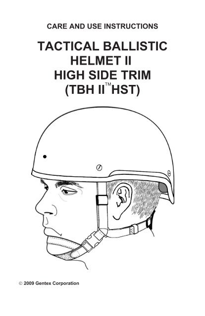
CARE AND USE INSTRUCTIONSTACTICAL BALLISTICHELMET IIHIGH SIDE TRIM(TBH II HST) 2009 <strong>Gentex</strong> <strong>Corporation</strong>
ContentsFEATURES . . . . . . . . . . . . . . . . . . . . . . . . . . . . . . . . . . . 1COMPONENT DESCRIPTION . . . . . . . . . . . . . . . . . . . . . . . . . 2Helmet Shell . . . . . . . . . . . . . . . . . . . . . . . . . . . . . . . . . . . 2Retention Assembly . . . . . . . . . . . . . . . . . . . . . . . . . . . . . . . 3Suspension System . . . . . . . . . . . . . . . . . . . . . . . . . . . . . . . 4HELMET PREPARATION . . . . . . . . . . . . . . . . . . . . . . . . . . . . 5Determining Helmet Size . . . . . . . . . . . . . . . . . . . . . . . . . . . . 5Checking Pad Suspension Fit (Part Number 05D11980-20) . . . . . . . . . 7Checking Pad Suspension Fit(Part Number 05C11950-3 or 05C11950-4) . . . . . . . . . . . . . . . . . . . 9Adjusting Helmet with X-style Retention . . . . . . . . . . . . . . . . . . . 10Adjusting Helmet with H-style Retention . . . . . . . . . . . . . . . . . . . 11Installing Optional NVG Mounting Bracket (One-Hole Helmet Shell). . . . 12Installing Optional Quick-Disconnect NVG Mounting Kit(One-Hole Helmet Shell) . . . . . . . . . . . . . . . . . . . . . . . . . . . . 13Installing Optional NVG Mounting Bracket (Three-Hole Helmet Shell). . . 14DONNING/DOFFING/OPERATION . . . . . . . . . . . . . . . . . . . . . . 15Helmet with X-style Retention . . . . . . . . . . . . . . . . . . . . . . . . . 15Helmet with H-style Retention . . . . . . . . . . . . . . . . . . . . . . . . . 16MAINTENANCE . . . . . . . . . . . . . . . . . . . . . . . . . . . . . . . . 17Preventive Maintenance Checks . . . . . . . . . . . . . . . . . . . . . . . 17Cleaning . . . . . . . . . . . . . . . . . . . . . . . . . . . . . . . . . . . . . 17Troubleshooting . . . . . . . . . . . . . . . . . . . . . . . . . . . . . . . . 18REMOVAL AND REPLACEMENT OF COMPONENTS . . . . . . . . . . . . 19Chin Strap (X-style Retention Only). . . . . . . . . . . . . . . . . . . . . . 19Nape Pad (H-style Retention Only) . . . . . . . . . . . . . . . . . . . . . . 20Retention Straps (H-style Retention Only) . . . . . . . . . . . . . . . . . . 20Pad Suspension Assembly (Part Number 05D11980-20) . . . . . . . . . . 21Pad Suspension Assembly(Part Number 05C11950-3 or 05C11950-4) . . . . . . . . . . . . . . . . . . 22Retention Assembly (X-style and H-style) . . . . . . . . . . . . . . . . . . 23PARTS LIST . . . . . . . . . . . . . . . . . . . . . . . . . . . . . . . . . . 24OPTIONS . . . . . . . . . . . . . . . . . . . . . . . . . . . . . . . . . . . . 26
TACTICAL BALLISTIC HELMET II HIGH SIDE TRIM(TBH IIHST)FEATURES• The <strong>helmet</strong> (Figure 1) is <strong>trim</strong>med <strong>high</strong>er on the <strong>side</strong>s than the standardTBH II or ACH <strong>helmet</strong>s to accommodate various headsets with earcupsthat protrude outward toward the bottom, such as GenCOM III andComtac headsets.• The <strong>helmet</strong> shell provides <strong>ballistic</strong> protection for the covered area inaccordance with MIL-STD-662, 2150 FPS and Level IIIA velocities perPS-0428/A13244.• A reduced profile provides expanded upward and peripheral field of viewfor improved situational awareness.• The <strong>helmet</strong> provides improved interface with protective goggles, NVGcomponents, sighting systems, and other equipment.• A four-point, fully adjustable retention system provides stability andcomfort.• The suspension system includes a pad suspension system for uniformcompression and a snug fit. Some pad suspension systems are designedto accommodate headband-style headsets.• A compatible integrated communication system, a night vision goggle(NVG) mounting bracket, and various <strong>helmet</strong> covers are available.• The <strong>helmet</strong> is available in sizes Medium, Large, and X-Large and withvarious colors and options as described on Pages 24-26.Helmet shellPadsuspensionsystemRetentionsystemTBH IIis a trademark of <strong>Gentex</strong> <strong>Corporation</strong>.Figure 1. TBH II HST Helmet1
COMPONENT DESCRIPTIONHelmet ShellThe <strong>ballistic</strong> composite <strong>helmet</strong> shell (Figure 2) incorporates state-of-the-artmaterials to enhance protection with reduced weight. It is available in three sizes.The <strong>helmet</strong> shell may have one or three pre-drilled holes at the front to permit theattachment of various styles of NVG mounting brackets.Helmet shell,non-NVG(No holes)Helmet shell,one-hole NVGHelmet shell,three-hole NVGHoleHolesFigure 2. Helmet Shell2
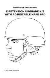
Retention AssemblyThe retention assembly (Figure 3) provides stability and comfort. It is available intwo styles: an X-style retention (in two sizes and several colors), which includesa nape pad, an adjustable chin strap, and straps with slide adjustments; and anH-style retention (universal size, Foliage Green), which includes a chin strap, anape pad, and straps with ladder-lock adjustments.Helmet with X-style retentionSlideadjustmentsNape padChin strap(adjustable)Helmet with H-style retentionLadder locks(two front,two rear)Nape padChin strapFigure 3. Retention Assembly3
Measuring Head Circumference1. Use a tape measure asshown in Figure 7 tomeasure the maximum headcircumference (to the nearest1/16 inch) above the ears.2. Record the measurement.Selecting Helmet SizeReferring to Table 1, selectthe <strong>helmet</strong> size based onhead length, head breadth,and head circumference.TapemeasureFigure 7. Measuring Head CircumferenceTable 1. Sizing ParametersHELMETSIZEHEAD LENGTH(Inches)HEAD BREADTH(Inches)HEAD CIRCUMFERENCE(Inches)Medium < 7-13/16 < 6-1/8 < 22-5/8Large 7-13/16 to 8-1/8 6-1/8 to 6-5/16 22-5/8 to 23-3/8X-Large >8-1/8 >6-5/16 >23-3/8NOTE:• The sizing parameters for the <strong>helmet</strong>s with fitting pads are based on afitting pad compression of approximately 30 percent. This is therecommended compression for optimum <strong>helmet</strong> stability.• The sizing parameters for the <strong>helmet</strong>s are approximate. Dependingupon the wearer’s individual head shape, the next larger or smaller sizemay be needed.• If the <strong>helmet</strong> will be worn with an M-40 respirator or a GenCom III orPeltor headset, and a head measurement is near the maximumparameter for a given size (as specified in Table 1), a larger sizemay be needed.Peltor is a trademark of Aearo Company.6
Checking Pad Suspension Fit(Part Number 05D11980-20)1. Have the wearer don the <strong>helmet</strong>. Allow the <strong>helmet</strong> to settle on the head for afew minutes before checking the fit.2. Ensure that the front pads are just above the eyebrows. If the <strong>helmet</strong> is too<strong>high</strong>, have the wearer remove the <strong>helmet</strong>. Referring to Figure 8, adjust theheight as follows:a. Remove the two crown pads, noting their position in<strong>side</strong> the <strong>helmet</strong>.b. Remove one or both 1/4-inch-thick foam pads from each crown padcover.c. Reinstall both crown pads (with the 1/2-inch-thick foam pad in<strong>side</strong>each one) in the <strong>helmet</strong> in the same positions from which they wereremoved. Ensure that the opening in each crown pad cover faces thetop of the <strong>helmet</strong>. If the wearer uses a headset, space the crown pads toaccommodate the headband of the headset.d. Have the wearer don the <strong>helmet</strong>. Recheck the <strong>helmet</strong> height.(Continued on next page)WARNING• Ensure that all <strong>helmet</strong> adjustment mechanisms are properly adjusted fora snug, secure fit at all times when the <strong>helmet</strong> is worn. Failure to do socan result in an unstable <strong>helmet</strong> that will not protect the wearer.• Each pad contains one 1/2-inch-thick foam pad and two 1/4-inch-thickfoam pads in<strong>side</strong> the cover. For impact protection and <strong>helmet</strong> stability,you must keep all 1/2-inch-thick foam pads in<strong>side</strong> the covers and allpads properly installed in the <strong>helmet</strong> when the <strong>helmet</strong> is worn. Removethe 1/4-inch-thick pads only where necessary to adjust the fit.PADDETAILCrownpads¼-inchthickfoampads½-inchthickfoampadPad coverFigure 8. Crown Pads7
3. Ensure that the <strong>helmet</strong> fit is snug and secure, yet comfortable. If the <strong>helmet</strong>is too tight, have the wearer remove the <strong>helmet</strong>, refer to Figure 9, and adjustthe front and rear pads as follows:a. Remove the front or rear pads from the <strong>helmet</strong> as needed, noting theirposition in<strong>side</strong> the <strong>helmet</strong>.b. Remove one or both 1/4-inch-thick foam pads from front or rear padcover.c. Reinstall both rear pads (with at least the 1/2-inch-thick foam padin<strong>side</strong> each one) in the <strong>helmet</strong> in the same positions from which theywere removed. Ensure that the opening in each crown pad cover facesthe rear of the <strong>helmet</strong>.d. Have the wearer don the <strong>helmet</strong> again. Recheck the fit.4. Proceed to Adjusting Helmet with X-style Retention (Page 10) orAdjusting Helmet with H-style Retention (Page 11).Front padsPADDETAILTwo1/4-inchthickfoam padsOne1/2-inchthickfoam padOpening incloth coverRear padsFigure 9. Adjusting Rear and Front Pads8
Checking Pad Suspension Fit(Part Number 05C11950-3 or 05C11950-4)WARNINGEnsure that all <strong>helmet</strong> adjustment mechanisms are properly adjusted fora snug, secure fit at all times when the <strong>helmet</strong> is worn. Failure to do socan result in an unstable <strong>helmet</strong> that will not protect the wearer.1. Have the wearer don the <strong>helmet</strong>. Allow the <strong>helmet</strong> to settle on the head for afew minutes before checking the fit.• If the 1-inch-thick pads are installed and the <strong>helmet</strong> is too tight, removethe 1-inch-thick pads and install the -inch-thick pads as shown inFigure 10. (Pads must be ordered separately.)• If the -inch-thick pads are installed and the <strong>helmet</strong> is too loose, removethe -inch-thick pads and install the 1-inch-thick pads as shown inFigure 10. (The 1-inch-thick pad set has a -inch thick crown pad.)NOTE: The <strong>helmet</strong> is only provided with one thickness of pads. The usermust order the other thickness if needed.2. Proceed to Adjusting Helmet with X-style Retention (Page 10) orAdjusting Helmet with H-style Retention (Page 11).Rectangular padLateral padLateral padCrown padLateral padLateral padRectangular padFigure 10. Pads Installed9
Adjusting Helmet with X-style Retention1. Referring to Figure 11, do the following:a. Buckle the chinstrap.WARNINGEnsure that all <strong>helmet</strong> adjustment mechanisms are properly adjusted fora snug, secure fit at all times when the <strong>helmet</strong> is worn. Failure to do socan result in an unstable <strong>helmet</strong> that will not protect the wearer.b. Adjust the nape strap for a snug, secure, comfortable fit at the nape.c. Tighten the chin strap by pulling on the ends until the fit is snug, secure,and comfortable. Reattach the ends to the pile fastener when thedesired fit is attained.2. If the retention straps seem too long or too short, refer to Figure 11 andmove the slide adjustments up or down.3. Check the <strong>helmet</strong> stability by attempting to rock the <strong>helmet</strong> back and forth onthe head. If the <strong>helmet</strong> rocks back and forth, it is not stable. Adjust the napestrap further until the <strong>helmet</strong> is stable.4. Repeat Steps 1 through 3 as necessary. Recheck <strong>helmet</strong> stability; no strapsshould be loose.5. Release the buckle to remove the <strong>helmet</strong>.Slide adjustment(both <strong>side</strong>s)Pile fastenerBuckleEnd of chin strap (both <strong>side</strong>s)Nape strapadjustment(both <strong>side</strong>s)Figure 11. X-style Retention Adjustment10
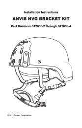
Installing Optional Quick-Disconnect NVG Mounting Kit(One-Hole Helmet Shell)To install the quick-disconnect NVG mounting kit (Figure 14), you must:• Attach the mounting bracket to the <strong>helmet</strong>.• Attach the NVG mounting base to the mounting bracket.• Affix the pile fasteners to the back of the <strong>helmet</strong> (to hold the ANVISbattery pack).• Modify the ANVIS mount (components not included with kit).Refer to TP0279 (included with the kit) for more information.Attaching mounting bracketto <strong>helmet</strong>Attaching NVG mounting baseto mounting bracketMountingbracketMountingbaseAffixing pile fasteners to <strong>helmet</strong>Modifying ANVIS mount (not included)Pile fasteners(back of <strong>helmet</strong>)ANVIS mountFigure 14. Attachment of Quick-Disconnect Mounting Kit (05C12036-2)13
DONNING/DOFFING/OPERATIONWARNINGEnsure that all <strong>helmet</strong> adjustment mechanisms are properly adjusted fora snug, secure fit at all times when the <strong>helmet</strong> is worn. Failure to do socan result in an unstable <strong>helmet</strong> that will reduce protection to the wearer.Helmet with X-style Retention1. Referring to Figure 16, don the <strong>helmet</strong>, ensuring that the <strong>helmet</strong> rests justabove the eyebrows.2. Buckle the chinstrap.3. As needed, adjust the nape strap for a snug, secure fit.4. As needed, adjust the chin strap as follows:a. Detach the ends of the chin strap from the pile fastener.b. Pull on the ends until the chinstrap fits snugly, securely, andcomfortably.c. Reattach the ends of the chinstrap securely to the pile fastener.5. To doff the <strong>helmet</strong>, unbuckle the chinstrap and remove the <strong>helmet</strong> from thehead.Pile fastenerEnd of chin strap(both <strong>side</strong>s)BuckleNape strapadjustment(both <strong>side</strong>s)Figure 16. Helmet with X-style Retention15
Helmet with H-style Retention1. Referring to Figure 17, don the <strong>helmet</strong>, ensuring that the <strong>helmet</strong> rests justabove the eyebrows.2. Buckle the chinstrap.3. As needed, adjust the nape strap for a snug, secure fit.4. As needed, tighten the front and rear straps.5. To doff the <strong>helmet</strong>, unbuckle the chinstrap and remove the <strong>helmet</strong> from thehead.Front strap (two places)NapepadNape strapRear strapBuckleRear of retentionChin strapFigure 17. Helmet with H-style Retention16
MAINTENANCEPreventive Maintenance ChecksTable 2 lists the preventive maintenance tasks for each component and refersyou to the appropriate procedure.Table 2. Preventive Maintenance ChecksCOMPONENT EXAMINE FOR: HELMET IS NOT READY IF:ChinstrapPadsRetentionAssemblyHelmet ShellBroken buckles; torn orfrayed webbing, wornhook/pile fastenersWorn hook/pilefasteners or foam; tornfabric or seamsTorn/frayed webbing;broken nape strapbuckles; worn nape pad;worn buckle padHoles, cracks, ordelaminations greaterthan 2 inchesBuckles are broken; webbing istorn or frayed; hook/pilefasteners do not secureHook/pile fasteners or foam areworn, fabric or seams are tornWebbing is torn or frayed; napestrap buckles are broken; napepad is worn; buckle pad is wornHelmet shell has holes, cracks,or delaminations greater than 2inchesCleaningTable 3 lists the cleaning procedure for each of the <strong>helmet</strong> components.Table 3. CleaningCOMPONENTHelmet ShellLeather ComponentsRetention AssemblyPadsPROCEDUREWipe clean with damp cloth.Clean with soap, rinse thoroughly, wipe dry withclean cloth.Wipe clean with damp cloth.Machine wash with mild detergent in cold water.17
TroubleshootingListed below are the troubleshooting tasks for each component, along with theappropriate repair procedure.1. Malfunction: Unable to fasten or adjust chin strapTest/Inspection: Inspect chin strap for defective webbing, buckles, orhook/pile fasteners.Corrective Action: Replace chin strap as on Page 19 (for X-styleretention) or replace retention straps as on Page 20.2. Malfunction: Unable to attain/maintain <strong>helmet</strong> stabilityTest/Inspection: Inspect retention assembly for defective buckles,worn buckle pads, torn/frayed webbing, or worn napepad.Corrective Action: Replace retention assembly as on Page 23.3. Malfunction: Helmet shell appears damaged.Test/Inspection: Inspect <strong>helmet</strong> shell for holes or cracks.Corrective Action: Obtain new <strong>helmet</strong>.18
REMOVAL AND REPLACEMENT OF COMPONENTSChin Strap (X-style Retention Only)Removal1. Referring to Figure 18, unfasten the chin strap buckle on the left <strong>side</strong>(as worn) of the retention assembly.2. Unlace the chin strap from the right <strong>side</strong> (as worn) of the retention assembly.Installation1. Lace the chin strap through the buckle on the right <strong>side</strong> (as worn) of theretention assembly.2. Don the <strong>helmet</strong>. Fasten the chin strap to the buckle on the left <strong>side</strong>(as worn) of the retention assembly.3. Check the fit in accordance with Page 10. Make any necessary adjustments.RIGHT SIDE(AS WORN)Lace/unlaceFigure 18. Chin StrapFasten/unfasten19
Nape Pad (H-styleRetention Only)Removal1. Referring to Figure 19,withdraw the nape strapfrom the webbing loops ofthe back of the nape pad.2. Remove the nape pad.Installation1. Position the nape pad at therear of the <strong>helmet</strong>.2. Insert the nape strapthrough the webbing loopson the back of the nape pad.3. Check the fit in accordancewith Page 11, and adjust thenape pad for a snug fit.Rear view ofnape padNape strapWebbing loopsFigure 19. Nape Pad and StrapRetention Straps (H-styleRetention Only)Removal1. Referring to Figure 20, slidethe four elastic webbingloops down to free the endsof the retention straps.2. Unlace the ends of theretention straps from thefour ladder locks.Installation1. Lace the ends of the strapsthrough the four ladderlocks.2. Slide the four elasticwebbing loops over theends of the straps.3. Check the fit in accordancewith Page 11, and adjust thestraps for a snug fit.Strap attachmentpoint (four places)LadderlockElasticwebbingloopEnd ofstrapFigure 20. Retention Straps20
Pad Suspension Assembly (Part Number 05D11980-20)Removal1. Referring to Figure 21, remove the pads from the <strong>helmet</strong>, noting theirposition and orientation in the <strong>helmet</strong>.2. Look in<strong>side</strong> each of the removed pads, noting which foam pads are installedin<strong>side</strong> the cover.InstallationWARNINGEach fitting pad contains one 1/2-inch-thick foam pad and two 1/4-inch-thickfoam pads in<strong>side</strong> the cover. For impact protection and <strong>helmet</strong> stability, youmust keep all 1/2-inch-thick foam pads in<strong>side</strong> the fitting pads and all fittingpads properly installed in the <strong>helmet</strong> when the <strong>helmet</strong> is worn. Remove the1/4-inch-thick pads only where necessary to adjust the fit.1. Obtain the replacement pads. If only the 1/2-inch-thick foam pads were usedin the previous pads, remove the 1/4-inch-thick foam pads from thereplacement pads in the same manner. Otherwise, leave the 1/4-inch-thickfoam pads in<strong>side</strong>.2. Install the replacement pads in the <strong>helmet</strong> in the same manner in which theprevious pads were installed. If the wearer uses a headset, space the crownpads to accommodate the headband of the headset.3. Don the <strong>helmet</strong>, and check the fit in accordance with Page 10 (for X-styleretention) or Page 11 (for H-style retention). Make any necessaryadjustments.Front padsPAD DETAILCrownpads1/4-inchthickfoampads1/2-inchthickfoampadCoverRear padsFigure 21. Pad Suspension Assembly21
Pad Suspension Assembly(Part Number 05C11950-3 or 05C11950-4)RemovalReferring to Figure 22, remove the pads from the <strong>helmet</strong>, noting theirposition and orientation in the <strong>helmet</strong>. Also note the pad thickness(05C11950-3 is 3/4 inch thick; 05C11950-4 is 1 inch thick).Installation1. Install the replacement pads (of the same thickness) in the <strong>helmet</strong> in thesame manner in which the previous pads were installed.2. Don the <strong>helmet</strong>, and check the fit in accordance with with Page 10 (forX-style retention) or Page 11 (for H-style retention). Make any necessaryadjustments.Rectangular padLateral padLateral padCrown padLateral padLateral padRectangular padFigure 22. Pads Installed22
Retention Assembly (X-style and H-style)Removal1. Referring to Figure23, remove the frontand rear pads asnecessary to reachthe attachinghardware of theretention assemblyon the in<strong>side</strong> of the<strong>helmet</strong>, noting theposition of the pads.NOTE: Figure 24shows the X-styleretention assembly.The same procedureapplies to the H-styleretention assembly2. Referring to Figure24, remove the fourscrews and nutsattaching theretention assemblyto the <strong>helmet</strong>.Installation1. Install thereplacementretention assemblywith the screws andnuts.2. Reinstall the frontand rear pads in thepositions from whichthey were removed.3. Don the <strong>helmet</strong>,check the fit inaccordance with withPage 10 (for X-styleretention) or Page 11(for H-styleretention). Make anynecessaryadjustments.Front padRear padFigure 23. Pads to Be RemovedRetention strapScrewScrewsFront padNutRear padINSIDEVIEW OFHELMETFigure 24. Retention Assembly Hardware23
PARTS LISTOn the next page is a parts list for the TBH II HST <strong>helmet</strong>. The parts listcorresponds to the components shown in Figure 25.For more information, contact <strong>Gentex</strong> <strong>Corporation</strong>, P.O. Box 315, Carbondale,PA 18407, phone (570)282-3550, fax (570)282-8555, www.gentexcorp.com.Helmet shell,no NVG holesHelmet shell,one NVG holeHelmet shell,three NVG holesRetention assembly, X-style,part number 04D11896-1through 04D11896-6Retention assembly, H-style,part number 05D11948-1ScrewNutPads,part number 05C11950-3 (¾ inch thick)or 05C11950-4 (1 inch thick)Adjustable pads,part number 05D11980-20Figure 25. TBH II HST Helmet Assembly24
HelmetSizeTBH II HST Helmet,No NVG HolesTBH II HST Helmet,One NVG HoleTBH II HST Helmet,Three NVG HolesMedium A13244-2* A13244-6* A13244-10*Large A13244-3* A13244-7* A13244-11*X-Large A13244-4* A13244-8* A13244-12*All <strong>helmet</strong>s include:• Screw, shoulder (4 ea.): B12190-1• Nut, conic (4 ea.): 04B11815-1• Instruction Booklet: TP0348* Each <strong>helmet</strong> part number is followed by three suffixes. The first suffix (A through J)denotes <strong>helmet</strong> shell color. The second suffix (01 through 07) denotes retentionassembly size and color. The third suffix (A through C) denotes the pad style.Helmet shell color suffixes:A (Black)B (Green)C (Olive Drab)D (CHP Blue)E (UN Blue)F (Desert Tan)G (Foliage Green)H (Coyote Brown)J (Met Blue)Example:A13244-2A05AA13244-2 . . . . TBH II HST Helmet,Medium, No NVG HolesA . . . . . . . .Black <strong>helmet</strong> shell05 . . . . . . . . Small/Medium Blackretention assemblyA . . . . . . . .3/4-inch thick pad setpart number 05C11950-3Retention assembly suffixes:NOTE: Ensure that the retention assembly size matches the <strong>helmet</strong> size.01 (Small/Medium, Green, part number 04D11896-1)02 (Large/X-Large, Green, part number 04D11896-2)03 (Small/Medium, Foliage Green, part number 04D11896-3)04 (Large/X-Large, Foliage Green, part number 04D11896-4)05 (Small/Medium, Black, part number 04D11896-5)06 (Large/X-Large, Black, part number 04D11896-6)07 (H-style, Universal size, Foliage Green, part number 05D11948-1)Pad suffixes:A (3/4-inch thick pad set, part number 05C11950-3)B (1-inch thick pad set, part number 05C11950-4)C (Adjustable pad suspension, part number 05D11980-20)25
OPTIONSThe following options are available for use with the TBH II HST Helmet. Contact<strong>Gentex</strong> <strong>Corporation</strong> at (570) 282-3550 for more information. Visit our web site atwww.gentexcorp.com and click on "Force Protection" for <strong>ballistic</strong>-protectiveproducts.• Various headsets, including an GDH headset for maximum situationalawareness and a modified GenCOM III headset for <strong>high</strong>-noiseenvironments• NVG Mounting Bracket, Lever (NVG Front Bracket Assembly),<strong>Gentex</strong> part number 03B11760-1; NSN 5430-01-509-1467• Ballistic Optical Armor (BOA) Goggles• Eye Protective System-21 (EPS-21) Goggles• Ballistic Neck Protectors26
TP0348 NOVEMBER 2009