EDKII_UserManual_0_7.pdf - FTP
EDKII_UserManual_0_7.pdf - FTP
EDKII_UserManual_0_7.pdf - FTP
- No tags were found...

Create successful ePaper yourself
Turn your PDF publications into a flip-book with our unique Google optimized e-Paper software.
FIGURESFigure 1 Packages Dependency .........................................................................12Figure 2 Startup flow for Duet environment ........................................................42Figure 3 Select "Boot Manager" Menu ................................................................45Figure 4 Select "EFI Internal Shell" from "Boot Manager" ......................................45Figure 5 Select "Boot Maintenance Manager" from Front Page ..............................46Figure 6 Select "Boot From File" menu ..............................................................47Figure 7 Select disk contains "EFI Shell" binary image ..........................................47Figure 8 Select Shell.efi binary image ................................................................48Figure 9 EFI network driver layout.....................................................................50Figure 10 Debug/Info message output ...............................................................52Figure 11 INT 3 is triggered..............................................................................53Figure 12 Select System Debugger ....................................................................53Figure 13 Debugger is launched at first break point..............................................54v March, 2010
TABLESTable 1 Microsoft Visual Studio .........................................................................13Table 2 Intel C++ Compiler ..............................................................................13Table 3 Microsoft Window Driver Development Kit (DDK) ......................................14Table 4 Software Needed by GCC Tool Chain.......................................................14Table 5 ACPI Compiler .....................................................................................15Table 6 Microsoft Visual Studio.........................................................................15Table 7 Intel C++ Compiler for EFI Byte Code Compiler........................................16Table 8 The list of supported tool chain tags .......................................................21Table 9 Internal shell commands.......................................................................48vi March, 2010
viii March, 2010
1<strong>EDKII</strong> IntroductionThis document provides detailed instructions for downloading, configuring and buildingan <strong>EDKII</strong> project as well as running <strong>EDKII</strong> Emulation Environments.1.1 OverviewThis chapter describes the features introduced by <strong>EDKII</strong> project and elaborates therole played by several key features. This chapter provides readers with a basicunderstanding on <strong>EDKII</strong> after reading.The features introduced by <strong>EDKII</strong> include:Minimal unit of distribution.<strong>EDKII</strong> introduces the concept of Packages. It is the basic unit of coderelease. Compared to EDK, EDK II users can release and work with"Packages", as opposed to the “Whole Source Tree”.Different implementations for the same functionality.<strong>EDKII</strong> introduces the concept of Library Class/Library Instance. Libraryclass is a set of standard interfaces for common support routines, andlibrary instance supplies the implementation of these interfaces. Platformintegrator can select different implementations upon various applicationscenarios.Uniform configuration interface for module writers.Platform Configuration Database (PCD) is a mechanism that providesmodule writers a uniform interface to extract external input informationdetermined in build time or run time of firmware. This mechanismstandardizes the exposure of platform and module settings that can inturnfacilitate platform porting.Cross-architecture and Cross-compiler ability.<strong>EDKII</strong> source supports various architectures, such as IA32, X64, IA64, andvarious tool-chains, such as Microsoft VC, GNU GCC and Intel ICC. Tosupport this capability, <strong>EDKII</strong> offers specific implementations forarchitecture-related or compiler-related functions in libraries.Binary compatibility for pre-PI modules.The <strong>EDKII</strong> provides thunk drivers to address the binary compatibilityissues with using existing pre-PI EDK modules in a platform comprised ofmostly EDK II modules.1
Refined basic APIs (known as Module Development Environment Library).In <strong>EDKII</strong> there are many APIs that are refined and appended for moduledevelopers, such as the PCI library, I/O library and Print library, etc.Enhanced build system.Its infrastructure is based on Python that is independent of the operatingsystem. It exposes several configuration files that a user can utilize tochoose the various tool-chains, even the build rule or generated target.<strong>EDKII</strong> provides definitions and the library interface required by EDK modules, so itmakes EDK modules that can be integrated into the <strong>EDKII</strong>.1.1.1 UEFI and PIThe Unified Extensible Firmware Interface (UEFI) Specification defines a group ofstandard interfaces between the operating system (OS) and the platform firmware.UEFI's predecessor was the Extensible Firmware Interface (EFI), originally developedby Intel. Intel later contributed ownership of the EFI specification to a non-profit,industry trade organization The Unified EFI Forum, who is now responsible for itsdevelopment and promotion.The UEFI Platform Initialization Specification (also known as the “PI”) is a set ofspecifications developed, in conjunction with UEFI, by The Unified EFI Forum. The PISpecification was preceded by Intel Platform Innovation Framework for EFI (alsoknown as “the Framework”). While UEFI/EFI specifies the OS-to-firmware interface,the PI/Framework specification specifies the structure used to build the firmwarebeneath the OS-to-firmware interface.1.1.2 EDK & <strong>EDKII</strong>1.1.2.1 PackageThe EFI Developer Kit (EDK) is an Open Source release of the FrameworkFoundations, defined in the Framework Core Interface Specifications (CIS), plus a setof sample drivers and three sample targets implemented for the Nt32, Unix, and DUETplatforms. In addition to Open Sourcing the Framework Foundation code, the EDKallows for the development, debugging, and testing of EFI and DXE drivers, OptionROMs, and pre-Boot applications.To solve customer feedback exposed by using EDK, Intel started a remodeling plannow known as <strong>EDKII</strong>. It focuses on how to make it easy for customers to write aspecific kind of module, to port and to customize modules to a platform. The followingsections elaborate on several key concepts introduced by <strong>EDKII</strong>, such as Package,Library Class/Library Instance and PCD, etc.The EDK could not be compiled without the entire source tree. Furthermore, the unitof distribution required the EDK as the whole tree. To solve this issue, <strong>EDKII</strong>introduced the new concept, the "Package". Using this, a release and its work can bemade with "Packages" as opposed to requiring the “Whole Source Tree”.2 March, 2010
A package is the minimal unit of distribution—as well as providing a natural split in abig project—which serves various purposes. For example, from the viewpoint ofhardware a developer may divide CPU/chipset/platform related definitions and driversinto three individual packages that facilitate a user's distribution and reuse.Developers also can put all modules that are independent of various platforms into asingle package. Therefore, developers only need focus on platform-specific code whenporting to a new platform.The <strong>EDKII</strong> provides a set of packages, which are introduced in next chapter. As someof the packages are not necessary for building a given module or firmware, Firmwaredevelopers can only choose relevant packages to finish building or releasing.Additionally, a developer can also create and distribute his or her own package basedon the <strong>EDKII</strong> code base. For further information, please refer to the <strong>EDKII</strong> PackageSpecification.1.1.2.2 Library class/Library InstanceBecause demand exists for the same functionality in the development of firmware, butdifferent implementations may be needed, such as:using C code to provide cross-architecture ability rather than using assemblyto provide better performance,using I/O port to perform PCI configuration cycles but not using memory I/Oinstructions.The Library Class is a set of standard API definitions that are used to provide certainfunctionality. A module writer can directly use them to program. A library instancesupplies the implementation of these APIs. The relationship between library class andlibrary instance is one-to-many. A library class may have multiple implementations,that is, multiple library instances.A module only depends on a library class and not concrete implementations, so thesame module source code can be easily configured to link with different libraryinstances for various requirements.The <strong>EDKII</strong> provides many library classes/library instances to facilitate userdevelopment in the MdePkg.For example, MdePkg provides a library class named BaseMemoryLib, in which thereare many APIs related to memory operation. For this library class there are multiplelibrary instances, such as the following:one implemented in C to cross platform,one implemented in ASM to improve the efficiency of memory operation..The platform integrator can selectively choose various library instances.1.1.2.3 Platform Configuration DatabasePCD is a unified mechanism used by a module to extract information from externalsources and control procedure behavior. The information can come from manydifferent places. Information could be knownat compile time,3 March, 2010
at flash image generation time,on the fly (when firmware code is being executed).The module writer does not need to know where the information has come frombecause the platform developer can make the selection. The module's source code canremain unchanged to support multiple platforms, as all the external input informationis extracted by unified PCD interfaces.For example, a PCD, "PcdDebugPrintErrorLevel", is used to control the debug printlevel. Thus, a module developer only needs to call the PCD interface PcdGet32(PcdDebugPrintErrorLevel) to extract its value. The value of the PCD is determined bya platform configuration in the module build. Various values may cause differentbehavior, such as enabling or disabling the display of particular debug printstatements.1.2 Related Information1.2.1 Useful publications and sources of informationUnified Extensible Firmware Interface Specification Version 2.1, The Unified EFIForum, Inc, 2007, http://www.uefi.org.Extensible Firmware Interface Specification Version 1.10, Intel, 2001,http://developer.intel.com/technology/efi.Intel® Platform Innovation Framework for EFI Specifications, Intel, 2006,http://www.intel.com/technology/framework/.1.2.1.1 TianoCore.org site documentationhttp://sourceforge.net/projects/edk2/files/EDK II INF File Specification, Version 1.2, Intel, 2009.EDK II DSC File Specification, Version 1.2, Intel, 2009.EDK II DEC File Specification, Version 1.2, Intel, 2009.EDK II FDF (Flash Description File) File Specification, Version 1,2, Intel, 2009.EDK II Build Specification, Version 1.2, Intel, 2009.1.3 TermsThe following terms are used throughout this document to describe varying aspects ofinput localization:4 March, 2010
EDKEDK IIEFI Developer’s kit, the open source project of the Intel PlatformInnovation Framework for EFI that can be found athttp://sourceforge.net/apps/mediawiki/tianocore/index.php?title=EDK .A generic term to describe the open source project found athttp://sourceforge.net/apps/mediawiki/tianocore/index.php?title=EDK2 .In this document, it refer to the new release of EDK II which support buildinfrastructure that makes use of the Extended INF, DEC and ExtendedDSC.EDK II ModuleA generic term to describe a module that is developed using the newrelease of EDK II project that supports the library class, library instances,packaging concept and Extended INF, DEC and Extended DSC files.EFIGeneric term that refers to one of the versions of the EFI specification: EFI1.02, EFI 1.10, UEFI 2.1, UEFI 2.2 or UEFI 2.3.FrameworkIntel® Platform Innovation Framework for EFI consists of the Foundation,and other modular components that characterize the portability surface formodular components designed to work on any implementation of theTiano architecture.Library ClassA library class defines the API or interface set for a library. The consumerof the library is coded to the library class definition. Library classes aredefined via a library class .h file that is published by a package. See theEDK 2.0 Module Development Environment Library Specification for a listof libraries defined in this package.Library InstanceAn implementation of one or more library classes. See the EDK 2.0 ModuleDevelopment Environment Package Document athttp://sourceforge.net/projects/edk2/files/ for a list of library defined inthis package.ModuleA module is either an executable image or a library instance. For a list ofmodule types supported by this package, see module type.5 March, 2010
Module TypeAll libraries and components belong to one of the following module types:BASE, SEC, PEI_CORE, PEIM, DXE_CORE, DXE_DRIVER,DXE_RUNTIME_DRIVER, SMM_CORE, DXE_SMM_DRIVER,DXE_SAL_DRIVER, UEFI_DRIVER, or UEFI_APPLICATION. Thesedefinitions provide a framework that is consistent with a similar set ofrequirements. A module that is of module type BASE, depends only onheaders and libraries provided in the MDE, while a module that is ofmodule type DXE_DRIVER depends on common DXE components.PackagePCDPIA package is a container in which a set of modules are organized togetherin accordance with certain purpose or rule.Platform Configuration Database.Platform Initialization Specification.UEFI ApplicationAn application that follows the UEFI specification. The only differencebetween a UEFI application and a UEFI driver is that an application isunloaded from memory when it exits regardless of return status, while adriver that returns a successful return status is not unloaded when itsentry point exits.UEFI DriverA driver that follows the UEFI specification.UEFI Specification Version 2.1, 2.2 and 2.3A series of the UEFI specifications released by the Unified EFI Forum.These specifications build on the EFI 1.10 specification and transfersownership of the EFI specification from Intel to a non-profit, industry tradeorganization.Unified EFI ForumA non-profit collaborative trade organization formed to promote andmanage the UEFI standard. For more information, see www.uefi.org.1.4 Target AudienceThis document is intended to be a reference for those who are just starting <strong>EDKII</strong>development, for the following:• IBVs and OEMs who will implement UEFI/PI drivers or other firmware productsbased on <strong>EDKII</strong>.6 March, 2010
• IHVs who will be create supported firmware drivers for hardware device, as well asplatform integrators using <strong>EDKII</strong> components and modules.7 March, 2010
8 March, 2010
2Setting Up <strong>EDKII</strong> DevelopmentEnvironmentThis chapter explains how to download the <strong>EDKII</strong> source code, and introduces thethird-party software needed by the <strong>EDKII</strong> build process. This chapter also introducesthe basic structure of the <strong>EDKII</strong> source code and provides a quick start to build andlaunch an NT32 emulation platform.2.1 How to Get the <strong>EDKII</strong> SourceTianoCore.org(http://sourceforge.net/apps/mediawiki/tianocore/index.php?title=Welcome_to_TianoCore ) is the website of the EFI and Framework Open Source Community, wherethere are the documentation, source and binaries available. Users may also access theForums, Issue Tracking, Mailing Lists, RSS Feeds and Source Control on this website.The Source Control is Subversion for all projects on this website, including <strong>EDKII</strong>project.There are systematic instructions at(http://sourceforge.net/apps/mediawiki/tianocore/index.php?title=Step-bystep_instructions), which help new developers set up their build environment andbuild their first EDK II package. The instructions also cover setting up builds for Unixlikeplatforms, including building a GCC UEFI cross compiler for EDK II development.The <strong>EDKII</strong> source repository ishttps://edk2.svn.sourceforge.net/svnroot/edk2/trunk/edk2/.Before downloading <strong>EDKII</strong> source, obtain an account on http://www.sourceforge.net.Please register it at https://sourceforge.net/account/registration/.2.2 <strong>EDKII</strong> Packages<strong>EDKII</strong> source consists of several packages, shown in the following directories of thedownload directory.BaseToolsProvides the binary build tools and the templates of configuration files forbuilding. Build tools belong to another project, please visithttp://sourceforge.net/apps/mediawiki/tianocore/index.php?title=Edk2-buildtools to get the source codes of build tools.9
ConfMdePkgOnly has one readme.txt file. This directory will be used to contain theconfiguration files of building target and compiler parameters used forbuilding.Declares PROTOCOLs, PPIs, GUIDs and related data structures defined inUEFI, EFI, and PI Specifications (http://www.uefi.org) and industrystandards. In addition, this package encompasses library instancesdefined in Module Development Environment, which provides services forall the execution phases in the Intel Platform Innovation Framework forEFI.MdeModulePkgProvides a group of modules crossing platforms, based on UEFI, EFI, andPI Specifications. It also includes the libraries instances serviced for thesemodules.IntelFrameworkPkgDeclares PROTOCOLs, PPIs, GUIDs and related data structures are definedin Intel Platform Innovation Framework Specification for EFI(http://developer.intel.com/technology/framework/spec.htm). In addition,this package encompasses library instances based on Intel PlatformInnovation Framework Specification.IntelFrameworkModulePkgProvides a group of libraries instances and modules crossing platforms,based on Intel Platform Innovation Framework Specification. It alsoincludes the libraries instances serviced for these modules.EdkShellPkgProvides the build instructions of Shell project. EFI Shell belongs toanother project, please visithttp://sourceforge.net/apps/mediawiki/tianocore/index.php?title=Efi-shellfor more details.EdkShellBinPkgProvides the binary Shell files and the binary shell applications fordifferent CPUs architectures.EdkFatBinPkgProvides the binary FAT drivers for different CPUs architectures. FAT driverbelongs to another project, please visithttp://sourceforge.net/apps/mediawiki/tianocore/index.php?title=Edk2-fatdriver2 to get the source code of FAT driver.10 March, 2010
Nt32PkgUnixPkgDuetPkgLaunched at 32-bit Microsoft Window operating system and provides aUEFI runtime environment.Launched in general 32-bit Unix-like operating system, such as a UNIX orLinux distributions.Provides UEFI runtime environment based on legacy BIOS on the realmachine.OptionRomPkgShows the sample drivers to build PCI compliant Option ROMimage fordifferent CPUs architectures.EdkCompatibilityPkg(ECP)Includes EDK style definitions of EFI1.10, EFI2.0 and all definitions of IntelFramework Specification and the EDK libraries instances to allow EDK stylemodules to be used in <strong>EDKII</strong> context. It also has some thunk drivers thatprovide transition between the different protocols defined in UEFI2.1/PI1.0specifications and the Intel Platform Innovation Framework Specification.The primary goal of the ECP is to enable build compatibility of EDKmodules in the <strong>EDKII</strong> and to address the binary compatibility issues withusing existing pre-PI EDK modules in a platform comprised of mostly<strong>EDKII</strong> modules.PcAtChipsetPkgUefiCpuPkgOvmfPkgDesigned to public interfaces and implementation that follows PcAt defacto standard.Provides UEFI compatible CPU modules and libraries.Aims to support firmware for Virtual Machines using the edk2 code base.More information can be found at:http://sourceforge.net/apps/mediawiki/tianocore/index.php?title=OVMF .Each package has the similar structure of directories. For example, MdePkg has thefollowing directories and sub-directories:Include\-- public header files of MDE PackageIa32\-- internal header files specified to IA-32 architectureX64\ -- internal header files specified to x64 architectureIpf\-- internal header files specified to IPF architecture11 March, 2010
Ebc\Uefi\Pi\Protocol\Ppi\Guid\-- internal header files specified to EBC architecture-- public header files containing UEFI2.1 definitions-- public header files containing PI1.0 definitions-- public header files containing PROTOCOLs definitions-- public header files containing PPIs definitions-- public header files containing GUIDs definitionsIndustryStandard\-- public header files containing Industry StandardLibrary\-- public header files containing MDE Libraries classesLibrary\-- MDE libraries instancesThe internal header files only could be referred by those public header files.A dependency relationship exists among <strong>EDKII</strong> packages. For example, the module inMdeModulePkg uses the protocols defined in MdePkg, so MdeModulePkg will depend onMdePkg. The following chart illustrates the dependencies among the packages in<strong>EDKII</strong>.Figure 1 Packages DependencyFrom this chart, the following basic dependencies can be discovered, for example:12 March, 2010
1. To build OptionRomPkg, only MdePkg and BaseTools are required.2. To build EdkCompatibilityPkg, only MdePkg, IntelFrameworkPkg and BaseToolsare required.3. To build EdkShellPkg, only EdkCompatibilityPkg and BaseTools are required.4. To build the NT32/Unix/Duet emulation platforms, MdePkg, MdeModulePkg,IntelFrameworkPkg, IntelFrameworkModulePkg, EdkFatBinPkg,EdkShellBinPkg and BaseTools are required.2.3 Third-Party ToolsBesides downloading <strong>EDKII</strong> source, some third-party tools are still needed to build<strong>EDKII</strong>. The third-party tools include a C compiler and an assembler. An ACPI compileris required to build ACPI table.2.3.1 Target for IA-32 and Intel64 ProcessorsTo build <strong>EDKII</strong> for the platforms based on IA-32 or Intel64 processors, the followingcompiler tool chains may be selected.1. Microsoft Visual StudioOne version of Microsoft Visual Studio from Table 1 may be installed to build<strong>EDKII</strong>.Table 1 Microsoft Visual StudioName Version URLMicrosoft VisualStudio2005Professionalhttp://msdn2.microsoft.com/en-us/vstudioMicrosoft VisualStudio2003 .NET http://msdn2.microsoft.com/en-us/vstudioBy default, the <strong>EDKII</strong> source onhttp://sourceforge.net/apps/mediawiki/tianocore/index.php?title=Edk2is set to use Microsoft Visual Studio 2005 Professional to build the IA-32 andIntel64 processors-based platforms.2. Intel C++ Compiler (ICC)Table 2 Intel C++ CompilerName Version URLIntel C++ Compiler forWindows9.1 http://www.intel.com/support/performancetools/c/windows/index.htmAfter the downloading web page, select the correct version number todownload.13 March, 2010
Build <strong>EDKII</strong> using an Intel C++ Complier requires a Microsoft Visual Studioinstallation. Please refer to Table 1 to install one version of Microsoft VisualStudio.3. Microsoft Windows Driver Development Kit (DDK)To build a physical platform (because it has 16-bit assembly codes) theMicrosoft Windows Driver Development Kit must be installed. Please refer toTable 3 to install it.Table 3 Microsoft Window Driver Development Kit (DDK)Name Version URLMicrosoft WindowsDriver DevelopmentKit (DDK)2790.1830 http://download.microsoft.com/download/9/0/f/90f019ac-8243-48d3-91cf-81fc4093ecfd/1830_usa_ddk.iso4. GCC Tool ChainThere are two GCC tool chains. One is used to build and launch UnixEmulation Platform on platforms based on the IA-32 processor. Another isused to build UEFI images running on the actual platforms.To build and launch Unix Emulation Platform target, requirements include the32-bit Unix-like operating system environments and a group of software thatincludes GNU C Compiler, GNU Binutils, GNU Glib C, X11, SQlite and Python.The software provided by a Unix-like operating system can be used directly, ordownloaded and built as listed in Table 4.Table 4 Software Needed by GCC Tool ChainName Version URLGNU C Compiler (GCC) 4.2.1 http://gcc.gnu.org/gcc-4.2/GNU Binutils 2.17.50 http://ftp.gnu.org/gnu/binutils/GNU Glib C 2.3.6 http://ftp.gnu.org/gnu/glibc/X11 7.2 http://ftp.x.org/pub/X11R7.2/SQLite 3.0 or later http://www.sqlite.orgPython 2.5.2 or later http://www.python.org/To build <strong>EDKII</strong> as a target for IA32 and Intel64 architectures, the updatedsoftware to generate the UEFI images capable of running on actual platformswill be needed. First, the SQLite and Python version listed in the upper tablewill need to be downloaded and installed. Then use the scripthttp://edk2.svn.sourceforge.net/svnroot/edk2/trunk/edk2/BaseTools/gcc/mingw-gcc-build.py to download all needed software and to build automatically.This script belongs to BaseTools project. Use your account onhttp://sourceforge.net/apps/mediawiki/tianocore/index.php?title=Welcome_to_TianoCore to download it.14 March, 2010
5. ACPI CompilerTo build ACPI tables, one of ACPI compilers listed below needs to be installed.Table 5 ACPI CompilerName Version URLACPI ComponentArchitectureMicrosoft ACPISource Language(ASL) Assembler20061109or later3.0.0NT orlaterhttp://acpica.org/downloads/http://www.microsoft.com/whdc/system/pnppwr/powermgmt/default.mspx2.3.2 Target for Intel Itanium Family Processors (IPF)To build <strong>EDKII</strong> for the platforms based on Itanium Processor Family (IPF) processors,the following compiler tool chains may be selected.1. Microsoft Visual StudioTable 6 Microsoft Visual StudioName Version URLMicrosoft VisualStudio2005 Team Suite http://msdn2.microsoft.com/en-us/vstudioWhen installing Microsoft Visual Studio 2005 Team Suite, IA64 support mustbe selected.2. Intel C++ Compiler (ICC)Please refer to Table 2 to install the Intel C++ Compiler. To build <strong>EDKII</strong> withIntel C++ Complier, a Microsoft Visual Studio installation is also required.Please refer to Table 1 to install one version of Microsoft Visual Studio.3. Microsoft Windows Driver Development Kit (DDK)By default, the <strong>EDKII</strong> source onhttp://sourceforge.net/apps/mediawiki/tianocore/index.php?title=Welcome_to_TianoCore is set to use Microsoft Windows Driver Development Kit (DDK) tobuild the Intel Itanium Processor Family processors-based platforms. Pleaserefer to Table 3 to install Microsoft Windows Driver Development Kit (DDK).4. ACPI CompilerTo build ACPI tables, one of ACPI compilers listed in Table 5 must be installed.2.3.3 Target for EFI Byte Code (EBC) ImageThe Intel C Compiler for EFI Byte Code creates EFI Byte Code (EBC) images that canbe executed by systems implementing the EFI 1.10, UEFI 2.0, or later specifications.15 March, 2010
These systems include an EBC interpreter that loads and interprets the EBC image,allowing the image to be executed on multiple platforms and architectures, includingthose based on Intel Itanium processors, IA-32 architecture-based processors, orIntel64 architecture-based processors.Table 7 Intel C++ Compiler for EFI Byte Code CompilerName Version URLIntel C++Compiler for EFIByte Code1.2 http://www3.intel.com/cd/software/products/asmona/eng/compilers/efibc/index.htmTo build EBC image, the Intel C Compiler for EFI Byte Code and Microsoft VisualStudio must be installed. Refer to Table 1 for installation of Microsoft Visual Studio.2.4 A Quick BuildThe following instructions will build and launch an NT32 emulation platformsystematically.1. Enter <strong>EDKII</strong> root directoryRun edksetup.bat --nt322. Run build3. Execute build run16 March, 2010
3<strong>EDKII</strong> Build Process3.1 Basic build steps introductionChapter 2 explained how to build an NT32 platform. In this chapter, the basic buildsteps are introduced in detail.Step 1:Download <strong>EDKII</strong> project as the basic workspace, and install the required tool chain. Ifnecessary, other modules and packages can also be added into this workspace. Thisstep is shown in Chapter 2.Step 2:In the workspace (<strong>EDKII</strong> root directory), run edksetup script to set up the buildenvironment. For an Nt32 platform, the --nt32 option is required to setup the“standard” places for include (.h) and dll files required by the Nt32 platform.Step 3:Configure the active platform, such as build options, target, build tool chain and buildrules. The build configuration is introduced in section 3.2.Step 4:Call build command to build the platform, module or target configured in step 3. Seesection 3.2.2 regarding the build command option. See section 3.5 regarding theplatform build and customization. The module build is introduced in section 3.4. Thebuild targets are listed in the end of this section.Step 5:Post build steps can be done according to custom requirements. For an NT32platform, execute the build run command to run NT32 emulation. For the optionROM image, create the option ROM.The above run is a build target for build command to start NT32 emulation. Besides,there are other useful build targets. They are: build build allBuild all libraries, component PE/COFF images and FV/FD images. build clean17 March, 2010
Clean the intermediate output files (such as the compiled obj files) except thegenerated Makefile files (top level and module makefiles) and AutoGen files.build cleanallClean all generated files and directories during build. build fdsOnly generate FV and FD image.3.2 Build ConfigurationBuild configuration includes three aspects. They are separate for the active platform,the tool chain and build rule. The build configuration information is stored in three txtfiles: target.txt, tools_def.txt and build_rule.txt. Their template that contains thedefault setting provided by <strong>EDKII</strong> is created in the $(WORKSPACE)/Conf directory afterbuild Step 2. The following sections introduce each txt file.3.2.1 Configure the active platformThe active platform is the built target. It can be set in the target.txt file or in buildcommand line options. Target.txt is used to filter the build so that everything is notalways built. It contains a group of build settings listed in the following example.Example: Conf/target.txtACTIVE_PLATFORM= Nt32Pkg/Nt32Pkg.dscTARGET= DEBUGTARGET_ARCH= IA32TOOL_CHAIN_CONF= Conf/tools_def.txtTOOL_CHAIN_TAG= MYTOOLSMULTIPLE_THREAD= EnableMAX_CONCURRENT_THREAD_NUMBER = 2BUILD_RULE_CONF= Conf/build_rule.txt3.2.1.1 ACTIVE_PLATFORM3.2.1.2 TARGETACTIVE_PLATFORM specifies the $(WORKSPACE) relative path and filename of theplatform description file (DSC) that will be used for the build. The setting for theexample above is the Nt32 platform DSC file.TARGET refers to zero or more of DEBUG, RELEASE, or UserDefined; separated by aspace character. If the line is missing or no value is specified, all valid targetsspecified in the platform description file will attempt to be built. The current setting isto build the debug platform target.18 March, 2010
3.2.1.3 TARGET_ARCHTARGET_ARCH specifies what kind of architecture is for which binary targeted. One ormore of IA32, IPF, X64, or EBC can be set. Multiple values can be specified on asingle line by using space character to separate them.If the platform requires multiple architectures, for example 32bit Pei module and 64bitDxe module, this option must be set to IA32 X64.If the module is built for multiple architectures, for example a library is built for IA32and X64, this option must also be set to IA32 X64.If the line is missing or no value is specified, all supported architectures specified inthe platform description file will attempt to be built.The current setting is to build IA32 platform.3.2.1.4 TOOL_CHAIN_TAGTOOL_CHAIN_TAG specifies the tool TagName defined in tools_def.txt to be used forbuild. By default, MYTOOLS TagName is chosen. It refers to Microsoft Visual Studio2005 for IA32 and X64 target architecture, and the Microsoft Windows DDK (WINDDK)version 3790.1830 for IPF target architecture.3.2.1.5 MULTIPLE_THREAD and MAX_CONCURRENT_THREAD_NUMBERMULTIPLE_THREAD and MAX_CONCURRENT_THREAD_NUMBER are used to enable multithreadbuild. We recommend setting the number of concurrent threads to one morethan the number of computer cores or CPUs in the machine used. This feature is onlyavailable for "spawn" build mode, such as platform build. However, the clean, cleanallor stand-alone module build continue to use the normal method.3.2.1.6 TOOL_CHAIN_CONF and BUILD_RULE_CONFTOOL_CHAIN_CONF and BUILD_RULE_CONF specify the name of the files, which specifythe tool chains and build rules to be used for build. By default, tools_def.txt andbuild_rule.txt are used.3.2.2 Build command optionsBuild command provides the command line options to configure the build process,which can override the build configurations in target.txt. If the corresponding buildoption is not set, the build setting is from target.txt. Otherwise, the build setting isdecided by build command line options. Some usual usages of Build command arefollowed.3.2.2.1 Set the build configuration (Target, Arch, and Tool chain)build -a X64 -t MYTOOLS -b DEBUG19 March, 2010
The active platform defined in target.txt file will be built to the debug images for X64arch under MYTOOLS tool chain. The active platform is not overridden.-a option sets the build arch to override TARGET_ARCH setting in target.txt.-t option sets the tool chain to override TOOL_CHAIN_TAG setting in target.txt.-b option sets the build target to override TARGET setting in target.txt.3.2.2.2 Set the active platformbuild -p MyPlatform\MyPlatformPkg.dscMyPlatform is built as the active platform.-p option sets the active platform to override ACTIVE_PLATFORM setting in target.txt.3.2.2.3 Build a specified modulebuild -m MdeModulePkg\Application\HelloWorld\HelloWorld.infThe “HelloWorld” application is built as the single module based on the active platformspecified in target.txt. This application INF file must be specified in the active platformDSC file.-m option sets the INF file name of the module to be built. This setting is notsupported in target.txt.3.2.2.4 Build a specified FV/FD imagebuild -p Nt32Pkg/Nt32Pkg.dsc -i FvRecovery -r Nt32The FvRecovery FvImage and Nt32 FD image will be created for NT32platform.-r option sets the name of FD image to be generated. The name must be from [FD]section in FDF file.-i option sets the name of FV image to be generated. The name must be from [FV]section in FDF file.The full build command usage can be obtained by build --help andBuild_Utility_Man_Page located athttp://edk2.svn.sourceforge.net/svnroot/edk2/trunk/edk2/BaseTools/<strong>UserManual</strong>s.3.2.3 Configure the build tool chain and flagsThe third party tools and tool flags are described in tools_def.txt file. The templatetools_def.txt file defines the following tool chain tags commonly used in <strong>EDKII</strong>:20 March, 2010
Table 8 The list of supported tool chain tagsTool Chain TagsVS2003VS2005DDK3790UINIXGCCELFGCCCYGGCCICCMYTOOLSVS2003xASLVS2005xASLDDK3790xASLCYGGCCxASLICCxASLVS2005x86ICCx86VS2005x86xASLICCx86xASLCYGGCCx86CYGGCCx86xASLDescriptionwin32 - Microsoft Visual Studio .NET 2003, Intel EBC, Intel ASLwin32 - Microsoft Visual Studio 2005 Team Suite Edition, Intel EBC,Intel ASL (also compatible with VS 2005 Express, Standard, and Pro)win32 - Microsoft Windows DDK 3790.1830, Intel EBC, Intel ASLMingwin GCC, No EBC, Intel ASLLinux ELF GCC, No EBC, Intel ASLwin32 - CygWin GCC, Intel EBC, Intel ASLwin32 - Intel C Compiler V9.1, Intel EBC, Intel ASLwin32 - VS2005 for IA32/X64, WINDDK 3790.1830 for IPF, IntelEBC, Intel ASLwin32 - Microsoft Visual Studio .NET 2003, Intel EBC, Microsoft ASLwin32 - Microsoft Visual Studio 2005 Team Suite Edition, Intel EBC,Microsoft ASLwin32 - Microsoft Windows DDK 3790.1830, Intel EBC, Microsoft ASLwin32 - CygWin GCC, Intel EBC, Microsoft ASLwin32 - Intel C Compiler V9.1, Intel EBC, Microsoft ASLwin64 - Microsoft Visual Studio 2005 Team Suite Edition (x86), IntelEBC, Intel ASL (also compatible with VS 2005 Express, Standard, andPro)win64 - Intel C Compiler V9.1 (x86), Intel EBC, Intel ASLwin64 - Microsoft Visual Studio 2005 Team Suite Edition (x86), IntelEBC, Microsoft ASL (also compatible with VS 2005 Express, Standard,and Pro)win64 - Intel C Compiler V9.1 (x86), Intel EBC, Microsoft ASLwin64 - CygWin GCC (x86), Intel EBC (x86), Intel ASLwin64 - CygWin GCC (x86), Intel EBC (x86), Microsoft ASL3.2.3.1 Change tool chain locationWhen the tool chain location is different from the default setting in tools_def.txt, userscan change the tool path definition to point to their tool chain location. For example, ifthe VS2003 installation directory is D:\Program Files\Microsoft Visual Studio.NET 2003, these two path macros need to be changed as follows:DEFINE VS2003_BIN = D:\Program Files\Microsoft Visual Studio .NET2003\Vc7\binDEFINE VS2003_DLL = D:\Program Files\Microsoft Visual Studio .NET2003\Common7\IDE21 March, 2010
3.2.3.2 Change tool flagsWhen the default tool flags do not meet requirements, update them in tools_def.txt.For example, to disable all compiler optimization for VS2003 tool chain, the VS2003 CCFLAGS needs to use /Od option in place of /O1 option like:DEBUG_VS2003_IA32_CC_FLAGS = /nologo /c /WX /W4 /Gs8192 /Gy /D UNICODE/Od /GL /FIAutoGen.h /EHs-c- /GR- /GF /GX- /Zi /Gm3.2.3.3 Add new tool chainFor tool chains other than the tool chain list (given above) defined in tools_def.txt,add it into tools_def.txt file. Similar to the existing tool chain definition, such asVS2003, users can quickly define the new TagName to contain their tool chain and toolflags.For more detail information, refer to the template tools_def.txt file and EDK II BuildSpecification Chapter 5.3.2.4 Configure the build rulesThe build rules describes how the individual source files are compiled and linked.These rules are defined in build_rule.txt file. The template build_rule.txt file providesthe common build rules to cover all source files in <strong>EDKII</strong>, such as *.c, *.h, *.asmfiles and so on. However, if a new type file is added to be built, the correspondingbuild rule for this file must be created into build_rule.txt. The instructions on how tocreate build rule can be referred to in the EDK II Build Specification Chapter 5.3.3 Build Output DirectoryWhen the platform is built successfully, all build output files are generated into thedirectory:$(WORKSPACE)/$(OUTPUT_DIRECTORY)/$(TARGET)_$(TOOL_CHAIN_TAG)WORKSAPCE is the <strong>EDKII</strong> root directory.OUTPUT_DIRECTORY is from the platform DSC file [Defines] section. For theplatforms provided by <strong>EDKII</strong>, this value is always set to Build/PlatformNameso that all output files are in the same build directory.TARGET, TOOL_CHAIN_TAG and ARCH are determined by settings in target.txtor the build command line options.The EFI images (*.efi) and EFI OptionRom images (*.rom) are created in $(ARCH)subdirectory:$(WORKSPACE)/$(OUTPUT_DIRECTORY)/$(TARGET)_$(TOOL_CHAIN_TAG)/$(ARCH)The FV (*.fv) and FD (*.fd) images are created in FV subdirectory:22 March, 2010
$(WORKSPACE)/$(OUTPUT_DIRECTORY)/$(TARGET)_$(TOOL_CHAIN_TAG)/FVAutogen.c/h is created in the DEBUG subdirectory of the module output directory:$(WORKSPACE)/$(OUTPUT_DIRECTORY)/$(TARGET)_$(TOOL_CHAIN_TAG)/$(ARCH)/$(MODULE INF RELATIVE PATH to WORKSPACE)/$(MODULE INF NAME)/DEBUGIntermediate output files, such as *.obj, are created in the module OUTPUTsubdirectory of the module output directory:$(WORKSPACE)/$(OUTPUT_DIRECTORY)/$(TARGET)_$(TOOL_CHAIN_TAG)/$(ARCH)/$(MODULE INF RELATIVE PATH to WORKSPACE)/$(MODULE INF NAME)/DEBUGFor an Nt32 platform, its OUTPUT_DIRECTORY is set to Build/NT32 in NT32.dsc. Thebuild configuration is as follows: TARGET is DEBUG; TOOL_CHAIN_TAG is MYTOOLS;ARCH is IA32.The components of an EFI image are in:$(WORKSPACE)/Build/Nt32/DEBUG_MYTOOLS/IA32The FV and FD images are in:$(WORKSPACE)/Build/Nt32/DEBUG_MYTOOLS/FVThe output directory for the Helloworld application ofMdeModulePkg/Application/HelloWorld/HelloWorld.inf is:$(WORKSPACE)/Build/Nt32/DEBUG_MYTOOLS/IA32/MdeModulePkg/Application/HelloWorld/HelloWorld/OUTPUTAutogen.c and Autogen.h for a Helloworld application are in:$(WORKSPACE)/Build/Nt32/DEBUG_MYTOOLS/IA32/MdeModulePkg/Application/HelloWorld/HelloWorld/DEBUG3.4 Build Single ModuleIn general, the single module (such as UEFI application and Option ROM ) can be builtby the following steps:1. Create a new package to contain this module. (Skip if the package exists)2. Add this module into a package. (Skip if the module is in a package)3. Run the edksetup script to set up the build environment.4. Configure the active platform to the package platform.5. Call the build command with -m option to build this module.23 March, 2010
3.4.1 Create new PackageThis step is only needed for a module that is not in any package. Creating the packagealso creates two package metadata files: DEC and DSC.The package declaration (DEC) file is used to define the package public information,such as the header files, Library Class, Ppi, Protocol, Guid and PCD. The followingexample is a dummy DEC file without any public information, and only defines thepackage name and guid.Example: Package.dec[Defines]DEC_SPECIFICATION = 0x00010005PACKAGE_NAME = PackageNamePACKAGE_GUID = xxxxxxxx-xxxx-xxxx-xxxx-xxxxxxxxxxxxPACKAGE_VERSION = 0.1[Includes]#include header file path, relative to package directory[LibraryClasses]#libraryclassname|librarclass header file name, relative to workspace[Guids]#GuidCName = {xxxxxxxx,xxxx,xxxx,{xx,xx,xx,xx,xx,xx,xx,xx}},[Ppis]#PpiGuidCName = {xxxxxxxx,xxxx,xxxx,{xx,xx,xx,xx,xx,xx,xx,xx}},[Protocols]#ProtocolGuidCName = {xxxxxxxx,xxxx,xxxx,{xx,xx,xx,xx,xx,xx,xx,xx}},[PcdsFeatureFlag]#PcdTokenSpaceCGuidName.PcdName|TRUE or FLASE|BOOLEAN|TokenNumber[PcdsFixedAtBuild]#PcdTokenSpaceCGuidName.PcdName|Value|DataType|TokenNumber[PcdsPatchableInModule]#PcdTokenSpaceCGuidName.PcdName|Value|DataType|TokenNumber[PcdsDynamic]#PcdTokenSpaceCGuidName.PcdName|Value|DataType|TokenNumber[PcdsDynamicEx]#PcdTokenSpaceCGuidName.PcdName|Value|DataType|TokenNumberIf necessary, the module in this package can publish the information in this file. Fordetails refer to <strong>EDKII</strong> DEC Specification.The platform build description (DSC) file includes the modules to be built, and theirdependent library instances and PCD values. The following example is from the <strong>EDKII</strong>OptionRom DSC file. This DSC is created in order to build two option ROM drivers.24 March, 2010
Example: OptionRomPkg.dsc[Defines]PLATFORM_NAME= OptionRomPkgPLATFORM_GUID = C7B25F37-B1F4-4c46-99CB-3EA7DCF5FCDCPLATFORM_VERSION = 0.1DSC_SPECIFICATION = 0x00010005OUTPUT_DIRECTORY = Build/OptionRomPkgSUPPORTED_ARCHITECTURES = IA32|IPF|X64|EBCBUILD_TARGETS= DEBUG|RELEASESKUID_IDENTIFIER = DEFAULT[SkuIds]0|DEFAULT #The entry: 0|DEFAULT is reserved and required.[LibraryClasses]DebugLib | MdePkg/Library/UefiDebugLibStdErr/UefiDebugLibStdErr.infBaseLib | MdePkg/Library/BaseLib/BaseLib.infBaseMemoryLib | MdePkg/Library/BaseMemoryLib/BaseMemoryLib.inf……[PcdsFeatureFlag]gEfiMdePkgTokenSpaceGuid.PcdComponentNameDisable|FALSEgEfiMdePkgTokenSpaceGuid.PcdDriverDiagnosticsDisable|FALSEgEfiMdePkgTokenSpaceGuid.PcdComponentName2Disable|FALSEgEfiMdePkgTokenSpaceGuid.PcdDriverDiagnostics2Disable|FALSE……[PcdsFixedAtBuild]gEfiMdePkgTokenSpaceGuid.PcdMaximumUnicodeStringLength|0x0gEfiMdePkgTokenSpaceGuid.PcdMaximumAsciiStringLength|0x0gEfiMdePkgTokenSpaceGuid.PcdMaximumLinkedListLength|0x0……[Components]OptionRomPkg/AtapiPassThruDxe/AtapiPassThruDxe.infOptionRomPkg/CirrusLogic5430Dxe/CirrusLogic5430Dxe.inf3.4.1.1 [Defines] sectionThe DSC name and guid are declared here. OUTPUT_DIRECTORY specifies the platformoutput directory referred to in section 3.3. SUPPORTED_ARCHITECTURES lists thesupported ARCHs. BUILD_TARGETS defines the supported target.3.4.1.2 [LibraryClasses] sectionThis section includes all library instances required by the modules in [Components]section. The library instance is specified as follows:LibraryClassName | Library Instance INF file relative to workspace.3.4.1.3 [Pcds*] sectionThese sections set the values for the different type PCD used by the module. If thevalue of the used PCD is not set in the DSC file, the PCD value will be the defaultvalue in the package DEC file that publishes this PCD.25 March, 2010
3.4.1.4 [Components] sectionThe modules to be built are specified here.3.4.2 Add the module into a packageThe module should be grouped into a package. It can be placed into the packagedirectory according to the package layout. For the recommended package layout, referto section 2.2.To build the module, its INF file must be specified into the [Components] section of aDSC file, and its dependent library instances and PCD values also need to be set in thecorresponding section of the DSC file.The module INF file includes the source files, the used Ppi, Protocol, Guid CName, thedependent library classes and PCD. The following example is from MdeModulePkgApplication HelloWorld INF file. It does not depend on any Ppi, Protocol or Guid, but ituses five library classes and two PCDs.26 March, 2010
Example HelloWorld.inf[Defines]INF_VERSIONBASE_NAMEFILE_GUID= 0x00010005= HelloWorld= 6987936E-ED34-44db-AE97-1FA5E4ED2116= UEFI_APPLICATIONMODULE_TYPEVERSION_STRING = 1.0ENTRY_POINT= UefiMain[Sources]HelloWorld.c[Packages]MdePkg/MdePkg.dec[LibraryClasses]UefiBootServicesTableLibUefiApplicationEntryPointUefiLibDebugLibPcdLib[Guids][Ppis][Protocols][FeaturePcd]gEfiMdeModulePkgTokenSpaceGuid.PcdHelloWorldPrintEnable[Pcd]gEfiMdeModulePkgTokenSpaceGuid.PcdHelloWorldPrintStringgEfiMdeModulePkgTokenSpaceGuid.PcdHelloWorldPrintTimes3.4.2.1 [LibraryClasses] sectionThe names of library classes required by the module are listed here. HelloWorld is anexample to explain how to get all required library instances by the module. From theabove HelloWorld INF file, we know that HelloWorld directly depends on UefiLib,DebugLib, UefiApplicationEntryPoint, UefiBootServicesTableLib and PcdLiblibrary classes. For these library classes, there are multiple library instances providedin MdePkg. The following five instances are chosen for this application:UefiApplicationEntryPoint|MdePkg/Library/UefiApplicationEntryPoint/UefiApplicationEntryPoint.infUefiBootServicesTableLib|MdePkg/Library/UefiBootServicesTableLib/UefiBootServicesTableLib.infUefiLib|MdePkg/Library/UefiLib/UefiLib.infDebugLib|MdePkg/Library/UefiDebugLibStdErr/UefiDebugLibStdErr.infPcdLib|MdePkg/Library/DxePcdLib/DxePcdLib.infOf the five instances shown above, the UefiLib library instance requires more libraryclasses: PrintLib, BaseLib, BaseMemoryLib and MemoryAllocationLib. Anotherfour library instances are chosen:27 March, 2010
PrintLib|MdePkg/Library/BasePrintLib/BasePrintLib.infMemoryAllocationLib|MdePkg/Library/DxeMemoryAllocationLib/DxeMemoryAllocationLib.infBaseMemoryLib|MdePkg/Library/BaseMemoryLib/BaseMemoryLib.infBaseLib|MdePkg/Library/BaseLib/BaseLib.infFinally, BaseLib depends on the extra TimeLib. The time library NULL instance isadded.TimerLib|MdePkg/Library/BaseTimerLibNullTemplate/BaseTimerLibNullTemplate.infTo build HelloWorld module, there are the ten library instances that must be specifiedin the [LibraryClasses] section in the DSC file.3.4.2.2 [Pcd*] sectionThe different types of PCDs used by the module are specified into the PCD typesections, such as [FeaturePcd], [FixedPcd] sections. However, if the PCD type is notlimited, it should be in [Pcd] section and its PCD type is decided according to thesetting in DSC file. This application uses a feature flag PCD ofPcdHelloWorldPrintEnable and two common type PCDs ofPcdHelloWorldPrintString and PcdHelloWorldPrintTimes.Next, get all required library instances and PCDs and add them into DSC file.HelloWorld is also an example for explaining their dependencies.In last section, all required library instances are chosen, and the PCD used by them isdecided. The following PCDs are used. Of PCDs, PcdHelloWorldPrintEnable,PcdHelloWorldPrintString and PcdHelloWorldPrintTimes are directly used byHelloWorld. Other PCDs are from these chosen library instances.Although the used PCDs seem numerous, most of them can directly use their defaultvalue defined in package DEC file. For users not wanting to use the default value, thenew value can be set in the [PCD] section of DSC file to override the default setting.28 March, 2010
[PcdsFixedAtBuild]gEfiMdePkgTokenSpaceGuid.PcdSpinLockTimeoutgEfiMdePkgTokenSpaceGuid.PcdMaximumLinkedListLengthgEfiMdePkgTokenSpaceGuid.PcdMaximumAsciiStringLengthgEfiMdePkgTokenSpaceGuid.PcdMaximumUnicodeStringLengthgEfiMdePkgTokenSpaceGuid.PcdDebugPrintErrorLevelgEfiMdePkgTokenSpaceGuid.PcdDebugClearMemoryValuegEfiMdePkgTokenSpaceGuid.PcdDebugPropertyMaskgEfiMdeModulePkgTokenSpaceGuid.PcdHelloWorldPrintStringgEfiMdeModulePkgTokenSpaceGuid.PcdHelloWorldPrintTimes[PcdsFeatureFlag]gEfiMdePkgTokenSpaceGuid.PcdDriverDiagnosticsDisablegEfiMdePkgTokenSpaceGuid.PcdComponentNameDisablegEfiMdePkgTokenSpaceGuid.PcdDriverDiagnostics2DisablegEfiMdePkgTokenSpaceGuid.PcdComponentName2DisablegEfiMdeModulePkgTokenSpaceGuid.PcdHelloWorldPrintEnable3.4.3 Configure the active platform and build moduleTo configure the active platform, the target.txt file or the build command can be used.The instructions refer to sections 3.2.1 and 3.2.2.The following example builds AtapiPassThruDxe module in <strong>EDKII</strong> OptionRom packageto the release EFI images for EBC arch under the default MYTOOLS tool tag.build -m OptionRomPkg/AtapiPassThruDxe/.inf -a EBC -t MYTOOLS -b RELEASE-p OptionRomPkg/OptionRomPkg.dscIf AtapiPassThruDxe module sets PCI options in its INF [Defines] section, the EFIoption ROMimage will also be generated. PCI options can be set as follows:[Defines]INF_VERSION= 0x00010005BASE_NAME= AtapiPassThruDxeFILE_GUID= E49061CE-99A7-41d3-AB3A-36E5CFBAD63EMODULE_TYPE= UEFI_DRIVERENTRY_POINT= InitializeAtapiPassThru## PCI option for VendorId, DeviceId, ClassCode and RevisionPCI_VENDOR_ID= 0x8086PCI_DEVICE_ID= 0x29c2PCI_CLASS_CODE= 0x030000PCI_REVISION= 0x10003.5 Build/Customize Existing PlatformThis section introduces how to build an existing platform in detail and how tocustomize the platform for different purposes such as debug or release image,optimization for performance, optimization for small size, etc.3.5.1 Build Existing PlatformUse the following steps to build an existing platform:1. Download all packages required by this platform into workspace.2. Run "edksetup" script to setup build environment.29 March, 2010
3. Configure $(WORKSPACE)\Conf\taget.txt file.4. Run "build" command.After building, all output files will be generated into"$(WORKSPACE)\$(OUTPUT_DIRECTORY)\$(TARGET)_$(TOOL_CHAIN_TAG)"(Refer tosection 3.3). FD image burned to flash device is generate at"$(WORKSPACE)\$(OUTPUT_DIRECTORY)\$(TARGET)_$(TOOL_CHAIN_TAG)\FV".Unlike building a single module, a general platform building requires an FDF (FlashDevice File) that is specified in the DSC [defines] section. An FDF file is a plain textfile that describes the contents and layout of FV and FD file section by section.3.5.2 Customize PlatformThis section provides general customization instructions:Add/Remove ModuleAdjust Flash Layout, such as size and base addressCustomize Build OptionChange Library InstanceTo customize for specific purpose, one or more of the above instructions can be used.At the end of the section an example of creating release platform is given forelaborating these instructions.3.5.2.1 Add/Remove module3.5.2.1.1 Add a module:MdeModulePkg/Universal/Network/Tcp4Dxe/Tcp4Dxe.infAdd this into FvRecovery firmware volume in Nt32 emulation as follows1. Add the module INF file into NT32 DSC file if the module is not in the DSC file(Refer to section 3.4.2).2. Search for the [Fv.FvRecovery] section in Nt32Pkg\Nt32Pkg.fdf.[Fv.FvRecovery] looks as follows:30 March, 2010
[FV.FvRecovery]## Basic definitions for a Firmware Volume#FvAlignment = 16 #FV alignment and FV attributes setting.ERASE_POLARITY = 1……READ_LOCK_STATUS = TRUE## FV's Apriori file definition:# the line start with "INF" indicate following INF path is for a module,# whose dispatching order will be specified in PEI/DXE Apriori file.#APRIORI PEI {INF MdeModulePkg/Universal/PCD/Pei/Pcd.infINF IntelFrameworkModulePkg/Universal/StatusCode/Pei/PeiStatusCode.inf}APRIORI DXE {INF MdeModulePkg/Universal/PCD/Dxe/Pcd.infINF Nt32Pkg/MetronomeDxe/MetronomeDxe.inf}## Module which will be put into this FV.# The line start with "INF" indicate following INF path is for a module,# which will be put into this FV. All modules will be put into this FV# as their following order.#INF MdeModulePkg/Core/Pei/PeiMain.infINF MdeModulePkg/Universal/PCD/Pei/Pcd.infINF IntelFrameworkModulePkg/Universal/StatusCode/Pei/PeiStatusCode.infINF Nt32Pkg/BootModePei/BootModePei.inf………………INF MdeModulePkg/Application/HelloWorld/HelloWorld.inf## Binary image will be put into this FV#FILE DRIVER = 961578FE-B6B7-44c3-AF35-6BC705CD2B1F {SECTION PE32 = FatBinPkg/EnhancedFatDxe/Ia32/Fat.efi}………………# New moudle will be added into this FV.INF MdeModulePkg/Universal/Tcp4Dxe/Tcp4Dxe.infAs descriptions in the sample FvRecovery, a general FV section includes the basicdefinition, Apriori file definition, modules, and binary images. The Apriori file isgenerated at the beginning of FV image.The following module's order in the generated FV image is the same as their orderspecified in the FV section.3. Put the "INF MdeModulePkg/Universal/Network/Tcp4Dxe/Tcp4Dxe.inf" atend of FV section.3.5.2.1.2 Remove a module: /binary image from FV1. Search for the module INF or binary image description in FDF file.2. Delete the reference of module INF path or binary image description.31 March, 2010
3. If the module is also included in platform build DSC file, it will be removedfrom the [Component] section in DSC file.3.5.2.2 Adjust flash layoutFlash device image is described as [FD.XXX] section in FDF file. An example NT32 FDsection follows:[FD.Nt32]# FD basic definitionsBaseAddress = 0x0 #The base address of the FLASH Device.Size= 0x002a0000 #The size in bytes of the FLASH DeviceErasePolarity = 1BlockSize = 0x10000NumBlocks = 0x2a########################################################################### Following are lists of FD Region layout which correspond to the# locations of different images within the flash device.## Regions must be defined in ascending order and may not overlap.##########################################################################0x00000000|0x00280000FV = FvRecovery0x00280000|0x0000c000…………………0x0028c000|0x00002000…………………0x0028e000|0x00002000…………………0x00290000|0x00010000#NV_FTW_SPARE……………………An FD section includes basic definitions and region information. A layout region startwith an eight digital hex offset followed by the pipe "|" character, and then followedby the size of region. A layout region may contain a firmware volume, variable, oruser defined data.To adjust flash layout, the offset and size value for each region may be updated tomake sure that all regions are not overlapped in one FD section.3.5.2.3 Customize build optionAs mentioned in section 3.2.3, $(WORKSPACE)\Conf\tools_def.txt file defines theglobal tool tag which group different compiler/linker options. Modifications in this filewill affect all platform build or single module build in specified tool tag. Developers canoverride the global compiler/linker option for the specified platform or module.32 March, 2010
3.5.2.3.1 Specific build option for platformThe [BuildOptions] section in the platform build DSC file is used to override the globalbuild option. The build option in this section is appended to the end of the global buildoption. For example, this gives the following section in the platform build DSC file:[BuildOptions]MSFT:*_*_*_CC_FLAGS = /Fa$* /FAsc /FR$(@R).SBRMSFT: Microsoft compiler family.First *: Target. "*" means for all valid targets: DEBUG_RELEASESecond *: Tool chain tag. "*" means for all valid tool chain tags defined intools_def.txtThird *: Architecture. "*" means for all valid architectures, such as IA32, x64, IPF.CC: Command type. The build command type. CC is compiling command.FLAGS: Attribute. The attributes of commands that should be customized.3.5.2.3.2 Specific build option for moduleThe build options for module can be overridden in the module INF or in the buildoption section of the platform build DSC file.To override the build option in the module INF, add a [BuildOptions] section into themodule INF file. This section is same as the [BuildOptions] section in the platform'sbuild DSC.To override the build option in the DSC file, use the following steps:1. Find the module INF in [Components] section of DSC file.2. Add the module's override section by using "{" and "}" under the module'sINF.[Components.IA32]MdeModulePkg/Core/Pei/PeiMain.inf {}3. Add the override section[Components.IA32]MdeModulePkg/Core/Pei/PeiMain.inf {MSFT:*_*_*_CC_FLAGS = /Fa$* /FAsc /FR$(@R).SBR33 March, 2010
}The final build option for a module is based on global build option in tools_def.txt.Append build options from the module's INF. Append the platform's overridden buildoption in the DSC file, then append the module's overridden build options in the DSCfile.Note: A reserved macro named MDEPKG_NDEBUG is introduced here for theintention of size reduction when compiler optimization is disabled. IfMDEPKG_NDEBUG is defined, then debug and assert related macros wrapped by itare the NULL implementations.3.5.2.4 Change library instanceDifferent library instances that produce the same library class are designed fordifferent purposes, such as for a PEI/DXE phase, optimization for performance or size,for different architectures, etc.In the platform DSC, different library instances can be selected for a specific libraryclass in the [LibraryClasses] section. For example,IntelFrameworkModulePkg/Library/PeiDxeDebugLibReportStatusCode/PeiDxeDebugLibReportStatusCode.inf library instance is selected for DebugLib library class forDXE_DRIVER.First, search for the [LibraryClasses.common.DXE_DRIVER] section in DSC file. If notfound, the new section is added.Then, add this library instance into the section given above and remove the originallyselected debug library instance.[LibraryClasses.common.DXE_DRIVER],DebugLib|IntelFrameworkModulePkg/Library/PeiDxeDebugLibReportStatusCode/PeiDxeDebugLibReportStatusCode.inf3.5.2.5 Configure PCDThe PCD mechanism provides FeatureFlag, FixeAtBuild, PatchabeInModule, andDynamic/DynamicEx types for a PCD token. These types are often-used customizationmethods:Macro: in which the value is fixed at build time,Global variable: in which the value can be fixed at build time and could bechanged at runtime,EFI variable: in which the value is produced/consumed at runtime.The PCD mechanism unifies these customization methods.The PCD type and value for a PCD token can be customized by platform developers,as shown in the subsections below.34 March, 2010
3.5.2.5.1 Configure PCD typeThe PCD type comes from section name in the INF/DEC/DSC file.If the PCD section's name is [PCDs] in the module's INF, the Module developer isunconcerned about how to produce or consume an customizable value in a specificplatform. In another words, the Module developer is not concerned about the finalPCD type in the DSC file. This is because a PCD's value may be fixed at build time in aspecific platform, but may be produced at runtime in another specific platform. Moduledevelopers should use the following macro, defined inMdeLib\Include\Library\PcdLib.h, to get the value of this customizable information:#define PcdGet8(TokenName)#define PcdGet16(TokenName)#define PcdGet32(TokenName)#define PcdGet64(TokenName)#define PcdGetPtr(TokenName)#define PcdGetBool(TokenName)_PCD_GET_MODE_8_##TokenName_PCD_GET_MODE_16_##TokenName_PCD_GET_MODE_32_##TokenName_PCD_GET_MODE_64_##TokenName_PCD_GET_MODE_PTR_##TokenName_PCD_GET_MODE_BOOL_##TokenNameThe Platform developer must determine the final PCD type for a PCD token.For example, the module MdePkg\Library\BasePciExpressLib\BasePciExpressLib.infuses PCD PcdPciExpressBaseAddress, which indicates the base address of PciExpressBar. Its value is fixed at 0xE0000000 in specific platforms, so that in the platform'sDSC file the PCD is written as follows:[PcdsFixedAtBuild.common]gEfiMdePkgTokenSpaceGuid.PcdPciExpressBaseAddress|0xE0000000In another platform, the address of the PciExpress bar might be produced by a specific(but not fixed) PCIEX register, so that the PCD would be used as type PcdDynamic, asshown below:[PcdsDynamicDefault.common]gEfiMdePkgTokenSpaceGuid.PcdPciExpressBaseAddress|0xE0000000Above, the PcdsDynamicDefault type is a dynamic type. In the platform, there arethree dynamic types for a PCD token, according to the storage of PCD value:PcdsDynamicDefault: the PCD value is stored in PCD database.PcdsDynamicHii: the PCD value is stored in a variable in flash.PcdsDynamicVpd: the PCD value is stored in an fix address specified byplatform Developer.3.5.2.5.2 Configure PCD valueBesides PCD type customization, PCD value customization is common usage for a PCDtoken. For example, in platform's DSC file:[PcdsFixedAtBuild]gEfiMdePkgTokenSpaceGuid.PcdDebugPrintErrorLevel | 0x8000000035 March, 2010
The value 0x80000000 means the message only marked as DEBUG_ERROR could bedisplayed. The valid values for this PCD come fromMdeLib\Include\Library\DebugLib.h:#define DEBUG_INIT#define DEBUG_WARN#define DEBUG_LOAD#define DEBUG_FS#define DEBUG_POOL#define DEBUG_PAGE#define DEBUG_INFO0x00000001 // Initialization0x00000002 // Warnings0x00000004 // Load events0x00000008 // EFI File system0x00000010 // Alloc & Free's0x00000020 // Alloc & Free's0x00000040 // Verbose#define DEBUG_VARIABLE 0x00000100 // Variable#define DEBUG_BM#define DEBUG_BLKIO#define DEBUG_NET#define DEBUG_UNDI0x00000400 // Boot Manager0x00001000 // BlkIo Driver0x00004000 // SNI Driver0x00010000 // UNDI Driver#define DEBUG_LOADFILE 0x00020000 // UNDI Driver#define DEBUG_EVENT#define DEBUG_ERROR0x00080000 // Event messages0x80000000 // ErrorThe platform developer can change value 0x80000000 to any other valid value in therange above.3.5.3 Sum Up: Create Release Tip for a Platform.This section provides an example of how to make a release tip for an existing platformby using customization instructions mentioned in preceding sections. To make therelease binary, take the following steps:1. Turn off all debug code which around with DEBUG_CODE() macro.PcdDebugPropertyMask is used to provide this type customization. Its value isbit-or from the following macros:#define DEBUG_PROPERTY_DEBUG_ASSERT_ENABLED#define DEBUG_PROPERTY_DEBUG_PRINT_ENABLED#define DEBUG_PROPERTY_DEBUG_CODE_ENABLED#define DEBUG_PROPERTY_CLEAR_MEMORY_ENABLED0x010x020x040x08#define DEBUG_PROPERTY_ASSERT_BREAKPOINT_ENABLED 0x1036 March, 2010
#define DEBUG_PROPERTY_ASSERT_DEADLOOP_ENABLED0x20In the platform release version, changing its value to 0x0 will turn off alldebug code.2. Turn off all debug message outputPcdDebugPrintErrorLevel is used for controlling what type of debug messagecould be output, as mentioned above.In platform release version, changing its value to 0x0 will turn off all debugmessage output.3. Review all library instances and try to select optimized library instances forlibrary class.4. Remove unnecessary module from firmware volume file.In the release version, platform does not need internal shell functionality, soremove the binary shell from FDF file.5. Use RELEASE target build platform. For example:build -p Nt32Pkg\Nt32Pkg.dsc -b RELEASEUnder RELEASE target, the compiler/linker options are selected for maximumoptimization in tools_def.txt.3.6 Common Build ErrorsThe following lists the common build errors and their solutions.'build' is not recognized as an internal or external command.The workspace and tools path are not set before build. edksetup scriptcan be used to set build environment.No active platform specified in target.txt or build command line.Active platform is not set. Nothing is to be built. The target build platformmust be set to ACTIVE_PLATFORM in target.txt or build command line(build -p active_platform.dsc).Active platform supports [IA32] only, but [X64] is given.The chosen ARCH is not supported by the active platform. Nothing is to bebuilt. Only supported ARCH by the active platform can be set toTARGET_ARCH in target.txt or build command line (build -a ARCH).Module is not employed by active platformSingle module build does not succeed. This module needs to be specifiedin the active platform DSC file.37 March, 2010
File/directory not found, IntelFrameworkPkg\IntelFrameworkPkg.decPackage DEC file is not found. The required package needs to be placedinto the workspace.Cannot open include file: 'windows.h': No such file or directoryThis error may happen when building an NT32 platform. Windows headerfiles required by NT32 are not in system path. edksetup.bat --nt32 canset this path.Failed to start command C:\Program Files\Microsoft Visual Studio8\Vc\bin\nmake.exeVS2005 nmake command is not found. VS2005 may not be installed.Because the default tool chain is MYTOOLS with VS2005, change thedefault tool chain to the third-party tool chain. For example: for a VS2003compiler, set VS2003 tool chain to TOOL_CHAIN_TAG in target.txt or buildcommand line (build -t VS2003).Error LNK2001: Unresolved external symbol memsetThe MS compiler may optimize code by the means of using intrinsicfunctions as possible as it can. Because we disable the link of the Cstandard run time library, it may cause compiler link break.The developer has two ways to avoid it:1. Update the sources to call MdePkg Library functions2. Decrease the optimization level in the [BuildOptions] section of the DSC file(i.e. the /GL- or /Od).38 March, 2010
4<strong>EDKII</strong> Emulation Environment4.1 OverviewAn Emulation platform is not an actual platform, but is designed to prove the stabilityof <strong>EDKII</strong>'s core modules and develop a hardware-independent module. The differencesbetween emulated platforms and actual platforms are its loader and emulatedhardware devices.<strong>EDKII</strong> provides three emulation platforms: Nt32, Unix and Duet platforms.4.2 Emulation Platforms4.2.1 NT32 platform4.2.1.1 OverviewNt32 platform is launched in the 32-bit Microsoft Window operating system andprovides UEFI runtime environment.The SecMain module, the Nt32 platform loader, is a Windows application. Itestablishes emulated hardware environment such as allocating Windows memory tosimulate system memory for Nt32 platform and mapping FD file to a Windowsmemory region to simulate flash device. After that, SecMain invokes PeiCore's entryas an actual platform handing off to the PEI phase.Nt32 platform provides many emulated devices written in a Windows API. Forexample, GOP device is a window, and physical/virtual disk is a mapping of thewindow's directory.Nt32 platform requires following packages, which can be downloaded fromhttp://edk2.svn.sourceforge.net/svnroot/edk2/trunk/edk2 . (Please ref to chapter 2.)MdePkgMdeModulePkgIntelFrameworkPkgIntelFrameworkModulePkgNt32PkgedkShellBinPkg39 March, 2010
EdkFatBinPkgBaseToolsThe steps of building/launching NT32 platform has been introduced at chapter 3.1.4.2.2 Unix platform4.2.2.1 OverviewSimilar to Nt32 platform, The Unix emulate platform is launched in general host Unixlikeoperating systems, such as various Unix and Linux distribution, etc.The SecMain module, the Unix emulate platform loader, is an executable ELF program.It establishes emulate environment in host Unix-like operating systems, such ascreating emulate system memory and flash device into host OS memory. SecMaininvokes PeiCore's entry as a real platform to handle off to PEI phase.Unix platform provides many emulate devices to simulate device in an actual platform.These emulate devices are written in POSIX/X11 API. For example, GOP device is awindow-based X11 API, and physical/virtual disk is a mapping of the host operatingsystem's directory.Unix platform requires the following packages, which can be downloaded fromhttp://edk2.svn.sourceforge.net/svnroot/edk2/trunk/edk2. (Please refer to chapter 2.)MdePkgMdeModulePkgIntelFrameworkPkgIntelFrameworkModulePkgUnixPkgedkShellBinPkgEdkFatBinPkgBaseTools4.2.2.2 Build and LaunchThe build steps for Unix emulation platforms are follows:1. Build tools are executed from Python source code directly in a Unix-like OS.First, download build tools fromhttp://edk2.svn.sourceforge.net/svnroot/edk2/trunk/edk2/BaseTools2. Some build-related tools are written in C code. Type "make -f GNUmakefile"to build these tools under the downloaded build tools directory.3. Create a soft link to the downloaded directory into $(WORKSPACE)\Confdirectory. The link name is "BaseToolsSource", for example:40 March, 2010
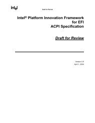
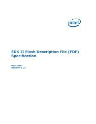
ln -s /home/usr/BaseTools /home/usr/Edk2Workspace/Conf/BaseToolsSource4. Run ". edksetup.sh BaseTools" under the workspace's directory to setsystem environment, such as WORKSPACE, EDK_TOOLS_PATH etc.5. Run "build -p UnixPkg\UnixPkg.dsc -a IA32 -t ELFGCC" to build Unixemulated platform.SecMain, the loader program for emulate environment, is built to the$(WORKSPACE)/Build/Unix/DEBUG_ELFGCC/IA32 directory.The Unix emulation is launched by executing SecMain.4.2.3 Duet platform4.2.3.1 OverviewUnlike Nt32 and Unix emulation platforms, a Duet platform provides a UEFI runtimeenvironment based on Legacy BIOS or UEFI implementation with legacy supportingactual machines.The Duet platform is started up by a boot loader from floppy/usb/hard disk. Duet'sboot loader collects following platform information:Memory description array from legacy E820 tableSMBIOS tableACPI RSD (Root System Description) tableMPS (MultiProcessor Specification) tableOther ACPI table.Because platform initialization has completed, a Duet platform does not need the PEIphase. The Duet boot loader transfers to DxeCore in by passing the collected platforminformation mentioned above.41 March, 2010
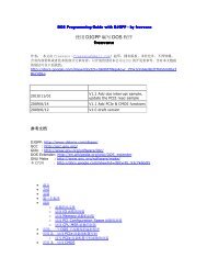
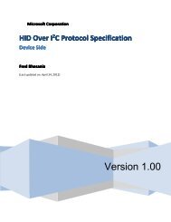
Legacy BIOS call "int 19" to load Duetboot sector to 0x7C00Duet boot sector find and loadDuet boot loaderDuet boot loader collects platforminformation and builds them into HOBDuet DxeIpl module load FV in boot diskand find DxeCore in loaded FVDuet boot loadertransfer to DXE phase.Figure 2 Startup flow for Duet environmentDuet platform requires the following packages, which can be downloaded fromhttp://edk2.svn.sourceforge.net/svnroot/edk2/trunk/edk2 .(Please refer to chapter 2.)MdePkgMdeModulePkgIntelFrameworkPkgIntelFrameworkModulePkgDuetPkgedkShellBinPkgEdkFatBinPkgBaseTools42 March, 2010
4.2.3.2 Build and Launch4.2.3.2.1 WindowsBuilding steps for Duet platform is the same as other actual platforms described inchapter 3.To launch a Duet platform, create a Duet boot disk and use the Duet boot disk to bootthe machine.CreateBootDisk.bat under the DuetPkg is used to create a bootable floppy/usb/harddisk from which the Duet platform is launched. The command line and options are:CreateBootDisk [usb|floppy|ide] DiskNumber [FAT12|FAT16|FAT32]If the boot media is floppy and the floppy disk number is a: in the hostmachine, run "CreateBootDisk floppy a: FAT12".If the boot media is usb and the usb disk number is e: in the host machine,run "CreateBootDisk usb e: [FAT16|FAT32]".If the boot media is a hard disk, it is not possible to create a bootable harddisk in the host machine directly. Instead, copy the boot and FV files to a usbdisk, then use EfiLdrImage tool shell application(This EFI tool is built from EDK project'sEdk\Sample\Platform\Duet\Tools\EfildrImage) to create boot sector in targethard disk in an UEFI environment.4.2.3.2.2 LinuxThe Duet platform also can be built with the Mingw tool chain under a Linuxenvironment.Steps for building Mingw tool chain1, Check out the build project from the svn repository:http://edk2.svn.sourceforge.net/svnroot/edk2/trunk/edk2/BaseTools2, Build the buildtools with command "make -f GNUmakefile"3, Enter “gcc” folder and run "mingw-gcc-install.py", which will download/build/installMinGw GCC and corresponding binutil automatically.4, Create soft symbol link to match the default path provided in tools_def.txt with thefollowing command:"ln -s /BaseTools/gcc/symlinks/ar /opt/tiano/i386-tiano-pe/i386-tianope/bin/ar""ln -s /BaseTools/gcc/symlinks/gcc /opt/tiano/i386-tiano-pe/i386-tianope/bin/gcc"43 March, 2010
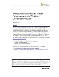
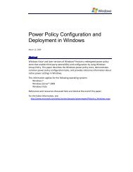
"ln -s /BaseTools/gcc/symlinks/ld /opt/tiano/i386-tiano-pe/i386-tianope/bin/ld"Note: File /Conf/tools_def.txt gives UNIXGCC tool chain to describethe build options for MinGW GCC. UNIXGCC tool chain is used to build Duetplatform.Steps for building Duet platform under UNIXGCC tool chain1, Open a Linux shell command and enter workspace folder2, Create soft link “BaseToolsSource” under /Conf folder to point therepository of build tools, such as:"ln –s /BaseTools /edk2/Conf/BaseToolsSource"3, Run ". edksetup.sh BaseTools" from workspace folder.4, Run "build –p DuetPkg/DuetPkg.dsc –a IA32 –t UNIXGCC"5, Run "DuetPkg/PostBuild.sh IA32"Steps for creating Duet boot floppy disk1, Inset a blank floppy2, Run "DuetPkg/CreateBootDisk.sh floppy /media/floppy0 /dev/fd0 FAT12"4.3 Shell EnvironmentThe EFI Shell is a simple, interactive environment that allows EFI device drivers to beloaded, EFI applications to be launched, and operating systems to be booted. Inaddition, the EFI Shell also provides a set of basic commands used to manage filesand the system environment variables etc.4.3.1 Launch ShellThe Shell, actually an EFI application, could be launched internally if the shell binary isbuilt in the firmware volume, or externally from a floppy/usb/hard disk.4.3.1.1 Launch Internal Shell1. After launching emulate environment; access the "Boot Manager" menu asfollows:44 March, 2010
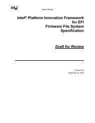
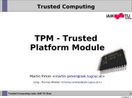
Figure 3 Select "Boot Manager" Menu2. If shell binary is built in a firmware volume, "EFI Internal Shell" item is listedas an boot option as follows:Figure 4 Select "EFI Internal Shell" from "Boot Manager"45 March, 2010
4.3.1.2 Launch External Shell1. Insert disk that contains a shell binary image or verify that the shell binaryimage is put at the directory that is emulated as a physical disk in anNt32/Duet platform.2. Boot the machine to the front page, select the "Boot Maintenance Manager"menu, and enter it.Figure 5 Select "Boot Maintenance Manager" from Front Page3. Select the "Boot From File" menu and enter it.46 March, 2010
Figure 6 Select "Boot From File" menu4. Select the disk that contains the shell binary in the device path list for disks.Figure 7 Select disk contains "EFI Shell" binary image47 March, 2010
5. In "File Explorer" menus, navigate the disk and find the "shell.efi" file.Figure 8 Select Shell.efi binary image6. Select "Shell.efi" in the file list and enter.4.3.2 Shell commandObtain the user manual and development manual for shell environment fromhttp://sourceforge.net/apps/mediawiki/tianocore/index.php?title=Efi-shell .Some useful internal shell commands are:Table 9 Internal shell commandsCommandDescriptionaliasattribcdclsconnectcopycpDisplays, creates, or deletes aliases in the EFI Shell.Displays or changes the attributes of files/directories.Displays or changes the current directory.Clears the standard output with a background color.Binds an EFI driver to a device and starts the driver.Copies one or more files/directories to another location.Copies one or more files/directories to another location.48 March, 2010
CommandDescriptiondatedeldhDisplays the current date or sets the date in the system.Deletes one or more files or directories.Displays the handles in the EFI environment.Displays a list of files and subdirectories.dirdisconnectdriversdrvcfgdrvdiagechoexithelp, ?loadlsmapmkdirmvreconnectresetrmsettimetouchtypeunloadvervolDisconnects one or more drivers from a device.Displays a list of drivers that follow the EFI Driver Model.Invokes the Driver Configuration Protocol.Invokes the Driver Diagnostics Protocol.Displays messages or turns command echoing on or off.Exits the EFI Shell.Displays the list of commands or verbose help of acommand.Loads EFI drivers.Displays a list of files and subdirectories.Displays or defines mappings.Creates one or more directories.Moves one or more files/directories to a destination.Disconnects a driver from a device and then connects itagain.Resets the system.Deletes one or more files or directories.Displays/creates/changes/deletes environment variables.Displays the current time or sets the time of the system.Updates the time with the current time.Displays the contents of a file.Unloads a protocol image.Displays the version information.Displays volume information of the file system.4.4 Enable Network on Nt32 platform<strong>EDKII</strong> provides UEFI network stack drivers in the MdeModulePkg\Universal\Networkfolder and brings the support of TCP/IP networking, with different driversimplementing different TCP/IP protocols.The hierarchal layering of the drivers is shown in the following image.49 March, 2010
Figure 9 EFI network driver layoutTo help develop networking applications, <strong>EDKII</strong> provides a SNPNT32Dxe driver inNt32Pkg\SnpNt32Dxe folder that implements the EFI_SIMPLE_NETWORK_PROTOCOLfor the NT32 platform. In conjunction with the UEFI network stack drivers this drivercan be used to develop and test networking applications on Windows® NT operatingsystem through the EDK’s NT32 platform emulation environment.The SNPNT32 driver depends on the WinPcap® (download it fromhttp://www.winpcap.org/install/default.htm) to transmit and receive packets on theWindows® system. To limit the number of symbols imported into the NT32 platform,SnpNt32 call the functions in the SnpNt32Io dynamic library to transmit/receivepackets. The SnpNt32Io library in turn consumes the service provided by WinPcap®.To enable/test network functionality, following steps should be taken:1) Install WinPcap application2) Download SnpNt32Io dynamic library source code fromhttp://sourceforge.net/apps/mediawiki/tianocore/index.php?title=Network-io , build itand generate SnpNt32Io.dll.3) Add following drivers into Nt32Pkg.dsc's [Components] sectionMdeModulePkg/Universal/Network/DpcDxe/DpcDxe.infMdeModulePkg/Universal/Network/ArpDxe/ArpDxe.infMdeModulePkg/Universal/Network/Dhcp4Dxe/Dhcp4Dxe.infMdeModulePkg/Universal/Network/Ip4ConfigDxe/Ip4ConfigDxe.infMdeModulePkg/Universal/Network/Ip4Dxe/Ip4Dxe.infMdeModulePkg/Universal/Network/MnpDxe/MnpDxe.inf50 March, 2010
MdeModulePkg/Universal/Network/Mtftp4Dxe/Mtftp4Dxe.infMdeModulePkg/Universal/Network/Tcp4Dxe/Tcp4Dxe.infMdeModulePkg/Universal/Network/Udp4Dxe/Udp4Dxe.infNt32Pkg/SnpNt32Dxe/SnpNt32Dxe.inf4) Also add them into [FD.Fv_Recovery] section in Nt32Pkg.fdf file:INF MdeModulePkg/Universal/Network/DpcDxe/DpcDxe.infINF MdeModulePkg/Universal/Network/ArpDxe/ArpDxe.infINF MdeModulePkg/Universal/Network/Dhcp4Dxe/Dhcp4Dxe.infINF MdeModulePkg/Universal/Network/Ip4ConfigDxe/Ip4ConfigDxe.infINF MdeModulePkg/Universal/Network/Ip4Dxe/Ip4Dxe.infINF MdeModulePkg/Universal/Network/MnpDxe/MnpDxe.infINF MdeModulePkg/Universal/Network/Mtftp4Dxe/Mtftp4Dxe.infINF MdeModulePkg/Universal/Network/Tcp4Dxe/Tcp4Dxe.infINF MdeModulePkg/Universal/Network/Udp4Dxe/Udp4Dxe.infINF Nt32Pkg/SnpNt32Dxe/SnpNt32Dxe.inf5) Build Nt32 platform.6) Copy SnpNt32Io.dll into Build/NT32/DEBUG_MYTOOLS/IA32/ directory.7) To test the Network functionality, launch Nt32 emulate and enter "Internal shell".The EFI application Ifconfig.efi and ping.efi are the commands to test networkfunctionality.4.5 Debugging in Emulation EnvironmentThere are two major debugging methods: print debug messages, and single step bybreak pointer. Printing debug messages is a popular debug method and very simple,but single step by break point may be different in each emulated platform.4.5.1 Print Debug MessageThe DebugLib library class defined in MdePkg provide useful interfaces such asDEBUG(), ASSERT(), ASSERT_EFI_ERROR() etc, which are easily used in a module'ssource code. For example:51 March, 2010
DEBUG ((EFI_D_ERROR, "This is error debug information"))DEBUG ((EFI_D_INFO, "This is help debug information"))EFI_D_ERROR, EFI_D_INFO indicates information level. To get more information leveldefinition, reference MdePkg\Include\Libarry\DebugLib.h. For example:#define DEBUG_INFO#define DEBUG_ERROR#define EFI_D_INFO#define EFI_D_ERROR0x00000040 // Verbose0x80000000 // ErrorDEBUG_INFODEBUG_ERRORPcdDebugPrintErrorLevel is used to control platform's debug information level. Itsvalue equals sum of all valid information level. It can be customized in a platform'sDSC file. For example, for a platform to enable debug and info message, the value ofPcdDebugPrintErrorLevel would be 0x80000040.Figure 10 Debug/Info message output4.5.2 Single Step Debugging in Nt32 Emulate PlatformPut "_asm int 3;" at the location to be debugged.When launching Nt32 emulate platform, Windows system default debugger islaunched automatically and stops at the location of "_asm int 3;"52 March, 2010
Figure 11 INT 3 is triggeredClick the "Cancel" button and system debuggers will be listed in following dialog.Select the "New instance of Visual Studio 2005" if the emulation is built by VisualStudio 2005.Figure 12 Select System Debugger53 March, 2010
Figure 13 Debugger is launched at first break point4.5.3 Single Step Debugging in Unix Emulate PlatformSingle step debugging in Unix emulates platforms is like the Nt32 emulated platform:1. Put "asm("int $3")" at the location to be debugged2. Enter $(WORKSPACE)/Build/Unix/DEBUG_ELFGCC/IA32/3. ELF execution SecMain module should be loaded by GDB program in Unix hostmachine. For example: "gdb SecMain".54 March, 2010