1004D3 and 1005E3 API Bottom Loading Coupler - The Meter and ...
1004D3 and 1005E3 API Bottom Loading Coupler - The Meter and ...
1004D3 and 1005E3 API Bottom Loading Coupler - The Meter and ...
- No tags were found...

You also want an ePaper? Increase the reach of your titles
YUMPU automatically turns print PDFs into web optimized ePapers that Google loves.
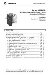
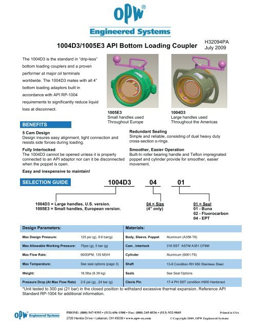
<strong>1004D3</strong>/<strong>1005E3</strong> <strong>API</strong> <strong>Bottom</strong> <strong>Loading</strong> <strong>Coupler</strong>H32094PAJuly 2009<strong>The</strong> <strong>1004D3</strong> is the st<strong>and</strong>ard in “drip-less”bottom loading couplers <strong>and</strong> a provenperformer at major oil terminalsworldwide. <strong>The</strong> <strong>1004D3</strong> mates with all 4”bottom loading adaptors built inaccordance with <strong>API</strong> RP-1004requirements to significantly reduce liquidloss at disconnect.BENEFITS<strong>1005E3</strong>Small h<strong>and</strong>les usedThroughout Europe5 Cam DesignDesign insures easy alignment, tight connection <strong>and</strong>resists side forces during loading.Fully Interlocked<strong>The</strong> <strong>1004D3</strong> cannot be opened unless it is properlyconnected to an <strong>API</strong> adaptor nor can it be disconnectedwhen the poppet is open.Easy <strong>and</strong> inexpensive to maintain!Redundant SealingSimple <strong>and</strong> reliable, consisting of dual heavy dutycross-section o-rings.Smoother, Easier OperationBuilt-In roller bearing h<strong>and</strong>le <strong>and</strong> Teflon impregnatedpoppet <strong>and</strong> cylinder provide for smoother, easiermovement.SELECTION GUIDE <strong>1004D3</strong> 04 01<strong>1004D3</strong>Large h<strong>and</strong>les usedThroughout the Americas<strong>1004D3</strong> = Large h<strong>and</strong>les, U.S. version.<strong>1005E3</strong> = Small h<strong>and</strong>les, European version.04 = Size(4” only)01 = Seal01 - Buna02 - Fluorocarbon04 - EPTDesign Parameters:Materials:Max Design Pressure: 125 psi (g), 8.6 bar(g) Body, Sleeve, Poppet Aluminum (A356-T6)Max Allowable Working Pressure: 75psi (g), 5 bar (g) Cam , Interlock 316 SST ASTM A351 CF8MMax Flow Rate: 600GPM, 135 M3/H Cylinder Aluminum (6061-T6)Max Temperature: See seal options (page 3) Shaft 13-8 Condition RH 950 Stainless Steel.Weight: 18.5lbs (8.39 kg) Seals See Seal OptionsPressure Drop (At Max Flow Rate) 2-5 psi (g), .24 bar (g) Clevis Pin 17-4 PH SST condition H900 Hardened.*Unit tested to 300 psi (21 bar) in the closed position to withst<strong>and</strong> excessive thermal expansion. Reference <strong>API</strong>St<strong>and</strong>ard RP-1004 for additional information.PHONE: (800) 547-9393 • (513) 696-1500 • Fax: (800) 245-8536 • (513) 932-9845Printed in USA2726 Henkle Drive • Lebanon, OH 45036 • www.opw-es.com © Copyright 2009, OPW Engineered Systems
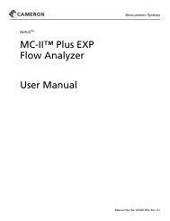
<strong>API</strong> <strong>Bottom</strong> <strong>Loading</strong> <strong>Coupler</strong><strong>1004D3</strong>/<strong>1005E3</strong># Description Qty Material Part #1 Body 1 Aluminum A356-T6, ASTM B26 Anodized. E20064AH2 Spirol Pin 7 Carbon Steel Zinc Plated. H31396M3 Interlock Spring 2 Carbon Steel Zinc Plated. H31743M4 Interlock 2 316 SST, ASTM A351 CF-8M. C20062M5 Cam Spring 5 18-8 SST. H06753M6 Cam 5 316 SST, ASTM A351 CF-8M. C20063M7 Wave Spring 1 17-7 PH SST, Condition H900 Hardened. H31091M8 Cylinder 1 Aluminum 6061-T6. C21283AH9 Cylinder O-Ring 1 See Seal Options Chart. - *10 Nose Seal 1 See seal Options Chart. - *11 Poppet 1 Aluminum A356-T6, ASTM B26, Anodized. D20069AH12 High Pressure Link 2 410 SST Hardened. H30552M13 Clevis Pin 2 17-4 PH SST, Condition H900 Hardened. H30610RE14 Washer 2 18-8 SST. H30206M15 E - Ring 2 SST H30554M16 Drive Link 1 316 SST, ASTM A351 CF-8M. C21255EW17 Sleeve 1 Aluminum A356-T6 ASTM B26 Anodized.E20013AH (<strong>1004D3</strong>)E20026AH (<strong>1005E3</strong>)18 Dust Seal 1 Felt H30214M19 Tube Spacer 1 316 SST. C21254RE20 H<strong>and</strong>le Shaft 1 13-8 Condition RH 950 Stainless Steel. C21290RE21 Stuff Box 1 316L ASTM A479 316. C20812RE22 Stuff Box O-Ring 2 See Seal Options Chart. - *23 Stuff Box O-Ring 1 See Seal Options Chart. - *24 Sleeve Bearing 1 97180 H32163M *25 Operating H<strong>and</strong>le 1 316 SST, ASTM A351 CF-8M. E20070EW26 Cam Follower 1 17-4 PH SST, Condition H900 Hardened. H32029RE27 Loctite As required Thread Locking Compound. TYPE 24228 3/8-24 Hex Nut 1 Carbon Steel Zinc Plated. H30220M29 Belleville Disc Spring 1 300 Series Stainless Steel H32158M30 Nut, Hex, SST, M10-1.5 1 SST H32111M31 ID Tag 1 0.12 Satin. -32 6-20 X 3/16” Thread Screw 4 Type B, Steel, Zinc plated H32149M* Items included in seal replacement kits (<strong>1004D3</strong>SRK)PHONE: (800) 547-9393 • (513) 696-1500 • Fax: (800) 245-8536 • (513) 932-9845Printed in USA2726 Henkle Drive • Lebanon, OH 45036 • www.opw-es.com © Copyright 2009, OPW Engineered Systems
<strong>API</strong> <strong>Bottom</strong> <strong>Loading</strong> <strong>Coupler</strong><strong>1004D3</strong>/<strong>1005E3</strong>IMPORTANT: OPW products should be used in compliance with applicable federal, state, provincial, <strong>and</strong> locallaws <strong>and</strong> regulations. Product selection should be based on physical specifications <strong>and</strong> limitations <strong>and</strong>compatibility with the environment <strong>and</strong> materials to be h<strong>and</strong>led. OPW MAKES NO WARRANTY OF FITNESSFOR A PARTICULAR USE. All illustrations <strong>and</strong> specifications in this literature are based on the latest productinformation available at the time of publication. OPW reserves the right to make changes at any time in prices,materials, specifications <strong>and</strong> models <strong>and</strong> to discontinue models without notice or obligation.SEAL OPTIONSSealMaterial<strong>Coupler</strong> Model #NoseSeal (10)Stuff BoxSeal (22)Stuff Box Seal(23)CylinderSeal(9)Buna N 1500<strong>1004D3</strong>-0401/<strong>1005E3</strong>-0401H30482M H20129M H31705M H30258MFluorocarbon<strong>1004D3</strong>-0402/<strong>1005E3</strong>-0402H30483M H20175M H31706M H30217MEPT E 692<strong>1004D3</strong>-0404/<strong>1005E3</strong>-0404H31957M H20176M H31707M H31956MConsult factory for additional seal options.Temp Rating-20°F - 250°F(-29°C - 121° C)-20°F - 400°F(-29°C - 204° C)-50°F - 225°F(-46°C - 107° C)SEAL REPLACEMENTKITSSeal Material Seal Replacement Kit Part #Buna N 1500 <strong>1004D3</strong>SRK-0401Fluorocarbon <strong>1004D3</strong>SRK-0402OPW <strong>1004D3</strong>SRK Seal Replacement Kitsinclude everything needed to change theseals in the <strong>1004D3</strong>/<strong>1005E3</strong> <strong>API</strong> coupler.Seal Replacement Kits are alwaysrecommended as spare parts. EPT E 692 <strong>1004D3</strong>SRK-0404Tools Needed• 11/16 inch or 17mm socket • 1-1/4 inch or 32mm deep reach socket.ASSEMBLY<strong>API</strong> coupler Installation PreparationsSafety precautionsWarning: Read & Underst<strong>and</strong> these instructions before starting installation.• <strong>Coupler</strong> to be used for its designated purpose only.• Local regulations for (un)loading must be followed at all times.• Product flow may result in static electricity; grounding of equipment is required.• Although the <strong>1004D3</strong>/<strong>1005E3</strong> designed for higher pressures, proper measures must be taken within thesystem to allow for thermal expansion.• OPW instructions must be followed for installation.Make sure to use adequate personal protection at all times during operation.Note: All images depict the <strong>1004D3</strong> (large h<strong>and</strong>les). <strong>The</strong> steps for <strong>1005E3</strong> coupler (small h<strong>and</strong>les) are thesame as <strong>1004D3</strong>Step 1 Step 2• Secure whateverdevice coupler willbe mounted to thee.g. loading arm.• S<strong>and</strong>wich gasketbetween coupler<strong>and</strong> load deviceflanges.Warning: Under pressure, poppet will cause h<strong>and</strong>le to rotate violently if not restrained.• Align coupler bolt holes withbolt holes on loading device.• Insert two bolts into thehighest bolt holes on theflange <strong>and</strong> h<strong>and</strong> tighten. Thisis to secure coupler, <strong>and</strong>prevent damage due tobending as the remainingbolts are installed.PHONE: (800) 547-9393 • (513) 696-1500 • Fax: (800) 245-8536 • (513) 932-9845Printed in USA2726 Henkle Drive • Lebanon, OH 45036 • www.opw-es.com © Copyright 2009, OPW Engineered Systems
<strong>API</strong> <strong>Bottom</strong> <strong>Loading</strong> <strong>Coupler</strong><strong>1004D3</strong>/<strong>1005E3</strong>Step 3• Connect the coupler to the adapter. Slide the sleeve fullyforward. Fully rotate the operating h<strong>and</strong>le <strong>and</strong> in the openposition, the operating h<strong>and</strong>le cam surface should prevent thesleeve from sliding back.MAINTENANCEConsider the following when servicing thecoupler:• When coupler is over pressurized, it must beinspected thoroughly.• After maintenance is performed, it must betested before the next use (see couplerTesting).• Periodical inspection (every 3 months) forleakages (especially with toxic or hazardousmediums).DISASSEMBLYINSTRUCTIONSStep 1: Dismantle <strong>API</strong> couplerAttention: Dismantling must be performed byauthorized <strong>and</strong> trained personnel only.Attention: <strong>The</strong> same risks <strong>and</strong> procedures ofinitial installation apply.• Maintenance must be performed by authorized personnel.• Periodical maintenance (once a year) is required according tothe maintenance instructions.• When any leakages are found, have seals replaced immediatelyto obtain a safe <strong>and</strong> correct use of the coupler. If leakagescontinue contact the OPW distributor or the OPW EngineeredSystems for consultation.Warning: Make sure what kind of medium has been or is beingloaded with this coupler, reading the manuals provided with thecoupler. When the medium is unclear, hazardous or toxic, one isobligated to clean the parts with the help of specialized personnel,companies or governments.Before dismantling coupler make some necessary preparationsFigure A• Securefrommovementthe devicethe coupleris attachedto (FigureA)Figure B• Make sure to use adequate personalprotection at all times during the operation.• Clear surrounding areas <strong>and</strong> shut off anyworking devices.• Make sure the surrounding area is clear fromobstacles.• Barricade surrounding area, so nounauthorized persons can access work floor.• Arrange necessary permits or paperwork withplant holder, owners or local authorities, beforetaking any actions.When the coupler is clean <strong>and</strong> dry <strong>and</strong> the necessary preparations have been made, the coupler can bedisassembled from the device it is attached to.PHONE: (800) 547-9393 • (513) 696-1500 • Fax: (800) 245-8536 • (513) 932-9845Printed in USA2726 Henkle Drive • Lebanon, OH 45036 • www.opw-es.com © Copyright 2009, OPW Engineered Systems
<strong>API</strong> <strong>Bottom</strong> <strong>Loading</strong> <strong>Coupler</strong><strong>1004D3</strong>/<strong>1005E3</strong>• With the corresponding loading arm secured from movement, loosen bolts mounting the coupler to the loadingarm. Support coupler while removing all bolts except top two. This is to prevent bending moments from causingdamage to the flanges <strong>and</strong> bolts (Figure B).• While supporting the loose coupler, remove the final two bolts. <strong>Coupler</strong> should fall away.• Remove gasket between both flanges.Step 2:Carefully, manuallydefeat the interlocks<strong>and</strong> slide the sleevefully forward. Fullyrotate the operatingh<strong>and</strong>le.Step 4:Remove the stuff box, seals <strong>and</strong> SleeveBearing. Remove the stuff box using the1 1/4 inch or 32mm deep reach socket.Step 6:Remove the poppet assembly, cylinder <strong>and</strong>cylinder wave spring.Step 3:Disassemble:Remove the 10mmnut <strong>and</strong> Bellevillewasher using the11/16 inch or 17mmsocket.Step 5:Remove the h<strong>and</strong>le shaft through thebody being careful to catch the tubespacer. Thoroughly clean the h<strong>and</strong>leshaft <strong>and</strong> tube spacer <strong>and</strong> inspect forStep 7:Remove the nose seal <strong>and</strong> O-ring from thecylinder. Thoroughly clean the cylinder <strong>and</strong>inspect for wear or damage.wear or damage. Step 8:Remove the 3 O-rings from the stuff box. Use theseal pick provided in the seal kit to remove theinternal O-ring. Note: <strong>The</strong> inner most stuff box O-ring may remain on the h<strong>and</strong>le shaft after thestuff box is removed. If required, remove thesleeve bearing from the stuff box. Thoroughlyclean the stuff box <strong>and</strong> inspect for wear ordamage.ASSEMBLY INSTRUCTIONSStep 1:Replace the nose seal <strong>and</strong> thecylinder O-ring. Lubricate theO-ring with light oil.Step 2:Replace the interior, exteriorO-rings <strong>and</strong> the sleevebearing in the stuff box.Lubricate the O-rings withlight oil.Step 3:Reinstall the cylinder wave spring <strong>and</strong> cylinder thenthe poppet assembly into the body.Important: Note orientation of high pressure links tothe through hole in the body.PHONE: (800) 547-9393 • (513) 696-1500 • Fax: (800) 245-8536 • (513) 932-9845Printed in USA2726 Henkle Drive • Lebanon, OH 45036 • www.opw-es.com © Copyright 2009, OPW Engineered Systems
<strong>API</strong> <strong>Bottom</strong> <strong>Loading</strong> <strong>Coupler</strong><strong>1004D3</strong>/<strong>1005E3</strong>Step 4:Slide the h<strong>and</strong>le shaft into thebody <strong>and</strong> through the drivelink. As the shaft just pokesthrough the drive link, installthe tube spacer. Rotate theshaft until the flats on the shaft<strong>and</strong> the drive link align <strong>and</strong>then push the shaft through<strong>and</strong> into the body.Step 5:Install the stuffbox using the 1-1/4 inch or 32mmdeep reachsocket. Tightenthe stuff boxfirmly into thebody.Step 6:Install the operating h<strong>and</strong>le,Belleville washer <strong>and</strong> 10mmnut. <strong>The</strong> Belleville washer iscone shaped. Install thiswasher such that the bottom ofthe cone is in contact with theoperating h<strong>and</strong>le. Tighten the10mm nut using the 11/16 inchor 17mm socket to compressthe washer as much aspossible.Step 7:Fully rotate the operating h<strong>and</strong>le to close thecoupler <strong>and</strong> slide the sleeve all the way back.Assembly CompleteWarning: With sleeve forward, operating h<strong>and</strong>le is unlocked <strong>and</strong> can rotate. Do not apply pressure to h<strong>and</strong>le unlesstrying to open valve. Use caution when working around h<strong>and</strong>le when system is under pressure. Once h<strong>and</strong>le startsmoving pressure can cause it to rotate violently.PHONE: (800) 547-9393 • (513) 696-1500 • Fax: (800) 245-8536 • (513) 932-9845Printed in USA2726 Henkle Drive • Lebanon, OH 45036 • www.opw-es.com © Copyright 2009, OPW Engineered Systems