DWFXTM Installation Guide.qxd - Actionair
DWFXTM Installation Guide.qxd - Actionair
DWFXTM Installation Guide.qxd - Actionair
- No tags were found...

You also want an ePaper? Increase the reach of your titles
YUMPU automatically turns print PDFs into web optimized ePapers that Google loves.
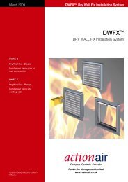
December 2006DWFX TM <strong>Installation</strong> <strong>Guide</strong>DWFX TM <strong>Installation</strong> <strong>Guide</strong>For Existing Dry Stud Partition Walls<strong>Installation</strong> <strong>Guide</strong>• Health and Safety• Equipment andMaterials• <strong>Installation</strong> ProcedureDampers Controls FancoilsSystem designed and builtin the UK.Ruskin Air Management Limitedww.ruskinuk.co.uk
DWFX TM <strong>Installation</strong> <strong>Guide</strong>Contents1 General 32 Health and Safety 33 Equipment 34 Materials 35 Measure the damper body overall size 36 Determine the finished hole size 37 Determine the hole to cut size 38 Example of hole to cut dimension calculation 39 Mark out the hole to be cut on the surface of the wall 310 Drill the four corners to project the rectangle on to the far side of the wall 311 Cut the top and bottom edges of the hole 312 Cut the vertical (side) edges of the hole 413 Remove the cut material to leave the hole 414 Tidy up all the edges of the hole 415 Frame out top and bottom edges of the hole 516 Frame out the sides of the hole 517 Finish the installation of the track and stud 618 Line the hole with board 619 Finish the hole 620 Drill clearance holes in the damper flange 721 Install the damper 722 Backfill with mineral fibre 723 Finish off with patress 7Appendix A 8A typical dry stud partition wall construction, as used in a damper test 81 General 82 Fixed Track and Stud 83 Additional construction studs 84 Board sections 85 Insulation 86 Finishing 87 Joints made good 82 www.actionair.co.uk
DWFX TM <strong>Installation</strong> <strong>Guide</strong>1 GeneralThis method of installation should only be employed with an<strong>Actionair</strong> damper that has the DWFX-F TMinstallation system2 Health and SafetyThis process must be undertaken by competent persons. Morethan one person may be required to ensure the safe handling oflarge dampers and sections of wall. Use must be made of accessequipment to ensure unsafe practices are not used to approachwalls or difficult access areas. Standard site PPE should be used(minimum steel toe cap boots, hard hat), together with anyprotective eyewear and masks, when drilling or cutting is beingundertaken. The latter should also be used when handing the wallconstruction materials, as defined by the material suppliers. Ifloud equipment is being used, hearing protection should be used.All waste materials should be collected and disposed of asdefined by the relevant supplier.3 EquipmentTape measure, pencil, straight edge, square, jigsaw (with fineblade), drill, screwdriver, tin snips, stanley knife, hammer/softmallet, rasp/surform, float9 Mark out the hole to be cut on the surface of the wallMark out the hole to be cut on one surface of the wall, using thecentre of the duct run as a datum. Check the diagonals of themarked out rectangle to ensure that it is square. It is advisable thatvertical edges do not coincide with a stud as this may be hard to cut4 MaterialsPlasterboard grabber screws, various lengths to suit, plasterboardthat was used in wall construction, plasterboard joint filler andfinish5 Measure the damper body overall sizeThis measurement should include the main damper frame andnot the peripheral flange. Care should be taken to include theshroud that the PTC interface will be pushed into, where this isfitted.6 Determine the finished hole sizeAdd 25mm ± 5mm to both the width and height dimensionmeasured above. This addition gives the hole into which thedamper will be placed and leaves an approximate gap all aroundthe damper and between the shroud casing and the hole ofapproximately 12.5mm7 Determine the hole to cut sizeThe hole that is to be cut into the wall has to be lined with onelayer of the board that was used in the building the wall to fullyprotect the wall construction. Add two thicknesses of board toeach of the finished hole width and height dimensions determinedabove.10 Drill the four corners to project the rectangle on to the farside of the wall.Drill through the wall at the four corners. The four resulting holesshould then be connected to mark out the hole on the oppositeside of the wall. Again the diagonals should be checked to confirmsquareness.8 Example of hole to cut dimension calculatione.g. Smoke/Shield Damper Nominal size 1000 x 1000Measure casing width ➱ 1045Add shroud dimension ➱ 30Add gap dimension ➱ 25Add 2 x typ. board thickness ➱ 25Gives hole to cut width = 1125Measure casing height ➱ 1070Add gap dimension ➱ 25Add 2 x typ. board thickness ➱ 25Gives hole to cut height = 112011 Cut the top and bottom edges of the holeIt is important to cut the horizontal (top and bottom) edges of thehole first, as this keeps the verticals rigid, whilst any studs are cutthrough. Do one side of the wall and then the other. Use a finejigsaw blade when cutting through any studs, to prevent “snagging”.www.actionair.co.uk3
DWFX TM <strong>Installation</strong> <strong>Guide</strong>12 Cut the vertical (side) edges of the holeThe vertical sides of the hole may now be cut.13 Remove the cut material to leave the holeThe waste wall material should now be removed. Trying toremove some of the board layers first, rather than trying toremove the slug as a whole may ease this.14 Tidy up all the edges of the holeTidy up all the edges of the hole to leave in as flat and clean astate as possible, so that it can be easily lined with fresh boardmaterial4 www.actionair.co.uk
DWFX TM <strong>Installation</strong> <strong>Guide</strong>15 Frame out top and bottom edges of the holeCut some track of the same type and dimension as that whichwas used in the wall construction. This should be slightly longerthan the hole top and bottom edge dimension (up to 25mmlonger). One piece is required for the bottom and one for the topof the hole. This track should be carefully be pushed in to gap toface of the cavity. It may be necessary to V-notch the ends of thetrack to be able to force it in at the ends.16 Frame out the sides of the holeCut some stud of the same type and dimension as that whichwas used in the wall construction. This should be the same asthe hole side edge dimension. One piece is required for eachside. This stud should be carefully be pushed in to gap to face ofthe cavity.www.actionair.co.uk5
DWFX TM <strong>Installation</strong> <strong>Guide</strong>17 Finish the installation of the track and studFinish the installation of the track and stud by fastening at300mm centres with grabber plasterboard screws of length tosuit the board thicknesses used.18 Line the hole with boardCut pieces of board to line all four sides of the hole. These shouldbe of a length to suit the width and then slightly reduced to fill inthe sides. The board should be cut to a width to suit the wallthickness. After installation any rough edges should be smoothedback. The board must be held in place with additional grabberplasterboard screws19 Finish the holeFinish the edges with plasterboard joint filler and finish.6 www.actionair.co.uk
DWFX TM <strong>Installation</strong> <strong>Guide</strong>20 Drill clearance holes in the damper flangeDrill clearance holes in the damper flange, marking out such thatany fasteners used will pass through the board materials andpenetrate the tracking and studding behind. Centres should beapproximately 150mm. This needs to be carefully calculated fromwall design, the gap around the damper and the thickness ofboard used to line the hole.22 Backfill with mineral fibreThe gap around the damper between it and the wall structuremust be in filled with mineral fibre, similar to that forming thestructure of the wall.21 Install the damperPlace the damper in the hole in the wall. Use some pieces ofplasterboard as shims to ensure that the damper is equallypositioned in the hole. Push the flange flush to the face of thewall. Fasten the flange to wall by carefully using plasterboardgrabber screws of such a length that a good fastening is madeback to the stud and track lining the hole.23 Finish off with patressMake good the joint with the wall by use of a patress, this has theadditional benefit of preventing leakage of the mineral wall infill.Grabber screws at 300 centres.www.actionair.co.uk7
DWFX TM <strong>Installation</strong> <strong>Guide</strong>Appendix AA typical dry stud partition wall construction, as used in a dampertest1 GeneralThe wall for a typical fire test is built with 3 fixed edges and one(vertical) unconstrained edge. The pictures below show how thewall used for the method of installation shown above wasconstructed.2 Fixed Track and StudA track was installed across the base of the wall and screweddown to the frame/floor. A stud was then secured up one walland screwed back to the wall. This was repeated with thetop/ceiling track.3 Additional construction studsLengths of stud were then cut to the height of the partition less15mm for expansion.4 Board sectionsOne side of the partition was then constructed by fixing boardsback to the studs, which were sited at 600mm centres. Theboards were fastened back to the stud and the tracks at 300mmcentres. A second layer was then added, with the boards equallystaggered with the first layer.6 FinishingThe partition was completed by adding a further two layers ofboard.5 InsulationInsulation was then added between the studs.7 Joints made goodThe joints are finished on the outside with plasterboard joint filler.8 www.actionair.co.uk
DWFX TM <strong>Installation</strong> <strong>Guide</strong>www.actionair.co.uk9
DWFX TM <strong>Installation</strong> <strong>Guide</strong>Ruskin Air Management LimitedSouth Street, Whitstable, KentCT5 3DU England.Tel: 01227 276100Fax: 01227 264262Email: sales@actionair.co.ukWebsite: www.actionair.co.ukBROCHURE PRODUCTION Geoff Strange MCSD LNNN00112