Stratos-Ex ⢠INSTALLER'S HANDBOOK
Stratos-Ex ⢠INSTALLER'S HANDBOOK
Stratos-Ex ⢠INSTALLER'S HANDBOOK
- No tags were found...

Create successful ePaper yourself
Turn your PDF publications into a flip-book with our unique Google optimized e-Paper software.
®Hazardous area aspirating smoke detectorInstaller’s Handbook LM80029 • Issue 2
pageIntroduction 3Indicators 5Inside the Enclosure 6Programming the Detector 8Design Limitations 20Installation 23Interfacing 30Event Log 35Commissioning 36Maintenance 38Troubleshooting 42Do’s and Don’ts 44<strong>Stratos</strong>-<strong>Ex</strong> Technical Data 45RELEASE NOTESRev. Date Revision History Prepared Approved1.0 14-06-07 Preliminary D. Elms CMLReproduction of this document is strictly prohibited unless written permission is obtained from AirSense Technology.In line with continuous product improvement, AirSense Technology reserves the right to modify or update specifications without notice.AirSense, <strong>Stratos</strong>, HSSD, Micra, ClassiFire and <strong>Stratos</strong>-Quadra are registered trademarks of AirSense Technology.<strong>Stratos</strong>-<strong>Ex</strong>, FastLearn, PipeCAD, LDD and SenseNET are trademarks of AirSense Technology.Copyright © 2008 AirSense Technology.<strong>Stratos</strong>-<strong>Ex</strong> • INSTALLER’S <strong>HANDBOOK</strong> • Iss. 2Page 2© AirSense Technology. 2008
Introduction<strong>Stratos</strong>-<strong>Ex</strong> is a highly sophisticated ‘next generation‘ of High Sensitivity AspiratingSmoke Detection product that has been designed to ensure that installation andcommissioning is as simple as possible, whilst optimising performance.<strong>Stratos</strong>-<strong>Ex</strong> incorporates a patented system of ‘Perceptive Artificial Intelligence‘ known asClassiFire ® , which allows the detector to initially configure and then to maintain itself atoptimum sensitivity. ClassiFire also monitors the detector chamber and dust separatorfor contamination, continually adjusting the appropriate operating parameters tocounteract the negative effects of such contamination.The <strong>Stratos</strong> ® range of detectors are unique in being able to provide a consistent levelof protection in a very wide range of environments by continuously making minoradjustments to sensitivity. Detectors from this range have proven their worth manytimes by detecting ‘difficult-to-detect‘ slow-growth electrical overload incipient fires in‘difficult‘ environments.This handbook gives information likely to be needed for most installations, but formore detailed information on subjects such as Fresh Air Referencing, please refer to thecomplete Technical Manual or System Design Guide.This equipment is Class III as defined in EN60950 (i.e., this equipment is designedto operate from Safety <strong>Ex</strong>tra Low Voltages and does not generate any hazardousvoltages).Key features:• Suitable for use with gas groups A, B and Hydrogen.• Light weight for easy and safe installation.• <strong>Ex</strong>ternal filter for maintenance without opening flameproof enclosureIf this equipment is part of a fire detection system, it should be supplied from anapproved power supply conforming to EN54-4.This symbol appears on the main board of the unit and indicates that the boardcontains static sensitive components. Suitable anti-static precautions must be takenwhen handling this component.LASER CLASS 1PRODUCTThis label is located on the laser chamber and signifies that the unit is a Class 1 Laserproduct as specified in IEC 60825-1. The unit incorporates a Class 3B embedded laserwhich must not be removed from the detector as retinal damage may result if the laserbeam enters the eye.This symbol indicates the Safety Earth stud. It should not be connected to 0V or signalearth.AirSense Technology has taken every care to ensure that <strong>Stratos</strong>-<strong>Ex</strong> is as simple to installas possible but in case of difficulty, please contact our Help Line to ensure trouble freeinstallation and operation.HELP LINE(+44) (0) 1438 751296AirSense Technology takes no responsibility for damage or injury occasioned as a resultof failing to install or operate and maintain the equipment in accordance with theseinstructions.<strong>Stratos</strong>-<strong>Ex</strong> • INSTALLER’S <strong>HANDBOOK</strong> • Iss. 2Page 3© AirSense Technology. 2008
<strong>Stratos</strong>-<strong>Ex</strong> is housed in a Groveley Engineering flameproof enclosure (certificate No.DEMKO028TEX131598) which is fitted with Knitmesh breathing devices (certficateNo. EPSILON06ATEX2138U) at the sample inlet and exhaust ports. The detectorfeatures dual high pressure aspirators to overcome the flow restriction of the Knitmeshbreathing devices and provide excellent air sampling performance. The use of twoaspirators provides an element of redundancy as the system will continue to sample inthe unlikely event of an aspirator failure.For ease of maintenance the air filter is mounted external to the main detector in aseparate stainless steel enclosure. The filter housing does not contain any electricalequipment and so it can be opened for filter replacement without compromising theflame-proof protection of the system.The light weight of <strong>Stratos</strong>-<strong>Ex</strong> (8.5kg) makes installation a simple and safe one-manoperation, with no special lifting equipment required.The networking capabilities of <strong>Stratos</strong>-<strong>Ex</strong> permit the use of remote displays andother standard accessories. Programming of a <strong>Stratos</strong>-<strong>Ex</strong> system can be undertakenusing the SenseNET system located in a safe area. As a member of the <strong>Stratos</strong> familyof detectors, <strong>Stratos</strong>-<strong>Ex</strong> is fully compatible with the Airsense SenseNet supervisorysoftware package.<strong>Stratos</strong>-<strong>Ex</strong> is ATEX approved and is rated at E<strong>Ex</strong> d IIB + H 2 T3 (Tamb -20C to +45C) orT2 (Tamb -20C to +60C).The explanation of this rating is as follows:ECarries a certificate in accordance with European harmonised standards<strong>Ex</strong><strong>Ex</strong>plosion-proof electrical equipmentdProtected by a flame-proof enclosureIIEquipment class II (For surface industries)BGas group B+ H 2 Hydrogen gasT3<strong>Ex</strong>ternal surface temperature will never exceed 200°C. See note above.This approval rating means that the system can be used in an area where an explosivemixture is likely to occur in normal operation (Zone 1) and where the gas which iscausing the risk is from gas group A, gas group B or is Hydrogen.<strong>Ex</strong>plosion-proof housing - <strong>Ex</strong> II 2 G E<strong>Ex</strong> d IIB+H2 T3 (Tamb -20°C to 45°C)<strong>Ex</strong> II 2 G E<strong>Ex</strong> d IIB+H2 T2 (Tamb -20°C to 60°C)Page 4© AirSense Technology. 2008<strong>Stratos</strong>-<strong>Ex</strong> • INSTALLER’S <strong>HANDBOOK</strong> • Iss. 2
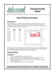
1. Indicators<strong>Ex</strong>haustInlet1 2 31. Fire indicator illuminates when the alarm level has been reached and theappropriate time delays have expired.2. Fault illuminates when the unit has a fault and a fault signal is being sent to thefire alarm panel or connected monitoring equipment.3. OK illuminates to show normal operation when there are no faults. The OK lampwill flash during the 15 minute FastLearn period when the detector is firstlearning its environment.DisplayretainingscrewsScrew downprotective coverLid lockingImportant Note:set screwRemoval of the! screw downInletIMPORTANTcover in mostapplicationswhere this productis installed willrequire a Hot Workpermit.<strong>Ex</strong>haustCable glands<strong>Stratos</strong>-<strong>Ex</strong> • INSTALLER’S <strong>HANDBOOK</strong> • Iss. 2Page 5© AirSense Technology. 2008
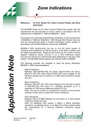
2. Inside theEnclosure2.01 Interior view16546323316 6511Detector Assembly RemovalThe display must first be removed (See section 1) in order to gain access to the fourdetector assembly retaining screws (5). When the four retaining screws are removedthe assembly may be withdrawn from the enclosure as shown above.If the detector assembly needs to be removed, care must be taken to avoid damagingthe airflow sensor cable. This must be disconnected from its connector adjacent to thedetector address switch before the detector assembly can be withdrawn.1. Removable terminal blocks (See section 2.02)2. Addressable Programmable Interface Card (APIC) connector (See section 7.3)3. APIC securing pillars4. Detector address switch (See section 7.01)5. Detector assembly securing points x 46. Display plate mounting pillar x 4Page 6© AirSense Technology. 2008<strong>Stratos</strong>-<strong>Ex</strong> • INSTALLER’S <strong>HANDBOOK</strong> • Iss. 2
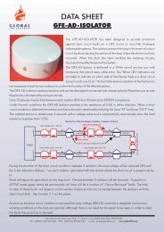
2.02 Detectorconnections910468OKFIREFAULT75 123Detector terminal connections1. Normally closed FAULT relay contact2. Normally open FIRE relay contacts3. Loop data to fire panel (See section 6.02.2 & 7.03)4. RS485 / SenseNET connections (See section 6.02.2 & 7.02.1)5. Power Supply (See section 6.02.1)6. IDC 26 way connector for APIC card (See section 7.03)Internal Connections7. Fire, Fault and OK display LED connections8. Aspirator drive connection9. Flow sensor connection10. RAM backup power jumper link<strong>Stratos</strong>-<strong>Ex</strong> • INSTALLER’S <strong>HANDBOOK</strong> • Iss. 2Page 7© AirSense Technology. 2008
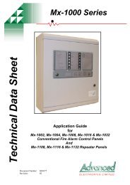
3. Programmingthe Detector<strong>Stratos</strong>-<strong>Ex</strong> may be programmed from a PC when connected to the detector via astandard 9-pin "null modem" (serial) lead connected to the serial port of the computerand the 9 way socket at the top of the front panel display. In order to do this, it isnecessary to install the remote control software onto the computer. A copy of theremote control software is contained on a CD supplied with each detector. Install thesoftware in accordance with the on-screen instructions.In instances where it is not permitted to energise the detector with the screw-on coverremoved, it is possible to program the detector remotely via a Command Module.!IMPORTANTImportant Note: Removal of the screw down cover in most applications where thisproduct is installed will require a Hot Work permit. Removal of the screw downprotective cover will affect the airflow monitoring.The programmable functions are all accessed though the “Options Detector settings”sub-menu or by clicking on the detector symbol in the remote software toolbar asindicated below.NB Initially there will be a prompt to enter the access code, whose default setting is ‘0102’.This window contains all the programmable functions for <strong>Stratos</strong>-<strong>Ex</strong>.To change one of the programmable functions, go to the relevant tab in the “Functionsettings” window, make the change and then click “OK”. This will save the change tothe detector’s internal memory.A list and explanation of the various functions is given overleaf, with the functionsgrouped by the tab under which they appear.Page 8© AirSense Technology. 2008<strong>Stratos</strong>-<strong>Ex</strong> • INSTALLER’S <strong>HANDBOOK</strong> • Iss. 2
3.01 Time and date - Time and Date tabIt is important that the time and date be set up correctly on the detector’s internalcalendar/clock because it uses this information to store events in the event log. (Seesection 8), “Event log” for more details. Unless specially ordered, units are suppliedwith the correct setting for UK time, and the clock is backed up with a rechargeablebattery. Later adjustments to the clock setting should not exceed ± 70 minutes unlessa FastLearn is initiated (See section 3.07), otherwise the day-night switching may notfunction correctly. (See section 3.11).3.02 Alarm levels - Alarm levels and delays tab, Level subgroupThe value set in the Fire, Pre-Alarm and Aux functions in the Level subgroupis the relatively scaled bargraph level at which the appropriate alarm is initiated onthe detector. The Fire 2 level assigns an absolutely scaled alarm level in percentageobscuration per metre.The Aux level is set by factory default at level 10 which means that this alarm will occurafter the Fire alarm. The default level settings for Pre-Alarm and Fire 1 are 6 and8 respectively. The default setting for Fire 2 is 20% obs/m.Note: That the <strong>Stratos</strong>-<strong>Ex</strong> has four alarm levels and a bargraph that are used internallyand transmitted via the SenseNET system. One alarm level and fault relays are providedon the standard <strong>Stratos</strong>-<strong>Ex</strong>. If more outputs are required then accessories are available toprovide them.3.03 Alarm delays - Alarm levels and delays tab, Delay subgroupThe alarm delay is the number of seconds that an alarm level has to be continuouslymaintained before the alarm is initiated. Each alarm level has a programmable delay ofbetween 0 and 90 seconds. The default delay for each alarm level is 5 seconds.3.04 ClassiFire override - Alarm levels and delays tabThis function is only available if the detector is fitted with an optional card which providesinputs. When this function is set to a value other than zero, the shorting together of the Input2 contacts on the option card will desensitise the detector by the specified percentage.3.05 ClassiFire Alarm factor - Alarm levels and delays tabThe detector sensitivity is set with this function, which will also affect the probabilityof nuisance alarms. 0 = high sensitivity, higher probability, 8 = low sensitivity, lowerprobability. The default alarm factor is 4.Note: The highest sensitivity setting (0) is suitable for clean, environmentally controlledareas where airborne pollutants are kept to an absolute minimum and the least smokedensity is desired to cause an alarm.Use of this setting in a smoky environment could lead to relatively frequent nuisancealarms due to the high level of normal variation of atmospheric smoke density. It istherefore important that the ClassiFire Alarm Factor chosen is suitable for the area to beprotected. When the appropriate alarm factor for the protected area has been set, nuisancealarms will be maintained at an absolute minimum with no need for detailed setup.<strong>Stratos</strong>-<strong>Ex</strong> • INSTALLER’S <strong>HANDBOOK</strong> • Iss. 2Page 9© AirSense Technology. 2008
The following table gives suggested settings of ClassiFire alarm setting.AlarmFactorSensitivityProbability of Nuisance Alarm0 <strong>Ex</strong>tremely High Once per year1 Very High Once per 5 years2 High Once per 10 years3 High Once per 50 years4 Medium Once per 1000 years5 Medium Once per 5,000 years6 Medium Once per 10,000 years7 Low Once per 20,000 years8 Low Once per 100,000 years3.06 LDD Enable - Alarm levels and delays tabWhen this function is ticked, Laser Dust Discrimination (LDD) increases the responsetime of the detector slightly, whilst greatly reducing the likelihood of nuisance alarmsdue to dust ingress. LDD may be disabled in very clean rooms for a slightly fasterresponse to smoke by setting this function to unticking the box. This function is enabledby default. NB: Disabling LDD is not recommended for areas other than very cleanenvironments, due to the increased probability of nuisance alarms in most other operatingenvironments.!IMPORTANT3.07 FastLearn enable - Alarm levels and delays tabIf the detector is in FastLearn mode, unticking this box will stop the FastLearn process.Using the function in this way is neither recommended nor supported by AirSenseTechnology.Ticking the box will start a FastLearn at any time. The green “OK” LED on the frontof the detector will flash for the 15 minutes that it takes for the FastLearn process tofinish, and will then change to constant illumination to indicate that the FastLearn iscomplete.Important Note: It will take a full 24 hours after the FastLearn for full sensitivity to bereached, unless Demonstration Mode has been initiated (See section 3.10, “Demo mode”).It is essential for proper sensitivity setting that the detector not be left in Demonstrationmode, and that it be allowed to complete the full 24-hour learning period. To cancel Demomode, tick this box or power down and restart the detector to initiate FastLearn mode.3.08 Auto FastLearn enable - Alarm levels and delays tabWhen enabled, this function ensures that if the detector is powered off for any reason(e.g. for maintenance or to be moved to a new area), a FastLearn is commencedautomatically on power-up. There may be occasions when it is desirable to powerdown the detector for short periods of time, and it is unlikely that ambient pollutionlevels will be changed upon power-up. Under these circumstances it may not bedesirable that the detector should go through a full 24 hour learning period. To thisend, this function can be unticked before power-down, whereupon it will return to theoriginal settings on power-up. This function is enabled by default.Page 10© AirSense Technology. 2008<strong>Stratos</strong>-<strong>Ex</strong> • INSTALLER’S <strong>HANDBOOK</strong> • Iss. 2
3.09 ClassiFire 3D - Alarm levels and delays tabIf this function is ticked, then the detector will ignore any pre-set time delays in theevent of an unacceptably rapid increase in smoke density, thereby minimising responsetime to 'rapid growth' fires. This function would normally only be used where thereare significant time delays programmed on the alarm levels. This function is disabledby default.!IMPORTANT3.10 Demo mode - Alarm levels and delays tabDemonstration mode is an operating mode whereby the normal full 24-hour learningperiod is shortened, so that the detector can reach high sensitivity after only the 15minute FastLearn period. This can be useful when initial smoke testing and othercommissioning needs to be carried out. To initiate Demo Mode tick this box and then"OK", while the detector is in FastLearn mode (i.e. the green light is flashing).Important Note: It must be understood that, since the alarm levels will be based solelyupon the sparse data gathered only during the 15 minute FastLearn period, there isan increased risk of nuisance alarms. For this reason, the detector should not be left inDemo mode for normal use.3.11 Day start / Night start - Day/Night switching tabThese values are the times to the nearest hour at which the day/night switching isdesired to take place. Entries are made in 24-hour format, e.g. 19 for 7pm. Day andnight switching may be desirable where the smoke density is expected to be differentbetween occupied and unoccupied conditions. ClassiFire automatically detects thechange in smoke level when the protected area is vacated and, if the time at which thisoccurs is within ± 70 minutes of the preset switchover time, it selects the previous nighttime histogram. Changes in time setting, e.g. changing to summer/daylight savingtime may be ignored as the detector also automatically adjust its day/night settingtimes. The default times for day and night start are 08:00 and 19:00 respectively.3.12 Disable Day / Night switching - Day/Night switching tabIf day/night switching is considered undesirable, the Disable day/nightswitching box may be ticked to leave the detector permanently in day mode.3.13 Remote functions - Alarm actions tab, Remote input subgroupThe following three functions are only applicable to those detectors fitted withoptional cards providing inputs. Before operation the appropriate function box mustbe ticked and the relevant pair of input terminals must be nominated (Input 1, 2 or3). The function will remain activated whilst the relevant pair of input terminals are'shorted' together.Remote IsolateIsolates the detector, no alarm signals are sent from the detector. For the durationthat the detector is isolated the fault relay will be activated. If the fault relay is notconnected to the main Fire Alarm Panel it is suggested that the relay be monitored tominimise the possibility of the detector being inadvertently left isolated. Ordinarily,a latching switch would be used for this application.<strong>Stratos</strong>-<strong>Ex</strong> • INSTALLER’S <strong>HANDBOOK</strong> • Iss. 2Page 11© AirSense Technology. 2008
Remote ResetResets any current alarm or fault condition. Ordinarily, a momentary, push-buttonswitch would be used for this application.Remote Day / Night SwitchingThe remote day night switching (as detailed in section 3.11) is manually overridden.Ordinarily a latching switch would be used for this application.!IMPORTANT!IMPORTANT3.14 Programmed Isolate - Alarm actions tabWhen this function is ticked, the detector will not generate alarms and will not indicate afault condition on any fire panel which is connected. This is only for use during detectormaintenance. The “Fault” light will be illuminated on the detector indicator panel. Ifaccidentally left in Programmed Isolate condition, the function will be automaticallydisabled after 7 days, re-arming the detector. This function is disabled by default.3.15 Latching alarms - Alarm actions tabWhen this function box is ticked, a Reset signal from a remotely located CommandModule, a PC running SenseNET software, or a remote reset switch is required to clearan alarm condition.If unticked, the alarm signal is extinguished as soon as the alarm condition ends. Thisis the factory default setting. Important Note: It is also possible to reset latched alarmsby connecting a PC equipped with Remote Control Software via the 9 pin serial portlocated under the screw down cover. In most areas this action would require a Hot Workpermit.!IMPORTANT3.16 Latching faults - Alarm actions tabWhen this function box is ticked it requires a Reset signal from a remotely locatedCommand Module, a PC running SenseNET software, or remote reset switch to cleara fault condition.If unticked, the fault signal is extinguished as soon as the condition ends. This isthe factory default setting. Important Note: It is also possible to reset latched faultsby connecting a PC equipped with Remote Control Software via the 9 pin serial portlocated under the screw down cover. In most areas this action would require a Hot Workpermit.3.17 Cascading alarms - Alarm actions tabWhen this function box is ticked the detector’s controller will not permit a Fire alarmto be generated before a Pre-alarm signal. This situation could otherwise occur if therewere a long time-delay set on Pre-Alarm and a short or non-existent delay on Fire Alarmlevel. This function is enabled by default.3.18 Device type - Device information tabThis function identifies the type of detector as <strong>Stratos</strong>-<strong>Ex</strong>. This is set in the Firmware andcannot be changed.3.19 Firmware version - Device information tabThis function is for display purposes only. It shows the version number of the fittedfirmware chip.Page 12© AirSense Technology. 2008<strong>Stratos</strong>-<strong>Ex</strong> • INSTALLER’S <strong>HANDBOOK</strong> • Iss. 2
3.20 Run-time hours - Device information tabThis function is for display purposes only. It shows the cumulative total number ofhours that the device has run (NB: this is not the time that has elapsed since last powerup,but the sum total of run time since the detector memory was last reset).3.21 Watchdog count - Device information tabThe Watchdog is a system incorporated in the controller electronics that restarts thecontroller in the event of a failure to function properly, which might be experiencedas a result of severe electrical noise. This counter shows the number of interruptionsrecorded. The details of each Watchdog reset can be found in the event log. (Seesection 8, 'Event log' for further details).3.22 Device text - Device information tabThis function is for display purposes when connected to a Command Module orcontrolling PC running SenseNET software. It can be modified for zonal or areaidentification. By default it shows <strong>Stratos</strong>-<strong>Ex</strong>.3.23 Reference detector - Referencing tabA <strong>Stratos</strong>-<strong>Ex</strong> detector may use another detector as a fresh air Reference as part ofthe product’s ability to compensate for the effect of external contamination to theprotected environment. This function is for setting the address of the detector whichwill be used as the Reference detector.To set a detector as a Reference detector on the Remote software, enter its address (asset by its internal DIP switch) into this function. This function is disabled by default.3.24 Reference enable - Referencing tabTicking this box enables a Reference detector, if one has previously been allocated inReference detector (See section 3.23) This function is disabled by default.3.25 Reference level - Referencing tabThe value set with this function is the percentage of reference detector signal whichwill be subtracted from the detector’s signal if a reference device has been allocated.The default value is 0.3.26 Reference back-off - Referencing tabThis value is the delay time in minutes between a build up of pollution being seen bythe Reference detector (if used) and the pollution being seen by the detector. Thedefault value is 15 minutes.3.27 Flow rate - Flow monitoring tabThis function is for display purposes only. It shows a value corresponding to the airflowrate through the detector.3.28 Flow high limit - Flow monitoring tabThis value is the level above which the airflow needs to increase to indicate a high flowfault condition. The most probable cause will be a damaged sampling pipe or changesin air conditioning systems.Flow low limit and Flow high limit parameters are automatically set up oninitial power-up, after the detector has established normal flow conditions.<strong>Stratos</strong>-<strong>Ex</strong> • INSTALLER’S <strong>HANDBOOK</strong> • Iss. 2Page 13© AirSense Technology. 2008
!IMPORTANT3.29 Flow low limit – Flow monitoring tabThis value is the level below which airflow needs to be reduced to indicate a faultreading. The most probable causes include: blocked or damaged sampling pipe (orfilter). Flow low limit and Flow high limit parameters are automatically setup on initial power-up, after the detector has established normal flow conditions.Important Note - The screwdown cover must be fitted during the flow setup process.3.30 Aspirator speed – Flow monitoring tabThis function has no current use on <strong>Stratos</strong>-<strong>Ex</strong> but is reserved for future expansionpurposes.3.31 Access code – Miscellaneous tabThis is the access code which is required to modify programmable parameters. Thedefault code is 0102. Once the appropriate code has been entered it may be changedto any four digit number to limit future unauthorised access.3.32 Chart recording rate – Miscellaneous tabThis function controls how frequently the detector and alarm level or flow ratesare stored in the <strong>Stratos</strong>-<strong>Ex</strong>’s internal chart recorder log. (See section 4.3, ‘Chartrecording’).The chart log recording rates are as follows.setting type storage intervaltime per divisionon chart log0 Detector output 1 second 10 seconds1 Detector output 5 seconds 50 seconds2 Detector output 12 seconds 2 minutes3 Detector output 30 seconds 5 minutes4 Detector output 1 minute 10 minutes5 Detector output 2 minutes 20 minutes6 Detector output 5 minutes 50 minutes7 Detector output 10 minutes 100 minutes8 Detector output 20 minutes 200 minutes9 Detector output 50 minutes 500 minutes10 flow recording 1 second 10 seconds11 flow recording 5 seconds 50 seconds12 flow recording 12 seconds 2 minutes13 flow recording 30 seconds 5 minutes14 flow recording 1 minute 10 minutes15 flow recording 2 minutes 20 minutes16 flow recording 5 minutes 50 minutes17 flow recording 10 minutes 100 minutes18 flow recording 20 minutes 200 minutes19 flow recording 50 minutes 500 minutesIn the above table, the grey section indicates flow rate recording, and the white sectionindicates detector and alarm level recording.At the slowest recording rate, one month of data can be recorded. The factory defaultsetting is 8.Page 14© AirSense Technology. 2008<strong>Stratos</strong>-<strong>Ex</strong> • INSTALLER’S <strong>HANDBOOK</strong> • Iss. 2
!IMPORTANT3.33 Separator condition – Miscellaneous tabThe value given at this function is the efficiency rating of the dust separator elementslocated in the remote dust separator enclosure (See section 10, “Maintenance”). Thisvalue is a percentage of the efficiency of a clean separator. When ClassiFire measuresthat the efficiency has decreased to 80% of that of a new filter, the Fault indicator LEDwill illuminate and the event log will show “Separator renew”.Important Note - When fitting new Dust Separator cartridges, a FastLearn must beinitiated (See section 3.07).3.34 Separator change date – Miscellaneous tabThis function defaults to “--“, which means that a separator fault will only appearwhen the efficiency decreases to 80% (See 3.33, “Separator condition”). However, adate may be entered into this function to allow for a scheduled maintenance period.The detector will then generate a separator fault at the planned time regardless ofthe condition of the separator, although degradation of the separator to below 80%efficiency before this date will override this. (See section 10, “Maintenance”).!IMPORTANT3.35 Factory default – Miscellaneous tabEnabling this function will reset each programmable function to the default valueindicated in the text, where a default setting is specified. It will also put the detectorinto FastLearn mode, regardless of whether or not Auto Fastlearn is enabled (Seesection 3.08). This ensures that the flow setups and alarm thresholds are optimised tothe detector’s working environment after resetting. Important Note - Where a ClassiFirealarm factor other than the default is required for the protected area, this will need tobe re-entered. Section 3.05 gives details of the ClassiFire alarm factors.4. Other remotesoftware features4.01 ResetIf latching alarms (See section 3.15) or latching faults (See section 3.16) are enabled,the relevant alarm or fault warnings will remain on the detector front panel LEDsand controlling unit until a reset is performed. If using SenseNET software, individualdetectors can be reset (refer to the SenseNET User Guide for details). In the remotesoftware, a Global reset is available which resets all detectors on the SenseNET loop,or a single stand-alone detector.To perform a reset, either select the menu options “Options Global Reset” or clickthe symbol indicated below.<strong>Stratos</strong>-<strong>Ex</strong> • INSTALLER’S <strong>HANDBOOK</strong> • Iss. 2Page 15© AirSense Technology. 2008
4.02 Histogram screenThe histogram screen shows various aspects of the detector function. To enter thehistogram screen, either select the menu options 'View Histogram viewer…' or clickthe symbol indicated below.The following screen appears:Smoke densityhistogramAlarm threshold flagsThere are two types of smoke density histogram; one shown in blue (the 'fast' histogram)which completely updates every 15 minutes, feeding information to the long-term'slow' histograms (which appear in yellow). These set the detector sensitivity based onthe ambient smoke conditions and it takes 24 hours for the two slow histograms (the'day' and the 'night' histograms) to complete their learning phase (See section 3.07).Detector sensitivity is based on the fast histogram during FastLearn and is thereafterbased on the currently active slow histogram.Page 16© AirSense Technology. 2008<strong>Stratos</strong>-<strong>Ex</strong> • INSTALLER’S <strong>HANDBOOK</strong> • Iss. 2
Sensitivity: This is a measure of the increase in smoke density required for the detectorto produce an alarm. The value is given in % obs/m (% obs/ft if US English selected).Mean: The current mean (average) value of smoke density, taken from the currently'active' histogram and given as a percentage of full scale deflection of the detectoroutput.Variance: The 'spread' of data in the currently active histogram showing the width ofthe distribution of readings.FastLearn: If the detector is currently in FastLearn mode, this will show the numberof minutes remaining in the FastLearn period. When this period has elapsed it willread “OFF” (Please note the product will require a full 24 hr period to achieve fullsensitivity).Alarm factor: This is the ClassiFire alarm factor (See section 3.05, 'ClassiFire Alarmfactor').Day/night: This indicates the currently active slow histogram.Alarm levels: These figures give the position of the various alarm flags in terms of apercentage of full scale deflection of the detector output.Detector output: This shows the real-time reading of smoke levels in terms of apercentage of full scale deflection.4.03 Chart recordingThe chart recording function shows how smoke density and the alarm level in theprotected area have varied over time. The chart may be downloaded to disk or printedout from a connected printer.To access the chart log, select the menu options 'View Chart recording…' or click thesymbol indicated below.<strong>Stratos</strong>-<strong>Ex</strong> • INSTALLER’S <strong>HANDBOOK</strong> • Iss. 2Page 17© AirSense Technology. 2008
The chart recording function may also be used to record how flow level through the<strong>Stratos</strong>-<strong>Ex</strong> detector varies with time. (See table at 3.32 for details).The following screen appears:The red trace is the current alarm level and the black trace is the detector output. Bymoving the cursor along the chart, the “Chart information” window (shown at thebottom left) updates to show the date and time, detector level and alarm level of therelevant period. The ‘File’ menu option in the chart recording window allows the chartrecording to be saved to disk or printed to a connected printer, and allows a previouslysaved chart recording to be loaded. Chart recording files have the extension “.rcw”.4.04 Open fileWhere a custom set of programmable function settings is commonly used, these mayconveniently be saved to, or loaded from disk. To open a detector function settings(.dfs) file, select the menu options “File Open” or click on the symbol indicated below.This function can also be used to examine saved event logs or chart recordings.Page 18© AirSense Technology. 2008<strong>Stratos</strong>-<strong>Ex</strong> • INSTALLER’S <strong>HANDBOOK</strong> • Iss. 2
Click on the “List files of type” drop-down box and select “Detector settings (*.dfs)”as indicated below.A list will appear of all detector settings files stored on the current drive. As aspecial case, if desiring to recall the factory default settings, there is a file named‘default.dfs’ in the ‘remote2k’ directory. Loading this file will reset the detector to thefactory default.<strong>Stratos</strong>-<strong>Ex</strong> • INSTALLER’S <strong>HANDBOOK</strong> • Iss. 2Page 19© AirSense Technology. 2008
5. DesignLimitations!IMPORTANT<strong>Stratos</strong>-<strong>Ex</strong> is intended to provide incipient fire detection. It is suitable for the rangeof applications typified by non-compartmentalised rooms, or items of electronic orelectromechanical equipment where it is desirable to achieve incipient fire reporting. Incompartmentalised rooms, each compartment would normally use individual <strong>Stratos</strong>-<strong>Ex</strong> detectors.<strong>Stratos</strong>-<strong>Ex</strong> is not intended to protect large areas, or to sample from areas where theremay be any difference in airflow rates or pressure differentials. Application of <strong>Stratos</strong>-<strong>Ex</strong>in these circumstances is not recommended. If detection in environments conformingto these descriptions is required, care must be taken to return sampled air to theprotected volume.Maximum recommended sampling pipe length is 50 metres in STILL AIR. In areas orapplications where the external airflow rate is greater than 1 metre per second, themaximum sampling pipe length is reduced to 25 metres.Although by no means essential, it must be recommended that if in doubt, PipeCAD sampling pipe modelling program be used to ensure that transit times, balance ofsuction and individual sampling point sensitivity are within desired limits.Sampling pipes must have capped ends. The end cap should be drilled with a holenormally between 4 and 10mm diameter and free from burrs. Sampling holes shouldnormally be 2.5 - 4mm diameter or as calculated by PipeCAD , and free from burrs.The pipe run should not have more than 10 holes (including the end cap hole).Pipe transit time from the furthest sampling hole from the detector must not exceed120 seconds. To prevent potentially dangerous build-up of static electricity, pipenetworks should use metallic pipe electrically bonded to Earth/Ground. It is stronglyrecommended that the smoke transit time from the furthest sampling hole be checkedduring commissioning tests.Page 20© AirSense Technology. 2008<strong>Stratos</strong>-<strong>Ex</strong> • INSTALLER’S <strong>HANDBOOK</strong> • Iss. 2
(a.) Locating thedetector outside thearea to be protectedEarth bonded metallicsampling pipeSampling holeFalse ceilingFilter<strong>Ex</strong>haustpipeInletpipe<strong>Stratos</strong>-<strong>Ex</strong>(b.) Locating thedetector within thearea to be protectedEarth bonded metallicsampling pipe<strong>Stratos</strong>-<strong>Ex</strong>SamplingholeFilterFalse ceiling<strong>Stratos</strong>-<strong>Ex</strong> • INSTALLER’S <strong>HANDBOOK</strong> • Iss. 2Page 21© AirSense Technology. 2008
5.01 System Design Simple designs with short sampling pipes produce the best results. Complex samplingpipe runs should be avoided. The use of ‘T’ branch-pipes is not recommended. Toassist in design and to verify system performance, it is advisable to use the AirSensePipeCAD sampling pipe modelling software.Always locate the sampling points in positions to which smoke may reasonablybe expected to travel. Do not expect ceiling-mounted sampling points to operatesatisfactorily if air flow from air-conditioning systems keeps the cool smoke from anincipient fire from reaching ceiling level. In this instance it is usually better to locatethe sampling pipe directly in the airflow (for example across the return air register ofan air conditioning unit).There is no substitute for carrying out smoke tests prior to installation of pipe work toindicate suitable sampling point location. Remember that cool smoke from an incipientfire does not behave in the same manner as hot smoke.5.02 SuggestedmaximumsamplingpipeworkconfigurationsEnd caps holes drilledto 7mm diameterSampling holes5 metre intervalsFilter<strong>Stratos</strong>-<strong>Ex</strong>Page 22© AirSense Technology. 2008<strong>Stratos</strong>-<strong>Ex</strong> • INSTALLER’S <strong>HANDBOOK</strong> • Iss. 2
6. InstallationBefore installing the detector, the local standards for hazardous areas and for installationof aspirating detection systems must be consulted, as these standards differ throughoutthe world. Specific advice for one country may not be applicable to another. Thefollowing is a brief set of guidelines on installing detectors.The detector will normally be mounted at a level where there is easy access to theunit for configuration and programming.Pipework should be metal and bonded to Earth/Ground to eliminate static electricitybuild-up. Selection of pipe is left to the site engineers, but the internal diametershould be between 20 and 25mm.The exhaust air from the unit must not be impeded in any way. If the unit ismounted in a different air pressure from where the air is being sampled (forexample an air duct), then a pipe must be taken from the exhaust port back to thesame air pressure zone as the sampling holes.Sampling holes should be free from burrs and swarf.All signal cables must be screened and must be of a suitable type. The specific typeof cable will normally depend upon the local fire and hazardous area regulations.The unit must not be placed in areas where either the temperature or humidity isoutside the specified operating range.The unit should not be placed in close proximity to any equipment expected togenerate high Radio Frequency levels (such as radio alarms) or units generatinghigh levels of electrical energy (such as large electric motors or generators).6.01 <strong>Stratos</strong>-<strong>Ex</strong>enclosureinstallationThe <strong>Stratos</strong>-<strong>Ex</strong> detector must be fixed to a solid location using the four mounting screwholes supplied.A template has been included at the back of this installer’s handbook to simplifymounting.Enclosure mountingpoints (arrowed)<strong>Ex</strong>haustInlet<strong>Stratos</strong>-<strong>Ex</strong> • INSTALLER’S <strong>HANDBOOK</strong> • Iss. 2Page 23© AirSense Technology. 2008
Standards and RequirementsThe installer should refer to the latest edition of the following standards beforeoperating in a Hazardous Area:EN 1127-1 <strong>Ex</strong>plosive Atmospheres – <strong>Ex</strong>plosion prevention and protection, basicconcepts and methodology.EN 60079-14 Electrical apparatus for explosive gas atmospheres Part 14: Electricalinstallations in hazardous areas (other than mines).EN 60079-17 Electrical apparatus for explosive gas atmospheres Part 17: Inspectionand maintenance of electrical installations in hazardous areas (other than mines).WarningsThe apparatus is ATEX CAT 2, only to be installed in Hazardous Area Zone 1 orHazardous Area Zone 2.The installer is to ensure that the equipment is located in areas that are known notto have adverse affect on the housing material.Do not modify the enclosure or component parts as this will compromise theapparatus certificate.The area in which the detector may be mounted must be in accordance withthe certification of the apparatus and in accordance with the standards of theappropriate authority in the country concerned.Local standards for the installation of aspirating detection systems must beconsulted.The detector should normally be mounted at a level where there is easy access tothe unit for configuration and programming.Pipework should be metal and bonded to Earth/Ground to eliminate static electricitybuild-up. Selection of pipe is left to the site engineers, but the internal diametershould be between 20 and 25mm.The exhaust air from the unit must not be impeded in any way. If the unit ismounted in a different air pressure from where the air is being sampled (forexample an air duct), then a pipe must be taken from the exhaust port back to thesame air pressure zone as the sampling holes.Sampling holes should be free from burrs and swarf.Page 24© AirSense Technology. 2008<strong>Stratos</strong>-<strong>Ex</strong> • INSTALLER’S <strong>HANDBOOK</strong> • Iss. 2
All signal cables must be screened and must be of a suitable type. The specific typeof cable will normally depend upon the local fire and hazardous area regulations.The unit must not be placed in areas where either the temperature or humidity isoutside the specified operating range.The unit should not be placed in close proximity to any equipment expected togenerate high Radio Frequency levels (such as radio alarms) or units generatinghigh levels of electrical energy (such as large electric motors or generators).Enclosure InstallationThe <strong>Stratos</strong>-<strong>Ex</strong> detector must be fixed to a solid location using the four fixing holes.A template has been included at the back of this manual to simplify mounting.<strong>Stratos</strong>-<strong>Ex</strong>, Fixing Hole Location<strong>Stratos</strong>-<strong>Ex</strong> • INSTALLER’S <strong>HANDBOOK</strong> • Iss. 2Page 25© AirSense Technology. 2008
6.01.2 Mechanical installation!IMPORTANTThe enclosure is connected to the installed sampling pipe-work and fixed to the wallor mounting surface using 4 bolts of a type appropriate to the mounting surface. It isessential that the sampling and exhaust pipes are properly screwed into the flame arrestors.Ensure that arrestors and EX approved adaptors are still properly engaged with aminimum of 5 threads engaged after sampling and exhaust pipes are fitted. ImportantNote - The screw down protective cover must be securely tightened and locked in positionby means of the lid locking set-screw (See section 1).6.02 Electrical installationThe <strong>Stratos</strong>-<strong>Ex</strong> detector is supplied with removable terminal blocks (See illustrations insection 2.02). These are simply removed from their sockets by lifting them up at rightangles to the circuit board. Take note of the orientation of each terminal block and itsfunction before removing it. It may also be beneficial to mark the connection wires withsuitable identification labels or coloured rings to aid in the connection process. NB: Allconnections should be made with the power turned off.To maintain the integrity of the flame proof enclosure it is important that all the cablesare properly terminated to compatible glands. Cable glands are not supplied, as cableselection is up to the site engineer. All cable glands holes to be fitted with E<strong>Ex</strong> d certifiedcable glands or E<strong>Ex</strong> d certified gland plugs. All enclosure threads to BS3643:1981class 6g & 6H with a minimum of 5 threads engaged. Cables to be fitted using glandmanufacturers installation instructions.Wiring!IMPORTANTBefore proceeding with the removal of the lid, it should be verified thatthe surrounding area is not explosive. In most applications, removal of thescrew-down cover will require a Hot Work permit.Remove the lid locking set screw (See section 1).Remove the lid by unscrewing anti-clockwise, place in a safe place to avoid damage.Remove the four screws, which securethe display on to the supporting pillars(arrowed).After disconnecting both the ribbon cableand LED connectors the display can thenbe removed to reveal the main detectorassembly.Page 26© AirSense Technology. 2008<strong>Stratos</strong>-<strong>Ex</strong> • INSTALLER’S <strong>HANDBOOK</strong> • Iss. 2
The cable glands are fitted and the cablescarefully threaded up the sides of thedetector assembly.The cables should then be cut to a suitablelength, this should be the shortest possiblelength that will comfortably allow the plugsto fit their respective sockets. The cablesshould be routed so as to avoid damagewhen the replacing the display and screwdowncover.The display LED connectors shouldthen be re-connected. The respectiveconnectors on the PCB are designatedGreen, Red and Amber, the colours relateto the colour LEDs on the Display; “OK”,“Fire” and “Fault” respectively. Theribbon cable should also be re-connectedto the socket designated “RS232” on thedetector assembly PCB.Re-fit the display using the correct fourscrews.<strong>Stratos</strong>-<strong>Ex</strong> • INSTALLER’S <strong>HANDBOOK</strong> • Iss. 2Page 27© AirSense Technology. 2008
6.02.1 Power supply connectionsThe power supply cable should be of 3-core screened type and should be led throughcable gland 1 or 2, leaving about 170mm of the cable extending from cable gland 1or 100mm from cable gland 2.The supplied ferrite bead should be threadedover the power cables before connecting to theterminal block.NB, note the orientation of the terminal block.Connect 0V and +24VDC to the “0V” and “24V”screw terminals respectively. Connect the earth tothe earth terminal.6.02.2 Signal connectionsRS485 (SenseNET terminals)APIC address terminalSignal connections should be made using cable suitable for the hazardous area andcompatible cable glands. If RS485 connection is used, the A+B signals should ideally betaken through twisted pair cable. The SCN terminal should be connected to the cablescreen if possible, otherwise a third conductor should be used.Signals and power should not normally be in the same cable, as electrical noise canjump between conductors.Page 28© AirSense Technology. 2008<strong>Stratos</strong>-<strong>Ex</strong> • INSTALLER’S <strong>HANDBOOK</strong> • Iss. 2
6.03 Final installationSlot the power and signal terminal blocks into the relevant sockets on the detectorPCB (they will only click fully home in the correct orientation), replace the front displayusing the four M3 pan-head screws provided and replace the enclosure lid. (See figs.1-3).!IMPORTANTImportant Note: The detector can only operate properly with the lid securely fitted.Fig. 1Fig. 2Fig. 3<strong>Stratos</strong>-<strong>Ex</strong> • INSTALLER’S <strong>HANDBOOK</strong> • Iss. 2Page 29© AirSense Technology. 2008
7. InterfacingBecause of the flexible nature of the <strong>Stratos</strong>-<strong>Ex</strong> ® detector and the many possibleconfigurations, there are many options for interfacing the detectors to the Fire Panel.Because of this, it is not possible to give a complete list of all interfacing methods butthe following pages will give details of the most common methods that are likely tobe used.7.01 Setting the detector addressIn order to identify itself to a PC or Command Module, each detector on a SenseNETnetwork needs to have a unique address ranging from 1 to 127. The detector addressis simply set on the red DIP switch SW1 at the top right of the opened detector on themain circuit board. The switch settings are 'on' for 1 and 'off' for 0, and the detectoraddress is set as a 7-bit binary code using switches 1-7. (Switch 8 is not used). Anexample is shown below.DILON12 3 4 5 6 7 8The address equates to 00100011 in binary, or (1 x 1) + (1 x 2) + (0 x 4) + (0 x 8) + (0x 16) + (1 x 32) + (0 x 64) = 35.The full range of available addresses and their relevant switch settings are in section7.01.2 for reference.Page 30© AirSense Technology. 2008<strong>Stratos</strong>-<strong>Ex</strong> • INSTALLER’S <strong>HANDBOOK</strong> • Iss. 2
7.01.2 Address tableWhen multiple detectors are used on a SenseNET bus, addresses chosen fordetectors must all be different.ADDRESS 1 2 3 4 5 6 7 81 1 0 0 0 0 0 0 02 0 1 0 0 0 0 0 03 1 1 0 0 0 0 0 04 0 0 1 0 0 0 0 05 1 0 1 0 0 0 0 06 0 1 1 0 0 0 0 07 1 1 1 0 0 0 0 08 0 0 0 1 0 0 0 09 1 0 0 1 0 0 0 010 0 1 0 1 0 0 0 011 1 1 0 1 0 0 0 012 0 0 1 1 0 0 0 013 1 0 1 1 0 0 0 014 0 1 1 1 0 0 0 015 1 1 1 1 0 0 0 016 0 0 0 0 1 0 0 017 1 0 0 0 1 0 0 018 0 1 0 0 1 0 0 019 1 1 0 0 1 0 0 020 0 0 1 0 1 0 0 021 1 0 1 0 1 0 0 022 0 1 1 0 1 0 0 023 1 1 1 0 1 0 0 024 0 0 0 1 1 0 0 025 1 0 0 1 1 0 0 026 0 1 0 1 1 0 0 027 1 1 0 1 1 0 0 028 0 0 1 1 1 0 0 029 1 0 1 1 1 0 0 030 0 1 1 1 1 0 0 031 1 1 1 1 1 0 0 032 0 0 0 0 0 1 0 033 1 0 0 0 0 1 0 034 0 1 0 0 0 1 0 035 1 1 0 0 0 1 0 036 0 0 1 0 0 1 0 037 1 0 1 0 0 1 0 038 0 1 1 0 0 1 0 039 1 1 1 0 0 1 0 040 0 0 0 1 0 1 0 041 1 0 0 1 0 1 0 042 0 1 0 1 0 1 0 043 1 1 0 1 0 1 0 044 0 0 1 1 0 1 0 045 1 0 1 1 0 1 0 046 0 1 1 1 0 1 0 047 1 1 1 1 0 1 0 048 0 0 0 0 1 1 0 049 1 0 0 0 1 1 0 050 0 1 0 0 1 1 0 051 1 1 0 0 1 1 0 052 0 0 1 0 1 1 0 053 1 0 1 0 1 1 0 054 0 1 1 0 1 1 0 055 1 1 1 0 1 1 0 056 0 0 0 1 1 1 0 057 1 0 0 1 1 1 0 058 0 1 0 1 1 1 0 059 1 1 0 1 1 1 0 060 0 0 1 1 1 1 0 061 1 0 1 1 1 1 0 062 0 1 1 1 1 1 0 063 1 1 1 1 1 1 0 064 0 0 0 0 0 0 1 065 1 0 0 0 0 0 1 066 0 1 0 0 0 0 1 067 1 1 0 0 0 0 1 068 0 0 1 0 0 0 1 069 1 0 1 0 0 0 1 070 0 1 1 0 0 0 1 071 1 1 1 0 0 0 1 072 0 0 0 1 0 0 1 073 1 0 0 1 0 0 1 074 0 1 0 1 0 0 1 075 1 1 0 1 0 0 1 076 0 0 1 1 0 0 1 077 1 0 1 1 0 0 1 078 0 1 1 1 0 0 1 079 1 1 1 1 0 0 1 080 0 0 0 0 1 0 1 081 1 0 0 0 1 0 1 082 0 1 0 0 1 0 1 083 1 1 0 0 1 0 1 084 0 0 1 0 1 0 1 085 1 0 1 0 1 0 1 086 0 1 1 0 1 0 1 087 1 1 1 0 1 0 1 088 0 0 0 1 1 0 1 089 1 0 0 1 1 0 1 090 0 1 0 1 1 0 1 091 1 1 0 1 1 0 1 092 0 0 1 1 1 0 1 093 1 0 1 1 1 0 1 094 0 1 1 1 1 0 1 095 1 1 1 1 1 0 1 096 0 0 0 0 0 1 1 097 1 0 0 0 0 1 1 098 0 1 0 0 0 1 1 099 1 1 0 0 0 1 1 0100 0 0 1 0 0 1 1 0101 1 0 1 0 0 1 1 0102 0 1 1 0 0 1 1 0103 1 1 1 0 0 1 1 0104 0 0 0 1 0 1 1 0105 1 0 0 1 0 1 1 0106 0 1 0 1 0 1 1 0107 1 1 0 1 0 1 1 0108 0 0 1 1 0 1 1 0109 1 0 1 1 0 1 1 0110 0 1 1 1 0 1 1 0111 1 1 1 1 0 1 1 0112 0 0 0 0 1 1 1 0113 1 0 0 0 1 1 1 0114 0 1 0 0 1 1 1 0115 1 1 0 0 1 1 1 0116 0 0 1 0 1 1 1 0117 1 0 1 0 1 1 1 0118 0 1 1 0 1 1 1 0119 1 1 1 0 1 1 1 0120 0 0 0 1 1 1 1 0121 1 0 0 1 1 1 1 0122 0 1 0 1 1 1 1 0123 1 1 0 1 1 1 1 0124 0 0 1 1 1 1 1 0125 1 0 1 1 1 1 1 0126 0 1 1 1 1 1 1 0127 1 1 1 1 1 1 1 0<strong>Stratos</strong>-<strong>Ex</strong> • INSTALLER’S <strong>HANDBOOK</strong> • Iss. 2Page 31© AirSense Technology. 2008
7.02 Connecting a <strong>Stratos</strong>-<strong>Ex</strong> to a SenseNET/RS485 detectornetworkRS485 1ARS485 1ARS485 1ARS485 1BRS485 1BRS485 1BSCRNSCREEN 1SCREEN 1RS485 2AAARS485 2ARS485 2ARS485 2BBBRS485 2BRS485 2BSCRNSCNSCNSCREEN 2SCREEN 2CommandModuleDetector 1(<strong>Stratos</strong>-<strong>Ex</strong>)Detector 2(<strong>Stratos</strong>-<strong>Ex</strong>)Detector 3(<strong>Stratos</strong>-HSSD)Detector 127(<strong>Stratos</strong>-HSSD)Up to 127 detectors may be linked in a single SenseNET bus, supporting a total lengthof cable of up to 1.2km. This can be extended with the use of RS485 repeaters. <strong>Stratos</strong>-HSSD detectors have built-in repeaters.In the above example, two <strong>Stratos</strong>-<strong>Ex</strong> detectors are linked into a 127-detector buswith a Command Module and a number of <strong>Stratos</strong>-HSSD detectors. It will be notedthat whereas the <strong>Stratos</strong>-HSSD units have two input / output buses (1A / 1B and 2A /2B), the <strong>Stratos</strong>-<strong>Ex</strong> has only a single such bus (A / B) and therefore each bus terminalhas an input and an output wire, compared with a single wire in each terminal in the<strong>Stratos</strong>-HSSD.For this reason, it may be easier to join the input and output wires for each bus andscreen connections together and to solder or crimp a single wire or connecting ferruleto each wire pair so that they are easier to fit into the screw terminals. If this is done itis recommended that bare wire joints be insulated to prevent possible shorting of thedata bus, which will cause a drop-out of data on the SenseNET bus.In the above example, there could be a total length of RS485 cable of up to 1.2kmbetween the Command Module and Detector 3, since these are all on a single bus.However, Detector 3 is a <strong>Stratos</strong>-HSSD which has a second communications bus(RS485 bus 2) and an RS485 repeater. This allows a further total of 1.2km of cable untilthe next <strong>Stratos</strong>-HSSD in the RS485 loop.In the above example, if detectors 3-126 (not shown) were all of the <strong>Stratos</strong>-<strong>Ex</strong> typethen the total length of wiring between detectors 3 and 127 would be limited to 1.2kmwithout an optional bus isolator board fitted. However, each additional <strong>Stratos</strong>-HSSDdetector wired up using both RS485 buses would allow an additional 1.2km of cablingto be added to the RS485 loop.Page 32© AirSense Technology. 2008<strong>Stratos</strong>-<strong>Ex</strong> • INSTALLER’S <strong>HANDBOOK</strong> • Iss. 2
7.03 Connecting <strong>Stratos</strong>-<strong>Ex</strong> to an addressable Fire PanelAn Addressable Protocol Interface Card (APIC) may be used to decode detectorinformation and to communicate this to a Fire Panel.The APIC is fitted to the four mounting studs on the <strong>Stratos</strong>-<strong>Ex</strong> PCB using the suppliedscrews as shown below:Preliminary draftThe connections to the Fire Panel are made using the BUS L1 and H1 (loop in, negativeand positive) and the BUS L2 and H2 (loop out, negative and positive) terminalconnectors shown in Section 6.02.2.The only settings that need to be made are on the APIC address switches. The start loopaddress Is entered on SW1 and the end loop address on SW2. In the case of an APICfitted to a single <strong>Stratos</strong>-<strong>Ex</strong> the start and end addresses will be the same.APICs are available for several different panel communications protocols.<strong>Stratos</strong>-<strong>Ex</strong> • INSTALLER’S <strong>HANDBOOK</strong> • Iss. 2Page 33© AirSense Technology. 2008
7.04 Connectingto a PCTo connect a single stand-alone detector to a PC, connect the PC‘s serial port directlyto the detector‘s 9-way RS232 port. Connections for this cable are shown below.!IMPORTANTImportant Note: Removal of the screw down cover in most applications where thisproduct is installed will require a Hot Work permit.9 pin female ‘D‘connector9 pin female ‘D‘connector2357832587To P.C.serial portSerial port connectionPage 34© AirSense Technology. 2008<strong>Stratos</strong>-<strong>Ex</strong> • INSTALLER’S <strong>HANDBOOK</strong> • Iss. 2
8. Event LogAn event is defined as• a change to any programmed function• a signal received from an external controller such as the remote software, APIC orSenseNET• a detector output level meeting or exceeding the Pre-Alarm, Aux, Fire 1 or Fire 2alarm thresholds• a fault condition such as a flow or separator fault• start of day / night operation• demonstration mode start / stop• FastLearn start / stop• Power on or offThe detector stores an internal log of the last 200 events, and this can either be viewedon a PC screen or downloaded to disc by use of the remote control software.When the event log is full (200 events are stored) and a new event occurs, the oldestevent in the log is deleted (First-In, First-Out).To download the event log, connect a PC to the detector serial port and run theremote software. Either select the menu options “View Event log” or click on theevent log symbol as indicated below.The following screen appears:<strong>Stratos</strong>-<strong>Ex</strong> • INSTALLER’S <strong>HANDBOOK</strong> • Iss. 2Page 35© AirSense Technology. 2008
This shows the time and date of each event stored in the log along with its generaldescription. The buttons at the bottom of the screen allow control over the input andoutput of the log.Open: opens a previously saved event log. Event logs have the file extension '.evt'.Save As: saves the current event log as a .evt file with a user defined name.Print: prints the event log to a connected printer.Filter: clicking on this option brings up the following screen:This allows the user to limit the information printed or viewed on the PC screen.For example the user might wish to concentrate on alarm events only. To do this,click on 'None', which unticks all boxes, and then on 'Alarms'. To tick all the boxes,tick 'All'.Any or all of the event categories may be selected or deselected as desired.9. CommissioningBefore commissioning the detector, the local standards of aspirating detection systemsmust be consulted. These standards differ throughout the world, and specific advicefor the market in one country may not be applicable to another.Commissioning strategy will initially depend upon the environment in which thedetector is installed. The test used in a clean environment would be different to thatused in a dirty environment.For clean areas, a widely accepted test is that given in British Standard BS6266, whichsimulates equipment overheating at a stage well before combustion. To perform thetest, electrically overload a two-metre length of PVC insulated wire of 10/0.1mm gaugefor one minute using an appropriate power supply. The detector should respond withintwo minutes from the end of the wire overload to give an indication.For areas with higher levels of background particulate matter, testing methodologymight be similar to that of standard point detectors, or agreed in advance with theclient.Page 36© AirSense Technology. 2008<strong>Stratos</strong>-<strong>Ex</strong> • INSTALLER’S <strong>HANDBOOK</strong> • Iss. 2
Aerosol smoke should not be used, as it leaves an oily residue which can adverselyaffect the detector chamber and the flame arrestors. All other methods of producingsmoke involve heat, so care must be taken and authority obtained before this is donein a hazardous area.9.01 CommissioningchecklistThe following brief checklist allows quick setup of the detector. This procedure will beadequate for most standard installations.!IMPORTANT1. Before powering up the detector, visually check all cabling and glands to ensurecorrect connection. If wire identification is not immediately clear (e.g. by use ofdifferent coloured wires or wire identification sleeves) an electrical check shouldbe made. Important Note - Any damage caused by mis-connection of the detectoris not covered by warranty.2. Power up the unit and connect to a PC and set the address switches on thedetector board (See section 7.01) and APIC board if applicable (See section7.03).3. Verify that the time and date are correct (See section 3.01)4. Set an appropriate ClassiFire Alarm Factor for the protected environment. Thedetector will perform a FastLearn for the new alarm factor. (See section 3.07)5. Whilst the detector is still in FastLearn mode set the detector into demonstrationmode (See section 3.10).6. If a PC is being used to program the detector, remove the serial lead from the portand securely tighten the screw-down protective cover, locking it in place with thelid-locking set-screw. NB: Air-flow faults should be expected at this stage, asthe air path is incomplete.7. Wait for the FastLearn to finish and the OK LED indicator to stopflashing. Perform any necessary smoke tests, ensuring that thedetector reacts appropriately and let the smoke fully dissipate.NB: Aerosol canister type synthetic smoke sources should not be used to testthe response of the detector as these may leave residue which could causedamage to the unit.8. Power down the detector and power back up, so that it enters another FastLearn,this time not putting the detector into Demonstration Mode. The detectorwill generate no alarms during the 15 minute FastLearn period, and after thisthe detector will operate at a reduced sensitivity for 24 hours whilst ClassiFireacclimatises to the protected environment and sets up appropriate day and nightsensitivity settings.<strong>Stratos</strong>-<strong>Ex</strong> • INSTALLER’S <strong>HANDBOOK</strong> • Iss. 2Page 37© AirSense Technology. 2008
10. Maintenance <strong>Stratos</strong>-<strong>Ex</strong> is a very low maintenance detection system. If required, external cleaningof the unit should be performed using a damp (not wet) cloth. Do not use solvents.The only part that may require field replacement during servicing is the dustseparator assembly. The dust Separator condition can be reviewed under theMiscellaneous tab of the remote software Function settings screen (Seesection 3.33, also shown below) which gives a percentage reading of dust separatorefficiency. When this level drops to 80% the detector will signal a fault and the dustseparator will need replacing. Alternatively a Separator change date may beentered under the Miscellaneous tab of the Function settings. On thedesignated date a 'Separator change' fault will be signalled, in this configurationa separator replacement can be made to coincide with other planned maintenanceof the Fire Alarm system. This feature would typically be used in particularly hostileenvironments where an increased frequency of separator changes is required.!IMPORTANTAll necessary safety precautions regarding the specific area should be implemented beforeproceeding further, if you are unsure of these please consult the site safety officer.To replace the filter, remove the front cover of the remote filter housing and pull thefilters out. Slide the replacement filters in so that the 'Direction of flow' arrow printedon the carton duplicates that shown on the diagram overleaf and replace the frontcover.As dust contained in the dust separators may expose maintenance personnel to a'nuisance dust' hazard as defined by the 'Control of Substances Hazardous to Health'(COSHH), it is strongly recommended that suitable masks and protective clothing beworn when changing filters. Used separators are not intended for re-use and should besafely disposed of.Page 38© AirSense Technology. 2008<strong>Stratos</strong>-<strong>Ex</strong> • INSTALLER’S <strong>HANDBOOK</strong> • Iss. 2
Important Note -After fitting new DustSeparator cartridges,a FastLearn must beinitiated(See section 3.07).From area to be protectedDust Separator FittedFLOWFLOWDust Separator Fitted<strong>Stratos</strong>-<strong>Ex</strong> • INSTALLER’S <strong>HANDBOOK</strong> • Iss. 2Page 39© AirSense Technology. 2008
10.01 DiagnosticsThe remote control software includes a diagnostic function which carries out a numberof checks to verify the correct functioning of the detector. A good time to run thesetests is as a part of planned maintenance. To call up diagnostic mode, select the menuoptions “View Diagnostics” or click on the symbol indicated below.The following message will then appear on the screen:The software will then scan the loop for up to 127 detectors. For a single detector, waituntil the first detector has been identified and the window indicates that it is scanningfor Detector 2, then press the Cancel button.The following window appears:Click on the list entry to highlight it and click on the “Diagnostics…” button. Thesoftware will then commence the system tests. During the “Aspirator and flow” test,the aspirator will suddenly slow down, but this is a normal part of the test and no causefor alarm.Page 40© AirSense Technology. 2008<strong>Stratos</strong>-<strong>Ex</strong> • INSTALLER’S <strong>HANDBOOK</strong> • Iss. 2
When the test has finished and no problems have been found, the following screenappears:If any problems were found during the diagnostic tests, the nature of the fault will beindicated in the “Status” column.Scan:Read Button:Relays:Save As:Print:Reads in the status of all connected detectors.This brings up a display of the detector output and flow rate whichupdates in real time.Brings up a screen allowing the function of the volt-free ‘Fire’ andFault LEDs to be tested with the aid of a continuity meter or othertester. The Fire relay contacts are open in normal operation and willclose on test. The Fault relay contacts operate on a ‘Fail-safe’ basis andare held closed in normal operation. They will therefore open on test.Saves the summary list of scanned detectors and their status as a text(.txt) file.Prints the summary list to a connected printer.<strong>Stratos</strong>-<strong>Ex</strong> • INSTALLER’S <strong>HANDBOOK</strong> • Iss. 2Page 41© AirSense Technology. 2008
11. Troubleshooting 11.01 Nuisance alarms occur too often• Check that the ClassiFire alarm factor setting is appropriate for the normalworking environment of the protected area. (See section 3.05).• Check that the detector is not in Demonstration mode. This can be ascertainedby viewing the event log (See section 8) and checking that the entryDemo mode has a higher log entry number than the most recentFastLearn start and FastLearn end entries. Remember that the logentries are in reverse order, with the most recent entries appearing first.If the log shows that Demonstration mode was invoked during the last FastLearnperiod, start a new FastLearn and allow it to complete its 24-hour cycle. (Seesection 3.07)• From the event log (See section 8), check that 24 hours have elapsed since thelast FastLearn end entry.• Check that day-night switchover times are appropriately set to reflect active andnon-active periods (See section 3.11).11.02 Elevated smoke levels do not generate alarms• Check that detector is not Isolated or in FastLearn (if Isolated, the Fault light willbe illuminated)• Check that the detector sampling points are in the smoke stream• Check that the correct ClassiFire alarm setting has been set (See section 3.05)• Check that the detector has either had a 24 hour learning period or that it hasbeen placed in Demonstration Mode11.03 Low mean output• Check that the filter does not require changing (See section 10) and thatthe filter chamber is clean. The chamber may become clogged when, forexample, heavy building activity has occurred near the sampling pipes.11.04 Detector sensitivity varies over time• There are many reasons why smoke densities may vary, and the ClassiFire systemautomatically compensates for this in order to reduce the likelihood of nuisancealarms due to normal variations in background smoke density, within limits set bythe ClassiFire alarm factor. This is a normal part of the detector‘s working.Page 42© AirSense Technology. 2008<strong>Stratos</strong>-<strong>Ex</strong> • INSTALLER’S <strong>HANDBOOK</strong> • Iss. 2
11.05 Flow fault errors• These occur when the airflow rate into the detector is outside the pre-programmedlimits. As the detector ‘learns‘ the flow setup from the initial installation, thisusually means that there has been some change in conditions. A Flow high faultmay indicate that a sampling pipe is damaged, and a Flow low fault may indicatethat the pipe or filter has been blocked.11.05.1 'Low flow' error messages• Check that the pipe or filter is not blocked.• Check that the low flow fault threshold is not set too high (See section 3.29).11.05.2 'High flow' error messages• Check that the pipe is screwed home into the flame arrestor and is not broken orcracked.• Check that installed pipe-work is fitted with an end-cap. AirSense TechnologyPipeCAD pipe modelling software prompts the use of appropriate end-caps.Open bore pipes are not recommended.• Check that the high flow fault threshold is not set too low (See section 3.28).<strong>Stratos</strong>-<strong>Ex</strong> • INSTALLER’S <strong>HANDBOOK</strong> • Iss. 2Page 43© AirSense Technology. 2008
12. Do’s and Don’ts DOEnsure that the ClassiFire alarm factor is appropriately set.Ensure that cables are correctly connected before powering up by use of cableidentifiers or electrical continuity checks. Incorrect connection could damage thedetector.Ensure that cable of an appropriate approved type is used for interconnection.Place sampling points so that the detector will be able to detect smoke at theearliest opportunity.Ensure that the detector exhaust is in an area with the same atmospheric pressureas the sampling pipes, either by placing the detector physically in the protectedarea or by leading a pipe from the detector exhaust to the protected area.Ensure that the environment of the protected area is within the environmentaloperating parameters of the detector (temperature -10 to +60°C, humidity0-90%, non-condensing). Set the Detector Address Switches correctly when usedin a network.Set the detector address switches correctly if the detector is part of a network.Ensure that all hazardous area safety rules are followed and correct permits to workobtained.DON’TRemove or connect boards when the detector is powered up.Connect internal 0 volt terminals to local earth.Attempt to re-use dust separator cartridges once removed.Attempt to adjust or alter detector settings other than via the user-programmablefunctions. In particular, the setting up of the laser is a precision task, and onceset up the potentiometers should be left alone. If it is suspected that the laseralignment has shifted (e.g. after dropping the detector), it should be returned toAirSense for recalibration.Place the detector near high power RF sources.Test the response of the detector using aerosol canister synthetic smoke.Page 44© AirSense Technology. 2008<strong>Stratos</strong>-<strong>Ex</strong> • INSTALLER’S <strong>HANDBOOK</strong> • Iss. 2
13. <strong>Stratos</strong>-<strong>Ex</strong>Technical DataSELV rating (EN 60950)Supply Voltage<strong>Ex</strong>plosion-proof housingSize (mm) excluding cable glandsCable entriesWeightHousing materialOperating temperature rangeOperating humidity rangeSensitivity range (%Obs/m)Maximum sensitivity resolutionDetection principleClass III21.6V - 26.4V DCPSU Type: conforming to EN 54-4Electrical safety complies with BS EN610190-1II 2 G E<strong>Ex</strong> d IIB+H2 T3(Tamb -20°C to 45°C)II 2 G E<strong>Ex</strong> d IIB+H2 T2(Tamb -20°C to 60°C)400W x 200H x 180Dinc. breathing devicesUp to 4 x M208.5kgAluminium LM25Stainless Steel (ASTM 316) - option0 to +38°C (UL268)–10 to +60°C (CEA4022)0 - 90% Non CondensingBS EN 61010-1 Pollution degree 1BS EN 61010-1 Installation Cat. IIMin = 25% Max = 0.03% FSD0.0015 % obs/mLaser light scattering mass detectionParticle sensitivity range 0.0003µm to 10µmCurrent consumption 0.65ARelay contact rating*Maximum sampling pipe lengthSampling pipe inlets 1Sampling pipe internal diameterAlarm levelsChamber service intervalsDust separator replacement intervalsProgrammingData bus cableData bus lengthIP rating10VA (30V max. or 0.5A max.)50m20 - 25mm4 (Fire 2, Fire 1, Pre-Alarm and Aux)1 relay as standard, others availableGreater than 8 years (depending onenvironment)Greater than 2 years (depending onenvironment)PC via RS232/RS485RS485 data cable1.2 kmIP50*Devices, such as local sounders and beacons can demand high in-rush currents,which may damage the relays. If relays are used to drive the device directly, a suitable47 ohm current-limiting resistor should be placed in series with the load.NB This equipment is only to be used in accordance with this specification. Failure tooperate the equipment as specified may cause damage to the unit.<strong>Stratos</strong>-<strong>Ex</strong> • INSTALLER’S <strong>HANDBOOK</strong> • Iss. 2Page 45© AirSense Technology. 2008
Certification andStandardsThe <strong>Stratos</strong>-<strong>Ex</strong> series has been certified according to:ATEX Directive 94/9/EC and the requirements laid down by the following standards:EN 50014: 1997 incl A1 + A2EN 50018: 2000 incl A1Electrical apparatus for potentially explosiveatmospheres.General requirements.Electrical apparatus for potentially explosiveatmospheres.Flame-proof enclosure ‘d’Certificates• ATEX Certificate: EPSILON 06 ATEX 2074 (<strong>Stratos</strong>-<strong>Ex</strong>)• ATEX Certificate: EPSILON 06 ATEX 2138U (Knitmesh Arrester)• ATEX Certificate: DEMKO 02 ATEX 133173U (GD-JB-8000 Flameproof Enclosure)Product identification label<strong>Stratos</strong>-<strong>Ex</strong> Identification labelPage 46© AirSense Technology. 2008<strong>Stratos</strong>-<strong>Ex</strong> • INSTALLER’S <strong>HANDBOOK</strong> • Iss. 2
<strong>Stratos</strong>-<strong>Ex</strong> outline dimensions (mm)<strong>Stratos</strong>-<strong>Ex</strong> • INSTALLER’S <strong>HANDBOOK</strong> • Iss. 2Page 47© AirSense Technology. 2008
<strong>Stratos</strong>-<strong>Ex</strong> TemplateNB: Print this page 100% size, and not ‘shrink over sized page’, pdf defaultCable Entry 3 & 412mm dia. holesEXHAUSTINLETCable Entry 1 & 2<strong>Stratos</strong>-<strong>Ex</strong> • INSTALLER’S <strong>HANDBOOK</strong> • Iss. 2Page 48© AirSense Technology. 2008
TECHNOLOGYA UTC Fire & Security Company1 Caxton Place • Caxton Way • Stevenage • Herts • SG1 2UG • UKTel: +44(0)1438 751296 • Fax: +44(0)1438 729137e-mail: sales@airsense.co.uk • www.airsensetechnology.comAirSense Technology - A division of Kidde Products Ltd.Registered office: Mathisen Way, Colnbrook, Slough, Berkshire, SL3 0HB, UK.Registered in England No: 4622271