DEIF A/S
DEIF A/S
DEIF A/S

Create successful ePaper yourself
Turn your PDF publications into a flip-book with our unique Google optimized e-Paper software.
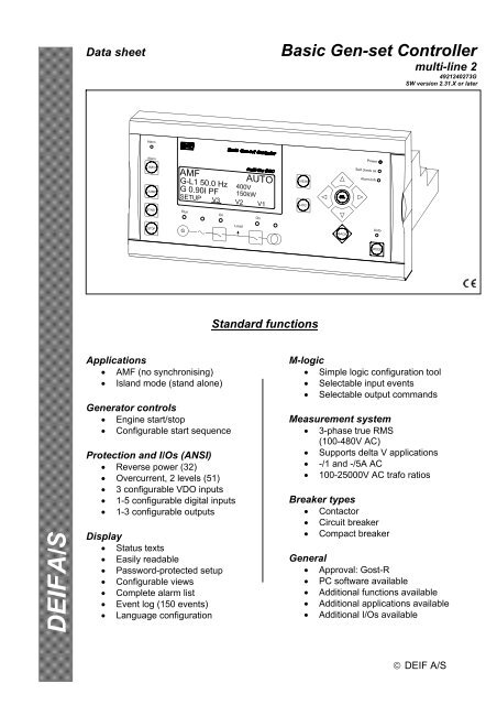
Data sheetBasic Gen-set Controllermulti-line 24921240273GSW version 2.31.X or laterStandard functions<strong>DEIF</strong> A/SApplications• AMF (no synchronising)• Island mode (stand alone)Generator controls• Engine start/stop• Configurable start sequenceProtection and I/Os (ANSI)• Reverse power (32)• Overcurrent, 2 levels (51)• 3 configurable VDO inputs• 1-5 configurable digital inputs• 1-3 configurable outputsDisplay• Status texts• Easily readable• Password-protected setup• Configurable views• Complete alarm list• Event log (150 events)• Language configurationM-logic• Simple logic configuration tool• Selectable input events• Selectable output commandsMeasurement system• 3-phase true RMS(100-480V AC)• Supports delta V applications• -/1 and -/5A AC• 100-25000V AC trafo ratiosBreaker types• Contactor• Circuit breaker• Compact breakerGeneral• Approval: Gost-R• PC software available• Additional functions available• Additional applications available• Additional I/Os available© <strong>DEIF</strong> A/S
Data sheetApplicationThe Basic Gen-set Controller is a microprocessorbasedcontrol unit containing all necessary functions forcontrol and protection of a gen-set and control of mainsand generator breaker. The standard control functionsinclude start and stop sequences for the engine, butregulation control is also possible. The BGC contains allnecessary 3-phase measuring circuits and all valuesand alarms are presented on the LCD display.The BGC is a compact all-in-one unit designed for thefollowing standard and optional applications:Standard applications: (no synchronising)1. Automatic mains failure (no back sync.)2. Island operationOptional applications: (synchronising)3. Multiple gen-sets, load sharing4. Peak shaving5. Fixed power to mains6. Automatic mains failure (back sync.)7. Load take overThe optional applications require governor/AVR controlfor parallel operation. (option G2 or G3).The generator and mains breaker types can beconfigured to be either a circuit breaker, a contactor orthe compact breaker which requires a signal to resetthe breaker from tripped to open position.Basic Gen-set ControllerGovernor and AVR controlSpeed governor control and automatic voltageregulation are optional functions and can be analogueor digital. (Both digital AVR + GOV outputs requires atotal of 4 relay outputs. Note that 3-13 relays areavailable depending on options and breaker selection.SetupSetup is easily done via a menu structure in the display(password protected, 3 levels) or via the RJ45/RS232PC connection and the multi-line 2 Windows ® based PCutility software. The PC interface box needed for thisoperation is optional equipment for the BGC. The utilitysoftware offers additional features such as monitoringof all relevant information during commissioning, savingand downloading of settings and downloading ofsoftware updates.OptionsIn order to perfectly match the product solution tospecific applications, the functionality of the BGC canbe equipped with a number of available options. Theoptions selected by the customer will be integrated inthe standard BGC hereby securing the same userinterface unaffected by whether the application needs ahighly complex or a more basic gen-set controller.Display variantsTwo display variants are available for the BGC unit.The unit is normally supplied with the AMF folio.AMF folioConfigurable inputs/outputs:The BGC is supplied with a standard number of inputsand outputs that can be used for control and/orprotection purposes. The number of configurable I/Osdepends on the used breaker type.The table only shows available I/Os for the standardunit (no hardware options are selected.) This meansthat additional I/Os can be selected (please refer to theoption list for more).PCB CircuitCompactContactorI/ObreakerbreakerMPU (Tacho) 1 1 1Digital inputs 9 (5) 9 (7) 9 (5)VDO 3 3 3Relay outputs 9 (1) 9 (3) 9 (1)If the unit is used in island applications, the island foliois selectable (Specify option Y1).Island folioThe number in parenthesis indicates the numberof user configurable digital inputs/relayoutputs.(Horn output, start/stop functionality andbreaker handling occupies the I/Os not freelyconfigurable).Additional I/Os can be selected.Example: BGC - M13.2 - M14.3 gives anadditional 7 digital inputs/4 digital outputs.Please see the option list and hardwareoverview in this data sheet.<strong>DEIF</strong> A/S Page 2 of 10
Data sheetBasic Gen-set ControllerSingle line application diagramsStandardAutomatic mains failure (no back sync.) (1)Island operation (2)33<strong>DEIF</strong> A/S Page 3 of 10
Data sheetBasic Gen-set ControllerOptionalMultiple gen-sets, load sharing (3)Peak shaving, load take over (4/7)3333Fixed power to mains (5)Automatic mains failure (back sync.) (6)33<strong>DEIF</strong> A/S Page 4 of 10
Data sheetBasic Gen-set ControllerAvailable optionsOption slot #4 is allocated to options G2 and G3 only. The two remaining slots (#2 and #3) can hold amaximum of two hardware options per unit.Option Description Type NoteALoss of mains protection packageBCDA1 Over- and undervoltage (generator and busbar/mains) (27/59)Over- and underfrequency (generator and busbar/mains) (81)Vector jump (78)df/dt (ROCOF) (81)A2 Over- and undervoltage (generator and busbar/mains) (27/59)Over- and underfrequency (generator and busbar/mains) (81)df/dt (ROCOF) (81)A3 Over- and undervoltage (generator and busbar/mains) (27/59)Over- and underfrequency (generator and busbar/mains) (81)Vector jump (78)Generator/busbar/mains protection packageB1 Over- and undervoltage (generator and busbar/mains) (27/59)Over- and underfrequency (generator and busbar/mains) (81)Generator add-on protection packageC1 Over- and undervoltage (generator) (27/59)Over- and underfrequency (generator) (81)Overload (32)Short circuit (50)Current unbalance (46)Voltage asymmetry (47)Reactive power import (excitation loss) (40)Reactive power export (overexcitation) (40)Voltage/var/PF controlD1Selection between:Constant voltage control (stand-alone)Constant power factor control (parallel with mains)Reactive load sharing (island paralleling with other generators)Constant reactive power control (parallel with mains (with option H2/H3))Software optionSoftware optionSoftware optionSoftware optionSoftware optionSoftware optionOption D1 requiresoption G2 or G3See note belowD2 Constant voltage (stand-alone/sync.) Software option Option D2 requiresoption G2 or G3See note belowFGAnalogue transducer outputsF1 2 transducer outputs, 0...20mA or 4...20mA HardwareoptionF2 4 transducer outputs, 0...20mA or 4...20mA HardwareoptionControl functionsG1 2 load-dependent relays (high load/low load) HardwareoptionG2 Synchronising with analogue linesHardware(Option included in G3)optionTwo boards occupied -see hardware overviewOption M14.X (relayoutputs) is includedTwo other hardwareoptions availableG3Synchronising with analogue lines and kW load sharing(G3 includes all functionality contained in option G2)HardwareoptionParallel mains operationTwo other hardwareoptions availableParallel mains operation/parallel DG operationNote regarding option D1 and D2:Analogue output for AVR is included on terminals 63/64.When relay control is needed please check the I/O list to ensure that a sufficient number of relays areavailable. D1 or D2 follows option G2/G3 and 3-5 relays are available depending on the breakerconfiguration. Option M14.X offers extra relay outputs that can be used for controlling of the governorand AVR.<strong>DEIF</strong> A/S Page 5 of 10
Data sheetBasic Gen-set ControllerAvailable options (continued from page 5)Option Description Type NoteHSerial communicationH1 CAN-open HardwareoptionH2 Modbus RTU HardwareoptionH3 Profibus DP HardwareoptionH4 CAT CCM HardwareoptionH5CAN-bus (J1939 + MTU) engine communication:MTU MDECScania EMS 1&2Detroit Diesel DDECVolvo Penta EMS 1&2Deutz EMRJohn Deere JDECHardwareoptionJKH6 Cummins ECM (RS485) engine communication HardwareoptionCablesJ5 BGC converter box kit OtherDocumentationK1 Designer’s Reference Handbook (hard copy) OtherK2 CD-ROM with complete documentation OtherL Gasket Other Display IP 54MYConfigurable I/O extension cardsM13.X 7 binary inputs, configurable Hardwareoption2M13 14 binary inputs HardwareoptionM14.X 4 relay outputs Hardwareoption2M14 8 relay outputs HardwareoptionM15 4 analogue inputs, configurable, 4...20mA HardwareoptionDisplay layoutY1 BGC display for island operation (no mains breaker) Hardwareoption(ANSI# as per IEEE Std C37.2-1996(R2001) in parenthesis).Can be placed in bothslot 2 and 3 if 14 extrabinary inputs are neededSame as M13.2/M13.3Occupies slot 2 and 3Can be placed in bothslot 2 and 3 if 8 extrarelay outputs are neededSame as M14.2/M14.3Occupies slot 2 and 3Specification of options M13.X and M14.X:.X signifies the slot position. M13.2 therefore means that this option is placed in slot #2 and M13.3means that this option is placed in slot #3.<strong>DEIF</strong> A/S Page 6 of 10
Data sheetHardware overviewBasic Gen-set ControllerThere can only be one hardware option in each slot. This means that slot 2 and 3 can hold one or twooptions only, never three. Example given: option G1 and F1 can be ordered but not G1, F1 and H1.Besides the hardware options shown on this page, it is possible to select the software optionsmentioned in the options overview.Standard:Slot #1, term. 1-46Power supply/I/OsAC measurementsDC supplyDigital I/OsVDO inputsRPM (tacho) inputSlot #2, term. 47-54Slot #3, term. 55-63Option (hardware)Option F1:2 transducer outputs,0-20/4-20mAOption F2: 4 transducer outputs,0-20/4-20mAOccupies slot 2 and slot 3Option G1:2 x relay outputs forload dep. start/stopSLOT # 1SLOT # 2SLOT # 3SLOT # 4Option H1:Option H2:CAN-openModbus RTU16 711 12 16 17 2047 5455 6263 80Option H3:Option H4:Option H5:Option H6:Option M13.X:Option M14.X:Profibus DPCAT CCMCANbus (J1939+MTU)Cummins ECM7 binary inputs,configurable4 relay outputsOption M15: 4 analogue inputsConfigurable, 4-20mAOption 2M13: 14 binary inputsOccupies slot 2 and slot 3Option 2M14: 4 relay outputs,Occupies slot 2 and slot 321 3334 46M13.X and M14.X:-X indicates slot position.(Can be selected for slot #2 andslot #3 at the same time).Slot #4, term. 63-80Synchronising/regulationRJ45 connectionPC service port, option J5PC interface:Converter boxcomplete with cablesOption G2:Option G3:Synchronising andgovernor control(No load sharing)Synchronising andgovernor control(load sharing)<strong>DEIF</strong> A/S Page 7 of 10
0.6 ud0.6 ud110.6ind0.6ind0050050010001000++--Data sheetBasic Gen-set ControllerPrinciple diagramPFkWPFkW<strong>DEIF</strong> supplies a complete range of current transformers (MAK range of CTs), power supplies (DCPrange), meters (DQ range) and transducers (TAS range) that are suitable for use with our range ofgenerator controls and protection relays - please see www.deif.com for full details.<strong>DEIF</strong> A/S Page 8 of 10
Data sheetBasic Gen-set ControllerTechnical specificationsAccuracy: Class 1.0, to IEC 688Short circuit:5% of 350% * I NAnalogue outputs:Class 1 of acc. to max. rangeAcc. to IEC688Operating temp.: -25-70 ο C (-13-158 ο F)Galvanic separation: Between AC voltage, AC currentand other I/Os: 2200V AC,50Hz, 1 min.Between analogue outputs:500V DC, 1 min.Meas. voltage: 100-480V AC +/-20%Consumption:Max. 0.15VA/phaseLoad sharing lines: +/-5V DCImpedance: 23.5kΩAnalogue outputs: 0(4)-20mA (transducer) and+/-25mA (regulation)Galvanically separatedActive output (internal supply)Load max. 500ΩSafety:To EN 61010-1, installationcategory (overvoltage category)III, 600V, pollution degree 2Protection: Unit: IP20Display: IP52(IP54 with gasket option L)Acc. to IEC529 and EN 60529EMC/CE: To EN 61000-6-1/2SS4631503 (PL4) andIEC 255-3Meas. current:-/1 or -/5A ACVDO inputs:Resistor inputs, internal supplyConsumption:Current overload:Meas. frequency:Max. 0.3VA/phase4 x I n continuously20 x I n , 10 sec. (max. 75A)80 x I n , 1 sec. (max. 300A)30-70HzAux. supply: 12/24V DC, -25/+30%Max. 8W consumptionBinary inputs:Bi-directional optocouplerON: 5-36V DCOFF:
Data sheetBasic Gen-set ControllerUnit dimensions in mm (inches)Panel cutout:H x W = 86 x 208 (3.386 x 8.190)Display size:H x W = 129 x 248 (5.079 x 9.764)207 (8.150)248 (9.764)86 (3.386)129 (5.079)148 (5.827)158 (6.220)Order specifications<strong>DEIF</strong> A/S, Frisenborgvej 33DK-7800 Skive, DenmarkDue to our continuous development we reserve the rightto supply equipment which may vary from the described.Tel.: +45 9614 9614, Fax: +45 9614 9615E-mail: deif@deif.com, URL: www.deif.com