Section 29. Real-Time Clock and Calendar (RTCC) - Microchip
Section 29. Real-Time Clock and Calendar (RTCC) - Microchip
Section 29. Real-Time Clock and Calendar (RTCC) - Microchip
- No tags were found...

You also want an ePaper? Increase the reach of your titles
YUMPU automatically turns print PDFs into web optimized ePapers that Google loves.
<strong>Section</strong> <strong>29.</strong> <strong>Real</strong>-<strong>Time</strong> <strong>Clock</strong> <strong>and</strong> <strong>Calendar</strong> (<strong>RTCC</strong>)HIGHLIGHTSThis section of the manual contains the following major topics:<strong>29.</strong>1 Introduction .................................................................................................................. 29-2<strong>29.</strong>2 <strong>RTCC</strong> Module Registers .............................................................................................. 29-3<strong>29.</strong>3 Operation ...................................................................................................................29-11<strong>29.</strong>4 Alarm.......................................................................................................................... 29-17<strong>29.</strong>5 Sleep Mode................................................................................................................ 29-19<strong>29.</strong>6 Reset.......................................................................................................................... 29-19<strong>29.</strong>7 Peripheral Module Disable (PMD) Register ............................................................... 29-19<strong>29.</strong>8 Register Maps............................................................................................................ 29-20<strong>29.</strong>9 Related Application Notes.......................................................................................... 29-21<strong>29.</strong>10 Revision History ......................................................................................................... 29-2229<strong>Real</strong>-<strong>Time</strong> <strong>Clock</strong>/<strong>Calendar</strong> (<strong>RTCC</strong>)© 2006 <strong>Microchip</strong> Technology Inc. Advance Information DS39696A-page 29-1
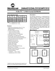
PIC24F Family Reference Manual<strong>29.</strong>1 INTRODUCTIONThis section discusses the <strong>Real</strong>-<strong>Time</strong> <strong>Clock</strong> <strong>and</strong> <strong>Calendar</strong> hardware module, available onPIC24F devices, <strong>and</strong> its operation. Listed below are some of the key features of this module:• <strong>Time</strong>: Hours, Minutes <strong>and</strong> Seconds• 24-Hour Format (Military <strong>Time</strong>)• <strong>Calendar</strong>: Weekday, Date, Month <strong>and</strong> Year• Alarm Configurable• Year Range: 2000 to 2099• Leap Year Correction• BCD Format for Compact Firmware• Optimized for Low-Power Operation• User Calibration with Auto-Adjust• Calibration Range: ±2.64 Seconds Error per Month• Requirements: External 32.768 kHz <strong>Clock</strong> Crystal• Alarm Pulse or Seconds <strong>Clock</strong> Output on <strong>RTCC</strong> pinThis module provides a <strong>Real</strong>-<strong>Time</strong> <strong>Clock</strong> <strong>and</strong> <strong>Calendar</strong> (<strong>RTCC</strong>) function. The module is intendedfor applications where accurate time must be maintained for extended periods of time with minimumto no intervention from the CPU. The module is optimized for low-power usage in order toprovide extended battery lifetime while keeping track of time.The <strong>RTCC</strong> module is a 100-year clock <strong>and</strong> calendar with automatic leap year detection. The rangeof the clock is from 00:00:00 (midnight) on January 1, 2000 to 23:59:59 on December 31, 2099.The hours are available in 24-hour (military time) format. The clock provides a granularity of onesecond with half-second visibility to the user.Figure 29-1:<strong>RTCC</strong> Block Diagram<strong>RTCC</strong> <strong>Clock</strong> DomainCPU <strong>Clock</strong> Domain32.768 kHz Inputfrom SOSC OscillatorAlarmEvent<strong>RTCC</strong> Prescalers0.5s<strong>RTCC</strong> <strong>Time</strong>rComparatorRCFGCALALCFGRPTRTCVALYEARMTHDAYWKDYHRMINSECCompare Registerswith MasksALRMVALALMTHDYALWDHRALMINSECRepeat Counter<strong>RTCC</strong> Interrupt Logic<strong>RTCC</strong> InterruptAlarm Pulse<strong>RTCC</strong> PinRTCOEDS39696A-page 29-2 Advance Information © 2006 <strong>Microchip</strong> Technology Inc.
<strong>Section</strong> <strong>29.</strong> <strong>Real</strong>-<strong>Time</strong> <strong>Clock</strong> <strong>and</strong> <strong>Calendar</strong> (<strong>RTCC</strong>)<strong>29.</strong>2 <strong>RTCC</strong> MODULE REGISTERSThis section discusses the <strong>RTCC</strong> module registers which are organized into the following threecategories:<strong>RTCC</strong> Control Registers• RCFGCAL• PADCFG1• ALCFGRPT<strong>RTCC</strong> Value Registers• RTCVAL (the following four registers are addressed through the RTCVAL register)- YEAR- MTHDY- WKDYHR- MINSECAlarm Value Registers• ALRMVAL (the following three registers are addressed through the ALRMVAL register)- ALMTHDY- ALWDHR- ALMINSECNote:For reference purposes, the upper half of the RTCVAL register will be referred to asRTCVAL <strong>and</strong> the lower half as RTCVAL. The same applies toALRMVAL, where the upper half is ALRMVALH <strong>and</strong> the lower half is ALRMVALL.29<strong>Real</strong>-<strong>Time</strong> <strong>Clock</strong>/<strong>Calendar</strong> (<strong>RTCC</strong>)© 2006 <strong>Microchip</strong> Technology Inc. Advance Information DS39696A-page 29-3
PIC24F Family Reference Manual<strong>29.</strong>2.1 <strong>RTCC</strong> Control RegistersRegister 29-1: RCFGCAL: <strong>RTCC</strong> Calibration <strong>and</strong> Configuration Register (1)R/W-0 U-0 R/W-0 R-0 R-0 R/W-0 R/W-0 R/W-0RTCEN (2) — RTCWREN RTCSYNC HALFSEC (3) RTCOE RTCPTR1 RTCPTR0bit 15 bit 8R/W-0 R/W-0 R/W-0 R/W-0 R/W-0 R/W-0 R/W-0 R/W-0CAL7 CAL6 CAL5 CAL4 CAL3 CAL2 CAL1 CAL0bit 7 bit 0Legend:R = Readable bit W = Writable bit U = Unimplemented bit, read as ‘0’-n = Value at POR ‘1’ = Bit is set ‘0’ = Bit is cleared x = Bit is unknownbit 15 RTCEN: <strong>RTCC</strong> Enable bit (2)1 = <strong>RTCC</strong> module is enabled0 = <strong>RTCC</strong> module is disabledbit 14 Unimplemented: Read as ‘0’bit 13RTCWREN: <strong>RTCC</strong> Value Registers Write Enable bit1 = RTCVAL <strong>and</strong> RTCVAL registers can be written to by the user0 = RTCVAL <strong>and</strong> RTCVAL registers are locked out from being written to by the userbit 12 RTCSYNC: <strong>RTCC</strong> Value Registers Read Synchronization bit1 = RTCVAL, RTCVAL <strong>and</strong> ALCFGRPT registers can change while reading due to arollover ripple resulting in an invalid data read. If the register is read twice <strong>and</strong> results in the samedata, the data can be assumed to be valid.0 = RTCVAL, RTCVAL or ALCFGRPT registers can be read without concern over arollover ripplebit 11 HALFSEC: Half-Second Status bit (3)bit 10bit 9-81 = Second half period of a second0 = First half period of a secondRTCOE: <strong>RTCC</strong> Output Enable bit1 = <strong>RTCC</strong> clock output enabled0 = <strong>RTCC</strong> clock output disabledRTCPTR: <strong>RTCC</strong> Value Register Window Pointer bitsPoints to the corresponding <strong>RTCC</strong> Value registers when reading RTCVAL <strong>and</strong> RTCVALregisters; the RTCPTR value decrements on every read or write of RTCVAL until itreaches ‘00’.RTCVAL:00 = MINUTES01 = WEEKDAY10 = MONTH11 = ReservedRTCVAL:00 = SECONDS01 = HOURS10 = DAY11 = YEARNote 1: The RCFGCAL register is only affected by a POR.2: A write to the RTCEN bit is only allowed when RTCWREN = 1.3: This bit is read-only. It is cleared to ‘0’ on a write to the lower half of the MINSEC register.DS39696A-page 29-4 Advance Information © 2006 <strong>Microchip</strong> Technology Inc.
PIC24F Family Reference ManualRegister 29-3:ALCFGRPT: Alarm Configuration RegisterR/W-0 R/W-0 R/W-0 R/W-0 R/W-0 R/W-0 R/W-0 R/W-0ALRMEN CHIME AMASK3 AMASK2 AMASK1 AMASK0 ALRMPTR1 ALRMPTR0bit 15 bit 8R/W-0 R/W-0 R/W-0 R/W-0 R/W-0 R/W-0 R/W-0 R/W-0ARPT7 ARPT6 ARPT5 ARPT4 ARPT3 ARPT2 ARPT1 ARPT0bit 7 bit 0Legend:R = Readable bit W = Writable bit U = Unimplemented bit, read as ‘0’-n = Value at POR ‘1’ = Bit is set ‘0’ = Bit is cleared x = Bit is unknownbit 15bit 14bit 13-10bit 9-8bit 7-0ALRMEN: Alarm Enable bit1 = Alarm is enabled (cleared automatically after an alarm event whenever ARPT = 00 <strong>and</strong>CHIME = 0)0 = Alarm is disabledCHIME: Chime Enable bit1 = Chime is enabled; ARPT is allowed to roll over from 00h to FFh0 = Chime is disabled; ARPT stops once it reaches 00hAMASK: Alarm Mask Configuration bits0000 = Every half second0001 = Every second0010 = Every 10 seconds0011 = Every minute0100 = Every 10 minutes0101 = Every hour0110 = Once a day0111 = Once a week1000 = Once a month1001 = Once a year (except when configured for February 29th, once every 4 years)101x = Reserved – do not use11xx = Reserved – do not useALRMPTR: Alarm Value Register Window Pointer bitsPoints to the corresponding Alarm Value registers when reading ALRMVALH <strong>and</strong> ALRMVALL registers;the ALRMPTR value decrements on every read or write of ALRMVALH until it reaches ‘00’.ALRMVAL:00 = ALRMMIN01 = ALRMWD10 = ALRMMNTH11 = UnimplementedALRMVAL:00 = ALRMSEC01 = ALRMHR10 = ALRMDAY11 = UnimplementedARPT: Alarm Repeat Counter Value bits11111111 = Alarm will repeat 255 more times...00000000 = Alarm will not repeatThe counter decrements on any alarm event. The counter is prevented from rolling over from 00h toFFh unless CHIME = 1.DS39696A-page 29-6 Advance Information © 2006 <strong>Microchip</strong> Technology Inc.
<strong>Section</strong> <strong>29.</strong> <strong>Real</strong>-<strong>Time</strong> <strong>Clock</strong> <strong>and</strong> <strong>Calendar</strong> (<strong>RTCC</strong>)<strong>29.</strong>2.2 RTCVAL Register MappingsRegister 29-4: YEAR: Year Value Register (1)U-0 U-0 U-0 U-0 U-0 U-0 U-0 U-0— — — — — — — —bit 15 bit 8R/W-x R/W-x R/W-x R/W-x R/W-x R/W-x R/W-x R/W-xYRTEN3 YRTEN2 YRTEN1 YRTEN0 YRONE3 YRONE2 YRONE1 YRONE0bit 7 bit 0Legend:R = Readable bit W = Writable bit U = Unimplemented bit, read as ‘0’-n = Value at POR ‘1’ = Bit is set ‘0’ = Bit is cleared x = Bit is unknownbit 15-8 Unimplemented: Read as ‘0’bit 7-4 YRTEN: Binary Coded Decimal Value of Year’s Tens Digit; Contains a value from 0 to 9bit 3-0 YRONE: Binary Coded Decimal Value of Year’s Ones Digit; Contains a value from 0 to 9Note 1: A write to the YEAR register is only allowed when RTCWREN = 1.Register 29-5: MTHDY: Month <strong>and</strong> Day Value Register (1)U-0 U-0 U-0 R/W-x R/W-x R/W-x R/W-x R/W-x— — — MTHTEN0 MTHONE3 MTHONE2 MTHONE1 MTHONE0bit 15 bit 8U-0 U-0 R/W-x R/W-x R/W-x R/W-x R/W-x R/W-x— — DAYTEN1 DAYTEN0 DAYONE3 DAYONE2 DAYONE1 DAYONE0bit 7 bit 029Legend:R = Readable bit W = Writable bit U = Unimplemented bit, read as ‘0’-n = Value at POR ‘1’ = Bit is set ‘0’ = Bit is cleared x = Bit is unknownbit 15-13 Unimplemented: Read as ‘0’bit 12 MTHTEN0: Binary Coded Decimal Value of Month’s Tens Digit; Contains a value of 0 or 1bit 11-8 MTHONE: Binary Coded Decimal Value of Month’s Ones Digit; Contains a value from 0 to 9bit 7-6 Unimplemented: Read as ‘0’bit 5-4 DAYTEN: Binary Coded Decimal value of Day’s Tens Digit; Contains a value from 0 to 3bit 3-0 DAYONE: Binary Coded Decimal Value of Day’s Ones Digit; Contains a value from 0 to 9<strong>Real</strong>-<strong>Time</strong> <strong>Clock</strong>/<strong>Calendar</strong> (<strong>RTCC</strong>)Note 1: A write to this register is only allowed when RTCWREN = 1.© 2006 <strong>Microchip</strong> Technology Inc. Advance Information DS39696A-page 29-7
PIC24F Family Reference ManualRegister 29-6: WKDYHR: Weekday <strong>and</strong> Hours Value Register (1)U-0 U-0 U-0 U-0 U-0 R/W-x R/W-x R/W-x— — — — — WDAY2 WDAY1 WDAY0bit 15 bit 8U-0 U-0 R/W-x R/W-x R/W-x R/W-x R/W-x R/W-x— — HRTEN1 HRTEN0 HRONE3 HRONE2 HRONE1 HRONE0bit 7 bit 0Legend:R = Readable bit W = Writable bit U = Unimplemented bit, read as ‘0’-n = Value at POR ‘1’ = Bit is set ‘0’ = Bit is cleared x = Bit is unknownbit 15-11 Unimplemented: Read as ‘0’bit 10-8 WDAY: Binary Coded Decimal Value of Weekday Digit; Contains a value from 0 to 6bit 7-6 Unimplemented: Read as ‘0’bit 5-4 HRTEN: Binary Coded Decimal Value of Hour’s Tens Digit; Contains a value from 0 to 2bit 3-0 HRONE: Binary Coded Decimal Value of Hour’s Ones Digit; Contains a value from 0 to 9Note 1: A write to this register is only allowed when RTCWREN = 1.Register 29-7:MINSEC: Minutes <strong>and</strong> Seconds Value RegisterU-0 R/W-x R/W-x R/W-x R/W-x R/W-x R/W-x R/W-x— MINTEN2 MINTEN1 MINTEN0 MINONE3 MINONE2 MINONE1 MINONE0bit 15 bit 8U-0 R/W-x R/W-x R/W-x R/W-x R/W-x R/W-x R/W-x— SECTEN2 SECTEN1 SECTEN0 SECONE3 SECONE2 SECONE1 SECONE0bit 7 bit 0Legend:R = Readable bit W = Writable bit U = Unimplemented bit, read as ‘0’-n = Value at POR ‘1’ = Bit is set ‘0’ = Bit is cleared x = Bit is unknownbit 15 Unimplemented: Read as ‘0’bit 14-12 MINTEN: Binary Coded Decimal Value of Minute’s Tens Digit; Contains a value from 0 to 5bit 11-8 MINONE: Binary Coded Decimal Value of Minute’s Ones Digit; Contains a value from 0 to 9bit 7 Unimplemented: Read as ‘0’bit 6-4 SECTEN: Binary Coded Decimal Value of Second’s Tens Digit; Contains a value from 0 to 5bit 3-0 SECONE: Binary Coded Decimal Value of Second’s Ones Digit; Contains a value from 0 to 9DS39696A-page 29-8 Advance Information © 2006 <strong>Microchip</strong> Technology Inc.
<strong>Section</strong> <strong>29.</strong> <strong>Real</strong>-<strong>Time</strong> <strong>Clock</strong> <strong>and</strong> <strong>Calendar</strong> (<strong>RTCC</strong>)<strong>29.</strong>2.3 ALRMVAL Register MappingsRegister 29-8: ALMTHDY: Alarm Month <strong>and</strong> Day Value Register (1)U-0 U-0 U-0 R/W-x R/W-x R/W-x R/W-x R/W-x— — — MTHTEN0 MTHONE3 MTHONE2 MTHONE1 MTHONE0bit 15 bit 8U-0 U-0 R/W-x R/W-x R/W-x R/W-x R/W-x R/W-x— — DAYTEN1 DAYTEN0 DAYONE3 DAYONE2 DAYONE1 DAYONE0bit 7 bit 0Legend:R = Readable bit W = Writable bit U = Unimplemented bit, read as ‘0’-n = Value at POR ‘1’ = Bit is set ‘0’ = Bit is cleared x = Bit is unknownbit 15-13 Unimplemented: Read as ‘0’bit 12 MTHTEN0: Binary Coded Decimal Value of Month’s Tens Digit; Contains a value of 0 or 1bit 11-8 MTHONE: Binary Coded Decimal Value of Month’s Ones Digit; Contains a value from 0 to 9bit 7-6 Unimplemented: Read as ‘0’bit 5-4 DAYTEN: Binary Coded Decimal Value of Day’s Tens Digit; Contains a value from 0 to 3bit 3-0 DAYONE: Binary Coded Decimal Value of Day’s Ones Digit; Contains a value from 0 to 9Note 1: A write to this register is only allowed when RTCWREN = 1.Register 29-9: ALWDHR: Alarm Weekday <strong>and</strong> Hours Value Register (1)U-0 U-0 U-0 U-0 U-0 R/W-x R/W-x R/W-x— — — — — WDAY2 WDAY1 WDAY0bit 15 bit 8U-0 U-0 R/W-x R/W-x R/W-x R/W-x R/W-x R/W-x— — HRTEN1 HRTEN0 HRONE3 HRONE2 HRONE1 HRONE0bit 7 bit 0Legend:R = Readable bit W = Writable bit U = Unimplemented bit, read as ‘0’-n = Value at POR ‘1’ = Bit is set ‘0’ = Bit is cleared x = Bit is unknownbit 15-11 Unimplemented: Read as ‘0’bit 10-8 WDAY: Binary Coded Decimal Value of Weekday Digit; Contains a value from 0 to 6bit 7-6 Unimplemented: Read as ‘0’bit 5-4 HRTEN: Binary Coded Decimal Value of Hour’s Tens Digit; Contains a value from 0 to 2bit 3-0 HRONE: Binary Coded Decimal Value of Hour’s Ones Digit; Contains a value from 0 to 929<strong>Real</strong>-<strong>Time</strong> <strong>Clock</strong>/<strong>Calendar</strong> (<strong>RTCC</strong>)Note 1: A write to this register is only allowed when RTCWREN = 1.© 2006 <strong>Microchip</strong> Technology Inc. Advance Information DS39696A-page 29-9
PIC24F Family Reference ManualRegister 29-10:ALMINSEC: Alarm Minutes <strong>and</strong> Seconds Value RegisterU-0 R/W-x R/W-x R/W-x R/W-x R/W-x R/W-x R/W-x— MINTEN2 MINTEN1 MINTEN0 MINONE3 MINONE2 MINONE1 MINONE0bit 15 bit 8U-0 R/W-x R/W-x R/W-x R/W-x R/W-x R/W-x R/W-x— SECTEN2 SECTEN1 SECTEN0 SECONE3 SECONE2 SECONE1 SECONE0bit 7 bit 0Legend:R = Readable bit W = Writable bit U = Unimplemented bit, read as ‘0’-n = Value at POR ‘1’ = Bit is set ‘0’ = Bit is cleared x = Bit is unknownbit 15 Unimplemented: Read as ‘0’bit 14-12 MINTEN: Binary Coded Decimal Value of Minute’s Tens Digit; Contains a value from 0 to 5bit 11-8 MINONE: Binary Coded Decimal Value of Minute’s Ones Digit; Contains a value from 0 to 9bit 7 Unimplemented: Read as ‘0’bit 6-4 SECTEN: Binary Coded Decimal Value of Second’s Tens Digit; Contains a value from 0 to 5bit 3-0 SECONE: Binary Coded Decimal Value of Second’s Ones Digit; Contains a value from 0 to 9<strong>29.</strong>2.4 RTCEN Bit WriteAn attempt to write to the RTCEN bit while RTCWREN = 0 will be ignored. RTCWREN must beset <strong>and</strong> then a write to RTCEN will take place.Like the RTCEN bit, the RTCVAL <strong>and</strong> RTCVAL registers can only be written to whenRTCWREN = 1. A write to these registers while RTCWREN = 0 will be ignored as well.DS39696A-page 29-10 Advance Information © 2006 <strong>Microchip</strong> Technology Inc.
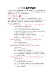
<strong>Section</strong> <strong>29.</strong> <strong>Real</strong>-<strong>Time</strong> <strong>Clock</strong> <strong>and</strong> <strong>Calendar</strong> (<strong>RTCC</strong>)<strong>29.</strong>3 OPERATION<strong>29.</strong>3.1 Register InterfaceThe register interface for the <strong>RTCC</strong> <strong>and</strong> alarm values is implemented using the Binary CodedDecimal (BCD) format. This simplifies the firmware, when using the module, as each of the digitvalues is contained within its own 4-bit value (see Figure 29-2).Figure 29-2:<strong>Time</strong>r <strong>and</strong> Alarm Digit FormatTIME BCDYEARMONTHDAYDAY OF WEEK0-9 0-9 0-1 0-9 0-3 0-90-6HOURS(24-hr format) MINUTES SECONDS1/2 SECOND BIT(binary format)0-2 0-9 0-5 0-9 0-5 0-90/1ALARM BCDMONTHDAYDAY OF WEEK0-1 0-90-3 0-9HOURS(24-hr format) MINUTES SECONDS0-2 0-9 0-5 0-9 0-5 0-90-629<strong>Real</strong>-<strong>Time</strong> <strong>Clock</strong>/<strong>Calendar</strong> (<strong>RTCC</strong>)© 2006 <strong>Microchip</strong> Technology Inc. Advance Information DS39696A-page 29-11
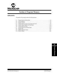
PIC24F Family Reference Manual<strong>29.</strong>3.2 <strong>Clock</strong> SourceAs mentioned earlier, the <strong>RTCC</strong> module is intended to be clocked by an external <strong>Real</strong>-<strong>Time</strong><strong>Clock</strong> crystal oscillating at 32.768 kHz. Calibration of the crystal can be accomplished throughthis module yielding an error of 3 seconds or less per month (see <strong>Section</strong> <strong>29.</strong>3.9 “Calibration”for further details).Figure 29-3:<strong>Clock</strong> Source Multiplexing32.768 kHz XTAL 1:16384from SOSC <strong>Clock</strong> Prescaler (1)1/2 sec<strong>Clock</strong>1/2 sec (1)1 sec <strong>Clock</strong>sechr:minDayDay of WeekMonthYearNote 1:Writing to the lower half of the MINSEC register resets all counters, allowing fraction of a secondsynchronization; clock prescaler is held in Reset when RTCEN = 0.<strong>29.</strong>3.2.1 REAL-TIME CLOCK CRYSTAL ENABLETo allow the <strong>RTCC</strong> module to be clocked by an external 32.768 kHz crystal, the SOSCEN bit inthe OSCCON register (see <strong>Section</strong> 6. “Oscillator”, Register 6-1) must be set. This is the onlybit outside of the <strong>RTCC</strong> module that the user must be concerned with for enabling the <strong>RTCC</strong>.DS39696A-page 29-12 Advance Information © 2006 <strong>Microchip</strong> Technology Inc.
<strong>Section</strong> <strong>29.</strong> <strong>Real</strong>-<strong>Time</strong> <strong>Clock</strong> <strong>and</strong> <strong>Calendar</strong> (<strong>RTCC</strong>)<strong>29.</strong>3.3 Digit Carry RulesThis section explains which timer values are affected when there is a rollover.• <strong>Time</strong> of Day: from 23:59:59 to 00:00:00 with a carry to the day field• Month: from 12/31 to 01/01 with a carry to the year field• Day of Week: from 6 to 0 with no carry (refer to Table 29-1)• Year Carry: from 99 to 00; this also surpasses the use of the <strong>RTCC</strong>Refer to Table 29-2 for the day to month rollover schedule.Considering that the following values are in BCD format, the carry to the upper BCD digit will occur ata count of 10 <strong>and</strong> not a count of 16 (SECONDS, MINUTES, HOURS, WEEKDAY, DAYS, MONTHS).Table 29-1:Day of Week ScheduleDay of WeekSunday 0Monday 1Tuesday 2Wednesday 3Thursday 4Friday 5Saturday 6Table 29-2:<strong>29.</strong>3.4 Leap YearDay to Month Rollover ScheduleMonthMaximum Day Field01 (January) 3102 (February) 28 or 29 (see <strong>Section</strong> <strong>29.</strong>3.4 “Leap Year”)03 (March) 3104 (April) 3005 (May) 3106 (June) 3007 (July) 3108 (August) 3109 (September) 3010 (October) 3111 (November) 3012 (December) 31Since the year range on the <strong>RTCC</strong> module is 2000 to 2099, the leap calculation is determined byany year divisible by 4 in the above range. The only month to be affected in a leap year is February.The month of February will have 29 days in a leap year, while any other year will have 28 days.29<strong>Real</strong>-<strong>Time</strong> <strong>Clock</strong>/<strong>Calendar</strong> (<strong>RTCC</strong>)© 2006 <strong>Microchip</strong> Technology Inc. Advance Information DS39696A-page 29-13
PIC24F Family Reference Manual<strong>29.</strong>3.5 General FunctionalityAll <strong>Time</strong>r registers containing a time value of seconds or greater are writable. The user canconfigure the time by simply writing to these registers the desired year, month, day, hour, minutes<strong>and</strong> seconds via register pointers (see <strong>Section</strong> <strong>29.</strong>3.8 “Register Mapping”). The timer will thenuse the newly written values <strong>and</strong> proceed with the count from the desired starting point. The <strong>RTCC</strong>module is enabled by setting the RTCEN bit (RCFGCAL). If enabled while adjusting these registers,the timer will still continue to increment. However, any time the MINSEC register is writtento, both of the timer prescalers are reset to ‘0’. This allows fraction of a second synchronization.The <strong>Time</strong>r registers are updated in the same cycle as the write instruction is executed by theCPU. The user is responsible to assure that when RTCEN = 1, the updated registers will not beincremented at the same time. This can be accomplished in several ways:• Checking the RTCSYNC bit (RCFGCAL)• Checking the preceding digits from which a carry can occur• Updating the registers immediately following the seconds pulse (or alarm interrupt)The user has visibility to the half-second field of the counter. This value is read-only <strong>and</strong> can onlybe reset by writing to the lower half of the MINSEC register.Note:Although the above precautions should be taken when updating the registers, forsome of the registers, large windows of time are available for updating. For example,the upper byte of the MTHDY register is only clocked once a month, whereasthe lower byte is clocked once a day.<strong>29.</strong>3.6 Safety Window for Register Reads <strong>and</strong> WritesThe RTCSYNC bit indicates a time window during which the <strong>RTCC</strong> clock domain registers canbe safely read <strong>and</strong> written without concern about a rollover. When RTCSYNC = 0, the registerscan be safely accessed by the CPU. Whether RTCSYNC = 1 or 0, the user should employ afirmware solution to assure that the data read did not fall on a rollover boundary, resulting in aninvalid or partial read. This firmware solution would consist of reading each register twice <strong>and</strong>then comparing the two values. If the two values match, then a rollover did not occur.<strong>29.</strong>3.7 Write LockIn order to perform a write to any of the <strong>RTCC</strong> <strong>Time</strong>r registers, the RTCWREN bit(RCFGCAL) must be set (refer to Example 29-1).Example 29-1: Setting the RTCWREN BitMOV #NVMKEY, W1 ;move the address of NVMKEY into W1MOV.b #0x55, W2MOV.b #0xAA, W3MOV.b W2, [W1] ;start 55/AA sequenceMOV.b W3, [W1]BSET RCFGCAL, #13 ;set the RTCWREN bitNote:To avoid accidental writes to the timer, it is recommended that the RTCWREN bit(RCFGCAL) is kept clear at any other time. For the RTCWREN bit to be set,there is only 1 instruction cycle time window allowed between the 55h/AA sequence<strong>and</strong> the setting of RTCWREN; therefore, it is recommended that the code examplein Example 29-1 be followed.DS39696A-page 29-14 Advance Information © 2006 <strong>Microchip</strong> Technology Inc.
<strong>Section</strong> <strong>29.</strong> <strong>Real</strong>-<strong>Time</strong> <strong>Clock</strong> <strong>and</strong> <strong>Calendar</strong> (<strong>RTCC</strong>)<strong>29.</strong>3.8 Register MappingTo limit the register interface, the <strong>RTCC</strong> <strong>Time</strong>r <strong>and</strong> Alarm <strong>Time</strong> registers are accessed throughcorresponding register pointers. The <strong>RTCC</strong> Value register window (RTCVAL <strong>and</strong>RTCVAL) uses the RTCPTR bits (RCFGCAL) to select the desired <strong>Time</strong>r register pair(see Table 29-3).By reading or writing the RTCVAL register, the <strong>RTCC</strong> pointer value, RTCPTR, decrementsby one until it reaches ‘00’. Once it reaches ‘00’, the MINUTES <strong>and</strong> SECONDS valuewill be accessible through RTCVAL <strong>and</strong> RTCVAL until the pointer value is manuallychanged.Table 29-3:RTCPTRRTCVAL Register Mapping<strong>RTCC</strong> Value Register WindowRTCVALRTCVAL00 MINUTES SECONDS01 WEEKDAY HOURS10 MONTH DAY11 — YEARThe Alarm Value register window (ALRMVALH <strong>and</strong> ALRMVALL) uses the ALRMPTR bits(ALCFGRPT) to select the desired Alarm register pair (see Table 29-4).By reading or writing the ALRMVALH register, the alarm pointer value, ALRMPTR,decrements by one until it reaches ‘00’. Once it reaches ‘00’, the ALRMMIN AND ALRMSEC valuewill be accessible through ALRMVALH <strong>and</strong> ALRMVALL until the pointer value is manually changed.Table 29-4:ALRMPTRALRMVAL Register MappingAlarm Value Register WindowALRMVALALRMVAL00 ALRMMIN ALRMSEC01 ALRMWD ALRMHR10 ALRMMNTH ALRMDAY11 — —Considering that the 16-bit core does not distinguish between 8-bit <strong>and</strong> 16-bit read operations,the user must be aware that when reading either the ALRMVALH or ALRMVALL register, it willdecrement the ALRMPTR value. The same applies to the RTCVAL orRTCVAL register with the RTCPTR being decremented.Note:This only applies to read operations <strong>and</strong> not write operations. Write operations canbe byte specific.29<strong>Real</strong>-<strong>Time</strong> <strong>Clock</strong>/<strong>Calendar</strong> (<strong>RTCC</strong>)© 2006 <strong>Microchip</strong> Technology Inc. Advance Information DS39696A-page 29-15
PIC24F Family Reference Manual<strong>29.</strong>3.9 CalibrationThe real-time crystal input can be calibrated using the periodic auto-adjust feature. Whenproperly calibrated, the <strong>RTCC</strong> can provide an error of less than 3 seconds per month. This isaccomplished by finding the number of error clock pulses <strong>and</strong> storing the value into the lower halfof the RCFGCAL register. The 8-bit signed value loaded into the lower half of RCFGCAL ismultiplied by four <strong>and</strong> will be either added or subtracted from the <strong>RTCC</strong> timer once every minute.Refer to the steps below for <strong>RTCC</strong> calibration:1. Using another timer resource on the device, the user must find the error of the 32.768 kHzcrystal.2. Once the error is known, it must be converted to the number of error clock pulses perminute. Formula box:(Ideal Frequency (32,758) – Measured Frequency) * 60 = Error <strong>Clock</strong>s per Minute3. a) If the oscillator is faster than ideal (negative result from step 2), the RCFGCAL registervalue needs to be negative. This causes the specified number of clock pulses to besubtracted from the timer counter once every minute.b) If the oscillator is slower than ideal (positive result from step 2), the RCFGCAL registervalue needs to be positive. This causes the specified number of clock pulses to be added tothe timer counter once every minute.4. Load the RCFGCAL register with the correct value.Writes to the lower half of the RCFGCAL register should only occur when the timer is turned off,or immediately after the rising edge of the seconds pulse.Note:It is up to the user to include in the error value the initial error of the crystal, drift dueto temperature <strong>and</strong> drift due to crystal aging.DS39696A-page 29-16 Advance Information © 2006 <strong>Microchip</strong> Technology Inc.
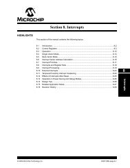
<strong>Section</strong> <strong>29.</strong> <strong>Real</strong>-<strong>Time</strong> <strong>Clock</strong> <strong>and</strong> <strong>Calendar</strong> (<strong>RTCC</strong>)<strong>29.</strong>4 ALARM• Configurable from half second to one year• Enabled using the ALRMEN bit (ALCFGRPT, Register 29-3)• One-time alarm <strong>and</strong> repeat alarm options available<strong>29.</strong>4.1 Configuring the AlarmThe alarm feature is enabled using the ALRMEN bit. This bit is cleared when an alarm is issued.This bit will not be cleared if the CHIME bit = 1, or if the lower half of ALCFGRPT ≠ 00.The interval selection of the alarm is configured through the AMASK bits (ALCFGRPT),see Figure 29-4. These bits determine which <strong>and</strong> how many digits of the alarm must match theclock value for the alarm to occur. The alarm can also be configured to repeat based on a preconfiguredinterval. The amount of times this occurs once the alarm is enabled is stored in thelower half of the ALCFGRPT register.Note: Changing any of the registers, other then the RCFGCAL <strong>and</strong> ALCFGRPT registers<strong>and</strong> the CHIME bit while the alarm is enabled (ALRMEN = 1), can result in a falsealarm event leading to a false alarm interrupt. To avoid a false alarm event, the timer<strong>and</strong> alarm values should only be changed while the alarm is disabled(ALRMEN = 0). It is recommended that the ALCFGRPT register <strong>and</strong> CHIME bit bechanged when RTCSYNC = 0.Figure 29-4:Alarm Mask SettingsAlarm Mask SettingAMASKDay of theWeek Month Day Hours Minutes Seconds0000 – Every half second0001 – Every second0010 – Every 10 secondss0011 – Every minutess0100 – Every 10 minutes0101 – Every hourm s sm m s s290110 – Every day0111 – Every week1000 – Every month1001 – Every year (1)h h m m s sd h h m m s sd d h h m m s sm m d d h h m m s s<strong>Real</strong>-<strong>Time</strong> <strong>Clock</strong>/<strong>Calendar</strong> (<strong>RTCC</strong>)Note 1: Annually, except when configured for February <strong>29.</strong>© 2006 <strong>Microchip</strong> Technology Inc. Advance Information DS39696A-page 29-17
PIC24F Family Reference ManualWhen ALCFGRPT = 00 <strong>and</strong> CHIME bit = 0 (ALCFGRPT), the repeat function is disabled<strong>and</strong> only a single alarm will occur. The alarm can be repeated up to 255 times by loading thelower half of the ALCFGRPT register with FFh.After each alarm is issued, the ALCFGRPT register is decremented by one. Once the registerhas reached ‘00’, the alarm will be issued one last time, after which the ALRMEN bit will becleared automatically <strong>and</strong> the alarm will turn off. Indefinite repetition of the alarm can occur if theCHIME bit = 1. Instead of the alarm being disabled when the ALCFGRPT register reaches ‘00’,it will roll over to FF <strong>and</strong> continue counting indefinitely when CHIME = 1.<strong>29.</strong>4.2 Alarm InterruptAt every alarm event, an interrupt is generated. In addition, an alarm pulse output is provided thatoperates at half the frequency of the alarm. This output is completely synchronous to the <strong>RTCC</strong>clock <strong>and</strong> can be used as a trigger clock to other peripherals. This output is available on the<strong>RTCC</strong> pin. The output pulse is a clock with a 50% duty cycle <strong>and</strong> a frequency half that of thealarm event (see Figure 29-5).The <strong>RTCC</strong> pin is also capable of outputting the seconds clock. The user can select between thealarm pulse, generated by the <strong>RTCC</strong> module, or the seconds clock output. The RTSECSEL(PADCFG1) bit selects between these two outputs. When RTSECSEL = 0, the alarm pulseis selected. When RTSECSEL = 1, the seconds clock is selected.Figure 29-5:<strong>Time</strong>r Pulse GenerationRTCEN bitALRMEN bit<strong>RTCC</strong> Alarm Event<strong>RTCC</strong> PinDS39696A-page 29-18 Advance Information © 2006 <strong>Microchip</strong> Technology Inc.
<strong>Section</strong> <strong>29.</strong> <strong>Real</strong>-<strong>Time</strong> <strong>Clock</strong> <strong>and</strong> <strong>Calendar</strong> (<strong>RTCC</strong>)<strong>29.</strong>5 SLEEP MODE<strong>29.</strong>6 RESETThe timer <strong>and</strong> alarm continue to operate while in Sleep mode. The operation of the alarm is notaffected by Sleep, as an alarm event can always wake-up the CPU.Idle mode does not affect the operation of the timer or alarm.<strong>29.</strong>6.1 Device ResetWhen a device Reset occurs, the ALCFGRPT register is forced to its Reset state, causing thealarm to be disabled (if enabled prior to the Reset). If the <strong>RTCC</strong> was enabled, it will continue tooperate when a basic device Reset occurs.<strong>29.</strong>6.2 Power-on Reset (POR)The RCFGCAL <strong>and</strong> ALCFGRPT registers are only reset on a POR. Once the device exits thePOR state, the clock registers should be reloaded with the desired values.The timer prescaler values can only be reset by writing to the Seconds register. No device Resetcan affect the prescalers.<strong>29.</strong>7 PERIPHERAL MODULE DISABLE (PMD) REGISTERThe Peripheral Module Disable (PMD) registers provide a method to disable the <strong>RTCC</strong> moduleby stopping all clock sources supplied to that module. When a peripheral is disabled via theappropriate PMD control bit, the peripheral is in a minimum power consumption state. The control<strong>and</strong> status registers associated with the peripheral will also be disabled, so writes to those registerswill have no effect <strong>and</strong> read values will be invalid. A peripheral module will only be enabledif the <strong>RTCC</strong>MD bit in the the PMDx register is cleared.29<strong>Real</strong>-<strong>Time</strong> <strong>Clock</strong>/<strong>Calendar</strong> (<strong>RTCC</strong>)© 2006 <strong>Microchip</strong> Technology Inc. Advance Information DS39696A-page 29-19
PIC24F Family Reference Manual<strong>29.</strong>8 REGISTER MAPSA summary of the registers associated with the PIC24F <strong>RTCC</strong> module is provided in Table 29-5 <strong>and</strong> Table 29-6.Table 29-5: Pad Configuration MapFile Name Bit 15 Bit 14 Bit 13 Bit 12 Bit 11 Bit 10 Bit 9 Bit 8 Bit 7 Bit 6 Bit 5 Bit 4 Bit 3 Bit 2 Bit 1 Bit 0AllResetsPADCFG1 — — — — — — — — — — — — — — RTSECSEL PMPTTL 0000Legend: — = unimplemented, read as ‘0’. Reset values are shown in hexadecimal for 100-pin devices.Table 29-6: <strong>Real</strong>-<strong>Time</strong> <strong>Clock</strong> <strong>and</strong> <strong>Calendar</strong> Register MapFile Name Bit 15 Bit 14 Bit 13 Bit 12 Bit 11 Bit 10 Bit 9 Bit 8 Bit 7 Bit 6 Bit 5 Bit 4 Bit 3 Bit 2 Bit 1 Bit 0AllResetsALRMVAL Alarm Value Register Window based on APTR xxxxALCFGRPT ALRMEN CHIME AMASK3 AMASK2 AMASK1 AMASK0 ALRMPTR1 ALRMPTR0 ARPT7 ARPT6 ARPT5 ARPT4 ARPT3 ARPT2 ARPT1 ARPT0 0000RTCVAL <strong>RTCC</strong> Value Register Window based on RTCPTR xxxxRCFGCAL (1) RTCEN — RTCWREN RTCSYNC HALFSEC RTCOE RTCPTR1 RTCPTR0 CAL7 CAL6 CAL5 CAL4 CAL3 CAL2 CAL1 CAL0 0000Legend: x = unknown value on Reset, — = unimplemented, read as ‘0’. Reset values are shown in hexadecimal.Note 1: RCFGCAL register Reset value dependent on type of Reset.DS39696A-page 29-20© 2006 <strong>Microchip</strong> Technology Inc.
<strong>Section</strong> <strong>29.</strong> <strong>Real</strong>-<strong>Time</strong> <strong>Clock</strong> <strong>and</strong> <strong>Calendar</strong> (<strong>RTCC</strong>)<strong>29.</strong>9 RELATED APPLICATION NOTESThis section lists application notes that are related to this section of the manual. Theseapplication notes may not be written specifically for the PIC24F device family, but the conceptsare pertinent <strong>and</strong> could be used with modification <strong>and</strong> possible limitations. The currentapplication notes related to the <strong>Real</strong>-<strong>Time</strong> <strong>Clock</strong> <strong>and</strong> <strong>Calendar</strong> (<strong>RTCC</strong>) module are:Title Application Note #No related application notes at this time.Note:Please visit the <strong>Microchip</strong> web site (www.microchip.com) for additional applicationnotes <strong>and</strong> code examples for the PIC24F family of devices.29<strong>Real</strong>-<strong>Time</strong> <strong>Clock</strong>/<strong>Calendar</strong> (<strong>RTCC</strong>)© 2006 <strong>Microchip</strong> Technology Inc. Advance Information DS39696A-page 29-21
PIC24F Family Reference Manual<strong>29.</strong>10 REVISION HISTORYRevision A (April 2006)This is the initial released revision of this document.DS39696A-page 29-22 Advance Information © 2006 <strong>Microchip</strong> Technology Inc.