MACHINING OPERATIONS AND MACHINE TOOLS Machining ...
MACHINING OPERATIONS AND MACHINE TOOLS Machining ...
MACHINING OPERATIONS AND MACHINE TOOLS Machining ...

You also want an ePaper? Increase the reach of your titles
YUMPU automatically turns print PDFs into web optimized ePapers that Google loves.
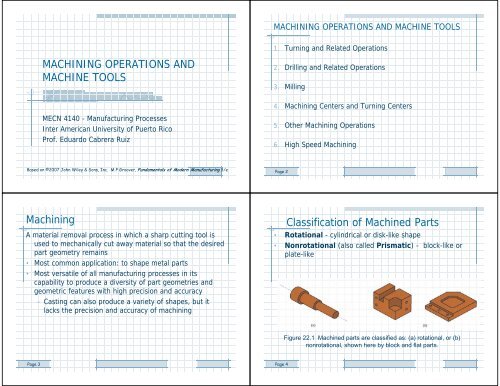
<strong>MACHINING</strong> <strong>OPERATIONS</strong> <strong>AND</strong> <strong>MACHINE</strong> <strong>TOOLS</strong>1. Turning and Related Operations<strong>MACHINING</strong> <strong>OPERATIONS</strong> <strong>AND</strong><strong>MACHINE</strong> <strong>TOOLS</strong>2. Drilling and Related Operations3. Milling4. <strong>Machining</strong> Centers and Turning CentersMECN 4140 - Manufacturing ProcessesInter American University of Puerto RicoProf. Eduardo Cabrera Ruiz5. Other <strong>Machining</strong> Operations6. High Speed <strong>Machining</strong>Based on ©2007 John Wiley & Sons, Inc. M P Groover, Fundamentals of Modern Manufacturing 3/ePage 2<strong>Machining</strong>A material removal process in which a sharp cutting tool isused to mechanically cut away material so that the desiredpart geometry remains• Most common application: to shape metal parts• Most versatile of all manufacturing processes in itscapability to produce a diversity of part geometries andgeometric features with high precision and accuracy– Casting can also produce a variety of shapes, but itlacks the precision and accuracy of machiningClassification of Machined Parts• Rotational - cylindrical or disk-like shape• Nonrotational (also called Prismatic) - block-like orplate-likeFigure 22.1 Machined parts are classified as: (a) rotational, or (b)nonrotational, shown here by block and flat parts.Page 3Page 4
<strong>Machining</strong> Operations and Part GeometryGenerating ShapeEach machining operation produces a characteristic partgeometry due to two factors:1. Relative motions between tool and workpart• Generating – part geometry determined by feedtrajectory of cutting tool2. Shape of the cutting tool• Forming – part geometry is created by the shape ofthe cutting toolPage 5Figure 22.2 Generating shape: (a) straight turning, (b) taper turning, (c) contourturning, (d) plain milling, (e) profile milling.Page 6Forming to Create ShapeForming and GeneratingFigure 22.3 Forming to create shape: (a) form turning, (b) drilling, and (c) broaching.Page 7Figure 22.4 Combination of forming and generating to create shape: (a) thread cutting ona lathe, and (b) slot milling.Page 8
TurningTurningSingle point cutting tool removes material from a rotatingworkpiece to generate a cylinder• Performed on a machine tool called a lathe• Variations of turning performed on a lathe:– Facing– Contour turning– Chamfering– Cutoff– ThreadingFigure 22.5 Turning operation.Page 9Page 10Cutting VariablesD O = original diameterD f = final diameterd = depth of cutf = feed in turningf r = feed rate (linear)v = cutting speedT m = time of actual machineR MR = rate of material removalCutting Conditions in Turning• Rotational Speed N (rev/min)vN D• Change in diameter related to depth of cut d• Time of actual machining T m• Rate of material removal R MROD D 2dOTmRMRfLfr vfdPage 12
Facing• Tool is fed radially inwardContour Turning•Instead of feeding tool parallelto axis of rotation, tool followsa contour that is other thanstraight, thus creating acontoured shapeFigure 22.6 (a) facingFigure 22.6 (c) contour turningPage 13Page 14Chamfering•Cutting edge cuts an angleon the corner of the cylinder,forming a "chamfer"Cutoff•Tool is fed radially intorotating work at somelocation to cut off end of partFigure 22.6 (e) chamferingFigure 22.6 (f) cutoffPage 15Page 16
Threading•Pointed form tool is fedlinearly across surface ofrotating workpart parallelto axis of rotation at alarge feed rate, thuscreating threadsEngine LatheFigure 22.6 (g) threadingFigure 22.7Diagram of anengine lathe,showing itsprincipalcomponentsPage 17Page 18Methods of Holding the Work in a LatheHolding the Work Between Centers• Holding the work between centers• Chuck• Collet• Face plateFigure 22.8 (a) mounting the work between centers using a "dog”Page 19
ChuckColletFigure 22.8 (b) three-jaw chuckFigure 22.8 (c) colletFace PlateTurret LatheTailstock replaced by “turret” that holds up to six tools• Tools rapidly brought into action by indexing the turret• Tool post replaced by four-sided turret to index four tools• Applications: high production work that requires asequence of cuts on the partFigure 22.8 (d) face plate for non-cylindrical workpartsPage 24
Chucking Machine• Uses chuck in its spindle to hold workpart• No tailstock, so parts cannot be mounted between centers• Cutting tool actions controlled automatically• Operator’s job: to load and unload parts• Applications: short, light-weight partsBar Machine• Similar to chucking machine except collet replaces chuck,permitting long bar stock to be fed through headstock• At the end of the machining cycle, a cutoff operationseparates the new part• Highly automated (a.k.a. automatic bar machine)• Applications: high production of rotational partsPage 25Page 26Automatic Screw Machine• Same as automatic bar machine but smaller• Applications: high production of screws and similar smallhardware itemsMultiple Spindle Bar Machines• More than one spindle, so multiple parts machinedsimultaneously by multiple tools– Example: six spindle automatic bar machine works onsix parts at a time• After each machining cycle, spindles (including collets andworkbars) are indexed (rotated) to next positionPage 27Page 28
Multiple Spindle Bar MachineFigure 22.9 (a) Part produced on a six-spindle automatic bar machine; and (b) sequenceof operations to produce the part: (1) feed stock to stop, (2) turn main diameter, (3) formsecond diameter and spotface, (4) drill, (5) chamfer, and (6) cutoff.Boring• Difference between boring and turning:– Boring is performed on the inside diameter of anexisting hole– Turning is performed on the outside diameter of anexisting cylinder• In effect, boring is internal turning operation• Boring machines– Horizontal or vertical - refers to the orientation of theaxis of rotation of machine spindlePage 30BoringVertical Boring MillFigure 22.10 Two forms of horizontal boring: (a) boring bar isfed into a rotating workpart, and (b) work if fed past arotating.Figure 22.12 A vertical boring mill – for large, heavy workparts.