Lightweight HGU-55/P Helmet Assembly - Gentex Corporation
Lightweight HGU-55/P Helmet Assembly - Gentex Corporation
Lightweight HGU-55/P Helmet Assembly - Gentex Corporation

You also want an ePaper? Increase the reach of your titles
YUMPU automatically turns print PDFs into web optimized ePapers that Google loves.
When you replace components or install additional components on <strong>Gentex</strong> products, alwaysuse genuine factory-new <strong>Gentex</strong> parts. This will ensure a correct fit and maintain the safety ofthe product. Use of non-<strong>Gentex</strong> parts (salvage, refurbished, etc.) for replacement or additionalinstallation will void any product warranty and may compromise the safety of the user.Proper fitting, operation, and maintenance of the helmet is imperative for the safety of the user.Before you use or maintain the helmet, read this entire manual thoroughly. Follow all Warningsand Cautions precisely.
ContentsCHAPTER 1: INTRODUCTION AND GENERAL INFORMATION 11-1. GENERAL 11-2. HELMET DESCRIPTION 11-3. HELMET COMPONENTS 21-4. EQUIPMENT, TOOLS, AND MATERIALS NEEDED 4CHAPTER 2: HELMET PREPARATION AND OPERATION 72-1. GENERAL 72-2. HELMET FITTING 72-2.1. Determining <strong>Helmet</strong> Size 82-2.2. Fitting the TPL, SCL, or XLiner 92-2.3. Checking <strong>Helmet</strong> Fit and Operation 102-3. BAYONET RECEIVER INSTALLATION 152-3.1. Installing Standard Bayonet Receivers 152-3.2. Installing Anti-Snag Receiver Spacer Kit 192-4. OPERATION 232-4.1. Donning <strong>Helmet</strong> 232-4.2. Fastening Chin Strap 232-4.3. Operating Visor 242-4.4. Connecting Mask Microphone Cord to <strong>Helmet</strong> Connector 24CHAPTER 3: HELMET MAINTENANCE 253-1. GENERAL 253-2. INSPECTIONS 253-2.1. Inspection Upon Receipt 253-2.2. Pre-Flight Inspection 25(Continued on next page)i
3-2.3. Post-Flight Inspection 263-2.4. Periodic Inspection 273-3. CLEANING 293-4. REPLACEMENT OF COMPONENTS 323-4.1. Replacement of Jack Holder 323-4.2. Replacement of Earseals 333-4.3. Replacement of Earcups or Earphones 343-4.4. Replacement of Cable 363-4.5. Replacement of Bayonet Receivers 373-4.6. Replacement of TPL, SCL, or XLiner 373-4.7. Replacement of Energy-Absorbing Liner 383-4.8. Replacement of Integrated Chin/Nape Strap <strong>Assembly</strong> 403-4.9. Replacement of Visor 423-5. PAINTING 433-5.1. Painting <strong>Helmet</strong> Shell 433-5.2. Painting Chrome Bayonet Receivers 45CHAPTER 4: REPLACEMENT PARTS AND OPTIONAL ITEMS 474-1. ILLUSTRATED PARTS BREAKDOWN 474-2. OPTIONAL ITEMS 564-2.1. Additional Components 564-2.2. Alternate <strong>Helmet</strong> Configurations 60ii
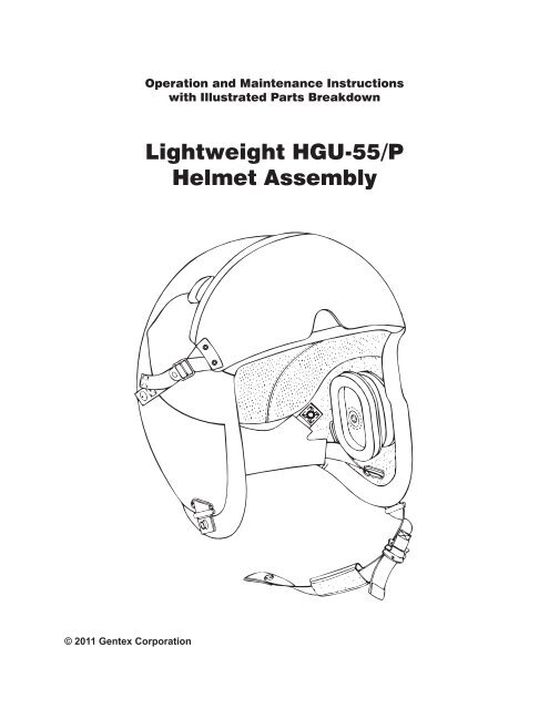
Chapter 1: Introduction and General InformationCHAPTER 1: INTRODUCTION AND GENERAL INFORMATION1-1. GENERALThis chapter provides a description of the <strong>HGU</strong>-<strong>55</strong>/P <strong>Helmet</strong>. It also includes lists of theequipment, tools, and materials needed to maintain the helmet.1-2. HELMET DESCRIPTIONThe <strong>HGU</strong>-<strong>55</strong>/P <strong>Helmet</strong> (Figure 1-1) provides basic head protection, sound attenuation, andcommunications for aircrew personnel. The helmet features a snap-on visor assembly thatprovides facial protection to users from windblast, high light intensity, spall resulting from canopyor wind screen failure, and particles arising from ballistic fragmentation.Figure 1-1. <strong>HGU</strong>-<strong>55</strong>/P <strong>Helmet</strong>1
Chapter 1: Introduction and General Information1-3. HELMET COMPONENTSThe helmet includes the following components, shown in Figure 1-2:<strong>Helmet</strong> Shell. The helmet shell is intended to provide head protection during in-flight buffeting andemergencies such as ejection, bailout, or crash landings. It has a fitted leather edgeroll. Leatherbuffers prevent the visor from scratching the helmet shell. Pile fastener inside the shell holds theearcups in place. Portions of the pile fastener are left detached to allow installation of the oxygenmask bayonet receivers.Energy-Absorbing Liner. The rigid polystyrene energy-absorbing liner absorbs and reducesimpact forces. The liner is held snugly to the inside of the helmet shell by the edgeroll.XLiner® or Thermoplastic Liner (TPL®). The helmet comes with a choice of the XLiner orthe TPL. The XLiner provides a close fit, improved comfort, ease of adjustment, and simplifiedinstallation. It is constructed of anti-microbial, anti-static fabric that also reduces heat buildup insidethe helmet. The preformed TPL consists of a thermoplastic layer assembly (which can be heatedand custom-fitted if necessary) and a removable, washable, ventilated cloth cover. (An optionalSuper Comfort Liner, or SCL, is also available; see Page 56 for details.)Integrated Chin/Nape <strong>Assembly</strong>. The integrated chin/nape assembly, when properly adjusted,stabilizes the helmet during routine flight, bailout, and other high-stress conditions. Tightening thechin strap also tightens the fit of the nape pad. Metal clamps help keep the adjusted chin strapin place.Headset. The headset allows the aircrew member to communicate both inside and outside theaircraft. It also helps protect the ears from hearing loss due to long-term exposure to noise.Included are two earcups (for lateral impact protection and sound attenuation), two 19-ohm H-143/AIC earphones, and a CX-4708A/AIC cable. The earphones are housed inside the earcups andare connected to the cable. A jack holder fastens the cable to the outside of the helmet.Visors. Each helmet includes two snap-on visors (one clear and one sunshade) and a visor cover.<strong>Helmet</strong>-visor configurations are as follows:2• <strong>HGU</strong>-<strong>55</strong>/P helmet with MBU-12/P visors:81D5330-7 (Medium), 81D5330-8 (Large), or 81D5330-9 (X-Large)• <strong>HGU</strong>-<strong>55</strong>/P helmet with high-speed visors:81D5330-13 (Medium), 81D5330-14 (Large), or 81D5330-15 (X-Large)• <strong>HGU</strong>-<strong>55</strong>/P helmet with MBU-20/P visors:81D5330-16 (Medium), 81D5330-17 (Large), or 81D5330-18 (X-Large)Bayonet Receiver Kits. For attachment of the oxygen mask, there are two types of bayonetreceiver kits. The standard bayonet receiver kit is provided with all helmets. The anti-snagreceiver spacer kit is provided with helmet part numbers 81D5330-13, 81D5330-14, and81D5330-15 and includes components to prevent snagging on the bayonet receivers; it is usedwith the bayonet receivers and backing plates from the standard bayonet receiver kit. Both types ofkits include all attaching hardware. The receivers are custom-fitted to each aircrew member.(Other types of bayonet receivers are also available; see Page 59 for details.)
Chapter 1: Introduction and General InformationXLinerTPLVisor cover<strong>Helmet</strong> shellVisorLeather bufferPile fastenerEarcupEnergyabsorbinglinerNape padEarphoneJackholderClampEdgerollClampChin strapCableStandardbayonet receiver kitAnti-snagreceiver spacer kitFigure 1-2. <strong>Helmet</strong> Components3
Chapter 1: Introduction and General Information1-4. EQUIPMENT, TOOLS, AND MATERIALS NEEDEDThis section provides information about the equipment, tools, and consumable materials neededfor helmet preparation and maintenance. Table 1-1 lists the necessary equipment. Table 1-2lists the required tools. Table 1-3 lists the consumable materials used in the preparation andmaintenance of the helmet.Table 1-1. EquipmentITEMLife Support Integrated Tester(LSIT-1/A), G006-1001-01(6695-01-449-4690)MQ-1/MQ1A tester(6695-01-097-0441)DMH-1 tester(6625-01-251-8705)PURPOSETo test the helmet/oxygen mask fit and the headset/oxygenmask communicationsTo test the headset/oxygen mask communicationsTo check communication equipment for shorts or opencircuits; to isolate problem components. Instructionsprovided with each tester.Table 1-2. ToolsITEMCaliperRuler: standard, calibrated ininches to tenths, or metricTorque screwdriverDrill with #25 (5/32”) drill bitUtility knifeJeweler’s screwdriver or1/32 hex wrenchThin, flexible metal spatulaFlat-tip and cross-tipscrewdriversPURPOSETo measure head length, width, and height for determininghelmet size; may be locally manufactured from sheetaluminum, plastic, or cardboardTo obtain the dimensions of the caliper measurements fordetermining helmet sizeTo adjust screws to proper tightness as neededTo drill holes in the helmet shell for the bayonet receiverhardwareTo make X-shaped openings in the pile fasteners inside thehelmet for access to bayonet receiver hardwareTo loosen and tighten earphone set screws duringmaintenanceTo remove energy-absorbing liner during maintenanceTo remove and attach various types of hardware(Continued on next page)4
Chapter 1: Introduction and General InformationTable 1-3. Consumable MaterialsITEMPlastic sheetingPencilAdhesive, polychloroprene(MIL-A-<strong>55</strong>40, Class 3 or equivalent)• Clean, lint free cloths• Chamois (Optional)• Sponge• Mild detergent• Soft scrubbing detergent/cleaner• Saddle soapIsopropyl alcohol (70 percent solution)Thread-locking adhesive(MIL-S-22473, Grade C or equivalent)Aliphatic naphtha• Paint brush• Polyurethane paint, lusterless gray(NSN 8010-01-167-1139)• 320 grit sandpaper• Epoxy filler putty(NSN 8040-00-753-4800)• Putty knife, squeegee, or otherapplicator suitable for epoxy fillerputty• Epoxy primer paint (MIL-P-23377)• Respirator(NSN 4240-01-108-4172) with filterNSN 4240-115-0590 (or equivalent)• Neoprene gloves• Safety glasses or gogglesPURPOSETo make it easier to position the earcups during thehelmet fit checkTo mark the helmet shell for installation of thebayonet receiversTo attach the loose portion of the helmet pilefasteners after the bayonet receivers are installedTo clean various helmet componentsTo clean the visorTo apply to bayonet receiver screws duringinstallation or replacementTo clean the helmet shell or bayonet receivers inpreparation for paintingTo paint the helmet and/or bayonet receiversTo wear for protection during the painting process5 (6 blank)
Chapter 2: <strong>Helmet</strong> Preparation and OperationCHAPTER 2: HELMET PREPARATION AND OPERATION2-1. GENERALThis chapter includes instructions for the tasks required to prepare the helmet for use. Thesetasks include helmet fitting, familiarizing the aircrew member with the operation of the helmet,and installing bayonet receivers. There is also a summary of operational tasks at the end of thechapter.2-2. HELMET FITTINGProper fitting of the helmet is imperative for the safety of the aircrew member. Animproperly fitted helmet can become unstable (failing to provide bump protection),or it can be lost during a high-speed ejection (causing injury to the aircrew member).Ensure that the helmet is properly fitted to the aircrew member.A properly fitted helmet is much more likely to remain on the head during a high-speed ejection,minimizing the risk of injury. The helmet should provide protection and stability in emergencyejections up to 600 knots indicated airspeed (KIAS). A properly fitted helmet also aids inmaintaining the stability of helmet-mounted devices such as night vision goggles. In addition,a proper fit ensures a comfortable helmet (no pressure points) and is less distracting duringhigh-G maneuvers.This section provides instructions for the tasks involved in ensuring a proper helmet fit. Thesetasks include:• 2-2.1 Determining <strong>Helmet</strong> Size (Page 8).• 2-2.2 Fitting the TPL, SCL, or XLiner (Page 9)• 2-2.3 Checking <strong>Helmet</strong> Fit and Operation (Page 10).7
Chapter 2: <strong>Helmet</strong> Preparation and Operation2-2.1. Determining <strong>Helmet</strong> SizeTo determine helmet size, you measure the aircrew member's head length and head width.After you make these measurements, you then compare the measurements to established sizedata and select the helmet size accordingly.Proper fitting of the helmet is imperative for the safety of the aircrew member. Animproperly fitted helmet can become unstable (failing to provide bump protection),or it can be lost during a high-speed ejection (causing injury to the aircrew member).Ensure that the helmet is properly fitted to the aircrew member.Tools/Equipment/Materials Needed• Caliper (Figure 2-1); used to measure head length and width; may be locally manufacturedfrom sheet aluminum, plastic, or cardboard• Ruler calibrated in inches to tenths (or metric); used to obtain the dimensions of the calipermeasurements(Continued on next page)1/ 4inch (6 mm) R4 1 / 16inches (104 mm)1/ 2inch (13 mm)10 inches (254 mm)30°1 1 / 8inches(29 mm) R1 15 / 16inches(49 mm)3 7 / 8inches (98 mm)Figure 2-1. Caliper8
Chapter 2: <strong>Helmet</strong> Preparation and OperationMeasuring Head LengthMeasure the aircrew member's head length as follows:1. Use a caliper and a ruler as shown in Figure 2-2to measure the distance (to the nearest .1 inchor 2.5 mm) from the point between the eyebrowsto the back of the head. This is the head length.Ensure that the caliper touches the skin lightlyand does not indent the skin surface.POINTS TOMEASUREMeasurementpoint at backof headCaliperMeasurementpoint betweeneyebrowsRuler2. Record the measurement.Measuring Head WidthMeasure the aircrew member's head width as follows:1. Use a caliper and a ruler as shown in Figure 2-3to measure the maximum horizontal width (to thenearest .1 inch or 2.5 mm) of the head abovethe ears. This is the head width. Ensure thatthe caliper touches the skin lightly and does notindent the skin surface.2. Record the measurement.Selecting <strong>Helmet</strong> Size Based on MeasurementsFigure 2-2. Head LengthMaximum horizontal widthCaliperPOINTS TOMEASURERulerFigure 2-3. Head WidthCompare the head length and head width measurements to the sizing parameters shown inTable 2-1, and select the helmet size.NOTES:• The dimensions shown in Table 2-1 are intended as guidelines. At times, the next smaller orlarger size may be needed.• If the measurements fall into different size ranges, select the larger size.Table 2-1. Size Data for <strong>HGU</strong>-<strong>55</strong>/PHead Length, inches (mm) Maximum Head Width, inches (mm) <strong>Helmet</strong> Size7.2 to 7.8 (183 to 198)6.2 (157)Medium7.7 to 8.3 (195 to 211)8.2 to 8.7 (208 to 221)6.5 (165)6.8 (173)LargeX-Large2-2.2. Fitting the TPL, SCL, or XLiner• TPL: Refer to TP0008.• SCL: Refer to TP0236.• XLiner: Refer to TP0265.9
Chapter 2: <strong>Helmet</strong> Preparation and Operation2-2.3. Checking <strong>Helmet</strong> Fit and OperationOnce you have determined the correct helmet size and custom-fitted the TPL, you must ensurethat the helmet is properly fitted and adjusted to the aircrew member, as well as familiarize theaircrew member with proper helmet operation.Proper fitting of the helmet is imperative for the safety of the aircrew member. Animproperly fitted helmet can become unstable (failing to provide bump protection),or it can be lost during a high-speed ejection (causing injury to the aircrew member).Ensure that the helmet is properly fitted to the aircrew member.Tools/Equipment/Materials Needed• Small cross-tip screwdriver; used to adjustthe attaching hardware on the helmet• Plastic sheeting; used to make it easier toposition the earcups as the aircrew memberwears the helmet• Torque screwdriver; used to adjust thenape strap clamp screws to the propertightnessProcedure1. Referring to Figure 2-4, loosen (do notremove) the two screws on each napestrap clamp. Move both clamps downas far as possible on the straps to provideslack during the fitting process.ClampScrewsENLARGED VIEW OF CLAMPFigure 2-4. Nape Strap Clamps2. Temporarily insert a piece of paper orplastic between each earcup and the pilefaster inside the helmet (to make it easierto reposition the earcups).3. Holding the earcups in place inside thehelmet, assist the pilot in donning thehelmet (Figure 2-5).4. Reposition the earcups until the ears arecentered within the earcups.(Continued on next page)Figure 2-5. Donning <strong>Helmet</strong>10
Chapter 2: <strong>Helmet</strong> Preparation and Operation5. Have the pilot fasten and adjust thechin strap as follows (Figure 2-6):a. Snap the chin strap.b. Adjust the end of the chin strapso that the nape pad fits snuglyagainst the back of the head.c. Center the chin pad under thechin. Attach the end of the chinstrap to the chin pad.6. Referring to Figure 2-7, checkthe height from the edge of thehelmet to the aircrew member'seye pupils. This height should beapproximately 1½ inch ±¼ inch(38 mm ±6 mm) for maximum fieldof view.If the height is correct, go to Step11 (next page).Chin padEnd of chin strapSnapNape pad(inside helmet)LOWER FRONT VIEW OF HELMETFigure 2-6. Fastening Chin StrapBuckleIf the height is not correct, performStep 7.7. Attempt to adjust the height byrotating the helmet forward orrearward as applicable. Readjustthe chin strap. Perform Step 8.8. Check the height as in Step 6.If the height is correct, go to Step11 (next page).If the height is not correct, performSteps 9 and 10.Figure 2-7. Measuring <strong>Helmet</strong> Height9. Re-fit the TPL, SCL, or XLiner (Paragraph 2-2.2). Then perform Step 10.10. Check the height of the helmet as in Step 6.If the height is correct, go to Step 11 (next page).If the height is not correct, obtain a helmet of a different size and return to Step 1.(Continued on next page)11
Chapter 2: <strong>Helmet</strong> Preparation and Operation11. Confirm that the pilot is comfortable while wearing the helmet.If the pilot is comfortable, proceed to Step 12.If the helmet is too tight, or pressure points exist, re-fit the TPL, SCL. or XLiner(Paragraph 2-2.2).If the helmet is too loose, obtain a smaller-size helmet return to Step 1 (Page 10).12. Check the compression of the earseals against the pilot's ears. For best communication,hearing protection, and comfort, the earseals should be compressed to approximately halfof their original thickness.If the earseals are sufficiently compressed, continue to Step 14.If the earseals are not sufficiently compressed, go to Step 13.13. Have the pilot remove the helmet.Referring to Figure 2-8, attach one ormore fitting pads to the back of eachearcup. Then continue to Step 14.NOTE: You can install the fitting padswhole or cut them to any size or shapenecessary to achieve the best fit.14. Check the fit of the nape pad. It shouldfit as snugly as possible without causingdiscomfort. Adjust the fit as necessary bytightening the chin strap.Fitting padEarcupEarsealFigure 2-8. Earcup and Fitting Pad15. Ensure that the pilot is comfortable.CAUTIONWhen you perform Step 16, do not tightenthe screws too much, or the clamps willcrack.16. With the nape pad properly adjusted,move both clamps (Figure 2-9) up thestraps as far as possible, and tighten thescrews on the clamps to a torque value of22 ±2 inch-ounces (in.oz), or 15.5 ±1 centiNewton meters (cNm).(Continued on next page)ENLARGED VIEW OFCLAMP (BOTH SIDES)ClampFigure 2-9. ClampsScrews12
Chapter 2: <strong>Helmet</strong> Preparation and Operation17. Check the overall fit; the helmet should besnug, yet comfortable. Attempt to rock thehelmet back and forth on the head; thehelmet should not move.If the fit is correct, go to Step 18.If the helmet moves, it may be too loose.Obtain a smaller size and return to Step 1(Page 10).18. If not already done, snap the visor to thehelmet (Figure 2-10). Fasten each snapfrom front to back. Adjust the visor for asnug fit to the helmet.MBU-12/P orMBU-20/P Visorand <strong>Helmet</strong>Plastic spacerIf the pilot wears a high-speed helmet(which includes an installed edgerollcover), use ONLY a high-speed visor(which includes plastic spacers nearthe straps); see Figure 2-10. Use of anyother visor type will not provide 600-knot capability and may cause a loss ofthe visor or the helmet during ejection.19. Referring to Figure 2-11, operate thevisor as follows:High-Speed Visorand <strong>Helmet</strong>VISOR COVERINSTALLATIONCoverEdgeroll coverFigure 2-10. Installing Visora. Grasp the visor in the center and pullit slightly away from the helmet.b. Move the visor up or down. When thevisor is up, ensure that its top edge isagainst the two bump stops.c. Adjust the visor straps to center thevisor over the nose. Ensure thatthe visor is snug enough; it shouldnot slide freely up and down. Thereshould be enough resistance torequire pulling the visor away from thehelmet to raise or lower it.NOTE: When the visor is up, you canattach the visor cover. Press the hookfasteners on the cover to the pile fasteneron the visor.(Continued on next page)Figure 2-11. Operating VisorBump stop(both sides)Strap(both sides)13
Chapter 2: <strong>Helmet</strong> Preparation and Operation20. With the helmet stillon the pilot's head,remove the plasticsheeting from behindthe earcups.21. If the chin strap istoo long after it isadjusted, mark atrim line at the endof the chin strapapproximately2 inches (5 cm)from the edgeas shown inFigure 2-12.ENLARGED VIEW,END OF CHIN STRAPTrim line2 in. (5 cm)Figure 2-12. Marking Trim Line on Chin Strap22. If you marked the chin strap (Step 21), trim the chin strap as follows:d. Unsnap the chin strap; have the aircrew member remove the helmet.e. Unlace the other end of the chin strap from the buckle.f. Note the orientation of the chin pad, and remove the chin pad from the chin strap.g. Cut the strap at the trim line.h. Sear the cut edge to prevent the strap from unraveling.i. Fold the cut end of the chin strap under (doubled 1/4 inch, or 6mm) and stitch the foldusing thread (waxed black MIL-T-83193), 10 to 12 stitches per inch (2.54 cm).j. Replace the hook fastener (Figure 2-13) with 1 inch (2.54 cm) of hook fastener (NSN8315-01-445-8812) using thread (MIL-T-83193), 10 to 12 stitches per inch (2.54 cm).k. Slide the chin pad onto the chin strap, ensuring that it is oriented correctly.l. Lace the chin strap through the buckle.Trim line1 in. (2.54 cm)hook fastenerFigure 2-13. Trimming Chin Strap14
Chapter 2: <strong>Helmet</strong> Preparation and Operation2-3. BAYONET RECEIVER INSTALLATIONThe standard bayonet receiver kit (Paragraph 2-3.1) is included for installation on all helmetconfigurations. The anti-snag bayonet receiver kit (Paragraph 2-3.2) is included for installationon helmet part numbers 81D5330-13, 81D5330-14, and 81D5330-15 and is designed to preventthe helmet bayonet receivers from snagging on objects.NOTE: An optional anodized black bayonet receiver is also available; see Page 59 for details.2-3.1. Installing Standard Bayonet ReceiversThe standard bayonet receivers are individually fitted to the aircrew member. Before youinstall the receivers, you must ensure that the helmet has been properly fitted as described inParagraphs 2-2.1, 2-2.2, and, 2-2.3. You will also familiarize the aircrew member with maskattachment in this procedure.Tools and Equipment Required• Pencil• Drill with #25 (5/32") drill bit• Small cross-tip screwdriver• Adhesive, polychloroprene MIL-A-<strong>55</strong>40, Class 3 or equivalent• Utility knife• Standard bayonet receiver kit (82A5614-10)Before you begin this procedure, referto Figure 2-14 and ensure that youhave the following components of thestandard bayonet receiver kit:Bayonet receiversScrews• Two bayonet receivers• Two spacers• Four screws• Four lock washers• Two backing platesNOTE: If the aircrew member hasworn the oxygen mask with a helmetother than the one being fitted withreceiver assemblies, check the maskstraps. New straps may be needed tomaintain the helmet offset measuredduring helmet fitting. This allows thehelmet to be positioned correctly on thecrewmember’s head during bayonetreceiver installation.SpacersWashersBacking plates(Continued on next page)Figure 2-14. Standard Bayonet Receiver Kit15
Chapter 2: <strong>Helmet</strong> Preparation and OperationProcedureInstall the bayonet receiver parts on the helmet as follows:1. Raise the visor; have the aircrew member don the properly fitted helmet.2. Insert the mask bayonets into the bayonet receivers to the second locking position.Ensure that all straps are fully extended, have equal tension, and flow smoothly from themask to the facepiece and the bayonets.CAUTIONWhen performing Step 3, do notposition the bayonet receiverson top of the edgeroll. Improperfunction, jamming, or damageto the hardware may result if thebayonet does not lie flat againstthe helmet shell.3. Center the oxygen mask onthe aircrew member’s face.Lower the visor to check theinterface between the visorand the mask.4. With the mask and the helmetsymmetrically positioned,place the bayonet receiver onthe helmet with the projectionfacing aft as shown inFigure 2-15. Ensure that thenumbered side of the receiverfaces the helmet shell.Figure 2-15. Positioning Bayonet Receiver5. Hold the receiver firmlyagainst the helmet. Referringto Figure 2-16, trace lightlyaround the receiver with apencil. Repeat for the otherside.6. Remove the receivers and themask from the helmet; havethe aircrew member removethe helmet.PilotTechnician(Continued on next page)Figure 2-16. Tracing Outline of Bayonet Receiver16
Chapter 2: <strong>Helmet</strong> Preparation and Operation7. Referring to Figure 2-17, carefullyalign the receiver within the tracedoutline and mark the two screwholes for drilling. Repeat for theother side.8. Referring to Figure 2-18,detach the earcups from the pilefasteners, and peel back the pilefasteners.When drilling (Step 9), keep yourhands away from the drill bit toavoid injury.Figure 2-17. Marking Hole LocationsCAUTIONWhen drilling (Step 9), hold thedrill perpendicular to the helmet toprevent damage.Pile fastenerpeeled back(both sides)NOTES:• If necessary, peel the edgeroll awayin the earcup area to protect it fromthe drill bit.• It is advisable to drill pilot holes,using a #52 (1/16") drill bit, beforedrilling full-size holes.Earcupdetached(both sides)Figure 2-18. Earcup and Pile FastenerOutline9. Ensuring that the pile fastenerinside the helmet is not in thedrilling area, drill both the rightand the left marked hole locationswith a #25 drill bit (Figure 2-19.)10. Carefully remove any frayed fibersresulting from drilling.(Continued on next page)Figure 2-19. Drilling Holes17
Chapter 2: <strong>Helmet</strong> Preparation and Operation11. Referring to Figure 2-20, do the following:CAUTIONIn Step 11, do not tighten either screw in the receiver until both screws have been started,or you might cross-thread the receiver assembly.a. Insert the screws through the lock washers and the backing plate in that order.b. On the inside of the helmet, position the backing plate against holes; insert the screwsthrough the holes.c. On the outside of the helmet, position the spacer and the receiver over the screws withthe projections pointed toward the helmet rear. Ensure that the numbered side of thereceiver faces the helmet. Tighten the screws into the spacer and receiver.d. Repeat Steps a-c on the other side of the helmet.12. Apply a thin, even coat of polychloroprene adhesive to both the inside surface of thehelmet shell earcup areas and the back of the earcup pile fastener material. Do notallow the adhesive to contact the backing plates, the screws, or the retention assemblyhardware. Allow the adhesive to dry approximately two minutes or until tacky.13. Press the earcup pile fastener material firmly againstthe shell surface. Allow the adhesive to set at least 15minutes; ideally, you should allow it to set overnight.14. Use a utility knife to cut an "X" pattern throughthe pile fastener over each screw head. This willfacilitate inspection, tightening, or replacement of thehardware.15. Reinstall the earcups and the visor.16. Have the aircrew member don the helmet. Re-checkthe helmet fit as described in Paragraph 2-2.3 andmake any needed adjustments.17. Have the aircrew member don the mask. Check themask for proper position and tension in accordancewith applicable oxygen mask technical orders. Checkthe interface between the visor and the mask. Adjustthe mask straps as required.18. Connect the mask cord to the helmet connector(Figure 2-21).NOTE: To remove the mask cord from the helmetconnector, pull firmly on the cord plug.ScrewsLock washersBacking plateSpacerBayonet receiverFigure 2-20. Installing KitMaskcord<strong>Helmet</strong>connectorFigure 2-21. Connecting Cord18
Chapter 2: <strong>Helmet</strong> Preparation and Operation2-3.2. Installing Anti-Snag Receiver Spacer KitThe anti-snag receiver spacer kit is intended for installation on helmets that already have thestandard bayonet receiver kit installed. Before you install the receivers, you must ensure thatthe helmet has been properly fitted as described in Paragraphs 2-2.1, 2-2.2, and, 2-2.3; and thatthe standard bayonet receiver kit has been installed as described in Paragraph 2-3.1. You willalso familiarize the aircrew member with mask attachment in this procedure.Tools and Equipment Required• Pencil• Drill with #25 (5/32") drill bit• Small cross-tip screwdriver• Adhesive, polychloroprene MIL-A-<strong>55</strong>40, Class 3 or equivalent• Utility knife• Anti-snag bayonet receiver kit (05A12024-1)Before you begin this procedure, refer toFigure 2-22 and ensure that you havethe following components of the anti-snagreceiver spacer kit:• Two anti-snag spacers• Two 5/16" MS51957-27B screws• Four 1/2" MS51957-30B screws• Six lock washersAnti-snag spacersScrews, MS51957-27BScrews, MS51957-30BNOTE: If the aircrew member has worn theoxygen mask with a helmet other than the onebeing fitted with receiver assemblies, checkthe mask straps. New straps may be neededto maintain the helmet offset measured duringhelmet fitting. This allows the helmet to bepositioned correctly on the aircrew member’shead during bayonet receiver installation.Lock washersFigure 2-22. Anti-Snag Receiver Spacer KitProcedure1. Detach both earcups from the pile fasteners inside the helmet. Position the earcups clearof the work area.2. If the interior screws for the bayonet receivers are not accessible, peel back both pilefasteners from the inside of the helmet to provide access to the screws of the existingbayonet receivers. Position the peeled-back portions clear of the work area.(Continued on next page)19
Chapter 2: <strong>Helmet</strong> Preparation and Operation3. Referring to Figure 2-23, removethe two screws, the two washers,and the backing plate from theinside of the helmet to detachthe existing bayonet receiverassembly and the spacer on oneside of the helmet. Discard thespacer, screws, and washers; youwill replace them with new ones.4. Repeat Step 3 for the other side ofthe helmet.NOTE: Keep the bayonetreceivers and backing plates forreinstallation.ScrewsLock washersBacking plateSpacerBayonet receiverFigure 2-23. Bayonet Receiver <strong>Assembly</strong>NOTE: The kit includes left-handand right-hand anti-snag spacers.Ensure that you are using thecorrect spacer for the side ofthe helmet on which it is beinginstalled. Figure 2-24 shows theright-hand spacer on the righthandside of the helmet (as worn).Anti-snagspacerHoles to line upGrommet5. Mark the top spacer hole asfollows:a. On one side of the helmet,align the holes of the antisnagspacer (Figure 2-24)over the bayonet receivermounting holes in the helmet.(If necessary, adjust the angleof the spacer to eliminateinterference with the chinstrapor the grommet.)Holes in helmetChin strapFigure 2-24. Aligning Anti-Snag SpacerHole to markb. Mark the helmet throughthe top hole in the anti-snagspacer (Figure 2-25).c. Repeat Steps a and b to markthe upper hole in the otheranti-snag spacer on the otherside of the helmet.(Continued on next page)Figure 2-25. Marking Top Hole20
Chapter 2: <strong>Helmet</strong> Preparation and OperationWhen drilling, position your hands away from the drill bit to avoid injuryCAUTIONWhen drilling, hold the drill perpendicular to the helmet to prevent damage.NOTE: Before drilling full-size holes in thehelmet shell, it is advisable to drill pilot holeswith a #52 (0.0625") drill bit.Hole to drill6. Referring to Figure 2-26, use a drill with a #20(0.161") bit to drill both upper holes marked inStep 5.7. Referring to Figure 2-27, attach the kit asfollows:a. On one side of the helmet, align the antisnagspacer over the holes, ensuring allthree holes line up.b. Align the bayonet receiver over the antisnagspacer, ensuring that the four rivets inthe bayonet receiver are seated within thefour holes in the spacer.c. From inside the helmet, attach thebayonet receiver and the spacer using thebackplate, washers, and MS51957-30Bscrews. Ensure that the edgeroll is trimmedor pushed back so that the backplate will lieflush against the inside of the helmet.Figure 2-26. Drilling Marked Hole*NOTE: For clarity, only one screwand washer are shown for thebayonet receiver assembly.There are actually two.Screw, MS51957-30*Washer*Backing plateScrew, MS51957-27Bd. Install the MS51957-27B screw and washerinto the anti-snag spacer where the holewas drilled in Step 4. Tighten the screw tono more than 60 inch-ounces of torque.Ensure that each screw is rotated at leastthree turns so that it is properly engaged inthe bayonet receiver.e. Repeat Steps a-d on the other side of thehelmet.Anti-snagspacerBayonetreceiverWasher(Continued on next page)Figure 2-27. Attachment of Kit21
Chapter 2: <strong>Helmet</strong> Preparation and Operation8. Apply a thin, even coat of polychloroprene adhesive to the back of the peeled-awayportion of both pile fasteners and to the inside surface of the helmet shell where the pilefasteners were peeled away. Do not allow the adhesive to contact the backing plates, thescrews, or the retention assembly hardware. Allow the adhesive to dry approximately twominutes or until tacky.9. Press the pile fasteners firmly against the shell surface. Allow the adhesive to set at least15 minutes; ideally, you should allow it to set overnight.10. Use a utility knife to cut an "X" pattern in the pile fasteners over the screws. This will permitfuture inspection and tightening of the screws.11. Reattach both earcups to the pile fasteners.12. Reinstall the visor.13. Have the aircrewmember don thehelmet. Re-check thehelmet fit as describedin Paragraph 2-2.3and make any neededadjustments.14. Have the aircrewmember don the mask.Check the mask forproper position andtension in accordancewith applicable oxygenmask technical orders.Check the interfacebetween the visorand the mask. Adjustthe mask straps asrequired.15. Connect the maskcord to the helmetconnector, shown inFigure 2-28.NOTE: To remove themask cord from the helmetconnector, pull firmly on thecord plug.Maskcord<strong>Helmet</strong>connectorFigure 2-28. Connecting Mask Cord22
Chapter 2: <strong>Helmet</strong> Preparation and Operation2-4. OPERATIONThis section contains a summary of the helmet operational tasks described in the fitting andinstallation sections of this chapter. Operational tasks include donning the helmet, fastening andadjusting the chin strap, operating the visor, and connecting the mask microphone cord to thehelmet connector.2-4.1. Donning <strong>Helmet</strong>Don the helmet as follows:1. Grasp the helmet in the earcupareas.2. Referring to Figure 2-29, placethe front of the helmet against theforehead, and rotate the helmettoward the rear and down onto thehead.3. Ensure that the ears are centeredin the earcups.Figure 2-29. Donning <strong>Helmet</strong>2-4.2. Fastening Chin StrapFor the safety of the aircrew member,the chin strap must remain firmlysecured at all times of flight. Thisprevents helmet rotation duringhigh-G maneuvers, or loss of helmetduring emergency ejectionNape pad(inside helmet)Referring to Figure 2-30, fasten andadjust the chin/nape assembly asfollows:1. Snap the chin strap.2. Pull on the end of the chin strap toadjust it for a snug fit.3. Attach the end of the chin strapsecurely to the pile fastener on thechin pad.Chin padEnd of chin strapSnapBuckleLOWER FRONT VIEW OF HELMETFigure 2-30. Fastening Chin Strap23
Chapter 2: <strong>Helmet</strong> Preparation and Operation2-4.3. Operating VisorOperate the visor as follows:1. Referring to Figure 2-31, grasp thevisor in the center and pull the visorslightly away from the helmet.VISOR COVERINSTALLATIONCover2. Move the visor up or down. Whenthe visor is up, ensure that the topedge of the visor is against the twobump stops.3. As necessary, adjust the visor strapsso that the visor is centered over thenose. Ensure that the visor is snugenough. The visor should not slidefreely up and down. There should beenough resistance to require pullingthe visor away from the helmet toraise or lower it.NOTE: When the visor is up, youcan attach the visor cover bypressing the hook fasteners on thecover to the pile fastener on thevisor.Figure 2-31. Operating VisorBump stop(both sides)Strap(both sides)2-4.4. Connecting Mask MicrophoneCord to <strong>Helmet</strong> ConnectorWith the helmet donned and properlyadjusted, do the following:1. Don the mask. Check the maskfor proper position and tension inaccordance with applicable oxygenmask technical orders. Check theinterface between the visor and themask. Adjust the mask straps asrequired.2. Connect the mask cord to the helmetconnector, shown in Figure 2-32.NOTE: To remove the mask cord from thehelmet connector, pull firmly on the cordplug.Maskcord<strong>Helmet</strong>connectorFigure 2-32. Connecting Mask Cord24
Chapter 3: <strong>Helmet</strong> MaintenanceCHAPTER 3: HELMET MAINTENANCE3-1. GENERALThis chapter provides instructions for the task required to maintain the helmet. These tasksinclude inspection, cleaning, replacing components, and repainting.3-2. INSPECTIONSProper care and use of the <strong>HGU</strong>-<strong>55</strong>/P helmet assembly is essential to ensure optimumperformance during emergencies and routine operations. The helmet must be inspected atregular intervals to ensure that it is in serviceable condition. These intervals are describedbelow.3-2.1. Inspection Upon ReceiptUpon receipt of the helmet, inspect the helmet as follows:1. Remove the helmet from the shipping container. Retain the container for shipment, ordispose of it as applicable.2. Inspect the helmet for any damage incurred during shipment, such as breaks or cuts in thehelmet shell, or scratches or cracks in the visor.3. Replace all damaged parts to make the helmet serviceable.4. Report all deficiencies to a supervisor or quality assurance manager to resolve.3-2.2. Pre-Flight InspectionBefore each flight, the user shall inspect the helmet to ensure that it is serviceable. Perform thepre-flight inspection as follows:Any crack that has broken through the layers of helmet shell material (not just thepaint surface) will affect the integrity of the helmet. Discard a helmet with such cracks.1. Check the helmet shell for cracks that have broken through the layers of helmet shellmaterial. (Minor cracks in the paint surface are acceptable.)2. Ensure that the helmet and the oxygen mask have been properly fitted.(Continued on next page)25
Chapter 3: <strong>Helmet</strong> Maintenance3. Ensure that the chin strap and nape strap have been properly adjusted for a snug fit andare securely attached to the helmet shell.Cracks in the visor are not acceptable. Cracks will weaken the visor and may causethe visor to fail, creating additional hazards during ejection.4. Ensure that the visors are free of cracks, scratches, dust, and smears. (Minor scratchesthat do not interfere with vision are acceptable.)5. Ensure that the visors are securely attached to the helmet.6. Ensure that the visors can be raised and lowered easily and that they lock in placesecurely.7. Ensure that the headset components are securely attached and are working properly. Youcan perform checkout by plugging the mask microphone cable into the MQ-1/MQ1A tester,DMH-1 tester, or another tester while the mask microphone is connected to the helmetheadset. Speak into the microphone. The microphone and earphones are working whenthe voice is transmitted through the amplifier and is heard through the headset.8. Ensure that the energy-absorbing liner is securely attached to the helmet and is free ofholes and cracks.9. Ensure that the TPL or XLiner is securely attached, properly fitted, and free of holes ortears.10. Check the general condition of all attaching hardware.11. Inspect the oxygen mask and associated components for general condition as required bythe appropriate technical manual.3-2.3. Post-Flight InspectionPost-flight inspection is to be performed as designated following the last flight of the day. Thehelmets will be stored in a designated area, normally the life support shop. Perform the postflightinspection as follows:Any crack that has broken through the layers of helmet shell material (not just thepaint surface) will affect the integrity of the helmet. Discard a helmet with such cracks.261. Check the helmet shell for cracks that have broken through the the helmet shell material.(Minor cracks in the paint surface are acceptable.)
Chapter 3: <strong>Helmet</strong> Maintenance2. Inspect the edgeroll for loose edges or damage such as cuts, tears, or holes.NOTE: Advise the aircrew member not to set the helmet on the canopy edge, boardingladders, or pylons to prevent damage to the leather edgeroll.3. Check the helmet for loose screws.4. Ensure that the visors are free of cracks, scratches, dust, and smears. (Minor scratchesthat do not interfere with vision are acceptable.)NOTE: Wipe the visor with a chamois or clean, non-scratching cloth. You may moistenthe cloth with a 70% isopropyl alcohol/water mix to remove oil or grease smears from thevisor.5. Ensure that the visor is securely attached to the helmet.6. Ensure that the visor fits the helmet snugly, with enough resistance to require pulling thevisor away from the helmet to raise or lower it.7. Ensure that the headset components are securely attached and are working properly. Youcan perform checkout by plugging the mask microphone cable into the MQ-1/MQ1A tester,DMH-1 tester, or another tester while the mask microphone is connected to the helmetheadset. Speak into the microphone. The microphone and earphones are working whenthe voice is transmitted through the amplifier and is heard through the headset.8. Ensure that the energy-absorbing liner is securely attached to the helmet and is free ofholes or damage.9. Ensure that the TPL or XLiner is securely attached, properly fitted, and free of holes andcracks.10. Check the general condition of all attaching hardware.3-2.4. Periodic InspectionAircrew members are responsible for ensuring that their helmets have been inspected, cleaned,and repaired as necessary by certified Life Support Technicians within 30 days before eachflight. <strong>Helmet</strong>s used without oxygen masks shall be inspected within 90 days before each flight.<strong>Helmet</strong>s used only with the aircrew chemical defense ensemble shall be inspected every 180days before each flight. Inspections shall be annotated on an appropriate form as a record ofinspection and maintenance. A piece of pressure-sensitive tape may be attached to the helmet/oxygen mask to record inspection dates.(Continued on next page)27
Chapter 3: <strong>Helmet</strong> MaintenanceNOTES:• As a result of this inspection, any component found to be defective will be repaired orreplaced as necessary.• If any items are to be replaced, refitting of the helmet and mask may be necessary.Perform the periodic inspection as follows:1. Visually inspect the helmet shell for cleanliness, warping, holes, cracks, and scratches.2. Inspect the leather edgeroll and visor buffers for holes, cuts, torn seams, or loose areas.3. Inspect the TPL or XLiner for cleanliness. Replace the TPL cloth cover if it is too soiled toclean, or gently hand-wash the XLiner.4. Inspect the energy-absorbing liner for damage such as gouges, depressions, or evidenceof erosion from solvents. Replace the energy-absorbing liner if there is reasonableassumption that the damage is sufficient to compromise head protection.5. Inspect the hook fasteners on the energy-absorbing liner to ensure that they are securelyadhered to the liner and that they hold the TPL or XLiner securely.6. Inspect the chin strap and the nape strap to ensure that the fabric and stitching are nottorn; and that the chin strap buckle is not corroded, bent, or broken.7. Inspect the attaching hardware of the chin strap and the nape strap for security ofattachment (tightness) and corrosion. Ensure that the washers are properly positioned.8. Inspect the earpads for secure attachment, cleanliness, cuts, tears, or other damage thatcould compromise safety or sound attenuation.9. Inspect the cable for breaks or frayed areas.10. Inspect the rubber grommet and the connector bracket for secure attachment to thehelmet shell.11. Plug the microphone cable and plug assembly into the MQ-1/MQ-1A tester or DMH-1tester and ensure that the microphone and earphones are working properly.CAUTIONVisors have an abrasion-resistant coating, but they can still be scratched with improperhandling. Handle the visors with care.12. Ensure that the visors are free of cracks, scratches, dust, and smears. (Minor scratchesthat do not interfere with vision are acceptable.)28
Chapter 3: <strong>Helmet</strong> MaintenanceProcedureClean the helmet as follows:1. <strong>Helmet</strong> shell: Clean with mild detergent and clean cloth; for stains, use a soft-scrub type ofdetergent or equivalent. Do not use waxes or solvents as they may deteriorate the paint ordamage the helmet.2. Cable and connector: Wipe with damp cloth; dry thoroughly.CAUTIONVisors have an abrasion-resistant coating, but they can still be scratched with improperhandling. Handle the visors with care.3. Visors: Clean with a soft cloth and a mild soap solution; rinse with clean water, OR use aclean, lint-free cloth dampened with a 70 percent solution of isopropyl alcohol. You mayalso use a chamois.4. Chin strap and nape strap webbing: Wipe with a clean cloth dampened with a mild soapsolution; allow to dry thoroughly.5. Leather components (edge roll, earpad, chin pad, nape pad): Apply a small amount ofsaddle soap with a damp sponge. Rub vigorously to generate a thin soap film. Wipe with aclean cloth and allow to dry overnight.6. TPL or SCL: Do the following:a. Remove the TPL or SCL from the helmet.b. Referring to Figure 3-1, note the manner in which the cloth cover is installed on theplastic layers. (The holes in the plastic layers and the label on the cloth cover areat the same end.) Fold the sides of the cover down, and remove the cover from theplastic layers.c. Hand-wash the cover with mild detergent only, and allow it to dry.d. Referring to Figure 3-1, place the plastic layers over the clean, dry cover, ensuring thatthe cover will be installed properly (not backwards). Fold the sides of the cloth coverover the plastic layers.e. Referring to Figure 3-2, reinstall the TPL or SCL into the helmet.7. XLiner: Remove from the helmet; gently hand-wash with mild detergent; rinse thoroughlyand allow to dry flat. Do not place in dryer. Do not wring. Do not use bleach or machinedetergents. Reinstall the XLiner into the helmet as described in TP0265.30
Chapter 3: <strong>Helmet</strong> MaintenanceCoverCover on layersCover installedHole(two places)LabelFigure 3-1. Installing TPL or SCL CoverFigure 3-2. Installing TPL or SCL into <strong>Helmet</strong>CAUTION• Prolonged exposure to excessive heat can damage the TPL or SCL. Do not store thehelmet in a closed cockpit or automobile where temperatures can exceed 200ºF (93.3ºC)on an 85ºF(30ºC) day.• The TPL or SCL cover can be hand-washed only. Use mild detergent only, no bleaches ormachine detergents.• Do not put the TPL or SCL cover in the dryer.31
Chapter 3: <strong>Helmet</strong> Maintenance3-4.2. Replacement of EarsealsParts RequiredEarseals (75C2990)Tools/Materials RequiredNoneProcedureReferring to Figure 3-4, replace the earseals as follows:1. Detach the earcups from the pile fasteners inside the helmet.2. Note how the existing earseals are installed on the earcups; then remove the earsealsfrom the earcups.3. Stretch the replacement earseals over the earcups in the same manner in which theprevious earseals were installed.4. Reattach the earcups to the pile fasteners.5. Check earcup position as described in Paragraph 2-2.3, and make any necessaryadjustments.Pile fastenerEarsealEarcupFigure 3-4. Earcup Detached33
Chapter 3: <strong>Helmet</strong> Maintenance3-4.3. Replacement of Earcups or EarphonesParts RequiredEarcups (80C4758), quantity of 2orEarphones (69B2032), quantity of 2Tools/Materials Required• Jeweler’s screwdriver• Isopropyl alcohol (70 percent solution) or soap and waterProcedure1. Referring to Figure 3-5, pull the earphone out the earcup as follows:a. Detach one earcup from the pile fastener inside the helmet.b. Remove the earphone holder from the earcup.Optional: You may also remove the earseal from the earcup to ease the removal ofthe earphone holder.c. Remove the earphone from the earphone holder.(Continued on next page)Pile fastenerEarphone holderEarphoneEarsealEarcupFigure 3-5. Earphone Removed from Earcup34
Chapter 3: <strong>Helmet</strong> Maintenance2. Referring to Figure 3-6, disconnect theearphone from the cable as follows:a. Use a jeweler’s screwdriver toloosen (not remove) the set screwson the back of the earphone.b. Withdraw the cable leads from theearphone.NOTE: Ensure that the metal stay onthe cord does not contact the earcupgrommet; this will hinder the removal ofthe grommet.GrommetCableEarcupEarphoneSet screwsc. If you are replacing the earcup,remove the small rubber grommetfrom the hole in the earcup, andwithdraw the cable leads from theearcup.Metal stayCable leadsFigure 3-6. Earcup, Earphone, and Cable3. Obtain a replacement earcup or earphone as applicable.4. Referring to Figure 3-6, connect the earphone to the cable as follows:a. If you are replacing the earcup, insert the cable leads into the replacement earcupthrough the small hole, and insert the small rubber grommet into the hole. Ensure thatthe grommet is seated properly.NOTE: To ease insertion of the grommet, you may lubricate the grommet with a smallamount of soap and water or 70 percent isopropyl alcohol.b. Insert the cable leads into the earphone.c. Use a jeweler’s screwdriver to tighten the set screws on the back of the earphone.5. Referring to Figure 3-5 (previous page), install the earphone into the earcup as follows:a. Insert the earphone into the earphone holder.b. Insert the earphone holder into the earcup. If you removed the earseal, reinstall it onthe earcup.c. Reattach the earcup to the pile fastener inside the helmet.6. If necessary, repeat Steps 1-5 for the other earcup or earphone.7. Check earcup position as described in Paragraph 2-2.3, and make any necessaryadjustments.35
Chapter 3: <strong>Helmet</strong> Maintenance3-4.4. Replacement of CableParts RequiredCable (77D3662)Tools/Materials Required• Jeweler’s screwdriver• Isopropyl alcohol (70 percent solution) or soap and waterProcedureReplace the cable as follows:1. Referring to Paragraph 3-4.3, perform Steps 1-2 to remove the cable leads from bothearcups.2. Referring to Figure 3-7, do the following:a. Remove the cable connector from the jack holder.b. Remove the jack holder by rotating it clockwise and pulling it away from the largegrommet.c. Remove the large grommet from the hole in the helmet shell.(Continued on next page)Jack holderCableCable connectorCable leadsFigure 3-7. Jack Holder and Cable36
Chapter 3: <strong>Helmet</strong> Maintenanced. Withdraw the cable leads through the hole in the helmet shell.e. Install the leads of the replacement cable into the helmet through the hole in thehelmet shell. Ensure that the longer cable lead is positioned toward the right side of thehelmet (as worn) inside the helmet.f. Insert the large grommet of the replacement cable into the hole in the helmet shell.Ensure that the grommet is seated properly.NOTE: To ease insertion of the grommet, you may lubricate the grommet with a smallamount of soap and water or 70 percent isopropyl alcohol.g. Press the jack holder against the large grommet and rotate it counterclockwise.h. Insert the cable connector into the jack holder.3. Referring to Paragraph 3-4.3, perform Steps 4-6 to reinstall the cable and earphone intoboth earcups and reinstall both earcups into the helmet.4. Check earcup position as described in Paragraph 2-2.3 and make any necessaryadjustments.3-4.5. Replacement of Bayonet ReceiversRefer to Paragraphs 2-3.1 and 2-3.2 as applicable.3-4.6. Replacement of TPL, SCL, or XLiner• TPL: Refer to TP0008.• SCL: Refer to TP0236.• XLiner: Refer to TP0265.37
Chapter 3: <strong>Helmet</strong> Maintenance3-4.7. Replacement of Energy-Absorbing LinerParts RequiredEnergy-absorbing liner, Medium (85D7081-1); Large (85D7082-1); or X-Large (85D7083-1)Tools/Materials requiredThin, flexible metal spatulaProcedure1. Remove the energy-absorbing liner as follows.a. Remove the TPL or XLiner to expose the energy-absorbing liner.b. Referring to Figure 3-8, detach bothearcups from the pile fastener fabric inthe helmet shell earcup cavity. Positionthe earcups clear of the work area.c. At the rear of the helmet, remove thetwo screws attaching the integratedchin/nape strap to the helmet to easeremoval and installation of the energyabsorbingliner.d. Referring to Figure 3-9, insert a thin,flexible metal spatula between the innersurface of the helmet shell and theenergy-absorbing liner at the rear of thehelmet.e. With the spatula at the center rear of theliner, gently pry inward and upward onthe liner to obtain sufficient clearanceto permit grasping the liner with the freehand.f. Maintain upward pressure and continueto withdraw the liner from the interiorof the helmet shell. Rotate the liner 90degrees to the right or left to clear thehelmet earcup cavities.EarcupStrap screwattachmentpointPile fastenerFigure 3-8. Earcup DetachedLinerSpatula(Continued on next page)Figure 3-9. Liner Removal38
Chapter 3: <strong>Helmet</strong> MaintenanceNOTE: Before you install the replacement liner (Steps 2 and 3), ensure all attaching hardwarefor visor configuration, which will be covered by liner, is in place. You can also cover the interiorhardware with masking tape to ease installation of the liner.2. Referring to Figure 3-10, do thefollowing:a. Install front and rear hookfastener tapes on the insidesurface of the energy-absorbingliner. All four fasteners should beinstalled approximately 38mm(1-1/2 inches) to the left and rightof the center of the liner andapproximately 6mm (1/4 inch)from the edge to avoid pressurepoints.b. Rotate the liner 90 degrees andplace it into helmet shell.3. Referring to Figure 3-11, do thefollowing:a. Reverse the rotation, and placethe front edge of the energyabsorbingliner firmly againstthe inside surface of the fronthelmet shell edgeroll. Ensure thatthe liner is centered within thehelmet.b. Press the rear portion of the linerinto place, ensuring that the rearedgeroll is not pinched or curledunder the liner.Hook fastenertapesFrontFigure 3-10. Installing LinerFrontRearFrontRearEdgerollLinerFigure 3-11. Liner Installed<strong>Helmet</strong> shellLinerEdgeroll4. Reattach the integrated chin/nape strap to the helmet.5. Attach the earcup assemblies to the pile fastener fabric in the helmet shell earcup cavities,and route the communications cord for the right earcup between the energy-absorbingliner and the rear edgeroll as required.6. Reattach the TPL or XLiner to the energy-absorbing liner.7. Have the aircrew member don the helmet; check the fit as described in Paragraph 2-2.3.NOTE: Lower the visor to ensure that it is centered on the bridge of the nose. If it is notcentered, you may have to reposition the TPL or XLiner or the energy-absorbing liner.39
Chapter 3: <strong>Helmet</strong> Maintenance3-4.8. Replacement of Integrated Chin/Nape Strap <strong>Assembly</strong>Parts RequiredIntegrated chin/nape assembly, Medium (90D7916-4), Large (90D7916-5) or X-Large (90D7916-6)Tools/Materials Required• Thin, flexible metal spatula• Flat-tip screwdriver• Torque screwdriver• Optional: Hook made from wire coat hangerProcedure1. Referring to Figure 3-12, do the following:a. Remove the TPL or XLiner, and detach both earcups from the helmet.b. Remove the screws, flat washers, lock washers, and T-nuts that attach the integratedchin/nape assembly to the back of the helmet shell.c. Withdraw the straps from the nape pad.(Continued on next page)ScrewFlat washerStrap attachment(two places)Lock washerPile fastenerT-nutNape padEarcupStraps insidenape padFigure 3-12. Integrated Chin/Nape Strap <strong>Assembly</strong>40
Chapter 3: <strong>Helmet</strong> Maintenance2. Referring to Figure 3-13, withdraw the straps from the slots in the helmet shell.3. Again referring to Figure 3-13, install the replacement chin/nape assembly as follows:a. Insert the strap with the buckle through the slot in the left side (as worn) of the helmetshell.NOTE: Depending upon aircrew member preference, you may also install the strap withthe buckle on the right side (as worn) of the helmet.b. Insert the strap with the snap through the slot on the right side (as worn) of the helmetshell. Ensure that the chin pad is on this strap.4. Referring to Figure 3-12 (previous page), insert the nape straps through the nape pad.NOTE: Ensure that the straps are not twisted.Optional: To make this task easier, you can pull the nape strap through the nape pad witha hook fashioned from a coat hanger.5. Again referring to Figure 3-12 (previous page), attach the straps to the helmet shell withthe screws, flat washers, lock washers, and T-nuts. Tighten the screws to a torque value of28.2 centi Newton meters (cNm) or 40 inch-ounces (in. oz.).6. Reinstall both earcups and the TPL or XLiner into the helmet.7. Have the aircrew member don the helmet; check the fit.RIGHT SIDE(AS WORN)LEFT SIDE(AS WORN)SlotSlotStrap with snapStrap with buckleFigure 3-13. Straps in Slots41
Chapter 3: <strong>Helmet</strong> Maintenance3-4.9. Replacement of VisorParts RequiredVisor, MBU-12/P: Clear (81D5189-3); or Neutral (81D5189-4);or Visor, MBU-20/P: Clear (89D7697-1); or Neutral (89D7697-2)or Visor, High-Speed: Clear (04D11873-1): or Neutral (04D11873-3)Tools/Materials RequiredNoneProcedure1. Unsnap the existing visor from the helmet from back to front.2. Snap the replacement visor to the helmet (Figure 3-14). Fasten each snap from front toback. Adjust each visor strap for a snug fit to the helmet.3. Test visor operation as described in Paragraph 2-2.3.If the pilot wears a high-speed helmet (which includes an installed edgeroll cover), useONLY a high-speed visor (which includes plastic spacers near the straps); see Figure3-14. Use of any other visor type will not provide 600-knot capability and may cause aloss of the visor or the helmet during ejectionPlastic spacerEdgeroll coverMBU-12/P or MBU-20/P Visor and <strong>Helmet</strong>High-Speed Visor and <strong>Helmet</strong>Figure 3-14. Installing Visor42
Chapter 3: <strong>Helmet</strong> Maintenance3-5. PAINTINGThis section covers painting procedures for the helmet shell and the chrome bayonet receivers.3-5.1. Painting <strong>Helmet</strong> Shell• Keep all electrical equipment away from paint materials. Always work with adequateventilation.• When spraying primer (MIL-P-23377), wear a respirator NSN 4240-01-108-4172 withfilter NSN 4240-115-0590 (or equivalent) neoprene gloves, and safety glasses orgoggles.CAUTIONDo not soak or submerge the helmet shell in any paint-stripping solutions, because paintstrippers will degrade the shell composition.Painting of the helmet shell is limited to the following:• Touch-up of small areas of paint• Repairing large areas of damaged paint (using epoxy filler putty)• Replacing the topcoat of paint after repairs have been madeIf inspection of the damaged area reveals holes or soft areas in the helmet shell, the shell shallbe discarded.Tools/Materials Required• Aliphatic naphtha• Paint brush• Polyurethane paint, lusterless gray (NSN 8010-01-167-1139)• 320 grit sandpaper• Epoxy filler putty (NSN 8040-00-753-4800)• Putty knife, squeegee, or other applicator suitable for epoxy filler putty• Epoxy primer paint (MIL-P-23377)• Respirator NSN 4240-01-108-4172 with filter NSN 4240-115-0590 (or equivalent)• Neoprene gloves• Safety glasses or goggles(Continued on next page)43
Chapter 3: <strong>Helmet</strong> MaintenanceTouch-upThis procedure will not restore the original appearance of the polyurethane paint. The originalappearance can only be restored by re-coating the entire painted surface after a repair is made.Perform the touch-up as follows:1. Remove the visor assembly and the oxygen mask.2. Clean the affected area with a cloth dampened in aliphatic naphtha.3. Using a paint brush, apply polyurethane paint only to the damaged area.Repair1. Hand-sand the damage area of the helmet shell with wet 320 grit sandpaper, featheringchipped and cracked edges.2. Clean the affected area with a cloth dampened in aliphatic naphtha.3. Fill the affected area with epoxy filler putty and allow to dry overnight. Filler putty may beapplied with a putty knife, squeegee, or other suitable applicator.4. Sand the filled area with sandpaper until it is level with the helmet shell.5. Repeat Steps 3 and 4 until the repair is level and smooth.NOTE: When accessory components are removed and relocated, unused holes in the helmetshell may be filled by using epoxy kit NSN 8040-00-753-4800.Refinishing441. When a repair has been completed, rough-sand the entire helmet shell with 320 gritsandpaper. This step is intended to prepare the shell to accept a finishing coat ofpolyurethane paint. It is not desirable or necessary to remove the epoxy primer paint.2. Clean the entire painted surface with cloth dampened in aliphatic naphtha.3. Mask all external components, edgeroll, and helmet opening.4. Spray-paint only the repaired area with one coat of epoxy primer paint. Allow to cure for 8hours at 21 degrees Celsius (70 degrees Fahrenheit).5. Spray-paint one coat of polyurethane paint over the entire helmet shell. This coat is ananchor coat and should be applied thinly. Allow to cure for 15 minutes.6. Spray-paint a finish (wet) coat of polyurethane. Allow to cure at for 24 hours at 21 degreesCelsius (70 degrees Fahrenheit).
Chapter 3: <strong>Helmet</strong> Maintenance3-5.2. Painting Chrome Bayonet ReceiversThe chrome bayonet receivers may be painted to a dull gray finish in order to minimize reflectionand aid in escape and evasion tactics.• Keep all electrical equipment away from paint materials. Always work with adequateventilation.• When spraying primer (MIL-P-23377), wear a respirator NSN 4240-01-108-4172 withfilter NSN 4240-115-0590 (or equivalent) neoprene gloves, and safety glasses orgoggles.Tools/Materials Needed• Aliphatic naphtha• Paint brush• Polyurethane paint, lusterless gray (NSN 8010-01-167-1139)• 320 grit sandpaper• Epoxy filler putty (NSN 8040-00-753-4800)• Putty knife, squeegee, or other applicator suitable for epoxy filler putty• Epoxy primer paint (MIL-P-23377)• Respirator NSN 4240-01-108-4172 with filter NSN 4240-115-0590 (or equivalent)• Neoprene gloves• Safety glasses or gogglesProcedurePaint the chrome bayonet receivers as follows:1. To remove paint, hand-sand using wet 320 grit sandpaper, feathering chipped or crackedareas of paint.2. Paint the receivers with one coat of primer coating epoxypoyamide MIL-P-23377, allowingit to cure for 8 hours at 21 degrees Celsius (70 degrees Fahrenheit).3. Thinly spray one coat of polyurethane, lusterless gray, as an anchor coat, allowing it to dryfor 15 minutes.4. Spray a finish coat (wet) of polyurethane, and allow it to cure for 24 hours at 21 degreesCelsius (70 degrees Fahrenheit).NOTE: See Page 59 for information about the optional black anodized bayonet receiver kit.45 (46 blank)
Chapter 4: Replacement Parts and Optional ItemsCHAPTER 4: REPLACEMENT PARTS AND OPTIONAL ITEMSThis chapter includes an Illustrated Parts Breakdown for replacement parts for the <strong>HGU</strong>-<strong>55</strong>/Phelmet. It also includes lists of optional items that are not included with the helmet. For moreinformation, contact <strong>Gentex</strong> <strong>Corporation</strong>, Carbondale, PA., USA, www.gentexcorp.com.4-1. ILLUSTRATED PARTS BREAKDOWNThe illustrated parts breakdown (IPB) lists the repair parts for support of the <strong>HGU</strong>-<strong>55</strong>/G <strong>Helmet</strong>.The complete helmet assembly part numbers are as follows:• <strong>HGU</strong>-<strong>55</strong>/P helmet with MBU-12/P visors:81D5330-7 (Medium), 81D5330-8 (Large), or 81D5330-9 (X-Large)• <strong>HGU</strong>-<strong>55</strong>/P helmet with high-speed visors:81D5330-13 (Medium), 81D5330-14 (Large), or 81D5330-15 (X-Large)• <strong>HGU</strong>-<strong>55</strong>/P helmet with MBU-20/P visors:81D5330-16 (Medium), 81D5330-17 (Large), or 81D5330-18 (X-Large)The parts breakdown contains illustrations paired with lists of parts. Illustration numbers areshown in the FIG. NO. column of each parts list.The PART NO. and DESCRIPTION columns are used to identify the parts. Within theDESCRIPTION column, parts are indented under their major assemblies. The CAGEcolumn contains a five-digit CAGE (Contractor and Government Entity) code identifying themanufacturer of each part.The QTY. (QUANTITY) column reflects the quantity of a part needed by its next higherassembly. This quantity may not be the total quantity of this part used for the completeassembly.The UOC (USABLE ON CODE) column reflects codes assigned to each size of the helmetassembly. Codes A through I are used to represent the different helmet sizes and configurations.Where no code is entered, the part is used on all sizes and configurations.47
Chapter 4: Replacement Parts and Optional Items3a23b145678911 10Figure 4-1. <strong>HGU</strong>-<strong>55</strong>/P <strong>Helmet</strong> Components48
Chapter 4: Replacement Parts and Optional ItemsFIG. NO. PART NO. CAGE DESCRIPTION QTY. UOC4-1 81D5330-7 97427 <strong>HGU</strong>-<strong>55</strong>/P <strong>Helmet</strong>, Medium, MBU-12/P Visors REF A81D5330-8 97427 <strong>HGU</strong>-<strong>55</strong>/P <strong>Helmet</strong>, Large, MBU-12/P Visors REF B81D5330-9 97427 <strong>HGU</strong>-<strong>55</strong>/P <strong>Helmet</strong>, X-Large, MBU-12/P Visors REF C81D5330-13 97427 <strong>HGU</strong>-<strong>55</strong>/P <strong>Helmet</strong>, Medium, High-Speed Visors REF D81D5330-14 97427 <strong>HGU</strong>-<strong>55</strong>/P <strong>Helmet</strong>, Large, High-Speed Visors REF E81D5330-15 97427 <strong>HGU</strong>-<strong>55</strong>/P <strong>Helmet</strong>, X-Large, High-Speed Visors REF F81D5330-16 97427 <strong>HGU</strong>-<strong>55</strong>/P <strong>Helmet</strong>, Medium, MBU-20/P Visors REF G81D5330-17 97427 <strong>HGU</strong>-<strong>55</strong>/P <strong>Helmet</strong>, Large, MBU-20/P Visors REF H81D5330-18 97427 <strong>HGU</strong>-<strong>55</strong>/P <strong>Helmet</strong>, X-Large, MBU-20/P Visors REF I1 81D5331-10 97427 <strong>Helmet</strong> Shell Subassembly, Medium 1 A81D5331-20 97427 <strong>Helmet</strong> Shell Subassembly, Large 1 B81D5331-30 97427 <strong>Helmet</strong> Shell Subassembly, X-Large 1 C81D5331-11 97427 <strong>Helmet</strong> Shell Subassembly, Medium 1 D, G81D5331-21 97427 <strong>Helmet</strong> Shell Subassembly, Large 1 E, H81D5331-31 97427 <strong>Helmet</strong> Shell Subassembly, X-Large 1 F, I2 85D7081-1 97427 Energy-Absorbing Liner, Medium 1 A, D, G85D7082-1 97427 Energy-Absorbing Liner, Large 1 B, E, H85D7083-1 97427 Energy-Absorbing Liner, X-Large 1 C, F, I3a 85D7087-1P 97427 TPL Kit, Medium(See Figure 4-2 for breakdown)85D7087-2P 97427 TPL Kit, Large(See Figure 4-2 for breakdown)85D7087-3P 97427 TPL Kit, X-Large(See Figure 4-2 for breakdown)1 A, D, G1 B, E, H1 C, F, I3b 05D11925-1 97427 XLiner, Medium, ½ inch thick 1 A, D, G05D11925-2 97427 XLiner, Medium, ¾ inch thick 1 A, D, G05D11925-3 97427 XLiner, Large, ½ inch thick 1 B, E, H05D11925-4 97427 XLiner, Large, ¾ inch thick 1 B, E, H05D11925-5 97427 XLiner, X-Large, ½ inch thick 1 C, F, I05D11925-6 97427 XLiner, X-Large, ¾ inch thick 1 C, F, I4 81D5189-3 97427 Visor, Clear, MBU-12/P 1 A, B, C81D5189-4 97427 Visor, Neutral, MBU-12/P 1 A, B, C04D11873-1 97427 Visor, Clear, High-Speed 1 D, E, F04D11873-3 97427 Visor, Neutral, High-Speed 1 D, E, F89D7697-1 97427 Visor, Clear, MBU-20/P 1 G, H, I89D7697-2 97427 Visor, Neutral, MBU-20/P 1 G, H, I5 82D5701 97427 Visor Cover, MBU-12/P 1 A, B, C05D12210-1 97427 Visor Cover, MBU-20/P, Gray Leather 1 D, E, F,G, H, I05D12210-2 97427 Visor Cover, MBU-20/P, Black Leather 1 D, E, F,G, H, I(Continued on next page)49
Chapter 4: Replacement Parts and Optional ItemsFIG. NO. PART NO. CAGE DESCRIPTION QTY. UOC6 80C4754-3 97427 Headset <strong>Assembly</strong>(See Figure 4-3 for breakdown)7 79C4416-20 97427 Earcup Spacer Pad Set 18 78B4170 97427 Jack Holder 19 90D7916-4 97427 Integrated Chin/Nape <strong>Assembly</strong>, Medium, Black(See Figure 4-4 for breakdown)90D7916-5 97427 Integrated Chin/Nape <strong>Assembly</strong>, Large, Black(See Figure 4-4 for breakdown)90D7916-6 97427 Integrated Chin/Nape <strong>Assembly</strong>, X-Large, Black(See Figure 4-4 for breakdown)90B7948-1 97427 Integrated Chin/Nape <strong>Assembly</strong>, Medium, Gray(See Figure 4-4 for breakdown)90B7948-2 97427 Integrated Chin/Nape <strong>Assembly</strong>, Large, Gray(See Figure 4-4 for breakdown)90B7948-3 97427 Integrated Chin/Nape <strong>Assembly</strong>, X-Large, Gray(See Figure 4-4 for breakdown)10 05A12024-1 97427 Anti-Snag Receiver Spacer Kit(See Figure 4-5 for breakdown)11 82A5614-20 97427 Bayonet Receiver Kit(See Figure 4-6 for breakdown)11 A, D, G1 B, E, H1 C, F, I1 D, E, F,150
Chapter 4: Replacement Parts and Optional Items132Figure 4-2. TPL KitFIG. NO. PART NO. CAGE DESCRIPTION QTY. UOC4-2 85D7087-1P 97427 TPL Kit, Medium REF A, D, G85D7087-2P 97427 TPL Kit, Large REF B, E, H85D7087-3P 97427 TPL Kit, X-Large REF C, F, I1 88D7518-1 97427 Layer <strong>Assembly</strong>, Medium 1 A, D, G88D7518-2 97427 Layer <strong>Assembly</strong>, Large 1 B, E, H88D7518-3 97427 Layer <strong>Assembly</strong>, X-Large 1 C, F, I2 85D7088-1 97427 Cover <strong>Assembly</strong>, Medium 1 A, D, G85D7088-2 97427 Cover <strong>Assembly</strong>, Large 1 B, E, H85D7088-3 97427 Cover <strong>Assembly</strong>, X-Large 1 C, F, I3 85B7027 97427 Hook Fastener Tabs 451
Chapter 4: Replacement Parts and Optional Items1 2 3 4 56Figure 4-3. Headset <strong>Assembly</strong>FIG. NO. PART NO. CAGE DESCRIPTION QTY. UOC4-3 80C4754-3 97427 Headset Asssembly REF1 80C4758 97427 Earcup 22 67A1697 97427 Filler Pad 23 69B2032 97427 Earphone, H-143/AIC 24 70A2249 97427 Earphone Holder 25 75C2990 97427 Earseal 26 77D3662 97427 Cord <strong>Assembly</strong>, CX4708 A/AIC 152
Chapter 4: Replacement Parts and Optional Items67891 23 4 5Figure 4-4. Integrated Chin/Nape <strong>Assembly</strong>FIG. NO. PART NO. CAGE DESCRIPTION QTY. UOC4-4 90D7916-4 97427 Integrated Chin/Nape <strong>Assembly</strong>, Medium, Black REF A, D, G90D7916-5 97427 Integrated Chin/Nape <strong>Assembly</strong>, Large, Black REF B, E, H90D7916-6 97427 Integrated Chin/Nape <strong>Assembly</strong>, X-Large, Black REF C, F, I90B7948-1 97427 Integrated Chin/Nape <strong>Assembly</strong>, Medium, Gray REF A, D, G90B7948-2 97427 Integrated Chin/Nape <strong>Assembly</strong>, Large, Gray REF B, E, H90B7948-3 97427 Integrated Chin/Nape <strong>Assembly</strong>, X-Large, Gray REF C, F, I1 89B7729-1 97427 Nape Strap with Buckle 12 89B7730-1 97427 Nape Strap with Snap, Medium 1 A, D, G89B7730-2 97427 Nape Strap with Snap, Large/X-Large 1 B, C, E,F, H, I3 84D6899-1 97427 Nape Pad, Leather, Black, Medium 1 A, D, G84D6899-2 97427 Nape Pad, Leather, Black, Large 1 B, E, H84D6899-3 97427 Nape Pad, Leather, Black X-Large 1 C, F, I88D7<strong>55</strong>3-1 97427 Nape Pad, Leather, Gray, Medium 1 A, D, G88D7<strong>55</strong>3-2 97427 Nape Pad, Leather, Gray, Large 1 B, E, H88D7<strong>55</strong>3-3 97427 Nape Pad, Leather, Gray, X-Large 1 C, F, I4 89C7764-1 97427 Chin Pad, Leather, Black 189C7764 97427 Chin Pad, Leather, Gray 15 84C6708 97427 Chin Strap 16 79A4436 97427 T-Nut, 10-32 27 MS35335-34 97427 Lock Washer, External Tooth, 5/16 28 77A3612-4 97427 Flat Washer, #10 29 MS51958-61B 97427 Screw, Pan-Head, 10-32 x 3/8 253
Chapter 4: Replacement Parts and Optional Items15234Figure 4-5. Anti-Snag Receiver Spacer KitFIG. NO. PART NO. CAGE DESCRIPTION QTY. UOC4-5 05A12024-1 97427 Anti-Snag Receiver Spacer Kit REF D, E, F1 MS51957-27B 97427 Screw, Pan-Head, 6-32 x 5/16 22 MS51957-30B 97427 Screw, Pan-Head, 6-32 x 1/2 43 MS35335-58 97427 Washer, Lock, External Tooth, #6 64 05B12025-1 97427 Receiver Spacer, Left-Hand 15 05B12025-2 97427 Receiver Spacer, Right-Hand 154
Chapter 4: Replacement Parts and Optional Items51243Figure 4-6. Bayonet Receiver KitFIG. NO. PART NO. CAGE DESCRIPTION QTY. UOC4-6 82A5614-20 97427 Bayonet Receiver Kit REF1 MS51957-29 97427 Screw, Pan-Head, Cross-Recessed, 6-32 x 7/16 42 MS35335-58 97427 Washer, Lock External Tooth, #6 43 82A5722 97427 Backing Plate 24 80B4858 97427 Spacer 25 80C4839-2 97427 Bayonet Receiver 2<strong>55</strong>
Chapter 4: Replacement Parts and Optional Items4-2. OPTIONAL ITEMSOptional items include additional components (not included with the helmet) that are availablefor installation on the helmet, as well as alternate helmet configurations. Contact <strong>Gentex</strong><strong>Corporation</strong> (www.gentexcorp.com) for more information.4-2.1. Additional ComponentsThe following components are available.SCL (Figure 4-7)• Medium: 02D11531-1• Large: 02D11531-2• X-Large 02D11531-3The Super Comfort Liner (SCL) conforms toindividual head shapes through body heat toensure increased stability, nearly eliminatingthe need for custom-fitting. The SCL cloth coverprovides a more comfortable, plush feel than thestandard TPL cover.Figure 4-7. SCLLeather chin strap pad (Figure 4-8)• Gray: 89C7764• Black: 89C7764-1The leather chin pad slides easily onto the chinstrap and provides a comfortable fit. It includes apile fastener strip to hold the end of the chin strap.Pile fastener stripFigure 4-8. Leather Chin Strap PadCloth chin strap pad (Figure 4-9)Black: 80C4783The cloth chin strap pad has two elastic webbingloops through which the chin strap can beinserted.Webbing loops(Continued on next page)Figure 4-9. Cloth Chin Strap Pad56
Chapter 4: Replacement Parts and Optional ItemsLeather earpads (Figure 4-10)Gray leather comfort earpads• Gray: 79C4473-3• Black: 89C7735-1The gray leather comfort earpads aredesigned to hold the earphones directlyinside.The black leather earpad sets contain plasticearcups (with earphone holders inside) andare designed for high-noise environments.Black leather earpad setFigure 4-10. Leather EarpadsHigh-impedance earphones (Figure 4-11)• 300-ohm: 75B3195• 600-ohm: 90A7929• 1000-ohm: 71B2383Various impedances meet individual needs.Figure 4-11. EarphonesSpecial-use visors (Figure 4-12)• High-contrast, MBU-12/P: 81D5189-12High-contrast• High-contrast, MBU-20/P: 91A8058-1• Gradient, MBU-12/P: 81D5189-11• Gradient, MBU-20/P: 91A8058-2The high-contrast visor (yellow) enhancesvision in snowy, foggy, hazy or cloudyenvironments; it causes the blue portions ofthe visible spectrum to appear black or darkwhile other colors appear nearly normal.Many pilots prefer the high-contrast visor foruse over desert environments.The gradient visor (neutral gray at the top,transitioning to clear at the bottom) providessunshade protection while allowing the userto see instrumentation clearly.(Continued on next page)GradientFigure 4-12. Special-Use Visors57
Chapter 4: Replacement Parts and Optional ItemsHigh-speed visor modification kit(Figure 4-13)Visor• Kit: 05B11943-3This kit is designed for enhanced windblastperformance. The kit includes a neutral visorand a specially designed rubber edgerollcover that provides friction holding of thevisor during an ejection/windblast condition.Edgeroll coverFigure 4-13. High-Speed Visor KitPRU-36/P dual visor assembly(Figure 4-14)• MBU-12/P visors: 74D2682-4• MBU-20/P visors: 74D2682-7Actuating knobActuating knobThe side-actuated PRU-36/P dual visorassembly contains both a clear visor and aneutral gray visor. The inner clear and outerneutral gray visors are raised and loweredwith actuating knobs at the sides.Figure 4-14. PRU-36/P Dual Visor <strong>Assembly</strong>Dual visor kit (Figure 4-15)• MBU-12/P: 85B7050-1• MBU-20/P: 85B7050-3The dual visor kit includes a visor cover andclear and neutral visors that snap to eachother and to the helmet.Bump stops (Figure 4-16)Visor coverNeutral visorClear visorFigure 4-15. Dual Visor Kit• Bump stops: 85C7028-1• Screws: 75A3142-5Bump stop• Washers: 75A2910These bump stops are taller than thestandard helmet bump stops and aredesigned for use with the dual visor kit listedabove (85B7050-1 and 85B7050-3).(Continued on next page)WasherScrewFigure 4-16. Bump Stops and Hardware58
Chapter 4: Replacement Parts and Optional ItemsHinged bayonet receivers (Figure 4-17)• Left-hand: 94D8975-1• Right-hand: 94D8975-2Right-handLeft-handThe hinged bayonet receivers allow anoxygen mask to be detached from thehelmet on one side and swung open on theother side.Figure 4-17. Hinged Bayonet ReceiversBlack bayonet receiver kit (Figure 4-18)• Kit: 93A8514The black anodized bayonet receivers reducereflection in the cockpit and aid in evasiontactics.Rotatable bayonet receivers (Figure 4-19)Figure 4-18. Black Bayonet Receiver Kit• Black: G013-0003-01• Gray: G013-0003-02• White: G013-0003-03The rotatable bayonet receivers provide 30degrees of rotation to accommodate bothMBU-12/P and MBU-20/P mask bayonets.They are also hinged to allow the mask toswing away from the helmet without obscuringinstrumentation to the left or right. In addition,they feature an anti-snag contour to preventparachute risers from becoming entangledwith either the bayonet or the receiver.COMBAT EDGE bladder kit (Figure 4-20)Figure 4-19. Rotatable Bayonet ReceiversTemplateBladder (left-handversion shown) Tiedown strap• Left-hand: 95D8985-1• Right-hand: 95D8985-2Female QDThis kit integrates the <strong>HGU</strong>-<strong>55</strong>/P withthe man-worn COMBAT EDGE pressurebreathing for G (PBG) system to reducethe probability of G-induced loss ofconsciousness (GLOC) during highperformanceflight.FastenersFeed tubeFigure 4-20. COMBAT EDGE Bladder Kit59
Chapter 4: Replacement Parts and Optional Items4-2.2. Alternate <strong>Helmet</strong> ConfigurationsVariations of the <strong>HGU</strong>-<strong>55</strong>/P helmet are available with special components factory-installed forconvenience.<strong>Lightweight</strong> <strong>HGU</strong>-<strong>55</strong>/P COMBAT EDGE helmet (Figure 4-21)• Medium: 06D12280-1• Large: 06D12280-2• X-Large: 06D12280-3This helmet incorporates the COMBAT EDGE bladder kit (including a bladder, quick disconnect,cover, and other items), high-speed visor kit (with friction-holding edgeroll cover), and anti-snagreceiver spacers for use in high-speed, high-G environments. The helmet also has pre-drilledholes for the installation of night vision goggle (NVG) mounting brackets (for the banana bar)and includes an XLiner for comfort and stability. In addition, it has a leather anti-scuff strip at thetop. This combination of features greatly reduces component installation time for the technician.High-speed visorAnti-scuff stripEdgeroll coverXLinerNVG mountingbracketCOMBAT EDGEquick disconnectand coverAnti-snagreceiver spacerFigure 4-21. <strong>Lightweight</strong> <strong>HGU</strong>-<strong>55</strong>/P COMBAT EDGE <strong>Helmet</strong>60
MICROPHONE DYNAMICChapter 4: Replacement Parts and Optional Items<strong>Helmet</strong>s with boom microphones<strong>Helmet</strong>s are available with various types of boom microphones installed for airlift or trainer use.These include wire booms and flex booms, as well as dynamic and electret microphones andcommunications cords. The following components are available.Boom mount and accessories(Figure 4-22):Boom• Black boom: 71B2285• Swivel assembly: 78A4047• Washer: 69A2142Strain relief plateWasherSwivel• Microphone cord, 13½ inches: 69C2080• Black cord clip: 69A2136Microphone cordCord clip• Strain relief plate: 69A2060Figure 4-22. Boom and AccessoriesMicrophones and communications cords(Figure 4-23):• Microphone, 5-ohm dynamic: 78A4046-1• Microphone, 150-ohm dynamic: 77A3484• Microphone, electret: 79B4568-2Dynamic microphoneM-87A/AICCommunications cordElectret microphone• Communications cord, 25 inches,with U-174 plug: 77C3523-1• Lower cord with mask/boom switch:06D12449-1Mask/boomswitchLower cordFigure 4-23. Microphones and CordsFlex booms (Figure 4-24):• Flex boom with U-173 plug and 5-ohmdynamic microphone: 03B11804-08B• Flex boom with U-173 plug and 150-ohmdynamic microphone: 03B11804-07BFlex boom• Flex boom with U-173 plug and amplifiedelectret microphone: 04C11892-05B• Flex boom flush mount kit: 04A11895-1Flex boomflush mount kitFigure 4-24. Flex Boom and Kit61
Chapter 4: Replacement Parts and Optional ItemsTPL® and XLiner® are registered trademarks of <strong>Gentex</strong> <strong>Corporation</strong>.SCL is a trademark of <strong>Gentex</strong> <strong>Corporation</strong>.62
TP0351 DECEMBER 2011