Refrigerating Circulator KH-5 Manual
Refrigerating Circulator KH-5 Manual
Refrigerating Circulator KH-5 Manual

You also want an ePaper? Increase the reach of your titles
YUMPU automatically turns print PDFs into web optimized ePapers that Google loves.
iometra<strong>Refrigerating</strong> <strong>Circulator</strong> <strong>KH</strong>-5Order – No. 043-400 (230 V)Order – No. 043-490 (115 V)<strong>Manual</strong>March 2008<strong>Manual</strong>_<strong>KH</strong>-5_Ver00!! Warning !!Please read these instructions carefullybefore using this apparatus!Biometra biomedizinische Analytik GmbHService DepartmentRudolf-Wissell-Str. 30 Rudolf-Wissell-Str. 14-16D-37079 Göttingen D-37079 GöttingenGermanyGermanyTel. +49 551-50686-0 Tel. +49 551-50881-10 or -12Fax +49 551-50686-66 Fax +49 551-50881-11e-mail: info@biometra.dee-mail: service@biometra.deinternet: http://www.biometra.de
Table of Contents14. EXCESS TEMPERATURE PROTECTION.....................2214.1 EXCESS TEMPERATURE PROTECTION DIAL............................2214.1.1 Setting the excess temperature 2314.1.2 Testing the cut–off point 2315. CONFIGURATION..........................................................2415.1 SET VALUE S AND FIXED TEMPERATURES F1 TO F3 ..............2415.2 ADJUSTING THE CORRECTION FACTORS (RTA SYSTEM) ........2515.3 DISPLAYING THE VERSION OF THE OPERATING SOFTWARE.....2815.4 SECURED MODE ..................................................................2815.5 ADJUSTING THE LED DISPLAY CONTRAST ............................2815.6 RESOLUTION OF THE TEMPERATURE DISPLAY .......................2815.7 ADJUSTING TEMPERATURE LIMIT VALUES .............................2916. FAULT DISPLAYS .........................................................3016.1 EXCESS TEMPERATURE .......................................................3016.2 PUMP OR MOTOR OVERLOADING ..........................................3016.3 SENSOR BREAKAGE OR SHORT CIRCUIT................................3116.4 UNDEFINED FAULT...............................................................3116.5 FAULT ELIMINATED?............................................................3117. TESTING THE SAFETY FEATURES.............................3217.1 EXCESS TEMPERATURE PROTECTION ...................................3218. COOLING .......................................................................3319. MAINTENANCE..............................................................3419.1 CLEANING THE FINS OF THE LIQUEFIER .................................3419.2 DISCARDING THE UNIT: ........................................................3420. TECHNICAL SPECIFICATIONS ....................................3520.1 TECHNICAL SPECIFICATIONS OF THE TEMPERATURECONTROL MODULE...............................................................3521. SERVICE ........................................................................3622. EQUIPMENT DECONTAMINATION CERTIFICATE .....3723. NOTE FOR DISPOSAL OF ELECTRIC/ELECTRONICWASTE ...........................................................................3823. EC – DECLARATION OF CONFORMITYEU - KONFORMITÄTSERKLÄRUNG ............................3924. WARRANTY ...................................................................402<strong>Manual</strong>_<strong>KH</strong>-5_Ver00
Key to Symbols1. Key to Symbols1.1 Symbols used in this manual!Warns the user of possible damage to the unit, drawsattention to the risk of injury or contains safety notes andwarnings.Denotes an important remark.1 Indicates the next operating step to be carried out and ... ⇒what happens as a result thereof.1.2 Symbols used on the unitCaution: Read the instruction manual!Adjustment possibility for setting the cut–off point forexcess temperature protectionMenu selectionValue alteration ( ↑ ) higher / ( ↓ ) lowerEnter keyReset button (for usage after a fault or interruption)3<strong>Manual</strong>_<strong>KH</strong>-5_Ver00
*100.0-30.0High LimitLow Limit∗0.010.1= 1bright = 50darkOFF on1.00Select function and confirmResolutionLED display contrastSecured modeSoftware version70.0∗0.81.02.31.2Fixed temperature 3RTA/Fixed temperature 2RTA/Fixed temperature 1RTA/Function modeFixed temperature 3RTA/∗70.040.0-10.020.0Fixed temperature 1Set temperature S∗∗1.3 Menu TreeKey to Symbols40.0Fixed temperature 2Change or activate set temperature S 20.0Displaying the actual temperatureDisplaying the software version" " in FU = ON , continue pressingonly displayed if secured mode is switched onswitched on_10.018.0 Set value S activated1.0010Fixed temperature 1Set value Sact. set value S or F1 or F2 or F3∗automatic start after unit ON
Quality Assurance/Contacts a Biometra2. Quality AssuranceBiometra implements a Quality Management System certifiedaccording to ISO 9001:2000.This guarantees the presence of organizational structureswhich are necessary to ensure that our products are developed,manufactured and managed according to our customersexpectations. Internal and external audits are carried out on aregular basis to ensure that our Quality Management System isfully functional.We also check our products during the manufacturing processto certify that they are produced according to the specificationsas well as to monitor correct functioning and to confirm that theyare safe. The results are recorded for future reference.Please inform us if, despite our precautionary measures, youshould find any product defects. You can thus help us to avoidsuch faults in future.3. Your Contacts at BiometraPlease get in contact with our Service Department or theauthorized distributor who supplied you with the unit if you haveany further questions.Biometra GmbHService DepartmentRudolf-Wiisell-Straße 14 - 16D–37079 GoettingenGermanyTel. +49 551-50686-10 or -12Fax +49 551-50686-11service@biometra.dewww.biometra.com5<strong>Manual</strong>_<strong>KH</strong>-5_Ver00
Test Certificate4. Test CertificateThis is to certify that the tempering device which you haveacquired and to which these instructions for operation refer hasbeen tested and equilibrated in compliance with the regulationsof a certified Quality Assurance System according to DIN ISO9001.Testing for constancy of temperature has been carried out inkeeping with DIN standard DIN 12876 for laboratory equipment.(follow-up standard to DIN standard 58966).The measuring equipment used in the testing process isregularly calibrated and can be traced back to the nationalnorms of the Physikalisch Technische Bundesanstalt (PTB)Deutschlands 1 or to other national norms. In those cases wherethere are no norms and standards on a national level, thetesting process is in keeping with currently valid technical rulesand regulations, norms and standards.All required measuring data are listed on this page of the TestCertificate.Measuring conditionsAmbient temperature: + 20 °CPower supply / -frequency:230V ± 5V / 50 Hzrespectively115V ± 5V / 60HzSystem parametersVolume:3.5 litreLiquid:WaterRated temperature: +70 °CMeasuring processChecking constancy of temperature in bath according to DIN12876, part 2 (follow-up standard to DIN 58966, part 2,paragraph 4.3)Measuring agentType of sensor used for measuring:QuartzInexactitude of measurement accordingto DIN IEC 751:± 0.1 KTest resultsTemperature stability(Width of control range):± 0.02 KTemperature stability (persistent):± 0.01 KAccuracy at +70C:± 0.1 K6<strong>Manual</strong>_<strong>KH</strong>-5_Ver00
Safety Notes5. Safety NotesThese notes are intended to draw your attention to risks whichonly YOU can recognize and avoid or overcome. They areintended to enhance your own safety consciousness.We have set the highest quality standards for ourselves andthis unit during development and production. Every unit meetsrelevant safety regulations. The correct unit usage andproper handling is however solely your responsibility.The intended workplace should correspond to a laboratory orpilot plant environment. The user should have an educationlevel which is at least equivalent to a trained laboratory workeror specialized chemist. The following list should be seen as anexample.!!!!!!!The device may not be operated if there are any doubtsregarding a safe operation due to the outer appearance(e.g. damages).A safe operation of the instrument cannot be guaranteed ifthe user does not comply with this instruction manual.Ensure that this manual is always at hand for every unitoperator.Only use this unit solely for the intended application.Repairs, alterations or modifications must only be carriedout by specialist personnel. Consider the manufacturer’sinstruction manuals.Considerable damage can be caused by improper repairs.The Biometraservice department is at your disposal forrepair work.Do not operate the unit with wet or oily hands.Do not expose the unit to spray water or immerse it inwater.Do not clean the unit with solvents (fire risk!), a wet clothsoaked in household detergent is normally sufficient.7<strong>Manual</strong>_<strong>KH</strong>-5_Ver00
Safety Notes!!!!!!This device is not designed according to the standard EN60601–1: 1990 (DIN VDE 0750–1 and IEC 601–1) and shouldnot be operated in rooms used for medical purposesand/or in the vicinity of patients.Do not move the unit from the position where it was set upduring operation or when it is still hot. There is a high riskof burns!Use only recommended bath liquids and read the MSDS ofthe suppliers.The temperature controlling of external vessels or similarobjects with the circulator constitutes normal circulatorpractise.We do not know which substances are contained within thesevessels. Many substances are dangerous:• inflammable, easily ignited or explosive• hazardous to health• environmentally unsafeYou alone are responsible for the handling of thesesubstances! Our advice:• If in doubt, consult a safety specialist.• Read the product manufacturer’s or supplier’s EC SafetyData Sheet according to directive 91/155/EEC.• Read relevant regulations concerning dangerousmaterials.• Observe relevant guidelines for laboratories in yourcountry.The following measures were taken for the protection ofthe operator:• Protection Class I according to VDE 0106 T1i.e. protection against electric shocks by grounding allparts which carry the risk of electric contact.The device must only be connected to mains receptacleswith a protective ground.8<strong>Manual</strong>_<strong>KH</strong>-5_Ver00
Safety Notes• Protection IP 20 according to EN 60529i. e. regarding the protection against accidently touchinglive parts and damage by foreign matter, it has beenensured that foreign bodies with a thickness or diameterof more than 12 mm cannot penetrate.No special precautions were taken against the penetrationof water and dust. The device should therefore not beused in a dusty atmosphere or in the neighborhood ofspray water.Do not insert wires or tools in any of the openings.Complete separation from the mains is required when:• all dangers caused by this device are to be avoided,• cleaning is carried out,• repairs or maintenance by specialist personnel isabout to be carried outComplete separation means:Pull out the mains plug!9<strong>Manual</strong>_<strong>KH</strong>-5_Ver00
Unpacking / Setting Up6. Unit DescriptionThis device contains safety elements according tocategory NFL making it suitable for unattended continuousoperation with non–combustible substances as bath liquid(water or water with antifreeze).The circulator pump motor is protected against thermaloverloading. Two pump speeds can be selectedThe safety element measures the surface temperature ofthe heating element. If this exceeds a certain temperature(due to e.g. a leakage in the liquid circuit or a liquidshortage), the safety element is triggered.The <strong>KH</strong>-5 circulator offers the possibility of setting thiscut–off temperature variably.10<strong>Manual</strong>_<strong>KH</strong>-5_Ver00
Unpacking / Setting Up6.1 Safety featuresThe comprehensive safety system is designed on the principleof the concept of the “single fault” (EN 61010). This assumesthat two separate faults do not occur simultaneously. Thissystem therefore offers protection against one (single) fault.This one fault will effectively occur automatically if you ...• do not read this manual,• do not correctly set the excess temperature protection, i.e.your safety reserves have already been used up.Such faults can include e.g.:Fault in the temperature control unit:⇒ Excess temperature ⇒ poss. fire dangerLeakage in the liquid circuit orEvaporation of heat transfer liquid:⇒ Low liquid level ⇒ poss. fire danger,destruction ofpolyacrylic bath vesselPump blocked orGreat portion of antifreeze in the bath liquid:⇒ Motor overheating ⇒ poss. fire dangerOr also:Excess temperature protection level not correctly set:⇒ poss. fire dangerIf a safety feature is triggered • Fault Indentification System (FIS) indicates the fault,• the safety–relevant components of the heating unit(heating element and motor) are switched off immediatelyi.e. the safety circuit transfers the unit to a stable, safecondition,• the heat transfer liquid in the heating unit graduallyadjusts to ambient temperature, butFor units with switched on compressor cooling, thiscooling remains functional and thus cools the heattransfer liquid to the lowest reachable temperature.11<strong>Manual</strong>_<strong>KH</strong>-5_Ver00
Unpacking / Setting Up6.2 ApplicationsHeating and refrigerated circulators:For temperature controlling closed temperature control circuitssuch reactors, heat exchangers or similar objects.Separate open vessels cannot be temperature controlled asthese circulators are only equipped with a pressure pump.7. Unpacking / Setting Up7.1 Transportation damage?• Notify carrier (forwarding merchant, railroad) etc.• Compile a damage report.Before return delivery:• Inform dealer or manufacturer (see chapter 21)(Small problems can often be dealt with on the spot).7.2 Ambient conditions according to DIN EN 61010• indoors, max. 2000 meters above sea level,• ambient temperature 5 ... 40° C,• relative humidity max. 80%/31° C (→ 50%/40° C)• excess voltage category II, contamination level 27.3 Resting time after transportationAs we can unfortunately not guarantee that our refrigeratedcirculators are always transported according to ourrecommendations (i.e. upright), lubrication oil can leak from thecompressor into the cooling circuit.If the refrigerated circulator is started up whilst still in this state,the compressor may be damaged to the lack of oil.Therefore:Rest the unit for 24 hours after setting up.7.4 VentilationKeep all ventilation grids 26 free from obstruction toensure unhindered air circulation.26Blocked ventilation grids lead to increased unitheating which in turn reduces the cooling capacityand thus impairs correct functioning.12<strong>Manual</strong>_<strong>KH</strong>-5_Ver00
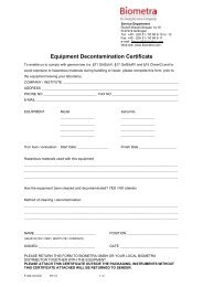
Functional and Operating Elements8. Functional and Operating Elements8.1 Temperature control module <strong>KH</strong>-5frontrear302711121415281629467251383A1A Symbol: Read the instruction manual!1 Mains switch2 Reset button3 Menu selection key4 Heating control display5 Menu position display6 Set or actual temperature display7 Value alteration () higher () lower8 Enter key11 Mains connection12 Fuses (if this fuse is triggered, see chap. 12.4)13 Excess temperature setting dial14 outlet to application15 inlet from application16 fan27 Switch for cooling on/off28 Filling level29 Draining port30 Display and user interface13<strong>Manual</strong>_<strong>KH</strong>-5_Ver00
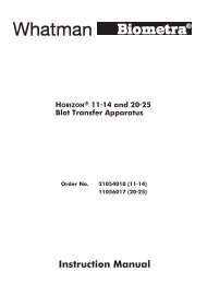
Connecting Hoses9. Connecting Hoses4leftoutinrightAPump nozzle A:left: outlet to external object (pressure side)right: return flow from external objectHoses are normally used to connect the pump with an externalvessel.General recommendations concerning the max. allowablelength of hoses cannot be given. It all depends largely on thesize, form and material of the external vessel to be temperaturecontrolled. It should be understood that the length of a hose andits diameter combined with the circulating capacity have a largeeffect on the temperature control effectiveness. Wheneverpossible, the decision should be made in favor of the widerhose diameter and the vessel to be temperature controlledshould be placed as close as possible to the circulator.!!!!!High operating temperatures will lead to hightemperatures on the hose surface, this is even moreso at the metal nozzles. In this case: DO NOT TOUCH!The required hose material is dependent on the heattransfer liquid used.Hoses must not be folded or bent!A wide radius should be used if turns have to bemade!Hoses may become brittle after prolonged use or theymay get very soft. They should, therefore, be checkedregularly and exchanged if necessary!Secure all hose connections using hose clamps!14<strong>Manual</strong>_<strong>KH</strong>-5_Ver00
Connecting Hoses9.1 Plastic hosesIt must be ensured that the hoses selected are fully suitable forthe particular application, i.e. that they will not split, crack orbecome disengaged from their nozzles.Perbunan hoses have proved to be satisfactory for yourcirculator.These hoses are available as running meter goods with internaldiameters of 8 or 12 mm.Hoses made of other materials are also available from ThermoScientific.Hoses with 12 mm internal diameter can be pushed directlyonto the nozzle A.9.2 Connection of external closed systemsE.g. instruments with a pressure–tight temperature jacket or coilor a heat exchanger.EZ COOL 80Hose connection:From the pressure port (at the left) to the external object andthen back to the return port (at the right).AIf it cannot be avoided that the external object is situated higherthan the circulator, the heat transfer will only not flow back onthe condition that the system is completely tight and leak–free.To be on the safe side it may be considered necessary to fitstop cocks to the inlet and outlet hoses.ExternalObject15<strong>Manual</strong>_<strong>KH</strong>-5_Ver00
Filling10. Filling with Bath Liquid 410.1 Recommended bath liquids5 to 80C Distilled Water• Normal tap water leads to calcareous depositsnecessitating frequent unit decalcification.Calcium tends to deposit itself on the heating!element. The heating capacity is reduced and servicelife shortened!• Water, of course, can be employed up to 95C, howeverabove 80C water vaporization reaches a level whichnecessitates the liquid to be constantly replenished.Add an appropriate amount of Chloramine T to avoidalgae growth in the water.- 10 to 80C Water with AntifreezeIn applications below 5C the water has to be mixed with anantifreeze. In doing so, the amount of antifreeze added shouldcover a temperature range 5C lower (but max. -30C) thanthe operating temperature of the particular application. This willprevent the water from gelling (freezing) in the area of theevaporating coil the surface area of which is much colder thanthe working temperature. An excess of antifreeze deterioratesthe temperature accuracy due to its high viscosity.! Important !Biometra takes no responsibility for damages caused bythe selection of an unsuitable bath liquid.16<strong>Manual</strong>_<strong>KH</strong>-5_Ver00
Filling10.2 Filling with heat transfer liquidWhen working with water or water with antifreeze:Fill the internal tank with about 3.6 liter of heat transfer fluid.Use the filling port at the top left corner of the unit. Adjustcarefully to the max level and check the level regularly. If levelis below minimum you need to refill. Below the min. level thecooling capacity is decreased significantly.External systems included within the circulating circuit have tobe filled with the same heat transfer liquid in order to avoid toomuch liquid being drawn from the internal bath.The bath level should be checked when the presettemperature has been reached!Quite often closed external systems cannot be prefilled assuggested. In this case the internal bath of the unit has to befilled to the max. level. After starting the unit, the pump will feedthe necessary liquid to the external system. Should the demandbe higher than the volume difference between high and low, thelow liquid level sensor will be activated and the pump switchedoff.In this case:21 Replenish the liquid,2 Reset the unit:Depress the key 2 (at the front).⇒The unit starts up again3 Repeat this action if necessary.17<strong>Manual</strong>_<strong>KH</strong>-5_Ver00
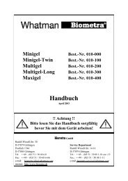
Draining11. DrainingThe temp. control unit is drained at the nozzle 23.231 Place a suitable vessel underneath nozzle.Bear in mind that the liquid will run out in a slight arc.2 Turn plug slowly until it becomes disengaged from thethread. A pin will prevent the liquid from running out rightaway.3 Pull out plug (pin) in one quick motion. The liquid will startto run out.4 Possible residues can be drained by tilting the circulatorslightly.!Hot heat transfer liquid should not be drained! Whencertain conditions make draining necessary, pleaseact safety conscious: Wear protective clothing andprotective gloves!18<strong>Manual</strong>_<strong>KH</strong>-5_Ver00
Excess Temperature Protection230 V115 V12. Connecting Up12.1 Connecting to the mainsOnly attach this unit to mains sockets with a grounded earth.Compare the local mains voltage with the specifications writtenon the name plate. Voltage deviations of +/– 10% arepermissible. The socket must be rated as suitable for the totalpower consumption of the unit.12.2 Checking the liquid circuitBefore switching on, check again to make sure that thepressure and suction ports are connected with each other - oralternatively if an external object is to be temperaturecontrolled, that the hoses are connected correctly and secured(see chapter 9.2).12.3 Changing the mains plug (e.g. for Great Britain)!This should only be carried out by qualified specialistpersonnel!The mains cable wires have the following colors:Brown = LiveBlue = NeutralGreen/Yellow =Earth12.4 Fuses on the unitAll units are equipped with automatic thermally–triggered fuses.If the fuse 12 has triggered• the fuse does not have to be exchanged - resettingsuffices;• a white marking is visible;12• a certain cooling down time should be allowed (approx. 5min) before the (dip) switch can be pressed again.!Do not use tools; do not use force. Both destroy thefuse.!If the fuse should be triggered again after resetting,the unit probably has a defect. In this case the unitshould be sent in for servicing.19<strong>Manual</strong>_<strong>KH</strong>-5_Ver00
Excess Temperature Protection13. Operating45613.1 Switching on1 Set the excess temperature protection clearly above thedesired operating temperature using the dial 13.2 Switch the circulator on at the mains switch 1.131⇒This causes:Display 6 briefly shows the device identification andthereafter the version number of the operating systemsoftware, e.g. ”0.11”, and after that the actualtemperature at the location of the control sensor isdisplayed.⇒The display 5 shows which one of the four adjustable setvalues is currently activated (set temperature ”S” or oneof the fixed temperatures ” F1”, ” F2” ,” F2” (see chapter13.4).⇒The pump motor runs - the bath liquid is circulated.27The cooling device is switched on via it’s own switch for cooling27 at the front. The compressor starts with a slight jerk. Onlyactivate cooling device if cooling is actually required.13.2 Heating control lampThe display 4 lights up when the heating is switched on (settemperature is higher than the actual temperature).⇒⇒display 4 lights up constantly during the heating up phase,display 4 flashes on and off during the control phase.The display 4 does not light up if the heating is not activated(set temperature is lower than the actual temperature).20<strong>Manual</strong>_<strong>KH</strong>-5_Ver00
Excess Temperature Protection13.3 Adjusting the variable set temperature1 Press the menu button 3:75683⇒ A left–justified ”S” appears in the small display 5(for set temperature adjustment).2 Increase ( ↑ ) or decrease ( ↓ ) the value shown in thedisplay 6 with the buttons 7 . The first degree oftemperature change is thereby passed slowly andthereafter the rate of temperature change in the display isfive times faster.3 Press the enter button 8.⇒ The selected value is stored as new set temperature andactivated.The new value is not saved until the Enter button hasbeen pressed. The circulator continues to use the old setvalue.The display 6 automatically switches back to actual temperaturedisplay after a short time.13.4 Adjusting the fixed temperatures F1 to F3(facultative)This device permits permanent storage of three fixedtemperatures which can be activated when required.1 Press the menu button 3 :⇒ The small display 5 shows F1 (for fixed temperature 1 ),F2 or F3 .2 Press the buttons 7 to increase ( ↑ ) or decrease ( ↓ ) thevalue shown in the display 6 .3 Press the enter button 8 .⇒ The selected value is stored as fixed temperature F1, F2or F3 and activated as currently valid set value.The display 6 automatically switches back to actual temperaturedisplay after a short time. At the same time the small display 5shows whether the temperature set point S, F1, F2 or F3 iscurrently active.To activate another set value, press the menu button 3 until thedesignator of the desired set point (e.g. ”S” ) is shown in thedisplay 5. Then press the button 8 to confirm without changingthe value.21<strong>Manual</strong>_<strong>KH</strong>-5_Ver00
Excess Temperature Protection14. Excess Temperature Protection72136If one of the safety devices is triggered:• The fault cause is shown in the display 6(see also chapter 16.).• all voltage conducting unit components (the heatingelement and pump motor) are switched off immediatelyi.e. the safety circuit transfers the unit to a stable, safecondition.The fault cause must be identified and remedied.After the fault has been eliminated the unit can be started againby pressing the Reset key 2.14.1 Excess temperature protection dialIt offers protection against dangers caused by an uncontrolledheating up of the heat transfer liquid above the desired settemperature.The cut–off temperature is adjusted with the excesstemperature setting dial 13.13Proper protection can only be guaranteed if thecut–off point has been correctly set.There are two main aims for correct setting:• Safety (primary importance):Protection against ignition of the heat transfer liquid.The cut–off point must be set at least 25° C below the firepoint of the bath liquid used. However, this unit is for usewith water only.• Protection of the object to be temperature controlled(secondary importance):Additional protection, e.g. of a biological sample. The cut–off point should be set as close as possible to the desiredtemperature value.22<strong>Manual</strong>_<strong>KH</strong>-5_Ver00
Excess Temperature Protection1314.1.1 Setting the excess temperatureThe cut–off point is set with the excess temperature dial 13 witha rough scale of temperature values arranged around it. Thisscale, of course, can only serve as an approximate settingmeans for this cut–off point. However, the cut–off point can bedetermined to act exactly if the following procedure is adheredto:If for instance a bath liquid has a fire point of 60C the unitshould cut off after reaching 35C at the latest:1 First set the desired set value “S” using keys 7 (↑) or (↓)to exactly 35° C.2 After the circulator has reached this temperature, turn theexcess temperature dial 13 backwards very slowly (to theleft) until the unit cuts off (fault message on display 6).3 Reset the unit via the Reset key 2 after the heat transferliquid has cooled down somewhat.4 Then set the set temperature to the actual temperature(< 35° C).⇒The unit can now be used for temperatures below35° C. As soon as 35° C is reached, it is securelyswitched off.14.1.2 Testing the cut–off pointSet the set temperature to a higher value than 35° C, set theunit to heat up and watch the digital display or thermometer.The value indicated when the alarm goes off is the real cut–offtemperature. The reaching of the cut–off point is indicated atthe display by the following message:23<strong>Manual</strong>_<strong>KH</strong>-5_Ver00
Configuration7568315. ConfigurationThe device is completely ready for operation after defining thedesired set temperature and adjusting the overtemperatureprotection. It is furthermore possible to adjust or call–up severalfunctions in the function mode ”FU”.FUENDQuit configurationmodeSOLL RTA CON H-LAdjust setvalues S andF1 to F3Adjust correc–tion factors cSand c1 to c3Version no.,temperatureresolution, etc.High and lowtemperaturelimits1 Switch to function mode by pressing the menu button 3several times (until display 5 shows FU).2 Switch to the desired function SOLL, RTA, CON or H-Lwith the arrow buttons 7. Press the enter button 8 toconfirm the selection made.3 Move around through the submenus with the menu button3 (see chapter ”Menu Tree”).4 A further press of the menu button 3 quits function modeand returns to display of the actual temperature.Display 6 always returns automatically to actualtemperature display after a short time.END is provided to skip function mode without makingany settings.15.1 Set value S and fixed temperatures F1 to F3The adjustment has already been made in chap. 13.3 and 13.4.In the function mode it is also possible to adjust and changethese set values without activating them.1 Press the arrow buttons 7 in the menu FU to change tothe SOLL function. Press the enter button 8 to confirmthis selection.2 Press the menu button 3 to move through the submenusS, F1 to F3 (the procedure for making adjustments is thesame as in chapter 13.3).A correcting factor c should be associated with each value:S ⇔ cS, F1 ⇔ c1 ... (see chapter 15.2).24<strong>Manual</strong>_<strong>KH</strong>-5_Ver00
Configuration15.2 Adjusting the correction factors (RTA system)Display 6 shows the actual temperature at the control sensor.This temperature does not correspond directly to thetemperature in the circulator’s bath and even less to thetemperature in the external connected system.The temperature difference is determined by measuring theactual current temperature using a suitable measuring device(calibrated or gauged thermometer).This is how the correction factor c (RTA system) is enteredinto the circulator. It remains stored in the circulator and isautomatically assigned to the corresponding set temperature.The same as for the set values in chap. 13.4, four correctionfactors can be stored: cS , c1 , c2 and c3 , whereby, forexample, c1 is the correction value associated with F1.The resolution of the correction factor according to the RTAsystem is 0.01 °C and the possible range of variation is ±9.9 °C.Entry (see also the example on the next page):1 Switch to the RTA function with the arrow buttons 7 inthe menu FU. Press the enter button 8 to confirm thisselection.2 Press the menu button 3:⇒ The small display 5 shows cS (correction factor forworking with the set temperature S ).3 Set the determined temperature difference on the display6 with the buttons 7.4 Press the enter button 8.⇒This confirms the value as new correction factor cS.Proceed analogously as described for cS to adjust thecorrection factors c1 to c3 for the set values F1 to F3.The new value is not saved until the Enter button hasbeen pressed. The circulator continues to use the oldvalue.Warning: The correction factor ”c” may have to bedetermined again if the set temperature is altered!25<strong>Manual</strong>_<strong>KH</strong>-5_Ver00
ConfigurationThe display 6 automatically switches back to actual temperaturedisplay after a short time.After the Enter button 8 has been depressed, the correctionvalue “c” (like the set value) remains stored even in case of apower failure.26<strong>Manual</strong>_<strong>KH</strong>-5_Ver00
ConfigurationExample:Set value programmed at the circulator T set = 70.7° CActual temperature in bath / system T act = 70.5° C⇒ Deviation, calculated according toT = T set - T act∆T = 0.2° C⇒∆ Entry of the corrected value T ascorrection factor “ ” = +0.2° CThe temperature control is thus internally altered so that thedesired 70.7C is also attained in the external system. Thetemperature displayed at the circulator and that of the externalsystem now correspond with each other.27<strong>Manual</strong>_<strong>KH</strong>-5_Ver00
Configuration15.3 Displaying the version of the operating softwareIt is often necessary to know the version number of the softwarefor service and other manufacturer inquiries.1 Change to con in the menu FU and press button 8 toconfirm. Press button 3 to switch to BS . The versionnumber appears in the upper display 6 .15.4 Secured mode1 Change to con in the menu FU and press button 8 toconfirm. Press button 3 to switch to 88 .2 Switch security mode ON or OFF with the arrow buttons7 and press button 8 to confirm.Secured mode: ONThe temperature control module switches to the secured modein case of a power failure or if it is switched on via the mainsswitch. Display 6 flashes over all segments 8888.Switching on again is only possible after the reset button 2 hasbeen pressed. This is due to safety reasons.The unit reacts in the same way if is switched on via a mainsswitch in the laboratory.Secured mode: OFFAfter a power failure or if it is switched on via the mains switchthe temperature control module will switch on and start heatingcorresponding to the stored values and the last temperatureused.!Please consider any possible resulting risks!15.5 Adjusting the LED display contrast1 Change to con in the menu FU and press button 8 toconfirm. Switch to In with button 3.2 Press the arrow buttons 7 to change the display contrast(0 to 15) and then press button 8 to confirm the setting.15.6 Resolution of the temperature display1 Change to con in the menu FU and press button 8 toconfirm. Switch to tA with button 3 .2 Choose the resolution (0.1 or 0.01° C) with the buttons 7and then press the button 8 to confirm (0.01° Cresolution is available only in the display range from -9.5to +99.5° C).28<strong>Manual</strong>_<strong>KH</strong>-5_Ver00
Configuration15.7 Adjusting temperature limit valuesThe setting range of the operating temperature of the circulatorcan be limited if the application requires this.!This is not a safety element but merely an aid to helpavoid user faults when operating the unit. The excesstemperature protection must be set separately.1 Change to the function H-L with the arrow buttons 7 inthe menu FU. Then press the enter button 8 to confirmthe selection.2 Press the menu button 3 :⇒ The small display 5 shows LL (Low Limit temperaturevalue).3 Set the desired limit value with the arrow buttons 7 (thelowest possible temperature is -30° C).4 Press the enter button 8 .⇒ The chosen value is stored as low limit value LL .To set the high limit value HL, proceed analogously asdescribed for LL.HL (High Limit): The highest possible temperature is 100° C.The new value is not saved until the Enter key hasbeen pressed. The circulator continues to use the oldvalue.5 Press the menu button 3 again to quit function mode andreturn to display of the actual temperature.Or just wait until the displays 5 and 6 automaticallyreturn to actual temperature display mode after a shortdelay.29<strong>Manual</strong>_<strong>KH</strong>-5_Ver00
Fault Displays25616. Fault DisplaysDisplay 6 shows the fault message ” XXXX ”.” ” is shown on display 5.The heating element and pump are completely switchedoff.The following faults are possible:= Excess temperature= Pump or motor overloading= Sensor breakage or short circuit= Undefined fault16.1 Excess temperatureThe low liquid level protection can be triggered if:• Excess temperature has been set too closely tothe desired working temperature⇒ increase value slightly according tospecifications made in chapter 14.1.1.• the control function is defective⇒ Return unit for servicing.16.2 Pump or motor overloadingThe motor or pump is blocked:⇒It can take 10 min or longer, until the motortemperature has sunk far enough so that the unitcan be switched on again by pressing the resetkey 2. If the circulator switches off again after ashort time, return the unit for servicing!30<strong>Manual</strong>_<strong>KH</strong>-5_Ver00
Fault Displays16.3 Sensor breakage or short circuitThe sensor must be exchanged by qualified servicepersonnel. Please return unit for repairs.16.4 Undefined faultThis can be caused by fault which only occurs for a shortperiod of time, i.e. with a fluctuating bath level when thefilling level is very close to minimum.Before returning the unit, top up with heat transfer liquid.This fault can often be remedied in this way!In all other cases this unit must be checked by qualifiedservice personnel.16.5 Fault eliminated?After the fault has been eliminated, the cause of the faultis shown on the display 6 (e.g. ). The precedingthree zeros mean that the fault has been eliminatedThe reset key 2 must be pressed in order to start up theunit again.31<strong>Manual</strong>_<strong>KH</strong>-5_Ver00
Testing the Safety Features17. Testing the Safety FeaturesThe safety feature for excess temperature protection must bechecked at regular intervals. The level of regularity of checkingdepends on the unit’s designated application and the heattransfer liquid used (inflammable or non–inflammable). Practicalexperience has shown that between 6 to 12 times a year issufficient.17.1 Excess temperature protectionSet a cut–off temperature (see chapter 14.1) that is lower thanthe desired set temperature. Switch on the circulator and checkif the circulator really does switch itself off at the set cut–offtemperatureIf not follow the specifications detailed in chapter 14.1.1.It may be deemed necessary to have the unit checked over byqualified service personnel.32<strong>Manual</strong>_<strong>KH</strong>-5_Ver00
Cooling18. Cooling27The refrigerated bath is used mainly for enabling lower thanambient or tap water temperatures in circulators or for coolinga heated bath down to a low temperature level very quickly.The working temperature range is shown in the technicalspecifications.1 In this case switch the refrigerated bath off at the mainsswitch 27.Switching the cooling compressor on for quick cooling downpurposes (even at working temperatures of 80° C) is howeverpermissible.33<strong>Manual</strong>_<strong>KH</strong>-5_Ver00
Maintenance19. MaintenanceThe stainless steel surfaces of the bath vessel and of thehousing may after some time show spots and becometarnished. Normal stainless steel cleaners as they are used inthe kitchen can be used. The bath vessel and built–incomponents should occasionally (at least every time the bathliquid is changed) be cleaned using a household cleaner.Vinegar–based cleaners have proved to be suitable usedaccording to the manufacturers recommendations.Do not use scouring powder!Use only distelled water as temperature fluid to avoidcalsium spots. Also to make up water / glycolmixtures.The inside of the bath vessel must be kept clean in order toensure a long service life. Substances containing acidic oralkaline substances and metal shavings should be removedquickly as they could harm the surfaces causing corrosion. Ifcorrosion (e.g. small rust marks) should occur in spite of this,cleaning with stainless steel caustic agents has proved to besuitable. These substances should be applied according to themanufacturers recommendations.19.1 Cleaning the fins of the liquefierIn order to maintain the cooling capacity of the unit, cleaninghas to be done two to four times per year, depending on thegrade of soiling.!Switch off the unit and pull out the mains plug.19.2 Discarding the unit:One day the life span of your cooling unit will end.Therefore:!This unit contains ozone–friendly coolant R134a.The unit may however only be discarded byauthorized personnel.34<strong>Manual</strong>_<strong>KH</strong>-5_Ver00
Technical Specifications and Service20. Technical specifications20.1 Technical specifications of the temperaturecontrol moduleOperating temperature *) ° C -10..80Temperature accuracy ± K 0.1Heater capacity 230V / 115V W 1500 / 1100Pump pressure max. mbar 250Max. flow rate during circulation using12 mm ø hosesl/min 12Voltage V 230 ±10% or 115 ±10%Frequency 230V / 115V Hz 50..60 / 60Total wattage consumption 230V /115VSafety elements according tocategoryExcess temp. protectionMotor overload protectionFIS–systemTemperature settingSetting limitationTemperature displayRTA–systemControl typeControl sensorVA 2050 / 1250NFLvariableyesyesdigitalyesLED greenyesPIDdigital IC* The working temperature range is dependant on the cooling selected.The product is compliant with EN 61000-3-11 requirements and underlies special connection conditions. The maximal electricimpedance must not exceed (0.083+ j 0.052) Ohm.35<strong>Manual</strong>_<strong>KH</strong>-5_Ver00
Technical Specifications and Service21. ServiceShould you have any problems with this unit, please contact our service department or your localBiometra dealer:Biometra biomedizinische Analytik GmbHService DepartmentRudolf-Wissell-Straße 14 - 16D-37079 GöttingenGermanyTel. +49 551-50881 – 10 or -12Fax +49 551-50881 – 11e-mail: service@biometra.deAttention:If you would like to send the unit back to us, please read the following instructions.Instructions for return shipment• Return only defective devices. Please contact the Technical Service Department at Biometra(Tel. +49 551-50881 – 10 or -12) to get an Return Authorization Number (RAN number).• Use the original box or a similarly sturdy one.• Label the outside of the box with “CAUTION! SENSITIVE INSTRUMENT!” and the RAN numbersticker. Deliveries without RAN number cannot be accepted!• Please enclose a precise description of the fault, which also reveals during which proceduresthe fault occurred, if possible.Important:Clean all parts of the instrument from residues, and of biologically dangerous,chemical and radioactive contaminants. Please include a written confirmation thatthe device is free of biologically dangerous and radioactive contaminants in eachshipment. If the device is contaminated, it is possible that Biometra will be forced torefuse to accept the device.• The sender of the repair order will be held liable for possible losses resulting frominsufficient decontamination of the device.• Please enclose a note which contains the following:a) Sender’s name and address,b) Name of a contact person for further inquiries with telephone number.36<strong>Manual</strong>_<strong>KH</strong>-5_Ver00
Technical Specifications and Service22. Equipment Decontamination CertificateTo enable us to comply with German law (i.e. §§28 and 80 StrlSchV, §17 GefStoffV and §19 ChemG) and toavoid exposure to hazardous materials during handling or repair, will you please complete this form, prior tothe equipment leaving your laboratoryCOMPANY / INSTITUTE _________________________________________________________ADDRESS_________________________________________________________PHONE NO _________________________ FAX NO__________________________E-MAIL _______________________________________________________________________EQUIPMENT Model Serial No________________________________________________________________________________________________________________If on loan / evaluation Start Date: __________________ Finish Date __________________Hazardous materials used with this equipment_____________________________________________________________________________________________________________________________________________________________________________________________________________________________________________Method of cleaning / decontamination_____________________________________________________________________________________________________________________________________________________________________________________________________________________________________________The equipment has been cleaned and decontaminated:NAME ___________________________________(HEAD OF DIV./ DEP./ INSTITUTE / COMPANY)SIGNED __________________________________POSITION _________________________DATE _____________________________PLEASE RETURN THIS FORM TO BIOMETRA GMBH OR YOUR LOCAL BIOMETRA DISTRIBUTORTOGETHER WITH THE EQUIPMENT.PLEASE ATTACH THIS CERTIFICATE OUTSIDE THE PACKAGING. INSTRUMENTS WITHOUT THISCERTIFICATE ATTACHED WILL BE RETURNED TO SENDER.37<strong>Manual</strong>_<strong>KH</strong>-5_Ver00
Technical Specifications and Service23. Note for Disposal of Electric/ElectronicWasteThis symbol (the crossed-out wheelie bin) means,that this product should be brought to the returnsystems and/or separate systems available to endusersaccording to yours country regulations, whenthis product has reached the end of its lifetime!For details, please contact your local distributor!This symbol applies only to the countries within the EEA*.*EEA = European Economics Area, comprising all EUmembersplus Norway, Iceland and Liechtenstein.38<strong>Manual</strong>_<strong>KH</strong>-5_Ver00
Technical Specifications and Service23. EC – Declaration of ConformityEU - KonformitätserklärungMarch 2008im Sinne der EG-Richtlinie über elektrische Betriebsmittel zur Verwendung innerhalb bestimmterSpannungsgrenzen 2006/95/EGfollowing the EC directive about electrical equipment for use within certain limits of voltage2006/95/ECund / andim Sinne der EG-Richtlinie für die elektromagnetische Verträglichkeit 2004/108/EGfollowing the EC directive about the electromagnetic compatibility 2004/108/ECund / andim Sinne der EG-Richtlinie für Druckgeräte 97/23/EG.following the EC directive about pressure equipment 97/23/EC.Hiermit erklären wir, dass folgender Kühlthermostat,Herewith we declare that the following Refrigarating <strong>Circulator</strong>,Typ / type:<strong>KH</strong>-5Best.-Nr. / Order No. 043-400 (230 V), 043-490 (115 V)den grundlegenden Anforderungen dercorresponds to the basic requirements ofEG-Niederspannungsrichtlinie 2006/95/EG und derEC low voltage directive 2006/95/EC EC and theEG-Richtlinie über die elektromagnetische Verträglichkeit 2004/108/EG und derEC directive about the electromagnetic compatibility 2004/108/EC and theEG-Richtlinie für Druckgeräte 97/23/EG entsprechen.EC directive for pressure equipment 97/23/EC.Dr. Juergen OtteQuality Manager39<strong>Manual</strong>_<strong>KH</strong>-5_Ver00
Technical Specifications and Service24. WarrantyThis laboratory instrument is produced with the highest practical standards of materials,workmanship, and design. The design and manufacture of parts have been conceived with onepurpose - to produce units which will give satisfactory service.Biometra GmbH guarantees this unit to be free from defects in materials or workmanship undernormal use or service for 24 month from date of shipment.If, during this time, this unit proves defective in materials or workmanship, Biometra GmbH willrepair or replace it free of charge if returned to us prepaid.This guarantee does not cover damage in transit, damage caused by carelessness, misuse orneglect, or unsatisfactory performance as a result of conditions beyond our control; orconsequential losses as a result of failure of our product.Biometra biomedizinische Analytik GmbHService DepartmentRudolf-Wissell-Str. 30 Rudolf-Wissell-Str. 14-16D-37079 Göttingen D-37079 GöttingenGermanyGermanyTel. +49 551-50686-0 Tel. +49 551-50881-10 or -12Fax +49 551-50686-66 Fax. +49 551-50881-11e-mail: info@biometra.dee-mail: service@biometra.deinternet: http://www.biometra.de40<strong>Manual</strong>_<strong>KH</strong>-5_Ver00