MAIN 24 Fi – 24 i SPARE PARTS CATALOGUE - AIRCO line
MAIN 24 Fi – 24 i SPARE PARTS CATALOGUE - AIRCO line
MAIN 24 Fi – 24 i SPARE PARTS CATALOGUE - AIRCO line
- No tags were found...

Create successful ePaper yourself
Turn your PDF publications into a flip-book with our unique Google optimized e-Paper software.
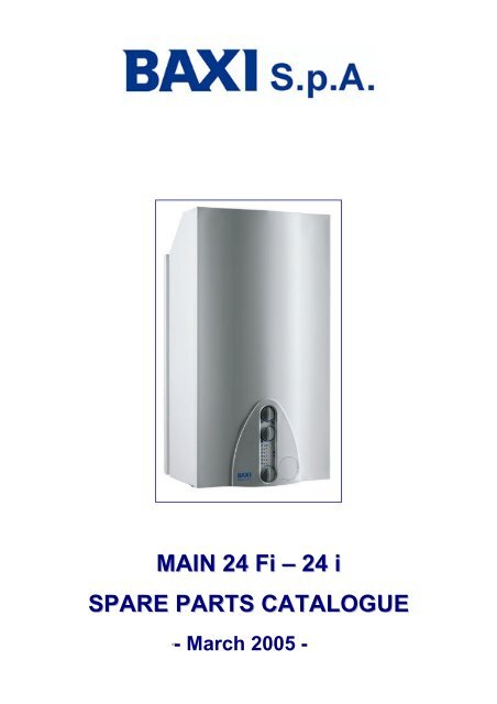
<strong>MAIN</strong> <strong>24</strong> <strong>Fi</strong> <strong>–</strong> <strong>24</strong> i<strong>SPARE</strong> <strong>PARTS</strong> <strong>CATALOGUE</strong>-
COME SI CONSULTA IL CATALOGO RICAMBIDopo le tavole esplosi caldaie si trovano le liste dei componenti delle caldaie, suddivise in varie colonne, con ilseguente significato:Pos.DescrizioneCodeTab. XXFrom serialnumberTo serialnumberInterchangeableNumero di identificazione del componente nella tavola esploso della caldaia.Breve descrizione del componente.Codice BAXI S.p.A. del componente.XX è il numero della tavola esploso caldaia riferita al modello in esame.Data (anno e settimana) di inizio produzione di un componente (prime quattro cifre della targamatricola caldaia).Esempio: B005: anno 2000 (B indica il decennio 2000-2009; 0 indica l’anno) - 5^ settimana.Se la casella è vuota significa che il componente è in uso dall’inizio produzione del modello dicaldaia.Data (anno e settimana) di fine produzione di un componente (prime quattro cifre della targamatricola caldaia).Esempio: B012: anno 2000 <strong>–</strong> 12^ settimana (N.B. la data di fine produzione è da considerarsiindicativa). Se la casella è vuota significa che il componente è ancora in uso.Intercambiabilità tra nuovo componente entrato in produzione e vecchio componente uscitodalla produzione.YES: il nuovo componente è intercambiabile con quello vecchio.NO: il nuovo componente non è intercambiabile con quello vecchio.HOW TO READ THE <strong>SPARE</strong> <strong>PARTS</strong> <strong>CATALOGUE</strong>In the spare part catalogue, after the exploded diagrams, there are the components lists of the boilers; this is themeaning of the different columns:Pos.DescriptionCodeTab. XXFrom serialnumberTo serialnumberInterchangeableIdentification number of the component in the exploded diagram of the boiler.Short description of the component.BAXI S.p.A. code of the component.XX is the exploded diagram number of the boiler taken into consideration.Date (year and week) identifying the beginning of production of a component (taken from theserial number of the boiler).e.g. B005: year 2000 (B identifies the decade 2000-2009; 0 identifies the year) <strong>–</strong> 5 th week.If the box is empty, the component is in use from the beginning of production of the boiler.Date (year and week) identifying the end of production of a component (taken from the serialnumber of the boiler).e.g. B012: year 2000 (B identifies the decade 2000-2009; 0 identifies the year) <strong>–</strong> 12 th week.If the box is empty, the component is still in use.It identifies the interchangeability between the new component and the old one.YES: components are interchangeable.NO: components are not interchangeable.
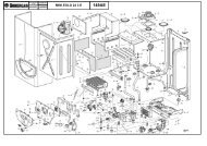
<strong>MAIN</strong> <strong>24</strong> <strong>Fi</strong> - iPos Description Code1/3/05Tab.01BSB436<strong>24</strong>X650-<strong>MAIN</strong> <strong>24</strong> FITab.01BSB432<strong>24</strong>X650-<strong>MAIN</strong> <strong>24</strong> iBSB436<strong>24</strong>X651-<strong>MAIN</strong> <strong>24</strong> FITab.02Tab.02BSB432<strong>24</strong>X651-<strong>MAIN</strong> <strong>24</strong> iX=1->LPG / X=3->NATURAL GASFrom serialnumberTo serialnumberInterchangeableNote2 LEFT PANEL ASSEMBLY 5663680 • •2 LEFT PANEL ASSEMBLY 5668310 • •3 RIGH PANEL ASSEMBLY 5663670 • •3 RIGH PANEL ASSEMBLY 5668300 • •4 FRONTAL PANEL 5113850 • • • •5 FRONTAL TRAVERSE 5113790 • • • •8 AIR PRESSURE SWITCH PIPE L=270 5408080 • •9 SUCTION RESTRICTOR D.80 5108700 • •10 COAXIAL FLUE GASKET 5409450 • •12 SUCTION CAP 5108690 • •13 SUCTION CAP GASKET 5407400 • •15 JOINT ASSEMBLY D. 100 L=20 (with screws) 5664050 • •18 FLUE PLASTIC VENTURI 5409580 • •21 GASKET 6,1X12X1,5 WRC 5402050 • • • •22 FAN 1 SPEED 5663810 • •23 FAN PRESSURE SWITCH 5663820 • •<strong>24</strong> COMPENSATION PIPE L=130 5407930 • •25 CONVEYOR 5113800 • •25 CONVEYOR ASSEMBLY 5668420 • •27 COMBUSTION CHAMBER ASSEMBLY 5663650 • •27 COMBUSTION CHAMBER ASSEMBLY 5668290 • •28 LATERAL INSULATING PANEL 5212210 • • YES28 LATERAL INSULATING PANEL 5213210 • •28 LATERAL INSULATING PANEL 5212510 • • YES28 LATERAL INSULATING PANEL 5213220 • •29 REAR INSULATING PANEL 5212220 • • • • YES29 REAR INSULATING PANEL 5213280 • • • •30 FRONTAL INSULATING PANEL (FF) 5212260 • • YES30 FRONTAL INSULATING PANEL (FF) 5213370 • •30 FRONTAL INSULATING PANEL (FF) 5212540 • • YES30 FRONTAL INSULATING PANEL (FF) 5213380 • •31 COMB. CHAMBER PANEL 5113820 • •31 COMB. CHAMBER PANEL 5114290 • •32 BI-THERMAL HEAT EXCHANGER 5663720 • • • •32 BI-THERMAL HEAT EXCHANGER + OR (5663720 + 5404600) 616170 • • • •33 O-RING 22X3 EPDM 5403130 • • • •34 PRIMARY EXCHANGER CLIPS 5113650 • • • •35 EXPANSION VESSEL 8L 5663880 • •35 EXPANSION VESSEL 7L 5668370 • •37 SEALED CHAMBER FRONT PANEL 5663830 • •38 PILOT SIGHT GLASS GASKET 5401610 • •39 PILOT SIGHT GLASS 5203930 • •40 PILOT SIGHT FRAME 5103360 • •41 BURNER ASSEMBLY (13 ELEMENTS) 5663710 • • • •43 GAS RAMP WITH INJECTORS (N.G. D.1,28) 612960 • •43 GAS RAMP WITH INJECTORS (N.G. D.1,18) 615260 • •44 L.P.G. INJECTORS KIT D=0,74 5666390 • • • •44 NATURAL GAS INJECTORS KIT 5666400 • •44 NATURAL GAS INJECTORS KIT 5669460 • •45 GAS RAMP GASKET 5407940 • • • •46 GAS RAMP CONNECTING FLANGE 5211030 • • • •47 GASKET (GAS RAMP/SEALED CHAMBER) 5404760 • •49 HOSE ADAPTER CAP 5409520 • •59 IGNITION ELECTRODE CABLE 8419050 • • • •61 ELECTRODE PROTECTION CAP 5407830 • • • •62 SEALED CHAMBER HOSE ADAPTER 5409570 • •63 IGNITION ELECTRODE 8422570 • • • •70 PIPE ASSEMBLY (PUMP/EXCHANGER) 5663730 • •70 PIPE ASSEMBLY (PUMP/EXCHANGER) 5668320 • •72 PUMP UP 15-50 AO (GRUNDFOS) 5655200 • • • •73 AIR VENT VALVE WITH O-RING (CALEFFI) 607290 • • • •74 OR 14X1,78 EP 5406360 • • • •80 HYDRAULIC INLET GROUP 5212<strong>24</strong>0 • • • •90 FILLING TAP 5663780 • B32390 FILLING TAP 5667980 • • • • B323 NO91 DRAINING TAP 5652030 • • • •92 HYDRAULIC SAFETY VALVE WITH O.R. -3 bar- 5653690 • • • •115 BY-PASS PLUG ASSEMBLY 5663020 • • • •131 NTC SENSOR (HONEYWELL) 8434820 • • • •132 NTC SENSOR GASKET 5402830 • • • •135 LIMIT THERMOSTAT 105°C 9950760 • • • •137 GAS PIPE 5663690 • 1137 GAS PIPE 5669650 • 2137 GAS PIPE 5668360 • 3
<strong>MAIN</strong> <strong>24</strong> <strong>Fi</strong> - iPos Description Code1/3/05Tab.01BSB436<strong>24</strong>X650-<strong>MAIN</strong> <strong>24</strong> FITab.01BSB432<strong>24</strong>X650-<strong>MAIN</strong> <strong>24</strong> iBSB436<strong>24</strong>X651-<strong>MAIN</strong> <strong>24</strong> FITab.02Tab.02BSB432<strong>24</strong>X651-<strong>MAIN</strong> <strong>24</strong> iX=1->LPG / X=3->NATURAL GASFrom serialnumberTo serialnumberInterchangeableNote137 GAS PIPE 5670420 • 4138 O-RING 22,22X2,62 5402010 • •140 GAS VALVE (SIT 845063 SIGMA) 5658830 • • • •140 GAS VALVE (HONEYWELL VK4105M 5033) 5665220 • • 5147 CONNECTION TRAVERSE 5113780 • •147 CONNECTION TRAVERSE 5668500 • • • •151 ELECTRIC BOX REAR COVER 5409550 • • • •152 PRINTED CONTROL PANEL 5663890 • •152 PRINTED CONTROL PANEL 5668390 • •154 P.C.B. (SIT) 5663840 • B323154 P.C.B. (SIT) 5668020 • • • • B323 YES154 P.C.B. (HONEYWELL) 5669660 • • • • B406 YES162 PANEL PLATE 5665020 • •162 PANEL PLATE 5668410 • •166 TERMINAL BLOCK 8421590 • • • •167 FUSE HOLDER 5405340 • • • •168 FUSE (2A-250V) 9950580 • • • •169 MANOMETER D.40 -T&G 9951330 • • • •174 KNOB 5409540 • • • •182 COLD WATER PIPE ASSEMBLY 5663800 • •182 COLD WATER PIPE ASSEMBLY 5668330 • •191 GASKET G1/2 AFM 34 5408970 • • • •192 GASKET G 3/4 17X<strong>24</strong>X2 WRC 5404650 • • • •231 FLUE INTAKE 5409480 • •<strong>24</strong>1 DRAUGHT DIVERTER ASSEMBLY 5668420 • •<strong>24</strong>2 FLUE SAFETY THERMOSTAT 70°C 600870 • •290 MODULATOR ASSEMBLY -VK4105M- 5665230 • • 7310 DHW FLOW SWITCH (BITRON) 5663770 • • • •314 FLAME SENSING ELECTRODE CABLE 8418870 • • • •340 SAFETY CH PRESSURE SWITCH 5663750 • • • •371 DRAINING PIPE 5663790 • B323371 DRAINING PIPE 5667990 • • • • B323 NO423 GAS VALVE CONNECTION 5210410 • • • • 6472 DHW OUTLET PIPE 5663760 • •472 DHW OUTLET PIPE 5668350 • •511 O-RING 17,86X2,62 5404600 • • • •519 NEON GLASS 5407780 • • • •525 NAC CONNECTOR (SIT) 8419060 • • • • 8525 ANSTOSS CONNECTOR 8510910 • • 7626 FLUE SAFETY THERMOSTAT CLIP 5114370 • •683 GASKET (PIPE/SEALED CHAMBER) 5408810 • •684 BY-PASS/HEATING INLET/EXCHANGER PIPE ASSEMBLY 5663740 • •684 BY-PASS/HEATING INLET/EXCHANGER PIPE ASSEMBLY 5668340 • •691 GASKET 9X4X3 5410320 • • • • B323692 PRIMARY EXCHANGER CLIPS 5114360 • •693 PRINTED CONTROL PANEL PROTECTION 5114350 • •9999 POWER SUPPLY WIRING 8510340 • •9999 POWER SUPPLY WIRING 8510740 • •9999 LOW VOLTAGE COMP. WIRING 8510350 • •9999 LOW VOLTAGE COMP. WIRING 8510750 • •9999 POWER SUPPLY WIRING 8510760 • •9999 EARTH WIRING - SIT 8419080 • • • •9999 POWER SUPPLY CABLE 8414620 • • • •Note1. To use only with SIT 845063 SIGMA gas valve (5658830)2. To use only with Honeywell VK4105M 5033 gas valve (5665220)3. To use only with SIT 845063 SIGMA gas valve (5658830)4. To use only with Honeywell VK4105M 5033 gas valve (5665220)5. To use with gas pipes 5669650 end 56704206. To use only with Honeywell VK4105M 5033 gas valve (5665220)7. To use only with Honeywell VK4105M 5033 gas valve (5665220)8. To use only with SIT 845063 SIGMA gas valve (5658830)
BAXI S.p.A.Via Trozzetti, 2036061 BASSANO DEL GRAPPA (VI)ITALYTel. +3904<strong>24</strong>517111Telefax +3904<strong>24</strong>517379