International Series GFX Inverter/Charger - OutBack Power Systems
International Series GFX Inverter/Charger - OutBack Power Systems
International Series GFX Inverter/Charger - OutBack Power Systems

You also want an ePaper? Increase the reach of your titles
YUMPU automatically turns print PDFs into web optimized ePapers that Google loves.
<strong>International</strong> <strong>Series</strong><strong>GFX</strong> <strong>Inverter</strong>/<strong>Charger</strong><strong>GFX</strong>1312E <strong>GFX</strong>1424E <strong>GFX</strong>1448EInstallation Manual
About <strong>OutBack</strong> <strong>Power</strong> Technologies<strong>OutBack</strong> <strong>Power</strong> Technologies is a leader in advanced energy conversion technology. Our productsinclude true sine wave inverter/chargers, maximum power point tracking charge controllers, andsystem communication components, as well as circuit breakers, batteries, accessories, andassembled systems.Contact InformationTelephone: +1.360.435.6030+1.360.618.4363 (Technical Support)+1.360.435.6019 (Fax)Address:E-mail:Web Site:DisclaimerNorth America5917 – 195 th Street N.E., #7Arlington, WA 98223 USASupport@outbackpower.comwww.outbackpower.comAddress:UNLESS SPECIFICALLY AGREED TO IN WRITING, OUTBACK POWER TECHNOLOGIES:Sales, Marketing, & Warranty6115 – 192nd Street NEArlington, WA 98223 USA(a) MAKES NO WARRANTY AS TO THE ACCURACY, SUFFICIENCY OR SUITABILITY OF ANY TECHNICALOR OTHER INFORMATION PROVIDED IN ITS MANUALS OR OTHER DOCUMENTATION.(b) ASSUMES NO RESPONSIBILITY OR LIABILITY FOR LOSS OR DAMAGE, WHETHER DIRECT, INDIRECT,CONSEQUENTIAL OR INCIDENTAL, WHICH MIGHT ARISE OUT OF THE USE OF SUCH INFORMATION. THEUSE OF ANY SUCH INFORMATION WILL BE ENTIRELY AT THE USER’S RISK.Warranty Summary<strong>OutBack</strong> <strong>Power</strong> Technologies warrants that the products it manufactures will be free from defects inmaterials and workmanship for a period of five (5) years subject to the conditions set forth in thewarranty detail, found in the <strong>International</strong> <strong>Series</strong> <strong>GFX</strong> Operator’s Manual.<strong>OutBack</strong> <strong>Power</strong> Technologies cannot be responsible for system failure, damages, or injury resultingfrom improper installation of their products.Notice of Copyright<strong>International</strong> <strong>Series</strong> <strong>GFX</strong> Installation Manual © February 2012 by <strong>OutBack</strong> <strong>Power</strong> Technologies. AllRights Reserved.Trademarks<strong>OutBack</strong> <strong>Power</strong> is a registered trademark of <strong>OutBack</strong> <strong>Power</strong> Technologies.Date and RevisionFebruary 2012, Revision BPart Number900-0111-01-00 Rev B (for firmware revision 002.094.xxx)
Important Safety InstructionsREAD AND SAVE THESE INSTRUCTIONS!This manual contains important safety instructions for the <strong>International</strong> <strong>Series</strong> <strong>GFX</strong> inverters. Read allinstructions and cautionary markings on the inverter and on any accessories or additional equipmentincluded in the installation. Failure to follow these instructions could result in severe shock or possibleelectrocution. Use extreme caution at all times to prevent accidents.AudienceThese instructions are for use by qualified personnel who meet all local and governmental coderequirements for licensing and training for the installation of electrical power systems with AC and DCvoltage up to 600 volts.Symbols UsedSymbolDescriptionGround/PEAC CurrentDC Current∅Single-PhaseSine WaveWARNING: Hazard to Human LifeThis type of notation indicates that the hazard could be harmful to human life.CAUTION: Hazard to EquipmentThis type of notation indicates that the hazard may cause damage to the equipment.IMPORTANT:This type of notation indicates that the information provided is important tothe installation, operation and/or maintenance of the equipment. Failure tofollow the recommendations in such a notation could result in voiding theequipment warranty.900-0111-01-00 Rev B 1
Important Safety InstructionsDefinitionsThe following is a list of initials, terms, and definitions used with this product.Table 1 Terms and DefinitionsTermACAGSAUXCEDCDCCDVMGFDIGrid-interactive,grid-intertie, grid-tieGNDLEDNEUOff-gridOn-gridPVRERTSSystem displayUtility gridDefinitionAlternating Current; refers to voltage produced by the inverter, utility grid, or generatorAdvanced Generator Start<strong>Inverter</strong>’s 12-volt auxiliary outputConformité Européenne; French for “European Conformity”; a marking on <strong>OutBack</strong>products indicating that they meet certain European Union requirementsDirect Current; refers to voltage produced by the batteries or renewable sourceDC CoverDigital VoltmeterGround Fault Detector Interruptor; a safety device for PV systemsUtility grid power is available for use and the inverter is a model capable of returning(selling) electricity back to the utility gridGround; a permanent conductive connection to earth for safety reasons; also known asChassis Ground, Protective Earth, and PELight-Emitting Diode; refers to indicators used by the inverter and the system displayAC Neutral; also known as CommonUtility grid power is not available for useUtility grid power is available for use (does not imply grid-interactive capability)PhotovoltaicRenewable EnergyRemote Temperature Sensor; accessory that measures battery temperature for chargingRemote interface device (such as the MATE or MATE3), used for monitoring,programming and communicating with the inverter; also called “remote system display”The electrical service and infrastructure supported by the electrical or utility company;also called “mains”, “utility service”, or “grid”General SafetyWARNING: Limitations on UseThis equipment is NOT intended for use with life support equipment or other medicalequipment or devices.2 900-0111-01-00 Rev B
Conditions of Certification14 Conditions14.1 This Certificate:• relates only to the product/system that is named and described on the front page• is issued only to the company, firm, organisation or person named on the front page — no other company, firm,organisation or person may hold or claim that this Certificate has been issued to them• is valid only within the UK• has to be read, considered and used as a whole document — it may be misleading and will be incomplete to beselective• is copyright of the BBA• is subject to English Law.14.2 Publications, documents, specifications, legislation, regulations, standards and the like referenced in this Certificateare those that were current and/or deemed relevant by the BBA at the date of issue or reissue of this Certificate.14.3 This Certificate will remain valid for an unlimited period provided that the product/system and its manufactureand/or fabrication, including all related and relevant parts and processes thereof:• are maintained at or above the levels which have been assessed and found to be satisfactory by the BBA• continue to be checked as and when deemed appropriate by the BBA under arrangements that it will determine• are reviewed by the BBA as and when it considers appropriate• remain in accordance with the requirements of Highway Authorities’ Product Approval Scheme.14.4 The BBA has used due skill, care and diligence in preparing this Certificate, but no warranty is provided.14.5 In issuing this Certificate, the BBA is not responsible and is excluded from any liability to any company, firm,organisation or person, for any matters arising directly or indirectly from:• the presence or absence of any patent, intellectual property or similar rights subsisting in the product/system or anyother product/system• the right of the Certificate holder to manufacture, supply, install, maintain or market the product/system• individual installations of the product/system, including their nature, design, methods, performance, workmanshipand maintenance• any works and constructions in which the product/system is installed, including their nature, design, methods,performance, workmanship and maintenance• any loss or damage, including personal injury, howsoever caused by the product/system, including its manufacture,supply, installation, use, maintenance and removal.14.6 Any information relating to the manufacture, supply, installation, use, maintenance and removal of this product/system which is contained or referred to in this Certificate is the minimum required to be met when the product/systemis manufactured, supplied, installed, used, maintained and removed. It does not purport in any way to restate therequirements of the Health and Safety at Work etc. Act 1974, or of any other statutory, common law or other dutywhich may exist at the date of issue or reissue of this Certificate; nor is conformity with such information to be taken assatisfying the requirements of the 1974 Act or of any statutory, common law or other duty of care.British Board of Agrément tel: 01923 665300Bucknalls Lane fax: 01923 665301Watforde-mail: mail@bba.star.co.ukHerts WD25 9BA©2012website: www.bbacerts.co.ukPage 8 of 8
Table of ContentsImportant Safety Instructions ........................................................................1Audience .................................................................................................................................................................................1Symbols Used ........................................................................................................................................................................1Definitions...............................................................................................................................................................................2General Safety .......................................................................................................................................................................2Personal Safety......................................................................................................................................................................3<strong>Inverter</strong> Safety .......................................................................................................................................................................3Battery Safety.........................................................................................................................................................................4Regulatory Specifications..................................................................................................................................................5Additional Resources ..........................................................................................................................................................5Recycling Information ........................................................................................................................................................5Introduction.................................................................................................9Welcome to <strong>OutBack</strong> <strong>Power</strong> Technologies.................................................................................................................9Models......................................................................................................................................................................................9Components and Accessories ...................................................................................................................................... 10Planning ....................................................................................................11Applications ........................................................................................................................................................................ 11Renewable Energy.........................................................................................................................................................................12Battery Bank.....................................................................................................................................................................................12Generator..........................................................................................................................................................................................12Installation .................................................................................................15Location and Environmental Requirements............................................................................................................ 15Dimensions.......................................................................................................................................................................... 15Tools Required.................................................................................................................................................................... 16Mounting.............................................................................................................................................................................. 16Terminals and Ports.......................................................................................................................................................... 17Grounding............................................................................................................................................................................ 18DC Wiring ............................................................................................................................................................................. 19AC Wiring.............................................................................................................................................................................. 21AC Sources........................................................................................................................................................................................22Accessory Wiring ............................................................................................................................................................... 23AUX Wiring .......................................................................................................................................................................... 24Automatic Generator Start (AGS) .............................................................................................................................................25Single-<strong>Inverter</strong> AC Installations.................................................................................................................................... 27Multiple-<strong>Inverter</strong> AC Installations (Stacking)........................................................................................................... 28Stacking Connections...................................................................................................................................................................28Parallel Stacking (Dual-Stack and Larger)..............................................................................................................................29Three-Phase Stacking ...................................................................................................................................................................31Functional Test................................................................................................................................................................... 33Index .........................................................................................................35900-0111-01-00 Rev B 7
Table of ContentsList of TablesTable 1 Terms and Definitions..................................................................................................................... 2Table 2 Components and Accessories ......................................... Error! Bookmark not defined.Table 3 Ground Conductor Size and Torque Requirements Error! Bookmark not defined.Table 4 DC Conductor Size and Torque Requirements ......... Error! Bookmark not defined.Table 5 AC Conductor Size and Torque Requirements.......... Error! Bookmark not defined.List of FiguresFigure 1 <strong>International</strong> <strong>Series</strong> <strong>GFX</strong> <strong>Inverter</strong>/<strong>Charger</strong>............................................................................... 9Figure 2 <strong>GFX</strong> Components ............................................................................................................................10Figure 3 Applications (Example) .................................................................................................................11Figure 4 Dimensions ........................................................................................................................................15Figure 5 Terminals, Ports, and Features....................................................................................................17Figure 6 DC Ground Lug.................................................................................................................................18Figure 7 AC Ground Terminals.....................................................................................................................18Figure 8 Battery Terminal Covers................................................................................................................19Figure 9 Required Order of Battery Cable Hardware...........................................................................20Figure 10 AC Terminals......................................................................................................................................21Figure 11 Multiple AC Sources .......................................................................................................................22Figure 12 Accessory Connections .................................................................................................................23Figure 13 ON/OFF Jumper and Connections............................................................................................23Figure 14 AUX Connections for Vent Fan (Example)..............................................................................24Figure 15 AUX Connections for Diversion (Example) ............................................................................24Figure 16 Two-Wire Generator Start (Example) ............................ Error! Bookmark not defined.Figure 17 Three-Wire Generator Start (Example) ......................... Error! Bookmark not defined.Figure 18 Single-<strong>Inverter</strong> Wiring....................................................................................................................27Figure 19 <strong>OutBack</strong> HUB4 and MATE.............................................................................................................28Figure 20 Example of Parallel Stacking Arrangement (Three <strong>Inverter</strong>s).........................................29Figure 21 Parallel Wiring (Four <strong>Inverter</strong>s)...................................................................................................30Figure 22 Example of Three-Phase Stacking Arrangement (Three <strong>Inverter</strong>s) ..............................31Figure 23 Three-Phase Wiring (Three <strong>Inverter</strong>s) ......................................................................................328 900-0111-01-00 Rev B
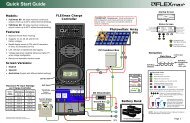
Welcome to <strong>OutBack</strong> <strong>Power</strong> TechnologiesIntroductionThank you for purchasing the <strong>OutBack</strong> <strong>International</strong> <strong>Series</strong> <strong>GFX</strong> <strong>Inverter</strong>/<strong>Charger</strong>. This product offers acomplete power conversion system between batteries and AC power. It can provide backup power orcomplete off-grid service.‣ Battery-to-AC inverting which delivers 230 Vac at 50 Hz‣ AC-to-battery charging‣ Rapid transfer between AC source and inverter outputwith minimal delay time‣ <strong>Inverter</strong> load support for a small AC source‣ 12-, 24-, and 48-volt inverters‣ Wattages from 1.3 kVA to 1.4 kVA‣ Stackable in parallel and three-phase configurations‣ Uses energy from PV, wind, and other renewablesources if appropriate controllers are used‣ Grid-interactive capable‣ CE Compliant for off-grid useFigure 1<strong>International</strong> <strong>Series</strong> <strong>GFX</strong> <strong>Inverter</strong>/<strong>Charger</strong>ModelsThe <strong>International</strong> <strong>Series</strong> <strong>GFX</strong> inverters are designed for harsher environments and can survive casualexposure to the elements. However, enclosed protection is still recommended. These inverters havean internal fan, but do not use outside air for cooling.‣ <strong>GFX</strong>1312E (1.3 kVA output, 12 Vdc)‣ <strong>GFX</strong>1424E (1.4 kVA output, 24 Vdc)‣ <strong>GFX</strong>1448E (1.4 kVA output, 48 Vdc)<strong>Inverter</strong> model numbers use the following naming conventions.‣ Grid-interactive models (all models in this series) begin with the letter G. For example, model <strong>GFX</strong>1424E isgrid-interactive; model VFX3524 is not.‣ The model number includes “FX” as the inverter series.‣ The first two digits show the wattage of that model. For example, “<strong>GFX</strong>1312E” is 1300 watts.‣ The second pair of digits shows the inverter’s nominal DC voltage. For example, “<strong>GFX</strong>1424E” is 24 volts.‣ The letter “E” at the end of the model number indicates an inverter that can deliver 230 Vac at 50 Hz.900-0111-01-00 Rev B 9
IntroductionComponents and AccessoriesTable 2Installed ComponentsBattery Terminal Cover, redBattery Terminal Cover, blackAC Conduit PlateDC Cover (DCC)Components and AccessoriesIncluded in Box<strong>GFX</strong> <strong>Series</strong> Installation Manual (this book)<strong>GFX</strong> <strong>Series</strong> Operator’s Manual“WARNING ELECTRICAL SHOCK” stickerRemote Temperature Sensor (RTS)Silicone Grease PacketDCC (DC COVER)Covers the DC terminal area and provides space tomount other components such as a DC current shunt.AC CONDUIT PLATEConnects to AC conduit for installationswhich do not utilize <strong>OutBack</strong>’s optionalFLEXware conduit boxes.BATTERY TERMINAL COVERProtects terminals from accidental contact. Made of stiff plasticwith a snap-on design.Always keep covers installed during normal operation.When required, remove covers carefully using a flat-bladescrewdriver inserted into the slots on the sides of each cover.The DCC does not replace the battery terminal covers; they mustbe installed in addition to the DCC.Figure 2<strong>GFX</strong> Components10 900-0111-01-00 Rev B
ApplicationsPlanningThe <strong>International</strong> <strong>Series</strong> <strong>GFX</strong> inverters are intended for both off-grid and grid-interactive applications.These models are designed to use a battery bank to store energy. They can work in conjunction withphotovoltaic (PV) panels to harvest solar energy, as well as wind turbines and other renewablesources. These sources charge the battery, which in turn is used by the inverter.In grid-interactive applications, the grid is the primary source of power to run the loads. When excessPV (or another renewable energy source) is available from the batteries, the inverter supports thoseloads with the PV. When the PV exceeds the load requirements, the inverter sells that excess powerback through its input, to the utility grid. When the utility grid is not available, the inverter takes overto run the loads with PV and energy stored in the battery bank.If the inverter is used as the primary source, the grid power will be used when the batteries have beendrained. In this situation, the AC power, PV harvest, or other renewable energy can be used torecharge the battery bank.In off-grid applications, the inverter can use the harvested energy from the battery bank as theprimary power source. An AC generator can also be connected to support the system when required.*Excess AC power not being used by the AC loads. Uses bidirectional AC input for sell-back. Requires a <strong>GFX</strong> <strong>Inverter</strong>/<strong>Charger</strong>programmed for a grid-interactive application.**AC power used for input only. <strong>GFX</strong> inverter should have its grid-interactive feature disabled when using a generator.Figure 3Applications (Example)900-0111-01-00 Rev B 11
PlanningRenewable EnergyThe inverter cannot connect directly to PV, wind turbines, or other renewable sources. The batteriesare the inverter’s primary source of power. However, if these sources are used to charge the batteries,the inverter can use their energy by drawing it from the batteries.The renewable source is always treated as a battery charger, even if all of its power is usedimmediately. The renewable source must have a charge controller or some way to preventovercharging. <strong>OutBack</strong> <strong>Power</strong>’s FLEXmax charge controllers can be used for this purpose, as canother products.Battery BankIMPORTANT:Battery charger settings need to be correct for a given battery type. Always followbattery manufacturer recommendations. Making incorrect settings, or leaving them atfactory default settings, may cause the batteries to be undercharged or overcharged.When planning a battery bank, consider the following:‣ The <strong>GFX</strong> inverters work best with lead-chemistry batteries intended for deep discharge. These includebatteries for marine, golf-cart, and forklift applications. They also include gel-cell batteries and absorbedglass-mat (AGM) batteries. <strong>OutBack</strong> <strong>Power</strong> recommends the use of batteries designed specifically forrenewable energy applications. Automotive batteries are strongly discouraged and will have a short life ifused in inverter applications. Nickel-based batteries are discouraged due to limitations in the <strong>GFX</strong> charger.Lithium-based batteries and other advanced battery technologies may require special considerations.Please contact <strong>OutBack</strong> Technical Support at +1.360.618.4363 before implementing advanced batterytechnologies.‣ These inverters are designed to work with 12-, 24-, or 48-volt battery banks, depending on inverter model.Before constructing a battery bank, check the inverter model and confirm nominal battery voltage.‣ A vented enclosure for the battery bank may be required by electric code and is recommended in mostcases for safety reasons.CAUTION: Hazard to EquipmentBatteries can emit vapors which are corrosive over long periods of time. Installing theinverter in the battery compartment may cause corrosion which is not covered by theproduct warranty. (Sealed batteries may be an exception.)GeneratorThe <strong>GFX</strong> inverters can work with any generator that delivers clean 230 Vac at 50 Hz. <strong>Inverter</strong>s stackedfor three-phase output can work with three-phase generators.‣ The inverter/charger can provide a start signal to control an automatic-start generator. If automaticgenerator starting is required, the generator must be an electric-start model with automatic choke andtwo-wire start capability. For other configurations, additional equipment may be required.‣ In all cases, the inverter may need to be programmed according to the specifications of the generator andthe requirements of the system, using a remote system display. (See the <strong>International</strong> <strong>Series</strong> <strong>GFX</strong> Operator’sManual and the system display manual.) Parameters to be programmed may include generator size,automatic starting requirements, and potential fluctuations in generator AC voltage.12 900-0111-01-00 Rev B
Generator SizingA generator should be sized to provide enough power for all the loads and the battery charger.Planning‣ Available generator power may be limited by ratings for circuit breakers and/or generator connectors.‣ The generator must be able to provide current to all inverters on a given phase or leg. Minimum generatorwattage 1 is usually recommended to be twice the wattage of the inverter system. Many generators may notbe able to maintain AC voltage or frequency for long periods of time if they are loaded more than 80% ofrated capacity.NOTES:1This is the wattage value after deratings for the following: peak verses continuous power, load power factor considerations, fuel type,altitude, and ambient temperature.900-0111-01-00 Rev B 13
PlanningNOTES:14 900-0111-01-00 Rev B
Location and Environmental RequirementsInstallationThe <strong>International</strong> <strong>Series</strong> <strong>GFX</strong> inverters can be located outdoors, but <strong>OutBack</strong> recommends that they beprotected from the environment.‣ If protected from the environment, the inverter can mount in any position or orientation. If exposed to theenvironment, it cannot be placed upside-down, to ensure that water will not accumulate under the DCcover. (It can be mounted in any other position or orientation.)‣ For installations where the inverter may be exposed to water spray, the inverter must be mounted eitherwith the base down (shelf mounting) or with the AC wiring compartment facing down (wall mounting). Ifmounted with the base down, water cannot be allowed to accumulate around the inverter’s base. There is adrainage system on the base of the inverter to dispel condensation. If submerged, water can enter this drainand cause failure.‣ The inverter will perform more efficiently in locations offering plenty of air circulation. The recommendedminimum clearance is 5 to 10 cm (2 to 4 inches) on all sides of the inverter.‣ The inverter will function to all of its specifications if operated in a range of 0°C to 50°C (32°F to 122°F). Notethat the inverter’s maximum wattage will derate in temperatures above 25°C.‣ The inverter will function, but will not necessarily meet its specifications, if operated in a temperature rangeof –40°C to 60°C (–40°F to 140°F). This is also the allowable temperature range for storage. (Thespecifications are listed in the <strong>International</strong> <strong>Series</strong> <strong>GFX</strong> Operator’s Manual.)DimensionsLength 41 cm (16.25”)Width21 cm (8.25”)Height30.5 cm (12”)Figure 4Dimensions900-0111-01-00 Rev B 15
InstallationGroundingWARNING: Shock HazardThe unit must be connected to a grounded, permanent wiring system. If a bond is madebetween neutral and ground make sure only one bond is present in the AC system at anytime. Some codes require the bond to be made at the main panel only.WARNING: Shock HazardFor all installations, the negative battery conductor should be bonded to the groundingsystem at only one point. If the <strong>OutBack</strong> GFDI is present, it can provide the bond.IMPORTANT:<strong>OutBack</strong> products are not designed for use in a positive-grounded system. If it is necessaryto build a positive-ground system with <strong>OutBack</strong> products, contact <strong>OutBack</strong> TechnicalSupport at +1.360.618.4363 before proceeding. Additionally, consult the online forum atwww.outbackpower.com/forum/, where this subject has been discussed extensively.Table 3 Ground Conductor Size and Torque RequirementsTerminal Location Minimum Conductor Size Torque RequirementsChassis Ground/PE 6 mm2 (#10 AWG) or 0.009 in2 2.8 Nm (25 in-lb)DC Box Lug 16 mm2 (#6 AWG) or 0.025 in2 5.1 Nm (45 in-lb)The inverter’s DC ground is a box lug located next tothe negative DC battery terminal. Local codes orregulations may require the DC ground to be runseparately from the AC ground. Also, if present, it willbe necessary to remove the DC Cover before makingthe ground connection.NOTE: The DC ground lug is electrically commonwith the CHASSIS GROUND/PE terminals (see below).Figure 6DC Ground LugThe two CHASSIS GROUND/PE terminals are electricallycommon. If connecting to an external ground bus, onlyone terminal needs to be used. The other terminal maybe used if connecting to a device with its own groundwire, such as a generator.Figure 7Chassis Ground/PE18 900-0111-01-00 Rev B
InstallationDC WiringCAUTION: Equipment DamageNever reverse the polarity of the battery cables. Always ensure correct polarity.CAUTION: Fire HazardAlways install a circuit breaker or overcurrent device on each DC positiveconductor to protect the DC system.Table 4DC Conductor Size and Torque Requirements<strong>Inverter</strong> Nominal DC Amps(Derated 125%)Conductor Size(Minimum)Breaker Size(Minimum)<strong>GFX</strong>1312E 130 70 mm2 (2/0 AWG) or 0.109 in2 175 Adc<strong>GFX</strong>1424E 70 70 mm2 (1/0 AWG) or 0.109 in2 125 Adc<strong>GFX</strong>1448E 35 50 mm2 (#1 AWG) or 0.078 in2 100 AdcTerminal LocationTorque Requirements<strong>Inverter</strong> DC TerminalsBattery Terminals4.0 Nm (35 in-lb)See battery manufacturer’s recommendationsWhen installing DC cables:‣ Make certain DC circuit breakers are turned to the off position, or fuses are removed, before proceeding.‣ Note sizes in Table 4, but refer to applicable codes for absolute cable size recommendations.‣ Battery positive and negative cables should be no longer than 3 meters (10 feet) each, to minimize voltageloss and other effects.‣ Install all overcurrent devices on the positive cable.‣ The cables listed above are for each inverter in a system. In a system with multiple inverters, each inverterrequires its own cables and overcurrent devices of the size indicated.‣ The inverter’s battery terminal is a threaded stud which accepts a ring terminal lug. Use crimped and sealedcopper ring lugs with 0.79 cm (5/16 inch) holes, or use compression lugs.‣ Tie, tape, or twist cables together to reduce self-inductance. Run positive and negative cables through thesame knockouts and conduit.If present, remove the batteryterminal covers. These are made ofstiff plastic with a snap-on design.Remove carefully using a flatscrewdriver inserted into the slotson the sides of each cover.Figure 8 Battery Terminal Covers900-0111-01-00 Rev B 19
InstallationInstall battery cable lug, nuts, and washers in the order illustrated. The battery cable lug should be thefirst item installed on the stud. It should make solid contact with the mounting surface. Do not installhardware in a different order than shown.13 mm NutM8 x 1.25 StudFlat WasherLock WasherMounting SurfaceInsulatorBatteryCable LugFigure 9Required Order of Battery Cable HardwareCAUTION: Fire HazardNever install extra washers or hardware between the mounting surface and thebattery cable lug. The decreased surface area can build up heat.20 900-0111-01-00 Rev B
InstallationAC WiringTable 5AC Conductor Size and Torque RequirementsConductor Size RecommendationMinimum 6 mm2 (#10 AWG) or 0.009 in2Torque Requirements4.0 Nm (35 in-lb)The AC Hot Out terminalconnects to the load panel. Itcan carry up to 30 amps usingthe inverter’s transfer relay. Usethe inverter wattage todetermine actual maximumload. Size the circuit breakersaccordingly.The AC Hot In terminal bringspower from the AC source. Itpowers both battery chargerand loads. Use the sourceamperage to determine actualmaximum draw. Size circuitbreakers accordingly.The two Neutralterminals areelectrically common.If connecting to anexternal ground bus,only one terminalneeds to be used. (Anexternal bus is oftenplaced in the mainelectrical panel, whichis the Loads panelshown in Figure 11).Use the other terminalif connecting to adevice with its ownneutral wire, such as agenerator.Figure 10AC TerminalsAll system wiring must comply with national and local codes and regulations.900-0111-01-00 Rev B 21
InstallationAC SourcesThe inverter’s transfer relay is normally set to provide inverter power to the output. When an ACsource is connected and accepted, the internal transfer relay switches to transfer the AC source powerto the loads. (See the Operator’s Manual for the inverter’s acceptance criteria.)Figure 11Multiple AC SourcesThe inverter has a single set of AC terminals which are intended to connect to a single AC source.It cannot be directly wired to more than one AC source at the same time. If multiple sources areused, it is usually required to have a selector switch that changes from one to the next. The switchshould be the type which disconnects from one source before contacting another. This prevents therisk of connecting to two out-of-phase sources at the same time or connecting them to each other.IMPORTANT:When installing a generator, it is recommended to turn off the <strong>GFX</strong> inverter’s Sell feature.See the system display manual for instructions.22 900-0111-01-00 Rev B
InstallationAccessory WiringThe AC Wiring Compartment Board has ports forboth the Remote Temperature Sensor (RTS) andthe system display. The system display port islabeled MATE/HUB.If a HUB is in use, it occupies the inverter’sMATE/HUB port.RTS cable (RJ11,4-conductor,telephone)MATE cable (RJ45,8-conductor, CAT5non-crossover)RTS portMATE/HUB portSee the Operator’sManual for moreinformation onthe RTS.Figure 12Accessory ConnectionsAdditionalPortsMATEportWhen a HUB occupies the inverter’s MATE/HUB port, the systemdisplay connects directly to the HUB. (If the system display is aMATE, do not connect it during initial startup. See theOperator’s Manual for more information.)<strong>Inverter</strong>s plug into ports 1 and above. Charge controllers andother devices plug into additional ports after the last inverter isconnected. See Stacking on page 28 for information onconnecting inverters. See the HUB manual for other devices.The INVERTER ON/OFF jumper bridges two pins. This jumper (JP1)parallels the two INVERTER ON/OFF terminals on the ControlWiring Terminal Block. If either set of connections is closed, theinverter is ON. (Because the jumper is factory-installed, the inverterusually remains ON unless given a command by the system display.)Removing the jumper will turn theinverter OFF. To remove the jumper,use long-nose pliers or a similar tool.Jumper OnJumper OffOnce the plastic INVERTER ON/OFFjumper has been removed, the INVERTERON/OFF terminals on the Control WiringTerminal Block can be used to wire amanual on/off switch.Figure 13ON/OFF Jumper and Connections900-0111-01-00 Rev B 23
InstallationAUX WiringThe AUX+ and AUX– terminals are a switched 12 Vdc supply. The AUX can respond to many criteriaand control many functions. These include cooling fans, vent fans, load diversion, fault alarms, andautomatic generator control. The AUX output can also be controlled externally through the systemdisplay. (For generator control, see the next page. For all other functions, see the system displaymanual and the <strong>International</strong> <strong>Series</strong> <strong>GFX</strong> Operator’s Manual.) The AUX output can only control onefunction at a time.The terminals can supply up to 0.7 amps at 12 Vdc (8.4 watts). This is sufficient to drive a small fan, or arelay which can control a larger device. The terminals accept up to 2.5 mm2 (#14 AWG) wire.The AUX circuit contains electronic overcurrent protection, which resets after being overloaded. Noadditional fuses are required for the AUX terminals.In this example, the AUXdirectly drives a 12-volt ventfan. The + and – wires onthe fan are connected to theAUX+ and AUX– terminals.The AUX LEDilluminates when theAUX outputbecomes active.FanFigure 14AUX Connections for Vent Fan (Example)In this example, the AUX output drives a relaythat diverts wind power. The relay’s coil isconnected to the AUX+ and AUX– terminals.When the AUX output closes the relay (based onbattery voltage), the relay diverts the excesswind power to a water heating element.TurbineRelayNote: Relays and elements shown are examples onlyand may vary depending on the installation.ElementFigure 15AUX Connections for Diversion (Example)24 900-0111-01-00 Rev B
InstallationAutomatic Generator Start (AGS)The AUX terminals can be used to perform “two-wire” generator start. A two-wire-start generator isthe simplest type, where most of the circuits are automated. It usually has a single switch with twopositions that is turned ON to start, OFF to stop.Either the system display or the FLEXnet DC can be programmed to perform automatic generator startusing the AUX terminals. See the system display or FLEXnet manuals for programming instructions.Two-Wire-StartThe 12 Vdc signal provided by the AUX output can be switched on and off to provide a start signal. Itis not usually recommended to connect the AUX terminals directly to the generator, but to use themto energize the coil of a 12 Vdc automotive or similar relay.Depicted is the <strong>OutBack</strong> FLEXware Relay Assembly, which is sold for this purpose. The relay contactscan serve in place of the generator’s start switch. The battery shown below is depicted for clarity. Inmost cases, it is part of the generator’s internal starting circuit and is not an external component.The drawing below is one example of a possible arrangement. Specific arrangements, relays, andother elements depend on the requirements of the installation and of the generator.RelayCoilRelayContactsStartingTerminals11GeneratorBatteryTwo-Wire-StartGeneratorFigure 16Two-Wire Generator Start (Example)900-0111-01-00 Rev B 25
InstallationThree-Wire-StartA “three-wire-start” generator has two or more starting circuits. It usually has a separate switch orposition for cranking the generator. A three-wire generator has fewer automated functions than atwo-wire. It usually requires multiple controls for starting, running, or stopping. The AUX terminalscannot control this type of generator without using a three-wire to two-wire conversion kit.Atkinson Electronics (http://atkinsonelectronics.com) is one company that makes these kits. TheAtkinson GSCM-Mini is intended to work with <strong>OutBack</strong> inverters.The drawing below is one example of a possible arrangement. Specific arrangements, relays, andother elements depend on the requirements of the installation and of the generator.AtkinsonGSCM-MiniThree-Wire-StartGeneratorFigure 17Three-Wire Generator Start (Example)26 900-0111-01-00 Rev B
InstallationSingle-<strong>Inverter</strong> AC InstallationsWhen installing an inverter AC system, the following rules must be observed.‣ All overcurrent devices must be sized for 30 Aac or less.‣ All wiring must be sized for 30 Aac or more.‣ All output circuit breakers must be sized appropriately for loads and inverter wattage.NOTES:1. Neutral (common) conductor may be connected from only one inverterneutral terminal to a common bus bar in the AC conduit box.2. Colors depicted here may be different from wiring standards.Figure 18Single-<strong>Inverter</strong> Wiring900-0111-01-00 Rev B 27
InstallationMultiple-<strong>Inverter</strong> AC Installations (Stacking)Installing multiple inverters in a single AC system allows larger loads than a single inverter can handle.This requires stacking. Stacking inverters does not refer to physically placing one on top of another. Itrefers to how they are wired within the system and then programmed to coordinate activity. Stackingallows all units to work together as a single system.Examples of stacking configurations include “parallel” and “three-phase” configurations.Stacking ConnectionsStacking requires an <strong>OutBack</strong> HUB product, as well as a system display, such as the <strong>OutBack</strong> MATE orMATE3. (If the MATE is used, it must have firmware revision 4.1.6 or above.) A system using four orfewer units may use the HUB4. <strong>Systems</strong> using up to ten units require the HUB10. All interconnectionsare made using CAT5 noncrossover cable.HUB4Additional Ports Port 1 MATE PortMATE3MATEFigure 19<strong>OutBack</strong> HUB4, MATE3, and MATEEach inverter must be assigned a status — “master” or “slave”. The master is the primary and mostheavily used unit. The master inverter’s MATE/HUB port must connect to port 1 on the HUB.Slave inverters provide assistance when the loads are more than the master can handle alone. Slavesplug into ports 2 and above on the HUB. In general, it does not matter which slave connects to whichport. However, it is always important to keep track of units and ports for programming purposes. Seethe system display manual for more information.Programming involves using the system display to assign a status and stacking value to the inverteron each port. Each inverter is assigned to power a specified phase of the system. These assignmentscan be changed at any time as long as the master is plugged into port 1.IMPORTANT:‣ The master inverter must always be connected to port 1 on the HUB. Connecting itelsewhere, or connecting a slave to port 1, will result in backfeed or output voltageerrors which will shut the system down immediately.‣ Installing multiple inverters without stacking them (or stacking them incorrectly) willresult in similar errors and shutdown.‣ Although stacking allows greater capacity, the loads, wiring, and overcurrent devicesmust still be sized appropriately. Overloading may cause circuit breakers to open orthe inverters to shut down.28 900-0111-01-00 Rev B
InstallationParallel Stacking (Dual-Stack and Larger)In parallel stacking, two or more inverters are stacked to create a single, common 230 Vac bus.‣ All inverters share a common input (AC source) and run loads on a common output.‣ Up to ten inverters may be installed in a parallel arrangement. The example on this page shows threeinverters. The wiring diagram on the next page shows four.1.3 kVA 230 Vac 1.3 kVA 230 Vac 1.3 kVA 230 Vac3.9 kVA230 VacFigure 20Example of Parallel Stacking Arrangement (Three <strong>Inverter</strong>s)When installing a parallel system, the following rules must be observed.‣ Parallel stacking requires a system display and a HUB.‣ The inverter that is mounted physically lowest is always the master and is programmed as Master. (See thesystem display manual for programming.) Mounting below the other inverters allows the master to avoidheat buildup and remain relatively cool as it sees the greatest duty cycle.‣ The master must be connected to port 1 of the HUB. Other inverters must not be selected as master.‣ All slave inverters, regardless of quantity, should be selected as OB Slave L1 during programming.‣ All overcurrent devices must be sized for 30 Aac or less.‣ All wiring must be sized for 30 Aac or more.‣ All output circuit breakers must be sized appropriately for loads and inverter wattage.‣ All inverters must be of the same model.‣ The AC input (generator or utility grid) must be 230 Vac at 50 Hz (single-phase).‣ When wiring the AC source to the inverters, local codes may require the inverter circuits to be located at theopposite end of the panel from the main circuit breaker. This prevents overloading of the AC bus.900-0111-01-00 Rev B 29
InstallationNOTES:1. Neutral (common) conductor may beconnected from only one inverterneutral terminal to a common busbar in the AC conduit box.2. Colors shown here may be differentfrom wiring standards.Figure 21Parallel Wiring (Four <strong>Inverter</strong>s)30 900-0111-01-00 Rev B
InstallationThree-Phase StackingIn three-phase stacking, inverters are stacked to create three separate 230 Vac output legs in a wyeconfiguration.‣ The output of each inverter is 120° out of phase from the others. Any two outputs produce 400 Vacbetween them. The outputs can be used to power three-phase loads when all inverters work together.‣ Only three inverters, one per phase, may be installed in a three-phase arrangement.1.3 kVA 230 Vac1.3 kVA230 Vac1.3 kVA 230 Vac1.3 kVA230 Vac3.9 kVA400 Vac1.3 kVA 230 Vac1.3 kVA230 VacFigure 22Example of Three-Phase Stacking Arrangement (Three <strong>Inverter</strong>s)When installing a three-phase system, the following rules must be observed.‣ Three-phase stacking requires a system display and a HUB.‣ The inverter that is mounted physically lowest is always the master and is programmed as Master. (See thesystem display manual for programming.) Mounting below the other inverters allows the master to avoidheat buildup and remain relatively cool as it sees the greatest duty cycle.‣ The master must be connected to port 1 of the HUB. Other inverters must not be selected as master.‣ One slave inverter must be programmed as 3p Classic B. The other must be programmed as 3p Classic C.(See the system display manual for programming.)‣ The inverters should be wired to the loads and to the AC sources in phase order. The master should bephase A, the first slave should be phase B, and the second slave should be phase C.‣ All overcurrent devices must be sized for 30 Aac or less.‣ All wiring must be sized for 30 Aac or more.‣ All output circuit breakers must be sized appropriately for loads and inverter wattage.‣ All inverters must be of the same model.‣ The AC input (generator or utility grid) must be 230/400 Vac at 50 Hz (a three-phase wye configuration).‣ When wiring the AC source to the inverters, local codes may require the inverter circuits to be located at theopposite end of the panel from the main circuit breaker. This prevents overloading of the AC bus.IMPORTANT:Although the HUB manual states that it is necessary to move the HUB’s jumper to thethree-phase position, that statement is not applicable for this model. The jumper mustbe left in its original position.900-0111-01-00 Rev B 31
InstallationNOTES:1. Neutral (common) conductor may be connected from only oneinverter neutral terminal to a common bus bar in the AC conduit box.2. Colors shown here may be different from wiring standards.Figure 23Three-Phase Wiring (Three <strong>Inverter</strong>s)32 900-0111-01-00 Rev B
Functional TestInstallationOnce the mounting, wiring, and other installation steps are completed, proceed to the <strong>International</strong><strong>Series</strong> <strong>GFX</strong> Operator’s Manual. The Operator’s Manual has steps for powering up and performing afunctional test on the inverter system, as well as powering down and adding new devices to anexisting system.Refer to the system display manual for programming instructions and menus.900-0111-01-00 Rev B 33
InstallationNOTES:34 900-0111-01-00 Rev B
IndexAAC Conduit Plate................................................................12AC Terminals .......................................................................19AC Wiring .............................................................................23AGS...........................................................................................2Applications ........................................................................13Audience ................................................................................1Automatic Generator Start........................................ 2, 26AUX...........................................................................................2AUX Terminals ....................................................................19BBattery Bank ................................................................... 4, 14Battery Terminal Covers...........................................12, 21CCommunication Cables............................................24, 30Components .......................................................................12Conductor SizeAC Conductors..............................................................23DC Conductors .............................................................21Ground Conductors ....................................................20Control Wiring Terminal Block ......................................19DDC Cover (DCC) ...........................................................12, 17DC Terminals................................................................19, 22DC Wiring .............................................................................21Definitions..............................................................................2Dimensions..........................................................................17Diversion Control...............................................................25DrawingsGeneral System Layout..............................................13Parallel-Stacked System.............................................33Single-<strong>Inverter</strong> System...............................................29Three-Phase System....................................................36DVM................................................................................... 2, 18EEnvironmental Requirements .......................................17FFeatures ................................................................................11Functional Test...................................................................37GGenerator ................................... 13, 14, 23, 26, 29, 31, 34Sizing................................................................................15GFDI................................................................................... 2, 20Grid-Interactive ............................................................. 2, 13Grounding.....................................................................19, 20HHUB .................................................................................24, 30JJumper JP1 ...................................................................19, 24LLED Indicators................................................................ 2, 19Location................................................................................17MMATE........................................................................19, 24, 30Models...................................................................................11Mounting..............................................................................18Multiple AC Sources..........................................................23OOn/Off Switch, Installing .................................................24PParallel Stacking.................................................................31Ports, RJ45 and RJ11..................................................19, 24900-0111-01-00 Rev B 35
IndexRRecycling Information ....................................................... 6Regulatory ............................................................................. 6Remote System Display ..............................................2, 14Remote Temperature Sensor (RTS) ...........2, 12, 19, 24Renewable Energy............................................................14SSafety....................................................................................... 1Battery............................................................................... 4General.............................................................................. 2<strong>Inverter</strong>.............................................................................. 3Personal............................................................................ 3Stacking................................................................................30Parallel.............................................................................31Three-Phase...................................................................34Symbols Used....................................................................... 1System Display.2, 14, 19, 23, 24, 25, 26, 30, 31, 34, 37TTemperatures .....................................................................17Terms and Definitions ....................................................... 2Test.........................................................................................37Three-Phase Stacking ......................................................34Tools Required ...................................................................18Torque RequirementsAC Terminals .................................................................23DC Terminals.................................................................21Ground Terminals........................................................20UUtility Grid............................................2, 13, 23, 29, 31, 34VVent Fan ...............................................................................25WWiringAC Connections ...........................................................23AUX Connections ........................................................25DC Connections ...........................................................21Ground Connections..................................................20Parallel (Four <strong>Inverter</strong>s) .............................................33Three-Phase (Three <strong>Inverter</strong>s) .................................36XXCT.........................................................................................1936 900-0111-01-00 Rev B
Index900-0111-01-00 Rev B 37
North America:5917 – 195 th St NE, #7Arlington, WA 98223 USA+1.360.435.6030900-0111-01-00 Rev B