OPERATOR'S INSTRUCTION MANUAL DIGITAL MULTIMETER
OPERATOR'S INSTRUCTION MANUAL DIGITAL MULTIMETER
OPERATOR'S INSTRUCTION MANUAL DIGITAL MULTIMETER

You also want an ePaper? Increase the reach of your titles
YUMPU automatically turns print PDFs into web optimized ePapers that Google loves.
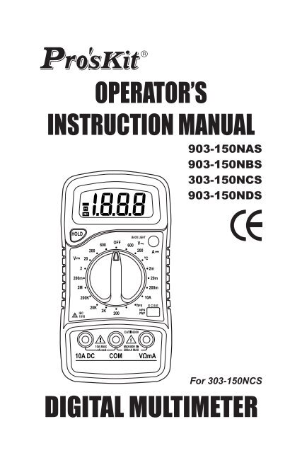
OPERATOR’S<strong>INSTRUCTION</strong> <strong>MANUAL</strong>903-150NAS903-150NBS303-150NCS903-150NDSFor 303-150NCS<strong>DIGITAL</strong> <strong>MULTIMETER</strong>
SAFETY INFORMATIONThis multimeter has been designed according to IEC 1010concerning electronic measuring instruments with an overvoltagecategory (CAT II) and pollution 2. Follow all safety and operatinginstructions to ensure that the meter is used safely and is kept ingood operating condition. Full compliance with safety standardscan be guaranteed only with test leads supplied. If necessary, theymust be replaced with the type specified in this manual.SAFETY SYMBOLSImportant safety information, refer to the operating manual.Dangerous voltage may be present.Earth ground.Double insulation (Protection class II).200mA/250VFuse must be replaced with rating specified in the manual.MAINTENANCE• Before opening the case, always disconnect test leads from allenergized circuits.• For continue protection against fire; replace fuse only with thespecified voltage and current ratings: F 200mA/250V(QuickActing)• Never use the meter unless the back cover is in place andfastened completely.• Do not use abrasives or solvents on the meter. To clean it usinga damp cloth and mild detergent only.
DURING USE• Never exceed the protection limit values indicated in specificationsfor each range of measurement.• When the meter is linked to measurement circuit, do not touchunused terminals.• Never use the meter to measure voltages that might exceed600V above earth ground in category II installations.• When the value scale to be measured is unknown beforehand,set the range selector at the highest position.• Before rotating the range selector to change functions, disconnecttest leads from the circuit under test.• When carrying out measurements on TV or switching powercircuits always remember that there may be high amplitude voltagespulses at test points, which can damage the meter.• Always is careful when working with voltages above 60V dcor 30V ac rms. Keep fingers behind the probe barriers whilemeasuring.• Before attempting to insert transistors for testing, always be surethat test leads have been disconnected from any measurementcircuits.• Components should not be connected to the hFE socket whenmaking voltage measurements with test leads.• Never perform resistance measurements on live circuits.GENERAL DESCRIPTIONThe meter is a handheld 3 1/2 digital multimeter for measuring DCand AC voltage, DC current, Resistance, Diode, Transistor andContinuity Test with battery operated.The Back light of display is optional.
Function 903-150NAS 903-150NBS 303-150NCS 903-150NDSAC Voltage V~ • • • •DC Voltage V • • • •DC Current A • • • •Resistance Ω • • • •Diode • • • •Transistor hFE test • • • •Continuity • • •Temperature ºC•HOLD • • • •BACK LIGHT•1423567
FRONT PANEL DESCRIPTIONDisplay1 3 1/2 digit, 7 segment, 15mm high LCD.2 Back light (option)When this button is pushed, the Back light of display is on. Afterabout 5 seconds, the Back light is self-off. The Back light is onagain, just push this button once.3 Rotary switchThis switch is used to select functions and desired ranges aswell as to turn on/off the meter.4 Hold buttonWhen this button is pushed, the display will keep the last readingand " " symbol will appear on the LCD until pushing it again.5 "10A" jackPlug in connector for red test lead for 10A measurement."COM" jack6 Plug in connector for black (negative) test lead. "VΩmA" jack7 Plug in connector for red (positive) test lead for voltage, resistanceand current (except 10A) measurements.SPECIFICATIONSAccuracy is specified for a period of one year after calibration andat 18 to 28°C(64°F to 82°F) with relative humidity to 80%.GENERALMaximum voltage betweenterminals and earth ground : CAT II 600VFuse protection: F 200mA/250VPower: 9V battery, NEDA 1604 or 6F22Display: LCD, 1999 counts, updates 2-3/sec.Measuring method : Dual-slope integration A/D converterOverrange Indication : Only figure "1" on the displayPolarity indication : "-" displayed for negative polarityOperating Environment : 0 to 40ºCStorage temperature : -10ºC to 50ºC.Low battery indication : " " appears on the displaySize: 138mm×69mm×31mmWeight: Approx.170g.
DC VOLTAGERange Resolution Accuracy200mV 100µV ±0.5% of rdg ± 2 digits2V 1mV ±0.5% of rdg ± 2 digits20V 10mV ±0.5% of rdg ± 2 digits200V 100mV ±0.5% of rdg ± 2 digits600V 1V ±0.8% of rdg ± 2 digitsOverload Protection: 250V rms. For 200mV range and 600V dcor rms. ac for other ranges.DC CURRENTRange Resolution Accuracy200μA 0.1µA ±1% of rdg ± 2 digits2mA 1µA ±1% of rdg ± 2 digits20mA 10µA ±1% of rdg ± 2 digits200mA 100µA ±1.5% of rdg ± 2 digits10A 10mA ±3% of rdg ± 2 digitsOverload Protection: F 200mA/250V fuse. (10A range unfused)*303-150NCS DC 200µA ExceptedAC VOLTAGERange Resolution Accuracy200V 100mV ±1.2% of rdg ± 10 digits2600V 1V ±1.2% of rdg ± 10 digitsOverload Protection: 600V dc or rms. ac for all ranges.Frequency range: 40Hz to 400Hz. Response: Average responding,calibrated in rms. of a sine wave.DIODE & CONTINUITY(*903-150NAS Excepted)RangeDescriptionIf continuity exists (about less than 1.5kΩ), built-in buzzerwill sound.Show the approx. forward voltage drop of the diode.
Overload Protection: 250V dc or rms. ac.RESISTANCERange Resolution Accuracy200Ω 0.1Ω ±0.8% of rdg ± 3 digits2kΩ 1Ω ±0.8% of rdg ± 2 digits20kΩ 10Ω ±0.8% of rdg ± 2 digits200kΩ 100Ω ±0.8% of rdg ± 2 digits2MΩ 1kΩ ±1.0% of rdg ± 2 digitsMaximum Open Circuit Voltage: 3.2VOverload Protection: 250V dc or rms. ac for all ranges.TRANSISTOR hFE TEST (0-1000)Range Test Range Test Current Test VoltageNPN & PNP 0-1000 Ib=10μA Vce=3VTEMPERATURE (For 303-150NCS only)Range Resolution Test Range AccuracyºC 1ºC-20ºC to 0ºC-0ºC to 400ºC400ºC to 1000ºCTEMPERATURE (For 303-150NCS only)±1.0% of rdg ± 2 digits±1.0% of rdg ± 3 digits±2.0% of rdgRange Resolution Test Range AccuracyºF 1ºF-4ºF to 32ºF32ºF to 752ºF752ºF to 1832ºF±10% of rdg ± 2 digits±1.0% of rdg ± 3 digits±2.0% of rdgOPERATING <strong>INSTRUCTION</strong>S DC VOLTAGE MEASURE-MENT1. Connect the red test lead to the "V.Ω.mA" jack and the blacklead to the "COM" jack.2. Set rotary switch at desired DCV position. If the voltage to bemeasured is not known beforehand, set range switch at thehighest range position and then reduce it until satisfactoryresolution is obtained.3. Connect test leads across the source or load being measured.4. Read voltage value on the LCD display along with the polarity ofthe red lead connection.
DC CURRENT MEASUREMENT1. Connect the red test lead to the "V.Ω.mA" jack and the blacktest lead to "COM" jack. (For measurements between 200mAand 10A, remove red lead to "10A" jack.)2. Set the rotary switch at desired DCA position.3. Open the circuit in which the current is to be measured, andconnect test leads in series with the circuit.4. Read current value on LCD display along with the polarity of redlead connection.AC VOLTAGE MEASUREMENT1. Connect the red test lead to "V.Ω. mA" jack and the black testlead to the "COM" jack.2. Set the rotary switch at desired ACV position.3. Connect test leads across the source or load being measured.4. Read voltage value on the LCD display.RESISTANCE MEASUREMENT1. Connect the red test lead to "V. Ω. mA" jack and black test leadto the "COM" jack. (The polarity of red lead is positive "+".)2. Set the rotary switch at desired "Ω" range position.3. Connect test leads across the resistor to be measured and readLCD display.4. If the resistance being measured is connected to a circuit turnoff power and discharge all capacitors before applying testprobes.DIODE TEST1. Connect the red test lead to "V.Ω.mA" jack and the black testlead to the "COM" jack (The polarity of red lead is positive "+".).2. Set the rotary switch at " " position.3. Connect the red test lead to the anode of the diode to be testedand the black test lead to the cathode of the diode. The approx.forward voltage drop of the diode will be displayed. If the connectionis reversed, only figure "1" will be shown.
TRANSISTOR TEST1. Set the rotary switch at "hFE" position.2. Determine whether the transistor under testing is NPN or PNPand locate the emitter base and collector leads. Insert the leadsinto proper holes of the hFE socket on the front panel.3. Read the approximate hFE value at the test condition of basecurrent 10μA and Vce 3V.NOTE:To avoid electrical shock, remove test leads from measurementcircuits before testing a transistor.AUDIBLE CONTINUITY TEST1. Connect red test lead to "V.Ω.mA", black test lead to “COM”.2. Set range switch to " " position.3. Connect test leads to two points of circuit to be tested. If continuityexists, built-in buzzer will sound.MEASURING TEMPERATURE1. If the meter is the ºC function, set the rotary switch at ºC. Position.If it is the ºF function, set the rotary switch at ºF Position.The LCD display will show the current environment temperature.2. Connect the red lead of "K" type thermocouple into the"V.Ω.mA" jack and the black lead of "K" type thermocouple intothe "COM" jack.3. Read temperature value on the LCD display.WARNINGTo avoid electric shock, be sure the thermocouple has beenremoved before changing to another function measurement.
BATTERY & FUSE REPLACEMENTIf " " appears on display, it indicates that the battery shouldbe replaced.Fuse rarely need replacement and blow almost always as aresult of operator’s error.To replace battery & fuse (200mA/250V) remove the 2 screwsin the bottom of the case. Simply remove the old, and replacewith a new one.Be careful to observe battery polarity.WARNINGBefore attempting to open the case, always be sure that testleads have been disconnected from measurement circuits.Close case and tighten screws completely before using themeter to avoid electrical shock hazard.ACCESSORIES• Operator’s instruction manual• Set of test leads• Gift box• 9 volt battery. NEDA 1604 6F22 006P type• "K" type thermocouple(For 303-150NCS only)• Holster (option)10
7. VΩmA 插 孔安 全 資 訊903-150NAS、903-150NBS、303-150NCS 和 903-150NDS 數 位多 用 錶 是 根 據 IEC1010 600V(CAT II) 和 污 染 等 級 2 設 計 的 。 為 保 證 儀錶 能 準 確 安 全 使 用 , 請 認 真 閱 讀 使 用 說 明 書 。安 全 標 誌200mA/250V重 要 的 安 全 資 訊 , 應 參 閱 說 明 書高 壓 危 險地雙 重 絕 緣 (II 類 安 全 設 備 )保 險 絲 必 須 按 說 明 書 指 定 的 規 格 更 換使 用 注 意 事 項• 儀 錶 只 能 和 所 配 備 的 測 試 錶 棒 一 起 使 用 才 符 合 安 全 標 準 的 要 求 。 如測 試 錶 棒 破 損 需 要 更 換 , 必 須 換 上 同 型 號 或 相 同 電 氣 規 格 的 測 試 錶棒 。• 切 勿 超 過 每 個 量 程 所 規 定 的 輸 入 極 限 值 。• 當 儀 錶 正 在 測 量 時 , 不 要 觸 及 沒 有 使 用 的 輸 入 端 。• 在 不 能 確 定 被 測 量 的 大 小 範 圍 時 , 將 功 能 量 程 開 關 置 於 最 大 量 程 位置 。• 在 功 能 量 程 開 關 轉 換 之 前 , 應 使 測 試 錶 棒 與 被 測 電 路 處 於 開 路 狀 態 。• 進 行 線 上 電 阻 測 量 前 , 應 關 斷 電 路 中 所 有 電 源 並 將 所 有 電 容 器 放 電 。• 測 量 高 於 60V 直 流 30V 交 流 以 上 的 電 壓 時 , 務 必 小 心 , 切 記 手 指 不 要超 過 測 試 錶 棒 擋 手 部 份 。• 測 量 電 視 機 或 開 關 電 源 時 , 應 注 意 電 路 中 可 能 存 在 會 損 壞 儀 表 的 脈衝 。• 在 測 試 電 晶 體 前 , 必 須 確 保 測 試 錶 棒 沒 有 連 接 到 任 何 被 測 試 電 路 。12
• 在 測 試 錶 棒 測 量 電 壓 前 , 必 須 確 保 電 子 元 件 連 接 在 電 晶 體 測 試 座 上 。維 護• 在 打 開 後 蓋 之 前 , 測 試 錶 棒 應 斷 開 測 量 電 路 。• 為 保 護 儀 錶 的 內 部 線 路 , 更 換 保 險 絲 必 須 使 用 相 同 的 規 格 , 本 系列 儀 表 使 用 的 保 險 絲 規 格 為 :F 200mA/250V( 快 速 )。• 在 後 蓋 未 蓋 妥 , 螺 絲 未 擰 緊 前 , 切 勿 使 用 儀 錶 。• 清 潔 儀 錶 只 能 使 用 溼 布 和 少 量 清 滌 劑 , 切 忌 用 化 學 溶 劑 擦 表 殼 。• 如 觀 察 到 有 任 何 異 常 , 該 儀 錶 應 立 即 停 止 使 用 並 送 維 修 。技 術 指 標準 確 度 :±% 讀 數 字 數 , 保 證 期 1 年 。環 境 溫 度 :18°C 至 28°C 。 環 境 溼 度 :80%。一 般 特 性 :電 壓 輸 入 端 和 地 之 間 最 大 電 壓 :CAT II 600V保 險 管電 源最 大 顯 示 值 :1999過 量 程 指 示 :"1":F 200mA/250V極 性 顯 示 : 負 極 性 顯 示 "-"工 作 溫 度 :0 到 40ºC儲 存 溫 度 :10ºC 到 50ºC:9V 電 池 ,NEDA 1604 或 6F22低 電 壓 指 示 : 顯 示 器 顯 示 " "外 型 尺 寸重 量:138mm×69mm×31mm: 約 170g13
直 流 電 壓 測 量量 程 分 辨 力 準 確 度200mV 100µV ±0.5% 讀 數 ± 2 字2V 1mV ±0.5% 讀 數 ± 2 字20V 10mV ±0.5% 讀 數 ± 2 字200V 100mV ±0.5% 讀 數 ± 2 字600V 1V ±0.8% 讀 數 ± 2 字超 載 保 護 :200mV 量 程 250V dc 或 rms; 其 餘 量 程 600V dc 或 rms。直 流 電 流 測 量量 程 分 辨 力 準 確 度200μA 0.1µA ±1% 讀 數 ± 2 字2mA 1µA ±1% 讀 數 ± 2 字20mA 10µA ±1% 讀 數 ± 2 字200mA 100µA ±1.5% 讀 數 ± 2 字10A 10mA ±3% 讀 數 ± 2 字超 載 保 護 :F 200mV/250V 保 險 絲 (10A 量 程 無 保 險 絲 )。303-150NCS 無 200µA 檔 。交 流 電 壓 測 量量 程 分 辨 力 準 確 度200V 100mV ±1.2% 讀 數 ± 10 字600V 1V ±1.2% 讀 數 ± 10 字超 載 保 護 :600V dc 或 rms。 頻 率 範 圍 :40Hz 到 400Hz。顯 示 : 平 均 值 ( 正 弦 波 有 效 值 )。14
電 阻量 程 分 辨 力 準 確 度200Ω 0.1Ω ±0.8% 讀 數 ± 3 字2kΩ 1Ω ±0.8% 讀 數 ± 2 字20kΩ 10Ω ±0.8% 讀 數 ± 2 字200kΩ 100Ω ±0.8% 讀 數 ± 2 字2MΩ 1kΩ ±1.0% 讀 數 ± 2 字最 大 開 路 電 壓 :3.2V超 載 保 護 :250V dc 或 rms二 極 體 和 電 路 通 斷 測 試 (903-150NAS 無 此 功 能 )量 程說 明導 通 電 阻 小 於 1.5kΩ, 機 內 蜂 鳴 器 響 。顯 示 近 似 二 極 體 正 向 電 壓 值 。超 載 保 護 :250V dc 或 rms. ac電 晶 體 hFE 測 試 (0-1000)量 程 測 試 範 圍 測 試 電 流 測 試 電 壓NPN & PNP 0-1000 Ib=10μA Vce=3V溫 度 測 試 ( 僅 303-150NCS 有 此 功 能 )量 程 分 辨 力 測 量 準 確 度ºC 1ºC-20ºC 到 0ºC-0ºC 到 400ºC400ºC 到 1000ºC±1.0% 量 程 ± 2 字±1.0% 量 程 ± 3 字±2.0% 量 程15
使 用 方 法操 作 前 注 意 事 項 :1. 接 通 電 源 , 先 檢 查 9V 電 池 , 如 果 電 池 電 壓 不 足 ," " 將 顯示 在 顯 示 器 上 , 這 時 則 需 要 更 換 電 池 。 如 果 顯 示 器 上 沒 有 顯 示 "", 則 按 以 下 步 驟 操 作 。2. 測 試 錶 棒 插 孔 旁 邊 的 " " 符 號 , 表 示 輸 入 電 壓 或 電 流 不 應 超 過指 示 值 , 這 是 為 了 保 護 內 部 線 路 免 受 損 傷 。3. 測 試 之 前 , 功 能 量 程 開 關 應 置 於 您 所 需 要 的 量 程 。直 流 電 壓 測 量1. 將 紅 色 錶 棒 插 入 "VΩmA" 插 孔 , 黑 色 錶 棒 插 入 "COM" 插 孔 。2. 將 功 能 量 程 開 關 置 於 V 量 程 範 圍 , 並 將 測 試 錶 棒 連 接 到 待 測 試電 源 或 負 載 上 , 紅 色 錶 棒 所 接 端 的 極 性 將 同 時 顯 示 於 顯 示 器 上 。注 意1. 如 果 被 測 量 電 壓 範 圍 事 先 不 知 道 , 請 將 功 能 量 程 開 關 置 於 最 大 量程 , 然 後 逐 漸 降 低 直 至 取 得 滿 意 的 分 辨 力 。2. 如 果 顯 示 器 只 顯 示 "1" , 這 表 示 已 經 過 量 程 , 功 能 量 程 開 關 應 置於 更 高 量 程 。3. 不 要 輸 入 高 於 600V 的 電 壓 , 顯 示 更 高 電 壓 是 可 能 的 , 但 有 損 壞 儀錶 內 部 線 路 的 危 險 。4. 在 測 量 高 壓 電 時 , 要 特 別 注 意 避 免 觸 電 。16
直 流 電 流 測 量1. 將 黑 色 錶 棒 插 入 COM 插 孔 , 當 被 測 電 流 不 超 過 200mA 時 , 紅 色色 錶 棒 插 入 "V. .mA" 插 孔 。 如 果 被 測 電 流 在 200mA 和 10A 之間 , 則 將 紅 色 錶 棒 插 入 10A 插 孔 。2. 將 功 能 量 程 開 關 置 於 所 需 要 的 A 量 程 位 置 , 並 將 測 試 錶 棒 串 連接 入 到 待 測 負 載 上 , 電 流 值 顯 示 器 紅 色 錶 棒 連 接 的 極 性 。注 意1. 如 果 被 測 電 流 範 圍 事 先 不 知 道 , 請 將 功 能 量 程 開 關 置 於 最 大 量程 , 然 後 逐 漸 降 低 直 至 取 得 滿 意 的 分 辨 力 。2. 如 果 顯 示 器 只 顯 示 "1" , 這 表 示 已 經 過 量 程 , 功 能 量 程 開 關 應置 於 更 高 量 程 。3. 測 試 錶 棒 插 孔 旁 邊 的 " " 符 號 , 表 示 最 大 輸 入 電 流 是200mA 或 10A 取 決 於 所 使 用 的 插 孔 , 過 量 的 電 流 將 燒 壞 保 險絲 。10A 量 程 無 保 險 絲 保 護 。交 流 電 壓 測 量1. 將 紅 色 錶 棒 插 入 "VΩmA" 插 孔 , 黑 色 錶 棒 插 入 "COM" 插 孔 。2. 將 功 能 量 程 開 關 置 於 V~ 量 程 範 圍 , 並 將 測 試 錶 棒 連 接 到 待 測 試電 源 或 負 載 上 。注 意 : 參 看 直 流 電 壓 測 量 注 意 事 項 1、2 、3 和 4。電 阻 測 量1. 將 黑 色 錶 棒 插 入 COM 插 孔 , 紅 色 錶 棒 插 入 V/Ω/Hz 插 孔 。2. 將 功 能 量 程 開 關 置 於 所 需 要 的 Ω 量 程 位 置 , 將 錶 棒 並 接 到 被 測 電阻 上 , 從 顯 示 器 上 讀 取 測 量 結 果 。17
注 意1. 如 果 被 電 阻 值 超 過 所 選 擇 量 程 的 最 大 值 , 將 顯 示 過 量 程 "1" ,此 時 應 選 擇 更 高 的 量 程 。 在 測 量 以 上 的 電 阻 時 , 可 能 需 要 幾 秒鐘 後 讀 數 才 會 穩 定 。 這 對 於 高 阻 值 測 量 是 正 常 的 。2. 當 無 輸 入 時 , 例 如 開 路 情 況 , 儀 錶 顯 示 "1" 。3. 檢 查 線 上 電 阻 時 , 必 須 先 將 被 測 線 路 內 所 有 電 源 關 斷 , 並 將 所有 電 容 器 充 分 放 電 。二 極 體 測 試1. 將 黑 色 錶 棒 插 入 COM 插 孔 , 紅 色 錶 棒 插 入 "V.Ω.mA" 此 時 紅 色 錶棒 極 性 為 "+" 。2. 將 功 能 量 程 開 關 置 於 量 程 位 置 , 將 紅 色 錶 棒 接 到 被 測 二 極 體的 陽 極 , 黑 色 錶 棒 接 到 二 極 體 的 陰 性 , 由 顯 示 器 上 讀 取 被 測 二 極體 的 近 似 正 向 壓 降 值 。電 路 通 斷 測 試將 黑 色 錶 棒 插 入 COM 插 孔 , 紅 色 錶 棒 插 入 "V.Ω.mA"。 將 功 能 量程 開 關 置 於 量 程 " " 位 置 , 將 錶 棒 並 接 到 被 測 電 路 的 兩 點 。 如 果 該兩 點 間 的 電 阻 低 於 約 1.5KΩ, 內 置 蜂 鳴 器 會 發 出 響 聲 指 示 該 兩 點 間導 通 。電 晶 體 測 試1. 將 功 能 量 程 開 關 置 於 hFE 位 置 。2. 判 斷 被 測 電 晶 體 是 PNP 還 是 NPN 型 , 將 基 極 、 發 射 極 和 集 電 極 分別 插 入 儀 錶 面 板 上 電 晶 體 測 試 插 座 的 相 應 孔 內 。3. 由 顯 示 器 上 讀 取 hFE 的 近 似 值 。 測 試 條 件 為 :1b=10µA、Vce=3V。18
溫 度 測 試將 功 能 量 程 開 關 置 於 ºC 位 置 , 將 熱 電 偶 感 測 器 的 黑 插 頭 插 入COM 端 , 紅 插 頭 插 入 "V. .mA" 。 熱 電 偶 的 工 作 端 ( 測 溫 端 ) 置 於 待測 物 上 面 或 內 部 , 可 直 接 從 顯 示 器 上 讀 取 溫 度 值 , 讀 數 為 攝 氏 ºC。功 能 量 程 開 關 置 於 ºC 位 置 , 熱 電 偶 感 測 器 開 路 時 , 儀 錶 顯 示 為 室溫 。更 換 電 池 和 保 險 絲1. 在 正 常 情 況 下 , 一 般 不 需 要 更 換 保 險 絲 。 更 換 保 險 絲 及 電 源 需 要拔 去 錶 棒 和 關 斷 電 源 後 進 行 。 旋 出 後 蓋 上 的 兩 個 螺 絲 即 可 打 開表 殼 。2. 本 錶 使 用 的 保 險 絲 規 格 為 :200mA/250V 快 速 熔 斷 型 。 更 換 保 險絲 必 須 使 用 相 同 的 規 格 。3. 本 錶 使 用 的 電 池 為 :9V NEDA 1604 或 6F22。 更 換 電 池 需 用 同 一型 號 電 池 。4. 更 換 電 池 或 保 險 絲 後 , 必 須 上 緊 後 蓋 才 能 使 用 儀 錶 。警 告為 避 免 電 擊 , 在 打 開 後 蓋 之 前 , 應 檢 查 確 信 測 試 錶 棒 已 斷 開測 量 電 路 。在 使 用 儀 表 之 前 , 應 檢 查 確 信 後 蓋 已 上 緊 。附 件• 使 用 說 明 書• 測 試 棒• 包 裝 盒一 本一 附一 個•9V 電 池 NEDA 1604 6F22 一 個 ( 已 裝 入 錶 內 )•"K" 型 熱 電 偶 感 測 器• 橡 皮 套 ( 選 購 件 )一 個 ( 僅 303-150NCS)19
Prokit’s Industries Co., Ltd.5F, No.7, Lane 130, Ming-Chung Rd., Hsin-TienCity, Taipei Hsien, Taiwan, R.O.C. Post code: 23114Tel: 886-2-22183233 (Rep.) Fax: 886-2-22182722E-mail:pk@mail.prokits.com.tw http://www.prokits.com.tw