Download - Siemens
Download - Siemens
Download - Siemens
- No tags were found...

You also want an ePaper? Increase the reach of your titles
YUMPU automatically turns print PDFs into web optimized ePapers that Google loves.
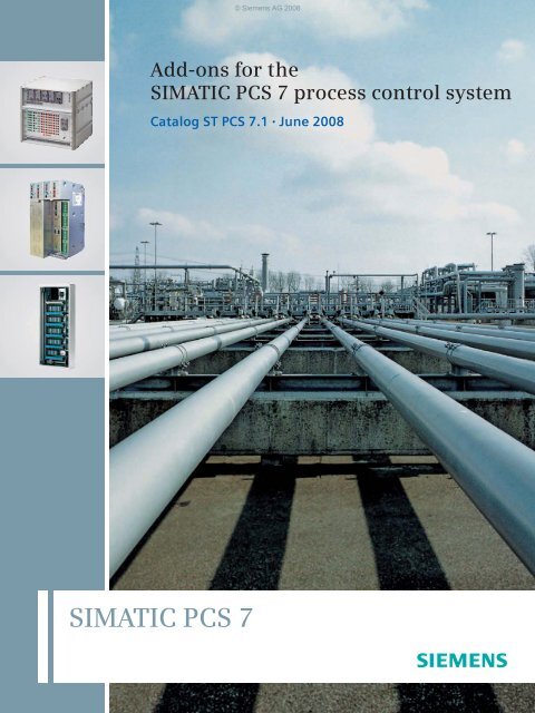
© <strong>Siemens</strong> AG 2008Add-ons for theSIMATIC PCS 7 process control systemCatalog ST PCS 7.1 • June 2008SIMATIC PCS 7
© <strong>Siemens</strong> AG 2008Related catalogsSIMATIC ST PCS 7SIMATIC PCS 7process control systemSITRAINTraining for Automation andIndustrial SolutionsITCE86060-K4678-A111-B3-7600E86060-K6850-A101-B8 1)SIMATIC ST PCS 7.2Migration solutions with theSIMATIC PCS 7process control systemE86060-K4678-A131-A3-7600SIMATIC ST 70Products forTotally Integrated Automationand Micro AutomationE86060-K4670-A101-B1-7600E86060-K4670-A151-A3-7600 (News)Catalog CA 01 CA 01The Offline Mallof Automation and DrivesE86060-D4001-A100-C7-7600 (CD-ROM)E86060-D4001-A500-C7-7600 (DVD)A&D MallInternet:www.siemens.de/automation/mallSIMATIC HMI ST 80Human Machine InterfaceSystems1)Available in German only.See your local <strong>Siemens</strong> representative for furtherinformationE86060-K4680-A101-B5-7600Industrial CommunicationIndustrial Communicationfor Automation and DrivesIK PIE86060-K6710-A101-B5-7600E86060-K6710-A121-A2-7600 (News)TELEPERM M PLT 112AS 488/TMAutomation SystemsOnly PDF (E86060-W3812-A100-A3-7600)Process Automation FI 01Field instruments forProcess AutomationE86060-K6201-A101-A9-7600
© <strong>Siemens</strong> AG 2008SIMATIC PCS 7Add-ons for the SIMATIC PCS 7process control systemCatalog ST PCS 7.1 · June 2008Introduction1Information and management systems2Advanced Process Control3Industry-specific applications4Operator control and monitoring5Libraries/blocks/tools6Distributed I/O on the PROFIBUS7Supersedes:Catalog ST PCS 7.1 · April 2007The products contained in this catalogcan also be found in the e-Catalog CA 01.Order No.:E86060-D4001-A100-C7-7600 (CD-ROM)E86060-D4001-A500-C7-7600 (DVD)Please contactyour local<strong>Siemens</strong> branch© <strong>Siemens</strong> AG 2008Simulation8Diagnostics9Laboratory automation10Cabinet construction11Time synchronization12Other13Appendix14
1/2 <strong>Siemens</strong> ST PCS 7.1 · June 2008© <strong>Siemens</strong> AG 2008
© <strong>Siemens</strong> AG 2008Add-ons for SIMATIC PCS 7As a process control system within the company-wideautomation concept Totally Integrated Automation (TIA),SIMATIC PCS 7 with its integrated data storage, communicationand configuration offers an open basis for modern,future-oriented and economical automation solutions inall sectors of the processing industry as well as in the productionand hybrid industries (combination of continuous/batch processes and discrete manufacture).In the TIA network, SIMATIC PCS 7 can notonly assume the usual process-controltasks, but can also automate secondary processes(e.g. filling, packaging) or incoming/outgoing goods logistics (e.g. materialfeeding, storage) for a production site.By connecting the automation level to theIT world, the process data is availablethroughout the company for the evaluation,planning, coordination and optimizationof operating sequences, productionand business processes.With its future-oriented design, modularand open architecture based on the latestSIMATIC technology, the consistent use ofindustrial standards and the control systemfunctionality combined with high performance,the SIMATIC PCS 7 process controlsystem permits the cost-effective implementationand economic operation of instrumentationand control systems in allphases and taking into account the followingaspects: from planning, engineering,commissioning, training, to maintenanceand repair, right up to expansion and retrofitting.The modularity, flexibility, scalability andopenness of SIMATIC PCS 7 offer idealconditions for integrating additionalcomponents and solutions into the processcontrol system and completing and extendingtheir functionality in this way.1/4 <strong>Siemens</strong> ST PCS 7.1 · June 2008
© <strong>Siemens</strong> AG 2008Since SIMATIC PCS 7 was launched on themarket, we at <strong>Siemens</strong> as well as our externalpartners have developed a host of supplementarycomponents that we refer to inshort as PCS 7 add-ons.PCS 7 add-on products are software packagesand hardware components that areoptimally tailored to the respective applicationand thus permit the cost-effective useof SIMATIC PCS 7 for special automationtasks.This catalog will make it easier for you tofind the right products for your specific solution.<strong>Siemens</strong> ST PCS 7.1 · June 20081/5
© <strong>Siemens</strong> AG 2008Information andManagement Systems2/2 PIMS-PCS 7-CONNECT:Combination of plant informationsystems and PCS 72/4 PCS 7 OCS:Open interface for connection ofthird-party applications2/6 PLSDOC RE:Documentation updating systemfor SIMATIC PCS 72/7 ACRON 7:Long-term archiving and loggingfor SIMATIC PCS 7<strong>Siemens</strong> ST PCS 7.1 · June 2008
© <strong>Siemens</strong> AG 2008Information and Management SystemsPIMS-PCS 7-CONNECT: Combination ofplant information systems and PCS 72■ OverviewPCS 7 Add-onfit for SIMATIC PCS 7 V7A plant information system (PIMS) is an information system forcompany/plant-independent short-term/long-term archiving andfor evaluation and display of process and production data.The products described here (interfaces and tools) supportcost-effective collaboration between SIMATIC PCS 7 includingSIMATIC BATCH and the plant information systems:• PI System from OSIsoft (PI-PCS 7-CONNECT)• aspenOne from AspenTech (aspenOne-PCS 7-CONNECT)The interfaces and tools for optimum combination of PI Systemand aspenOne with SIMATIC PCS 7 feature high flexibility, performanceand safety. They also support redundant systems andarchive recovery concepts, e.g. in the event of interferences in aconnection.We can additionally offer tailored, scalable support and servicesfor efficient implementation and maintenance of these interfacesand tools. Information on support and services as well as manufacturerdeclarations are available on request (for contactaddresses, see "Further information").■ FunctionPI-PCS 7-CONNECTPI-CONNECT @PCS 7 and PI-CONNECT OPC+ interfacesPI-CONNECT @PCS 7 and PI-CONNECT OPC+ read the processvariables cyclically from SIMATIC PCS 7 and save these inthe PI long-term archive. The PI-CONNECT @PCS 7 interfaceuses the following interfaces for communication with SIMATICPCS 7:• @PCS 7 system interface• PI-CONNECT OPC+ interface• OpenPCS 7 interface• OPC interfaceThe two interfaces are operated on a separate interface PC onthe OS-LAN (terminal bus) of the SIMATIC PCS 7 process controlsystem, and support:• Redundancy functionality of the SIMATIC PCS 7 OS server• Concurrent time stamp treatment• Archive recovery• Failover onlinePI-CONNECT @PCS 7 and PI-CONNECT OPC+ can be used togetherwith SIMATIC PCS 7 V5, V6 and V7.PI-CONNECT ALARM interfaceThe PI-CONNECT ALARM interface can be used to transfermessages from the SIMATIC PCS 7 process control systemand/or other sources to the PI archive. Since most of the requirementsand special features to be considered are project-specific,PI-CONNECT ALARM cannot be offered as a standardproduct but only as an individual solution based on the standardinterface.PI-CONNECT ALARM can be used together with SIMATIC PCS 7V5, V6 and V7.PI-CONNECT TREND toolProcess data from the PI archive can be output usingPI-CONNECT TREND as clear and informative trend viewsin SIMATIC PCS 7 OS process displays. Independent of theplant or plant section, you can then display additional informationconcerning the process (based on the PI long-term archives)directly on the operator system of the process controlsystem.PI-CONNECT TREND can be used together with SIMATIC PCS 7V5, V6 and V7.PI-CONNECT CONFIG toolPI-CONNECT CONFIG works together with PI CONNECT@PCS 7, PI-CONNECT OPC+ and the OPC interface of OSIsoft.The tool provides convenient support for creation and easy updatingof the PI system project for the SIMATIC PCS 7 link. It canbe used equally for initial configuration of the PI system and fortracking of SIMATIC PCS 7 configuration modifications in thePI system.PI-CONNECT CONFIG can be used together with SIMATICPCS 7 V5, V6 and V7.2/2 <strong>Siemens</strong> ST PCS 7.1 · June 2008
© <strong>Siemens</strong> AG 2008Information and Management SystemsPCS 7 OCS: Open interface for connection ofthird-party applications2■ OverviewPCS 7 Add-onExamples ofclient applicationsfit for SIMATIC PCS 7 V7INTERNETPCS 7 plant bus CS 275PCS 7ASMicrosoftExcelLANPCS 7 OCSOS serverPCS 7ASSystemBrowserPCS 7ASWebserverPCS 7 OCSPCS 7/TM-OS serverTELEPERM MASWeb BrowserSQLdatabaseCouplerProcess valuesProcess archivesMessage archivesTELEPERM MASMESPIMSSAPmodulesControl system,non-<strong>Siemens</strong>PCS 7 OCS is an open interface by means of which other applicationscan easily access data and data structures of SIMATICPCS 7 from a wide variety of application areas via a network. Theinterface is based on the open, platform-independent communicationsstandard ACPLT/KS. The data are transmitted by TCP/IPwithout using the Windows basic technologies COM and DCOM.In this manner it is possible to achieve extremely stable and firewall-compatiblecommunication throughout the network.Note:PCS 7 OCS can be used together with SIMATIC PCS 7 V5, V6 and V7.■ ApplicationUsing PCS 7 OCS you can link, for example, the following externalapplications to SIMATIC PCS 7:• Office applications such as Microsoft Excel, e.g. for automaticgeneration of reports• Simulation and optimization tools, e.g. for controller monitoringand optimization• Visualization software for cross-plant information presentations• Standard web browsers for online presentation of product information• External database applications, e.g. for cross-plant long-termarchiving• Plant information management systems (PIMS)• MES and ERP systems for production and corporate management• Process control systems from other manufacturers■ FunctionThe PCS 7 OCS is installed directly on the PCS 7 OS server orthe PCS 7/TM-OS server for TELEPERM M migration. Neither additionalhardware nor any special configuration of the respectiveOS server is necessary. In the case of redundant systems, PCS 7OCS must be installed on both OS servers of a server pair.Using PCS 7 OCS, the applications can read and write configurationand process variables and also read all process value archivesof the TagLogging and alarm logs of the AlarmLogging.Using inquiry functions it is additionally possible to search fordata objects with specific properties of the same type (e.g. typesof function block, parameter types, etc.). Since the interfacing isimplemented by autoconfiguration, the applications need not bespecifically configured for the interface connection.Standard client applicationsThe following standard client applications are available:• System browser KS Magellan ProUsing KS Magellan Pro it is possible to search and read thecomplete PCS 7 OCS database via Internet from a PC workstation.KS Magellan Pro is versatile in its application: for thefunction test during commissioning as well as for online queriesof process values, process archives and alarm logs duringoperation.• Database coupler KSHistBuilderThe KSHistBuilder can be used to cyclically transfer archivesor online data from SIMATIC PCS 7 to an SQL database. Noconfigurations are required to transfer archives. Existing archivesare automatically discovered, and transferred withoutgaps to the database, even if the communication fails briefly.In addition to trends, it is possible to read alarm logs and totransfer these to an open database or operating data acquisitionsystem.• Excel add-inUsing this Microsoft Excel expansion, it is possible to readprocess values, process archives and alarm logs fromSIMATIC PCS 7 manually or cyclically into Excel.• SAP couplingThe SAP coupling permits simple transfer of data fromSIMATIC PCS 7 to SAP. The SAP coupling can be used, for example,to continuously transfer runtime meter data and faultmessages to the SAP PlantMaintenance (PM) module. Furthermore,all other SAP modules can be coupled to SIMATICPCS 7.• Web server with dynamically generated HTML sitesThe web server is used to provide individually designed websites with up-to-date data directly from the process controlsystem.The PCS 7 OCS interface is exceptionally suitable for linking externalapplications to SIMATIC PCS 7 using autoconfigurationfunctions or simply to read data from the process control system.A PCS 7 OCS license allows use of the following functions:• Reading and writing all variables of an OS server• Reading process value archives and alarm logsData exchange between the OS server and the application is extremelypowerful. It is based on the TCP/IP communications protocol,an open standard supported by the vendors of many controlsystems.By omitting Windows communications technologies such asCOM/DCOM, PCS 7 OCS can also be used without problem indistributed networks connected through firewall functions. Noconfiguration operations are required to install PCS 7 OCS.2/4 <strong>Siemens</strong> ST PCS 7.1 · June 2008
© <strong>Siemens</strong> AG 2008Information and Management SystemsPCS 7 OCS: Open interface for connection ofthird-party applications■ Selection and Ordering DataSIMATIC PCS 7 OCS V2.3Open communication server forSIMATIC PCS 7 V5, V6 and V7Engineering software with a runtimelicense for one PCS 7OS serverKS Magellan ProOrder No.6DL5 405-8AD23-0XA0On request■ More informationLeiKon GmbHKaiserstr. 10052134 HerzogenrathGermanyPhone: +49 2407 95 17 330Fax: +49 2407 95 17 3392E-mail: contact@leikon.deAdditional information is available in the Internet under:http://www.leikon.de<strong>Siemens</strong> ST PCS 7.1 · June 20082/5
© <strong>Siemens</strong> AG 2008Information and Management SystemsPLSDOC RE: Documentation updating systemfor SIMATIC PCS 7■ Overview■ Function2PCS 7 Add-onfit for SIMATIC PCS 7 V7Application computer- PLSDOC ® RE front end- PLSDOC Tracker for scanning of OPCgateway, communication with database- Memory location PLSDOC ® RE- Memory location Support&Help foraccess of the OS OSsOperatorstationEngineeringstationPLSDOC ® REdatabaseTerminal bus:Industrial Ethernet100 Mbit/s,fiber-opticRedundantOS serverOSMOSMOPC gatewayMonitoring of OPC variables forchangesThe PLSDOC RE documentation updating system is provided fordocumentation of SIMATIC PCS 7 systems and for supportthroughout the complete lifecycle.System support engineers profit from the high availability of informationand are provided with support for quality assurance.PLSDOC RE matches the plant documentation to the currentdata of the process control system without delay, and recordsany changes in change logs.Information relevant to system support engineers is provided byPLSDOC RE in the form of standardized project documents, e.g.IB/FAT reports, measuring circuit test reports, quantity frameworks,repetition reports.System-specific configuration of PLSDOC RE is simple to carryout and is supported by a program wizard.Note:PLSDOC RE can be used together with SIMATIC PCS 7 V5, V6 and V7.■ Benefits• Standardized documentation of process objects• Fast and correct comparison of data in process control systemand feature specification: Changes to customized parametersare completely documented, e.g.: limit values, control parameters,measuring ranges, interlocking information• Provision of standardized documents for system configurationand support• Integration of feature specification into the operator systems→ information directly available for the support engineers• PLSDOC RE monitors redundant pairs of servers in the contextof documentation updating. Should a server fail, a switchis made to the redundant server.• The modification information is buffered between the OSserver and PLSDOC RE. This means that no modification informationis lost before PLSDOC RE can establish a connectionto the OS server.• PLSDOC RE generates HTML documents for every processvariable. These documents can be integrated into the processdisplays for direct calling.• References to other process variables are made by means ofhyperlinks, meaning that direct calling is possible.• Information on the system peripherals (computer, printer, softwarelicenses, etc.) can also be managed using PLSDOC RE.• The recording of information independent of process objectsis also possible, e.g. information on maintenance work andmeasures taken in the event of faults.■ Technical specificationsSystem requirementsApplication computer:Microsoft Windows NT4.0 SP6/2000/XP, 512 MB RAM, 100 MBhard disk, Acrobat Reader 5.0 or higher■ More informationFinze & WagnerEMSR-Ingenieurgesellschaft m.b.H.Elektro-Mess-Regel-Steuerungs-TechnikPiracherstraße 7684489 BurghausenGermanyPhone: +49 8677 884-725 (Mr. Fröhlich)E-mail:Support: support.plsdoc@fi-wa.comInformation: info.plsdoc@fi-wa.comAdditional information is available in the Internet under:http://www.fi-wa.com2/6 <strong>Siemens</strong> ST PCS 7.1 · June 2008
© <strong>Siemens</strong> AG 2008Information and Management SystemsACRON 7: Long-term archiving and loggingfor SIMATIC PCS 7■ Overview■ DesignPCS 7 Add-onfit for SIMATIC PCS 7 V7ConfigurationDesignerReporterACRON evaluationGraph Alert MaintenanceExternalevaluationOPCODBCMicrosoft Excel2DatabaseConfigurationProcessvaluesManualvaluesCompressedcalculateddataData recordingProcess 1Process 2ProviderSIMATIC PCS 7, OPC,ASCII, DDE, ODBC, etc.Process nACRON is a product for system optimization, long-term archivingand logging which supports you for compliance with verificationrequirements. It was originally designed for special requirementsin environmental technology, but has also provensuccessful in many different sectors for more than 12 years. Thehigh requirements encountered in the water/wastewater/environmentalsector (e.g. ATV M260 in Germany) can also be fulfilledwith ACRON.ACRON 7, the current version, offers an exceptional price/performanceratio, and is impressive in operation thanks to highavailability, running reliability and data integrity. Simple configuration,easy handling and high flexibility are further exceptionalfeatures.ACRON 7 is scalable from a small single-user system up to anetworked client/server system for large applications.The interfaces of ACRON 7 are matched to the SIMATIC PCS 7process control system. Certain modules can be integrated asOCX in SIMATIC PCS 7.ACRON 7 is currently available in English, German and Italian.Note:ACRON 7 can be used together with SIMATIC PCS 7 V6 and V7.The following modules are components of ACRON 7:• Database:Up to 100 000 data points, time-based or change-dependentrecording, arithmetic operations, high performance with resolutionin millisecond range, high data security due to TLC(Three Level Cache)• Provider:Data acquisition from any sources with telecontrol link• Reporter:Convenient operator interface for printing of reports and logswith input facility for laboratory values• Graph:User-friendly presentation and analysis of measured valuesand statistical values in trends• Fault and maintenance module:Generation of all required fault and message reports as well ascomprehensive statistics• AC Job:Administration module for automatic printing of reports includingsending by e-mail• Data Collect:Combination of any values from various ACRON applications• Excel Add-In:Convenient access to all data• AC Mirror:Up to 8-fold database redundancy■ More informationVIDEC GmbHOsterdeich 10828205 BremenGermanyPhone: +49 421 339500Fax: +49 421 3379561E-mail: info@acron7.comAdditional information is available in the Internet under:http://www.acron7.com■<strong>Siemens</strong> ST PCS 7.1 · June 20082/7
© <strong>Siemens</strong> AG 2008Information and Management Systems22/8 <strong>Siemens</strong> ST PCS 7.1 · June 2008
© <strong>Siemens</strong> AG 2008Advanced Process Control3/2 INCA:Model-predictive multi-variablecontroller3/3 Presto:Soft sensors for non-measurablequality variables3/4 RaPID:Expert tool for the optimization ofPID controllers3/5 ADCO:Adaptive controller3/6 MATLAB/SIMULINK-DDE client:Online coupling for APC3/7 FuzzyControl++:Configuration tool for fuzzy logic3/8 NeuroSystems:Configuration tool for neuralnetworks<strong>Siemens</strong> ST PCS 7.1 · June 2008
Advanced Process Control© <strong>Siemens</strong> AG 2008INCA: Model-predictive multi-variable controller3■ OverviewPCS 7 Add-onfit for SIMATIC PCS 7 V7INCAThis procedure is also used by INCA, a multi-variable controllerof the latest generation. INCA differs from classic MPC controllersdue a series of functional extensions. Modern modelingmethods, bumpless switching between different models (multimodelhandling), expansions for batch processes, non-linearpredictions, and a high quality of control are setting new standardsand enable plant-wide optimization as well as the controlof non-linear processes.The INCA (or GlassExpert) software itself runs on a separate PCunder the Windows NT/2000/XP operating system.Note:INCA can be used together with SIMATIC PCS 7 V5, V6 and V7.Multi-variable controller with integral optimization procedureCommon control concepts in the process industry today are stillalmost exclusively based on PID controllers and also includemanual intervention by the plant operator. In processes withcomplex dynamics, linked process variables or limitations, PIDcontrollers reach their limit.If a process is to be operated close to the capacity limit, while atthe same time minimizing waste and assuring the required quality,consideration of these precise boundary conditions in thecontroller strategy is absolutely essential.Additional weak spots are product or load changes which aregenerally carried out partly or completely by the plant operator.This causes variations which prevent optimum quality beingmaintained at all times.By carefully applying advanced modern control procedures(Advanced Process Control, APC), the process industry has realleverage available for reducing costs and increasing quality. Ofall the modern control procedures, Model Predictive Control(MPC) has emerged as the most suitable approach in numerousapplications. MPC simplifies the handling of complex plant dynamics,permits the early elimination of faults, takes into considerationthe plant limitations, and allows complex process controlstrategies.The use of Advanced Process Control extends SIMATIC PCS 7with the function of "process optimization". This creates a link betweenthe planning and scheduling functions of the executionlevel and the process control functions of the control level.■ ApplicationINCA for the glass industryPreconfigured solutions based on INCA are available speciallyfor the glass industry. The GlassExpert series currently comprises:• "TubingExpert"for dimensioning control of glass tubes• "ProfileExpert"for temperature profile control in glass channels• "MeltingExpert"for floor and atmosphere temperature control in glass meltingends.INCA for the chemical industry, application examples• Ammonia plants- Increase in throughput by up to 1%- Increase in steam export by up to 1%- Reduction in specific gas consumption by up to 1%- Increased plant availability- Less sensitive to changes in gas condition• Polymer plants- More flexible operation (faster change of product)- Production on request■ More informationIPCOSTel.: +32 1639 3083Fax: +32 1639 3080E-mail: info@ipcos.comAdditional information is available in the Internet under:http://www.ipcos.com3/2 <strong>Siemens</strong> ST PCS 7.1 · June 2008
© <strong>Siemens</strong> AG 2008Advanced Process ControlPresto: Soft sensorsfor non-measurable quality variables■ OverviewPCS 7 Add-onfit for SIMATIC PCS 7 V7The soft sensor predictions enable the frequency of laboratoryanalyses and the use of online analyzers to be reduced. Theyraise product quality while at the same time reducing operatingcosts.Presto is a tool for designing, parameterizing and operating softsensors. It makes it easier to master complex plant dynamics,and enables operating conditions to be optimized so that thequality of the end product is assured.Note:Presto can be used together with SIMATIC PCS 7 V5, V6 and V7.3■ ApplicationApplication examples• Polymer thickness• Polymer melt-flow index• Viscosity• Product concentration at the outlet of reaction or distillationcolumns• Plant efficiency/utilization factor• Gas concentrations (NO x , CO 2 , etc.)Presto sets new standards for the permanent plant-wide optimizationand control of non-linear processes. Presto differs fromOnline determination of quality variablesProduction plants in the process industry today rely on regular other soft-sensor program packages due to its series of functionand very time-consuming laboratory analyses for quality control expansions that support the designer when drafting reliable softpurposes (new measured values typically every 8 to 24 hours) - sensors:or they use very expensive, high-maintenance online analyzers • Modern modeling methods such as linear transmission functions,general non-linear models (GNOMOs) or estimates ac-(new values typically every 20 to 60 minutes). In order to raiseproductivity and run the process up to its full capacity while cording to the partial least squares estimators methodmaintaining the required quality, it is necessary to measure productquality online with a refresh rate of between 0.5 and• Signal processing or pre-processing (offline and online)3 minutes. This ensures that the controller responds at the right • Powerful tools for selecting suitable input variablestime and the product specifications are maintained.• Input options for data from laboratories and analyzersThe weaknesses of previous designs for process control are also Soft sensors are a prerequisite for plant optimization and qualityreflected in the changes of product quality or production capacitywhich, as a rule, are performed partly or completely by thecontrol using advanced process control solutions such as INCA.The Presto program package can run on standard PCs with theplant operator. This results in longer periods in which the productionspecifications do not comply with the quality require-Windows 2000/XP operating system. It is linked to the SIMATICPCS 7 process control system by means of OPC, where Prestoments, as no quality values are known while the changes are beingmade.is operated as an OPC client.These problems can be solved by using soft sensors. Soft sensorsare calculation procedures which determine non-measur-■ More informationable quality variables on the basis of measurable process values IPCOS(pressures, flow rates, temperatures, levels, etc.) in cycles of between0.5 and 3 minutes. The calculation is made on the basisPhone: +32 1639 3083of a (non-)linear parametric model generated from historic plantFax: +32 1639 3080data or through dedicated tests. The high-speed soft sensor E-mail: info@ipcos.compredictions can be consolidated by laboratory analyses or valuesfrom online analyzers.Additional information is available in the Internet under:http://www.ipcos.comProcess variablesTemperaturesPressuresLevelsFlow rates(every 0.5 ... 3 min)Quality variablesDensitiesConcentrationMelt IndexesViscosities(every 8 ... 24 hrs)from laboratoryNon-linearparametric modelPRESTO Soft SensorConsolidation/compensationand updatingQuality variablesDensitiesConcentrationMelt-flow indicesViscosities(every 0.5 ... 3 min)from PRESTOTo the closed-loopcontrol system<strong>Siemens</strong> ST PCS 7.1 · June 20083/3
Advanced Process Control© <strong>Siemens</strong> AG 2008RaPID: Expert toolfor the optimization of PID controllers■ Overview■ FunctionRaPID differs from other controller setting packages as follows:• Optimization of PID control loops on the basis of engineeringspecifications• Controller setting for optimum compensation of disturbances• Controller setting for optimum command behavior with predefinedsetpoint changesData acquisitionCollection of process data by means of an online OPC connectionto the SIMATIC PCS 7 operator system or from offline files.Many test signals are available for initiating the process, including:• Setpoint step-change• Manipulated variable step-change• Ramps• Pseudo-disturbance binary signalsData preprocessingThe user can select and filter data to refine the results of the processidentification.System identificationA dynamic process model is defined on the basis of the collectedprocess data. Various model structures can be used:with/without dead time and different system arrangements.Users have the option of influencing the system identification onthe basis of their knowledge about the process. They can saveand compare the resulting process models.Controller designOn the basis of the chosen process model, controller parametersare determined for a certain specification. Consequently,the controller can be designed for optimum command behavior,optimum noise suppression or a combination of both.Simulation of the designed controllerAn evaluation of the control loop behavior is possible by simulationwithin RaPID, or online via the existing OPC connection. Thesimulation results obtained with different controller settings canbe saved and compared.Good settings for primary control loops are a prerequisite forsubsequent plant optimization, e.g. using INCA.3PCS 7 Add-onfit for SIMATIC PCS 7 V7The PCS 7 PID Tuner is offered as an option for the CFC Editorand enables you to determine the optimum controller parametersin predefined steps for PID, PI and P controls in a controlloop.The PCS 7 PID Tuner can be used for the software controllersCTRL_PID and CTRL_S. The RaPID program package, on theother hand, is a controller-independent and manufacturer-independenttool for fast and user-friendly, computer-aided optimizationof complex PID controllers. RaPID can run on standard PCswith the Windows NT/2000/XP operating system. It is linked tothe SIMATIC PCS 7 process control system by means of OPC.As an alternative to online data, files containing data collectedearlier can also be evaluated offline. The program package iscapable of processing the file formats of Microsoft Access, MicrosoftExcel, MATLAB and INCATest, as well as all types ofASCII files. RaPID contains predefined PID controller structuresfor PID controller types from SIMATIC PCS 7 and other manufacturers.With the aid of a dynamic process model, the user candetermine the optimum controller setting step by step.Note:RaPID can be used together with SIMATIC PCS 7 V5, V6 and V7.■ More informationIPCOSTel.: +32 1639 3083Fax: +32 1639 3080E-mail: info@ipcos.comAdditional information is available in the Internet under:http://www.ipcos.com3/4 <strong>Siemens</strong> ST PCS 7.1 · June 2008
© <strong>Siemens</strong> AG 2008Advanced Process ControlADCO: Adaptive controller■ OverviewPCS 7 Add-onfit for SIMATIC PCS 7 V7In practice, conventional PID controllers are often operated inthe manual mode because the control quality achieved does notmatch the expectations. The reason for this is that the controllersare either badly adjusted or the processes are difficult to controlwith PID controllers, e.g. temperature systems, processes withany proportion of dead time component, or processes thatchange depending on time or operating point. In addition, theoptimum setting of PID controllers demands special experienceand is very time-consuming.A recommended alternative for solving these problems is theadaptive ADCO controller. It works on the basis of a processmodel that is determined in the background during the settingprocedure. With the aid of this process model, ADCO can predictthe consequences of an intervention in the process (predictivecontroller), e.g. what effect the opening of a steam valve upto a certain extent has on the process temperature. Conversely,it is also in a position to determine the valve setting required forachieving or maintaining a defined temperature. With the processmodel, ADCO has more process information at its disposalthan conventional controllers and uses this to improve the qualityof control.Multi-range controller for non-linear systemsADCO is also available as a multi-range controller (ADMR). Thespecial feature of this type of controller is that the control rangecan be divided into as many as 8 zones which can be individuallyoptimized. The switchover between the zones can be automaticor event-based.■ ApplicationThe adaptive controller ADCO can be used as a better alternativeto the conventional PID controller, in particular for processesthat are difficult to control. This has the following advantages:• About 10 to 20% time savings in the commissioning phasedue to the fast and rugged controller setting• Significantly better control quality for difficult processes• Very good adaptability, especially where there are changes tothe process characteristics• Significant reductions in transmission times in the case of statustransitions in batch processes (e.g. heating a product fromtemperature level A to level B)Note:The adaptive controller ADCO can be used together with SIMATIC PCS 7V5, V6 and V7.■ Technical specificationsADCOHardware requirementsMemory requirementComputing time■ More informationi.p.a.s.-systemeAn der Landwehr 660437 FrankfurtGermanyPhone: +49 69 950418-0Fax: +49 69 950418-19E-mail: service@ipas-systeme.deSIMATIC PCS 7 V5.x or higherwith AS 41x automation systems21 KB (once only)+ 5 KB (per controller)Approx. 2 ms (S7-416)Additional information is available in the Internet under:http://www.ipas-systeme.de3ADCO faceplate with detail area for alarm limits / batch<strong>Siemens</strong> ST PCS 7.1 · June 20083/5
Advanced Process Control© <strong>Siemens</strong> AG 2008MATLAB/SIMULINK-DDE client:Online coupling for APC3■ OverviewPCS 7 Add-onControllerstructureadde.medde.mTriggerMATLAB/SIMULINKfit for SIMATIC PCS 7 V7DDEPC SIMATIC PCS 7OSControlsystemstructureMATLAB/SIMULINK is a universal mathematical software toolwith a host of functions for control engineering, information processing,model creation, optimization, and data analysis. It is themost widely used software tool for the development of high-qualityAdvanced Process Control (APC) algorithms.The MATLAB/SIMULINK-DDE client can be used for implementingthe APC algorithms, which are tested in an offline simulation,in the real-time operation on the process. It permits real-time capableonline linking of MATLAB/SIMULINK to any DDE serverand thus "rapid prototyping" of automation functions with the entirestock of MATLAB libraries. As the algorithm developed inMATLAB does not have to be implemented again, the potentialerrors of a re-implementation and the associated engineeringtime and costs can be saved in Advanced Process Controlprojects.Note:The MATLAB/SIMULINK-DDE client can be used together with SIMATICPCS 7 V5, V6 and V7.-1XRealprocess■ ApplicationVia a DDE channel, MATLAB/SIMULINK can gain read and writeaccess to all variables declared in the operator system of theSIMATIC PCS 7 process control system (DDE server).MATLAB/SIMULINK and the MATLAB/SIMULINK-DDE client canbe installed either on an operator station or an additional PC.Communication is initialized and controlled by the DDE client.Typical procedures in developing Advanced Process Control solutions:• Offline analysis of the problem to be solved, also including theanalysis of measured process data in MATLAB/SIMULINK• Offline synthesis of possible solutions withMATLAB/SIMULINK• Offline test by simulation of the solutions withMATLAB/SIMULINK• Configuration of the link on the SIMATIC PCS 7 process controlsystem, parameterization of the DDE server• Configuration of possible back-up functions in the processcontrol system• Connection of MATLAB/SIMULINK to the process control system• Test and optimization of the solution on the process• If required, transfer of tried and tested functions into functionblocks that can be integrated into the process control system■ FunctionThe MATLAB/SIMULINK-DDE client comprises three blocks:Trigger blockThe trigger block enables the user to specify the DDE communicationpeer, the data format and the sampling time. It synchronizesand monitors the communication and issues warnings ifthe DDE channel is defective or interrupted.Input and output block (Edde/Adde)The "Adde" block writes data from MATLAB to the DDE server.Each block can manage up to four variables, and several blocksare possible. The "Edde" block reads variables into MATLAB andconverts them into the corresponding format.MATLAB/SIMULINK-DDE client• Link to any SIMATIC systems by means of a PCS 7 operatorstation and the associated DDE server, or directly via theSIMATIC NET OLE/DDE Manager• Link to older control systems, e.g. TELEPERM M viaWinTM/Server• Link to any DDE server■ Selection and Ordering DataMATLAB/SIMULINK-DDE clientfor SIMATIC PCS 7 V5, V6 and V7Order No.2XV9 450-1WC12-0LA0 C)C) Subject to export regulations: AL: N, ECCN: EAR99S■ More information<strong>Siemens</strong> AGIndustry SectorErlangenPhone: +49 91 31 7-461 11Fax: +49 91 31 7-447 57E-mail: it4industry@siemens.com3/6 <strong>Siemens</strong> ST PCS 7.1 · June 2008
© <strong>Siemens</strong> AG 2008Advanced Process Control■ OverviewPCS 7 Add-onfit for SIMATIC PCS 7 V7FuzzyControl++:Configuration tool for fuzzy logicThe configuration tool is used to configure and generate thefuzzy systems. During operation, the runtime software then executesthe systems which are present in a data block in the caseof SIMATIC PCS 7.FuzzyControl++ is a <strong>Siemens</strong> configuration tool for fuzzy logic. Itoffers solutions for non-linear controllers and for predicting thebehavior of complex mathematical procedures from process automationwhich are difficult or impossible to implement usingstandard tools.FuzzyControl++ enables fuzzy systems to be developed andconfigured effectively for the automation of technical processes.Empirical process knowledge and verbally described experiencecan be implemented directly in open-loop and closed-loopcontrols, pattern recognition, decision logic, etc.Note:FuzzyControl++ can be used together with SIMATIC PCS 7 V5, V6 andV7.■ Selection and Ordering Data Order No.FuzzyControl++ for SIMATIC PCS 7 V7 (V7.0 + SP1 and higher)FuzzyControl++ D+E basic 2XV9 450-1WC10-0AA1 C)licenseConfiguration tool running underWindows 2000 and XP, MPIlicense, S7 blocks for one application,manual, German andEnglishFuzzyControl++ PCS 7 package 2XV9 450-1WC10-0PA0 C)CFC runtime module with faceplates,SIMATIC PCS 7 V7.0 +SP1 and higherFuzzyControl++ S7 and CFC 2XV9 450-1WC11-4XA0 C)copying license for further datablocksFuzzyControl++ for SIMATIC PCS 7 V5 and V6FuzzyControl++ D+E basiclicenseConfiguration tool running underWindows 2000 and XP, MPIlicense, S7 blocks for one application,manual, German andEnglish2XV9 450-1WC10-0AA1 C)FuzzyControl++ communicationspackagefor loading the blocks and onlinemonitoring via the PCS 7 IndustrialEthernet plant busFuzzyControl++ CFC packagewith blocks and faceplate forPCS 7 V5 and V6FuzzyControl++ S7 and CFCcopying license for further datablocks2XV9 450-1WC10-0DA0 C)2XV9 450-1WC10-0EA0 C)2XV9 450-1WC11-4XA0 C)3C) Subject to export regulations: AL: N, ECCN: EAR99S■ ApplicationTypical applications for fuzzy logic are:• Open-loop and closed-loop control■ More information• Parameter adaptation of controllers<strong>Siemens</strong> AG• Fault compensation and precontrolIndustry Sector• Pattern recognition, process data evaluation and diagnosis Erlangen• Automation of manual process interventions of a plant operatorFax: +49 91 31 7-447 57Phone: +49 91 31 7-461 11• Process control with coordination of subordinate open-loopE-mail: it4industry@siemens.comand closed-loop controllersExamples include pressure, temperature and level controls, aswell as control of speed and intervals. In early-warning and diagnosticsunits, fuzzy logic is used for the early detection ofAdditional information is available in the Internet under:http://www.siemens.com/fuzzycontrolhazardous states and for the implementation of decision-makinglogic.■ FunctionThe FuzzyControl++ configuration tool supports users when creatinga fuzzy system. The application of this tool requires onlybasic knowledge about such systems, as no mathematical orcontrol settings have to be made. Users are supported duringthe configuration process by extensive online help.The configuration tool package comprises:• Configuration tool (executes on the Windows 2000 andWindows XP operating systems)• Runtime software for SIMATIC PCS 7 (function block for CFCand OS faceplate).<strong>Siemens</strong> ST PCS 7.1 · June 20083/7
Advanced Process Control© <strong>Siemens</strong> AG 2008NeuroSystems:Configuration tool for neural networks■ Overview■ BenefitsThere are many good reasons for using NeuroSystems:• Artificial neural networks have now become the most frequentlyapplied approach for black box modeling of technical,chemical and biological systems.• As a result of the complex non-linear response of neural networks,processes can be simulated without exact knowledgeof the existing relationships and conditions.• The capability to learn and adapt, the fault tolerance, and theability to process inexact or even contradictory information areparticularly distinctive.• NeuroSystems is exceptionally well suited to prediction, optimization,classification, identification and closed-loop controltasks.• Neural networks created using NeuroSystems can be integratedwithout problem into an automation environment by usingruntime modules.• The neural networks execute completely in SIMATIC PCS 7.• Applications based on neural networks allow increases in performance,quality, productivity and efficiency, and save personneland time.3PCS 7 Add-onfit for SIMATIC PCS 7 V7During the automation of technical processes, especially theiroptimization, unconventional procedures and approaches withartificial intelligence are being increasingly used in addition totraditional methods. Neural networks are frequently applied insuch cases, and these have already proven their performancecapability in many applications. Notable successes could beachieved using them, even for tasks where conventional optimizationprocedures have failed.In contrast to classic technical systems with a powerful centralunit, a neural network consists of a complex interconnection ofmany simple processing units, so-called neurons. The architecturecopies the structure of the biological nervous system.Neural networks are flexible, are capable of learning, and canorganize themselves. Their parallel structure additionally resultsin very fast operation.Systems which are capable of learning can be generated bycombining neural networks with fuzzy logic, and the strengths ofthe two procedures are combined. This opens up many newpossibilities for automation technology.The NeuroSystems configuration tool from <strong>Siemens</strong> permits thegeneration of artificial neural networks for non-linear controlsand complex mathematical sequences in process automationand which cannot be implemented using conventional meansand methods, or only at great effort.NeuroSystems can be used to develop and train neural networksfor complex control tasks, virtual sensors, predictions, identifications,classifications, etc. simply and effectively even withoutspecial know-how. This results in blocks executable in SIMATICPCS 7 which can be integrated into the automation structure bylinking in the CFC.Note:NeuroSystems can be used together with SIMATIC PCS 7 V7.■ ApplicationTypical applications for neural networks include:• Complex closed-loop controls• Virtual sensors• Predictions• Identifications• Pattern recognition• Diagnostics and evaluation of process dataThe process industry - in particular the chemical industry - andthe production industry are the main fields of application for neuralnetworks. Quality control is one of the focal points for all sectors.■ FunctionThe NeuroSystems configuration tool supports users in the creationof neural networks. Configuration with NeuroSystems doesnot require any mathematical or control technology settings. Basicknowledge on such systems is sufficient.NeuroSystems includes functions for data analysis as well as forcomprehensive test and validation tasks. When working with thesystem, configuration engineers have access to comprehensiveonline help.The NeuroSystems configuration system comprises:• Configuration tool (executes on the engineering station withthe Windows 2000 and Windows XP operating systems)• Runtime software for SIMATIC PCS 7 (function block for CFCand OS faceplate).The configuration tool is used to configure and generate the neuralnetworks. During operation, the runtime software then executesthe neural networks which are present in a data block inthe case of SIMATIC PCS 7.3/8 <strong>Siemens</strong> ST PCS 7.1 · June 2008
© <strong>Siemens</strong> AG 2008Advanced Process ControlNeuroSystems:Configuration tool for neural networks■ Selection and Ordering Data Order No.NeuroSystems for SIMATIC PCS 7 V7 (V7.0 + SP1 and higher)NeuroSystems D+E basic 2XV9 450-1WC15-0AA0 C)license V5.1Configuration tool for creatingand testing neural networks underWindows 2000 and XP, two languages(German, English),including online help and manualas well as runtime module forSIMATIC S7, MPI registration fordownloading the blocks and foronline monitoring over MPI, S7blocks (FBs) for one applicationNeuroSystems SIMATIC PCS 7packageCFC runtime module with faceplatesfor one application,SIMATIC PCS 7 V7.0 + SP1 andhigher2XV9 450-1WC15-0PA0 C)■ More information<strong>Siemens</strong> AGIndustry SectorErlangenPhone: +49 91 31 7-461 11Fax: +49 91 31 7-447 57E-mail: it4industry@siemens.comAdditional information is available in the Internet under:http://www.siemens.com/neurosystems■3NeuroSystems S7 and CFCcopy license for furtherSIMATIC PCS 7/S7 applications2XV9 450-1WC16-4XA0 C)C) Subject to export regulations: AL: N, ECCN: EAR99S<strong>Siemens</strong> ST PCS 7.1 · June 20083/9
Advanced Process Control© <strong>Siemens</strong> AG 200833/10 <strong>Siemens</strong> ST PCS 7.1 · June 2008
© <strong>Siemens</strong> AG 2008Industry-specific applications4/2 Cement industry4/2 CEMAT:Software for the cement industry4/5 ECS/CemScanner:Monitoring of temperature in kiln jacket4/6 ECS/ProcessExpert:Specialized for process optimization4/7 Telecontrol4/7 SIMATIC PCS 7 TeleControl:Integration of widely distributedoutstations4/10 PCS 7 TeleControl EngineeringStation4/11 PCS 7 TeleControl Operator System4/13 SIPLUS RIC Compact:Modular telecontrol outstations4/17 SIPLUS RIC IEC on S7:AS coupling to a host control center4/20 SINAUT ST7:Telecontrol system based onSIMATIC S7<strong>Siemens</strong> ST PCS 7.1 · June 2008
Industry-specific applicationsCement industryCEMAT: Software for the cement industry© <strong>Siemens</strong> AG 2008■ Overview■ FunctionPCS 7 Add-onfit for SIMATIC PCS 7 V74CEMAT is a process control system that was designed for thespecial requirements in the cement industry and has provedsuccessful in many years of use worldwide in the tough environmentalconditions of cement works.The current system platform for CEMAT is the SIMATIC PCS 7process control system whose modern architecture offers theideal basis for future-proof and economical solutions in thecement industry. CEMAT uses the basic functionality, the opensystem interfaces, the flexibility and the scalability of SIMATICPCS 7 and optimizes the operating philosophy as well as thediagnostic, signaling and interlocking concept with industryspecificsoftware packages for the special tasks in lime and cementworks. This industry software has been developed in closecollaboration with the cement manufacturers and is the productof over 35 years experience in the cement industry.The functionality for the cement industry supplied in the form ofthe CEMAT software packages is integrated into the systemstructure of the SIMATIC PCS 7 basic system during the installation,and can be classified as follows:• Engineering components with function block libraries speciallytailored to the cement industry• Automation components for open-loop/closed-loop controlwith communications components for the controller connection• HMI components with:- Redundancy and archiving functions- Library for all control system objects with information, diagnosticand multimedia dialogs- Alarm system with industry-specific service functions- Diagnostic system for fast recognition of faults and reductionof downtimes• Web-compatible visualization of process displays and faceplates• Management information: listing and statistics functions aswell as long-term archiving• Technological interfaces for linking technological add-onmodules which are not part of the CEMAT product spectrum(also products from other manufacturers).It is especially worth noting the extensive multimedia support,e.g. by means of:• Video sequences for operating and service personnel• Showing of pictures in process screens• Integration of AutoCAD drawings (dxf)• Integration of plant plans• Context-sensitive provision of information depending on placeand timeNotes on deliveryCEMAT can be supplied in two versions:• CEMAT V7.0 (current version; for new plants), can be used onsystem platform SIMATIC PCS 7 V7.0• CEMAT V6.1 (alternative, particularly for plant expansions),can be used on system platform SIMATIC PCS 7 V6.1SIMATIC PCS 7 is not supplied with CEMAT, but must be orderedseparately (see Catalog ST PCS 7).4/2 <strong>Siemens</strong> ST PCS 7.1 · June 2008
© <strong>Siemens</strong> AG 2008Industry-specific applicationsCement industryCEMAT: Software for the cement industry■ Selection and Ordering DataCEMAT V7.0 software packagesCEMAT engineering softwareOrder No.CEMAT OSENG V7.06DL5 436-8AX07-0XA0Engineering software, 2 languages(German, English), executeswith Windows Server2003/XP Professional, SingleLicense for 1 installationType of delivery: software anddocumentation on CD, licensekey disk, Certificate of LicenseCEMAT OS software for single station incl. AS runtime licenses (PLC)CEMAT OSRT3 V7.0 (3 AS) 6DL5 434-8AA07-0XA0OS software Single Station Runtimeincl. 3 runtime licenses forAS (PLC), 2 languages (German,English), executes with WindowsServer 2003/XP Professional, SingleLicense for 1 installationType of delivery: software anddocumentation on CD, licensekey disk, Certificates of LicenseCEMAT OSRT6 V7.0 (6 AS) 6DL5 434-8AB07-0XA0OS software Single Station Runtimeincl. 6 runtime licenses forAS (PLC), 2 languages (German,English), executes with WindowsServer 2003/XP Professional, SingleLicense for 1 installationType of delivery: software anddocumentation on CD, licensekey disk, Certificates of LicenseCEMAT OS software for single station incl. AS runtime licenses (PLC)CEMAT MC V7.06DL5 435-8AX07-0XA0OS software Client Runtime, 2 languages(German, English), executeswith Windows XPProfessional, Single License for1 installationType of delivery: software anddocumentation on CD, licensekey disk, Certificate of LicenseCEMAT OS software for redundant pair of servers incl. AS runtimelicenses (PLC)CEMAT RSRT3 V7.0 (3 AS) 6DL5 433-8AA07-0XA0OS software Runtime for redundantpair of servers incl. runtimelicenses for 3 AS (PLC), 2 languages(German, English), executeswith Windows Server 2003,Single License for 2 installationsType of delivery: software anddocumentation on CD, licensekey disk, Certificates of LicenseCEMAT RSRT6 V7.0 (6 AS) 6DL5 433-8AB07-0XA0OS software Runtime for redundantpair of servers incl. runtimelicenses for 6 AS (PLC), 2 languages(German, English), executeswith Windows Server 2003,Single License for 2 installationsType of delivery: software anddocumentation on CD, licensekey disk, Certificates of License■ Selection and Ordering Data Order No.CEMAT RSRT9 V7.0 (9 AS) 6DL5 433-8AC07-0XA0OS software Runtime for redundantpair of servers incl. runtimelicenses for 9 AS (PLC), 2 languages(German, English), executeswith Windows Server 2003,Single License for 2 installationsType of delivery: software anddocumentation on CD, licensekey disk, Certificates of LicenseCEMAT RSRTU V7.0 (unlimited 6DL5 433-8AD07-0XA0AS)OS software Runtime for redundantpair of servers incl. runtimelicenses for unlimited AS (PLC),2 languages (German, English),executes with Windows Server2003, Single License for2 installationsType of delivery: software anddocumentation on CD, licensekey disk, Certificates of LicenseCEMAT OS PowerPacks for redundant pair of serversCEMAT OS PowerPack V7.0 forredundant pair of serversfor expansion of the AS runtimelicenses2 languages (German, English),executes with Windows Server2003, Single License for2 installationsType of supply: license key disk,Certificate of License• CEMAT PRSRT6 V7.0 for expansionfrom 3 to 6 AS6DL5 433-8AB07-0XD0• CEMAT PRSRT9 V7.0 for expansionfrom 6 to 9 AS6DL5 433-8AC07-0XD0• CEMAT PRSRTU V7.0 for expansionfrom 9 to unlimited AS6DL5 433-8AD07-0XD0CEMAT V7.0 bundlesCEMAT BOX 416 Runtime SystemV7.0 (3 AS)6DL5 438-1AA D)Bundle, comprising:• SIMATIC PCS 7 BOX 416Runtime System (AS/OS)• CEMAT OSRT3 V7.0 (3 AS)D) Subject to export regulations: AL: N, ECCN: 5D992B14<strong>Siemens</strong> ST PCS 7.1 · June 20084/3
Industry-specific applicationsCement industryCEMAT: Software for the cement industry© <strong>Siemens</strong> AG 20084■ Selection and Ordering Data Order No.CEMAT V6.1 software packagesCEMAT engineering softwareCEMAT OSENG V6.16DL5 436-8AX16-0XA0Engineering software, 2 languages(German, English), executeswith Windows 2000Professional/XP Professional, SingleLicense for 1 installationType of delivery: software anddocumentation on CD, licensekey disk, Certificate of LicenseCEMAT OS software for single station incl. AS runtime licenses (PLC)CEMAT OSRT3 V6.1 (3 AS) 6DL5 434-8AA16-0XA0OS software Single Station Runtimeincl. 3 runtime licenses forAS (PLC), 2 languages (German,English), executes with Windows2000 Professional/XP Professional,Single License for1 installationType of delivery: software anddocumentation on CD, licensekey disk, Certificates of LicenseCEMAT OS software for clientCEMAT MC V6.16DL5 435-8AX16-0XA0OS software Client Runtime, 2 languages(German, English), executeswith Windows 2000Professional/XP Professional, SingleLicense for 1 installationType of delivery: software anddocumentation on CD, licensekey disk, Certificate of License■ More information<strong>Siemens</strong> AGIndustry SectorErlangenFax: +49 9131 18-3444E-mail: cemat@siemens.comAdditional information is available in the Internet under:http://www.siemens.com/cemat4/4 <strong>Siemens</strong> ST PCS 7.1 · June 2008
© <strong>Siemens</strong> AG 2008Industry-specific applicationsCement industryECS/CemScanner:Monitoring of temperature in kiln jacket■ Overview4Correct measurement of the temperature on the jacket of a rotarykiln is important for efficient operation of processes carried outin cement and lime kilns. ECS/CemScanner represents state-ofthe-arttechnology in infrared scanning systems for kiln shells.The system combines a rugged design with advanced softwarefunctions, and is an indispensable aid for kiln operation and optimization.Note:ECS/CemScanner can be used together with SIMATIC PCS 7 V5 and V6.■ BenefitsAdvantages through application of ECS/CemScanner:7 Increased availability of kiln7 Reduced consumption of refractories7 Fewer downtimes7 Reduced heat consumption7 Overhauls can be plannedAs the first supplier of computer-based scanner systems for thecement industry, FLSmidth Automation has comprehensive experiencegained from more than 600 successful system installationsworldwide.The further development of the ECS/CemScanner is characterizedby two key terms: Precision and quality. The system usesa highly precise calculation algorithm to process the measuredvalues delivered by the high-quality scanner probe. Since thescanner probe can be positioned outside the kiln axis for practicalreasons (possibly even on the preheating tower), the softwaretakes into account the actual plant geometry in order to optimizethe precision of the temperature profile. A complete imageof the temperature on the kiln jacket is produced during just one■ More informationrevolution. The measuring point is usually smaller than one brick.FLSmidth Automation■ ApplicationPhone: +45 3618 2700Fax: +45 3618 2799The design of the scanner equipment is appropriate for the mostharsh environmental conditions, and ensures long-term andfault-free operation with a good measuring performance. Thescanner is accommodated in a stainless-steel protective housingand equipped with an air filter.Special features of the ECS/CemScanner system:• Refractory control:Graphic display and management of lining for kiln maintenance• Brick thickness:Online calculation and graphic display of brick and liningthickness• Live ring migration:Exact calculation and online monitoring of distance betweenring and kiln jacket• Fan control:Automatic starting/stopping of cooling fans underneath thekiln burning zone• PyroScan:Support of seamless integration of pyrometer measurementsin areas which cannot be reached by the scannerSoftware features of the ECS/CemScanner system:• Thermal profile with different statistical values• Display of kiln cross-section• Thermal 3D display of kiln from any position• 360° 3D display of kiln interior• 2D or 3D zoom• Animated playback of recorded data• Delta mode (comparison of two display profiles)• Customized range of colors• Configurable online monitoring of scanner hardware state• Data exchange with the CEMAT system based on SIMATICPCS 7• Operator interface in all important languagesE-mail: flsa@flsautomation.comAdditional information is available in the Internet under:http://www.flsautomation.com<strong>Siemens</strong> ST PCS 7.1 · June 20084/5
Industry-specific applicationsCement industryECS/ProcessExpert:Specialized for process optimization© <strong>Siemens</strong> AG 20084■ OverviewECS/ProcessExpert is specialized in powerful control and optimizationsolutions for complex processes such as e.g. pyro.ECS/ProcessExpert exhibits enhanced control and optimizationcapabilities tailored to fulfill individual user requirements.Various dedicated applications are available on theECS/ProcessExpert platform, e.g.:• Kiln and cooler applications for cement and lime processes• Application for ball and cement mills• Online determination of degree of fineness in cement mills• Online determination of free lime and NO x in pyro processes• Application for SAG mills in mining applicationsNote:ECS/ProcessExpert can be used together with SIMATIC PCS 7 V5 andV6.■ DesignOpen APC toolboxECS/ProcessExpert is an open toolbox for the development ofadvanced process control (APC) applications.The toolbox is an object-oriented environment with a number ofpredefined objects for fast prototyping of applications and controlstrategies. For the previously mentioned dedicated applications,process engineers have complete access to the engineeringmodule of ECS/ProcessExpert. This enables further updatingand adaptation of the optimization solutions.Depending on the type of application, advanced expert systemtechnologies are used in the ECS/ProcessExpert applicationmodules in order to implement hybrid automation concepts, e.g.• Fuzzy logic• Neural networks• Statistical process control (SPC)• Model-based predictive control (MPC)The application modules continuously analyze the process conditionsusing complex evaluations. They can execute appropriatecontrol measures more frequently and reliably than operatingpersonnel.As an open toolbox, ECS/ProcessExpert permits adaptation ofthe implemented solutions to the specific requirements of eachplant with optimum control know-how. As an integrated environment,the system offers an easy to use and open interface to theMATLAB software package for advanced implementations bythe user.ECS/ProcessExpert has an OPC interface for comprehensivedata exchange and integration into the CEMAT system based onSIMATIC PCS 7.■ More information■ BenefitsFLSmidth AutomationECS/ProcessExpert applications profit from more than two decadesof experience in the process industry, especially in the ce-Phone: +45 3618 2700Fax: +45 3618 2799ment industry. They feature the following advantages:7 Uniform process sequence, with significantly reduced maintenancecosts as a resultAdditional information is available in the Internet under:E-mail: flsa@flsautomation.com7 Reduction in production costs, e.g. in the costs for energy andhttp://www.flsautomation.comheat7 Fewer quality variations in final product7 Increase in production as result of improved process stabilityand availability4/6 <strong>Siemens</strong> ST PCS 7.1 · June 2008
■ OverviewPCS 7 Add-onfit for SIMATIC PCS 7 V7With many SIMATIC PCS 7 projects, especially in the water &wastewater and oil & gas industries, the high requirementsplaced on local automation are supplemented by the necessityto integrate the automation of widely distributed plant sectionsinto the process control system using telecontrol protocols.As far as the scope and performance of the automation functionsare concerned, the requirements of the widely distributedplant sections are usually in the bottom to mid range, meaningthat small automation stations can be used. SIMATIC PCS 7TeleControl particularly supports the following outstations:• SINAUT ST7 on the basis of SIMATIC S7-300/S7-400• SIPLUS RIC (Remote Interface Controller)These two types are presented separately in other sections ofthis catalog.Note:SIMATIC PCS 7 TeleControl can be used together with SIMATIC PCS 7V7.■ BenefitsAs a result of its high level of integration, automation based onSIMATIC PCS 7 offers decisive advantages compared to previousautomation solutions with telecontrol engineering. The uniformSIMATIC PCS 7 software platform allows high efficiencyduring operation, and results in low costs for training, configurationand servicing. The homogenous GUI for local and remoteprocesses simplifies operation and simultaneously reduces therisk of an operator error.© <strong>Siemens</strong> AG 2008Industry-specific applicationsTelecontrolSIMATIC PCS 7 TeleControl:Integration of widely distributed outstationsThe engineering tool "Data Base Automation" (DBA) efficientlysupports engineering while ensuring conformity with SIMATICPCS 7 at the same time. DBA considerably facilitates projectspecificadaptation of the system and importing of existing configurationsduring migration. Extensions can be added duringplant operation.The SINAUT ST7 telecontrol protocol supported by SIMATICPCS 7 TeleControl is particularly characterized by the followingfeatures:• Tolerant with regards to slow transmission links• Good time resolution for all process events as result of localtime stamping• Data buffering in the outstation to protect against loss of importantdata (e.g. counter values) due to interferences or connectionfailures as may sporadically occur in radio networks,for example• Reduction in data volume to be transmitted through use ofevent-driven protocol scheme for alarms and analog values• Supports a wide range of public and private communicationlinks, including dedicated lines, dial-up connections (analog,ISDN, GSM), TCP/IP-based procedures (DSL, GPRS)• Automatic monitoring and status control of all telecontrol stationsincluding alarm output on failure of station or connection• Direct programming and parameterization of the outstationsvia the telecontrol connection, independent of the transmissionmedium usedPlant sections located outdoors and possessing a Modbusinfrastructure can be integrated into SIMATIC PCS 7 using theModbus protocol over serial lines or TCP/IP connections, andthus migrated.4SIMATIC PCS 7 architecture with local and widely distributed automation stations<strong>Siemens</strong> ST PCS 7.1 · June 20084/7
Industry-specific applicationsTelecontrolSIMATIC PCS 7 TeleControl:Integration of widely distributed outstations© <strong>Siemens</strong> AG 20084■ ApplicationWater/wastewater industry• Well, pumping and valve stations in water supply networks• Rain-overflow basin and draw works in wastewater networksOil/gas industry• Compression, pressure reduction, transfer and measuringstations in gas networks• Pumping and slide valve stations in oil pipelines• Automation on the wellhead of gas and oil wells• Stations for the injection of water or CO 2 in gas or oil fieldsFurther industries (power, environment, transportation)• Monitoring and control of small distributed stations, data recordingand transmission■ DesignThe SIMATIC PCS 7 TeleControl range includes the followingproducts:• PCS 7 TeleControl OS Engineering V7.0 (unlimited POs)for OS engineering, comprising:- SIMATIC PCS 7 Engineering Software V7.0- PCS 7 TeleControl OS DBA V7.0 Software- Library with PCS 7 TeleControl OS faceplates and symbols• PCS 7 TeleControl OS Engineering Upgrade V7.0(unlimited POs)for extending an existing SIMATIC PCS 7 Engineering StationV7.0 for PCS 7 TeleControl, comprising:- PCS 7 TeleControl OS DBA V7.0 Software- Library with PCS 7 TeleControl OS faceplates and symbols• PCS 7 TeleControl OS Single Station V7.0 (250 POs)for an OS single station, comprising:- SIMATIC PCS 7 OS Software Single Station V7.0- PCS 7 TeleControl Runtime Software- Library with PCS 7 TeleControl OS faceplates and symbols• PCS 7 TeleControl OS Server V7.0 (250 POs)for a single OS server, comprising:- SIMATIC PCS 7 OS Software Server V7.0- PCS 7 TeleControl Runtime Software- Library with PCS 7 TeleControl OS faceplates and symbols• PCS 7 TeleControl OS Redundant Server V7.0 (250 POs)for a redundant pair of OS servers, comprising:- SIMATIC PCS 7 Server Redundancy V7.0- PCS 7 TeleControl Runtime Software- Library with PCS 7 TeleControl OS faceplates and symbols• PCS 7 TeleControl OS Server Upgrade V7.0for extending an existing SIMATIC PCS 7 OS V7.0 (server/singlestation) for PCS 7 TeleControl, comprising:- PCS 7 TeleControl Runtime Software- Library with PCS 7 TeleControl OS faceplates and symbols• PCS 7 TeleControl SINAUT Driverfor use of the SINAUT protocol driver together with the PCS 7TeleControl Runtime Software on a server or single station• PCS 7 TeleControl Modbus Driverfor use of the Modbus protocol driver together with the PCS 7TeleControl Runtime Software on a server or single stationFurther drivers to support the standardized IEC 870-5-101,IEC 870-5-104 and DNP V3 protocols will be available soon.Multi-client and double-channel functionalityData from SIMATIC PCS 7 automation systems can be viewedtogether with data from the outstations of a telecontrol system onthe OS clients in one process display.When using separate servers for local plant sections and thoseconnected per TeleControl, the multi-client architecture of theSIMATIC PCS 7 operator system allows an OS client to call datafrom different servers.With smaller quantity frameworks, it is also possible to use aPCS 7 TeleControl OS server with double-channel functionalitywhich is able to communicate with SIMATIC PCS 7 automationsystems and outstations of a telecontrol system via two separatesoftware channels.4/8 <strong>Siemens</strong> ST PCS 7.1 · June 2008
© <strong>Siemens</strong> AG 2008Industry-specific applicationsTelecontrolSIMATIC PCS 7 TeleControl:Integration of widely distributed outstations■ Mode of operationWith SIMATIC PCS 7 TeleControl, the outstations can be integratedinto SIMATIC PCS 7 such that the operator notices no differencebetween central or remote automation with regard to theoperating philosophy and alarm response.No additional automation system for conditioning andconnecting the TeleControl-specific data need be planned inthe SIMATIC PCS 7 system.Serial interfacing of the outstations can be implemented at lowcost using SINAUT TIM communication modules (SINAUT ST7communication protocol) or TCP/IP serial converters (Modbuscommunication protocol) connected directly to the PCS 7TeleControl OS (single station or server) .The outstations can also be connected per Ethernet TCP/IP tothe SIMATIC PCS 7 plant bus, either directly or via TCP/IP WANrouter.The following table shows the current connection possibilitiesdepending on the type of outstation and type of communication.Type of outstation SINAUT ST7 SIPLUS RIC Existing third-party stationType of communication Serial Ethernet TCP/IP Serial Ethernet TCP/IP SerialEthernet TCP/IP(available soon)Communication protocol SINAUT ST7 SINAUT ST7 Modbus Modbus Modbus ModbusInterface of outstation SINAUT TIM SINAUT TIM Integral ModbusinterfaceInterface on the PCS 7TeleControl OSSINAUT TIMSINAUT TIMand/or TCP/IPWAN routerCurrent connection possibilities for widely distributed automation systems (TeleControl outstations)The communication protocols used by SIMATIC PCS 7TeleControl for remote communication are matched to theconditions of the widely distributed communication infrastructure.Many media – e.g. dedicated lines, dial-up connections or radiosystems – are suitable for communication between the supervisorycontrol system (telecontrol center integrated in SIMATICPCS 7 through SIMATIC PCS 7 TeleControl) and the outstations.TCP/IP converter -serialIntegral ModbusinterfaceTCP/IPWAN routerDepends on typeof stationTCP/IPconverter - serialDepends on typeof stationTCP/IPWAN routerTCP/IP-based technologies such as DSL or GPRS are frequentlyused in new plants.If there are increased reporting requirements for SIMATIC PCS 7TeleControl archiving – e.g. for compliance with the ATV M260standard for sewage treatment plants – we additionally recommendthe ACRON software package, a further add-on productfor SIMATIC PCS 7 in this catalog.4■ FunctionSIMATIC PCS 7 TeleControl supports the SINAUT ST7 andModbus protocols via both serial and TCP/IP connections. Supportfor further protocol standards such as IEC 870-5-101/-104or DNP V3 will be available soon.When linking SINAUT ST7 stations, the raw data in the outstationsis provided with a time stamp and transmitted to the PCS 7TeleControl OS (server/single station) acting as control center.Adaptation, further processing and archiving are carried outthere. This is appropriate for the event-based principle of operationof the telecontrol protocol as well as the subsequent chronologicalprocessing of data buffered in the outstation.The times of the SINAUT outstations can be synchronized byPCS 7 TeleControl OS.In the case of larger plants, the PCS 7 TeleControl OS serverscan also have a redundant design. All internally generated information(e.g. alarm states and results of calculations) arematched in a redundant pair of PCS 7 TeleControl OS servers.Conditioning and display of data on the PCS 7 TeleControl OS(single stations/servers) are carried out by SIMATIC PCS 7TeleControl blocks present in a library. These blocks supportoperator prompting in conformance with SIMATIC PCS 7 usingsymbols and faceplates, and also the hierarchy of the SIMATICPCS 7 alarms.In addition to blocks for processing of process data, the libraryalso contains blocks for diagnostics and control of communication.If necessary, the supplied basic library can be extended by newscript-based block types specific to the project.■ More informationDetailed information, ordering data and technical specificationson the individual SIMATIC PCS 7 TeleControl products can befound in the following sections "PCS 7 TeleControl EngineeringSystem" and "PCS 7 TeleControl Operator System".Additional information is available in the Internet under:http://www.siemens.com/simatic-pcs7/telecontrol<strong>Siemens</strong> ST PCS 7.1 · June 20084/9
Industry-specific applicationsTelecontrolPCS 7 TeleControl Engineering Station© <strong>Siemens</strong> AG 20084■ Design■ Technical specificationsPCS 7 TeleControl OS Engineering V7.0The PCS 7 TeleControl OS Engineering V7.0 software packageis required to configure a SIMATIC PCS 7 TeleControl engineeringstation on a SIMATIC PCS 7 industrial workstation, single stationversion (SIMATIC PCS 7 ES/OS 547B BCE WXP or SIMATIC BlockPCS 7 ES/OS 547B IE WXP).CounterIt consists of the following components:MeasuredValue• SIMATIC PCS 7 Engineering Software V7.0 for OS, unlimited BitAlarmPOsSetpoint(see section "ES Software" in chapter "Engineering System" ofthe current Catalog ST PCS 7)Command• PCS 7 TeleControl OS DBA V7.0ValveEngineering package for creating PCS 7 TeleControl OS applications;contains the TeleControl OS block library for SIMATICMotorPCS 7.PumpSIMATIC PCS 7 Engineering PowerPacks and further SIMATIC TIMPCS 7 ES software components for the PCS 7 TeleControl engineeringstation can be ordered in the chapter "Engineering System",section "ES Software", of the Catalog ST PCS 7 for SIMATICSINAUTRTUPCS 7 V7.0.MODBUSRTUSIMATIC PCS 7 industrial workstations suitable as basic hardwarefor a SIMATIC PCS 7 TeleControl engineering station canbe found in the Catalog ST PCS 7 for SIMATIC PCS 7 V7.0, ■ Selection and Ordering Datachapter "Engineering System", section "ES Hardware".PCS 7 TeleControl OS EngineeringV7.0PCS 7 TeleControl OS DBA V7.0Software package with SIMATICPCS 7 TeleControl OS DBA V7.0 is an OS engineering package PCS 7 Engineering Software V7.0,comprising the OS Data Base Automation software and a library unlimited POs (cannot be used aswith OS symbols, OS faceplates and OS diagnostics displays foroperator station for productiveoperation)outstations of a telecontrol system.One language (English), executeswith Windows XP Profes-The OS Data Base Automation engineering software automaticallygenerates the OS database with the display hierarchy, requiredvariables, alarms, alarm messages and alarm priorities, License for 1 usersional/Server 2003, Floatingas well as the specific faceplates and block symbols. The displayhierarchy is the basis for navigation between the process languages (German, English), onElectronic documentation, twodisplays, for alarm management, and for implementation of CD "PCS 7 TeleControl Add Onsafety measures. PCS 7 TeleControl OS DBA automatically positionsthe type-specific block symbols, e.g. controller or analog Type of delivery:V7.0" and PCS 7 Toolset DVDinput (AI), in the process displays. These symbols are linked to • License Key Disk, Certificate ofthe corresponding function blocks and faceplates using the database.Manual configuration is basically limited to the design • PCS 7 V7.0 Toolset DVDs,License, Terms and Conditionsand positioning of static graphic elements, e.g. pipes or tanks. Microsoft SQL Server 2005 includingEULA, as well as supplementaryCDs/DVDs (e.g.The PCS 7 TeleControl OS symbols, faceplates and diagnosticsdisplays created in line with the SIMATIC PCS 7 standard take Microsoft ServicePacks andinto account the specific features of telecontrol applications. An tools)example is the counter block which offers numerous possibilities • CD "PCS 7 TeleControl Add Onfor conditioning information concerning transported or processedquantities and volumes.V7.0"PCS 7 TeleControl OS EngineeringUpgrade V7.0The powerful "Type Editor" allows definition of new user blocks inaddition to the predefined library blocks. In addition to arrangementof information in a variable structure, the user blocks can PCS 7 Engineering Station V7.0To upgrade an existing SIMATICalso calculate derived values using Visual Basic scripts in the for PCS 7 TeleControl;software package withoutserver. This results in numerous possibilities for extending theSIMATIC PCS 7 Engineering SoftwareV7.0functionality and for adapting the system to individual customerrequirements. The standard tools for SIMATIC PCS 7 OS engineering(Graphics Designer and Faceplate Designer) can beOne language (English), executeswith Windows XP Professional/Server2003, Floatingused to create the associated faceplates and symbols. PCS 7TeleControl OS DBA treats the user blocks just like the predefinedstandard blocks during database generation.License for 1 userElectronic documentation, twolanguages (German, English), onCD "PCS 7 TeleControl Add OnV7.0"The following table lists the TeleControl block types whichare currently supported by the function block library of PCS 7TeleControl OS DBA V7.0 with OS faceplates and OS symbols.Each block type contains at least one faceplate and one symbol.Type of delivery:• License Key Disk, Certificate ofLicense, Terms and Conditions• CD "PCS 7 TeleControl Add OnV7.0"Function/function blockProcessing of count valuesProcessing of measured valuesAlarmProcessing of setpointsProcessing of commandsControl of slide valvesControl of motorsControl of pumpsDiagnostics of SINAUTTeleControl interface modulesDiagnostics of SINAUT substationsDiagnostics of Modbus substationsOrder No6DL5 000-8AF07-0XA56DL5 000-8AF07-0XE54/10 <strong>Siemens</strong> ST PCS 7.1 · June 2008
© <strong>Siemens</strong> AG 2008Industry-specific applicationsTelecontrolPCS 7 TeleControl Operator System■ OverviewThe PCS 7 TeleControl OS software packages offered forOS runtime mode are tailored to the architecture of the SIMATICPCS 7 operator system. They support single-user systems (singlestations) as well as multi-user systems with up to12 servers/redundant pairs of servers and up to 32 clients.4PCS 7 TeleControl faceplate for one count value (extended display with4 divided windows: continuous and interval-based values, alarm summary,parameter settings, trend display)■ DesignPCS 7 TeleControl OS servers and PCS 7 TeleControl OS singlestations can integrate both local SIMATIC PCS 7 automation systemsand widely distributed outstations of a telecontrol systeminto the process control.Depending on the configuration of a PCS 7 TeleControl operatorsystem as single station or client/server combination (single orredundant), the following software components are required:Software requiredSIMATIC PCS 7 architectureOS single station Client/server(serverClient/server(redundant server)not redundant)PCS 7 TeleControl OS Single Station V7.0xPCS 7 TeleControl OS Server V7.0xPCS 7 TeleControl OS Redundant Server V7.0xPCS 7 TeleControl Driver (alternative) SINAUT x x x (2 licenses)Modbus x x x (2 licenses)PCS 7 OS Software Client V7.0xxSee section "OS Software" in chapter "Operator System" of ST PCS 7Catalog for SIMATIC PCS 7 V7.0SIMATIC PCS 7 OS Software PowerPacks (single station/server)and further SIMATIC PCS 7 OS software components for thePCS 7 TeleControl operator systems can be ordered in the chapter"Operator System", section "OS Software", of the ST PCS 7Catalog for SIMATIC PCS 7 V7.0.SIMATIC PCS 7 industrial workstations suitable as basichardware for configuration of an operator station as PCS 7TeleControl OS single station, PCS 7 TeleControl OS server orPCS 7 TeleControl client can be found in the ST PCS 7 Catalogfor SIMATIC PCS 7 V7.0, chapter "Operator System", section"OS Hardware".PCS 7 TeleControl OS Software(single station/server/redundant server)The PCS 7 TeleControl OS software packages available in3 versions (single station/server/redundant server) for OS runtimemode contain the following components:• SIMATIC PCS 7 OS Software Runtime (250 POs, including512 archive variables) for OS single station, OS server or redundantpair of OS servers (including WinCC/Redundancyand RS 232 connection cable, 10 m)• PCS 7 TeleControl Runtime Software• Library with PCS 7 TeleControl OS faceplates and symbolsIn addition, a PCS 7 TeleControl Driver license is required foreach communications protocol used (e.g. SINAUT/Modbus) perPCS 7 TeleControl OS single station and per PCS 7 TeleControlOS server.<strong>Siemens</strong> ST PCS 7.1 · June 20084/11
Industry-specific applicationsTelecontrolPCS 7 TeleControl Operator System© <strong>Siemens</strong> AG 2008■ Selection and Ordering DataOrder No.6DL5 001-8AA07-0XA04PCS 7 TeleControl OS SingleStation V7.0Software package with SIMATICPCS 7 OS Software Single StationV7.0, 250 POs, including512 archive variables;two languages (German,English), executes with WindowsXP Professional, Single Licensefor 1 installationElectronic documentation, twolanguages (German, English), onCD "PCS 7 TeleControl Add OnV7.0" and PCS 7 Toolset DVDType of delivery:• License Key Disk, Certificate ofLicense, Terms and Conditions• PCS 7 V7.0 Toolset DVDs,Microsoft SQL Server 2005 includingEULA, as well as supplementaryCDs/DVDs (e.g.Microsoft ServicePacks andtools)• CD "PCS 7 TeleControl Add OnV7.0"PCS 7 TeleControl OS ServerV7.0Software package with SIMATICPCS 7 OS Software Server V7.0,250 POs, including 512 archivevariablestwo languages (German,English), executes with WindowsServer 2003, Single License for1 installationElectronic documentation, twolanguages (German, English), onCD "PCS 7 TeleControl Add OnV7.0" and PCS 7 Toolset DVDType of delivery:• License Key Disk, Certificate ofLicense, Terms and Conditions• PCS 7 V7.0 Toolset DVDs,Microsoft SQL Server 2005 includingEULA, as well as supplementaryCDs/DVDs (e.g.Microsoft ServicePacks andtools)• CD "PCS 7 TeleControl Add OnV7.0"6DL5 002-8AA07-0XA0■ Selection and Ordering DataPCS 7 TeleControl OS RedundantServer V7.0Software package with SIMATICPCS 7 Server Redundancy V7.0,250 POs, including 512 archivevariables (includes:WinCC/Redundancy and RS 232connecting cable, 10 m)two languages (German,English), executes with WindowsServer 2003, Single License for2 installationsElectronic documentation, twolanguages (German, English), onCD "PCS 7 TeleControl Add OnV7.0" and PCS 7 Toolset DVDType of delivery:• 2 License Key Disks, Certificateof License, Terms and Conditions• PCS 7 V7.0 Toolset DVDs,Microsoft SQL Server 2005 includingEULA, as well as supplementaryCDs/DVDs (e.g.Microsoft ServicePacks andtools)• CD "PCS 7 TeleControl Add OnV7.0"PCS 7 TeleControl OS ServerUpgrade V7.0To expand an existing SIMATICPCS 7 OS V7.0 (server/single station)for PCS 7 TeleControlSoftware package withoutSIMATIC PCS 7 OS Software V7.0two languages (German,English), executes with WindowsXP Professional or WindowsServer 2003, Single License for1 installationElectronic documentation, twolanguages (German, English), onCD "PCS 7 TeleControl Add OnV7.0"Type of delivery:• License Key Disk, Certificate ofLicense, Terms and Conditions;• CD "PCS 7 TeleControl Add OnV7.0"PCS 7 TeleControl SINAUTDriver V7.0Runtime license for OS single stationor OS server, Single Licensefor 1 installationRequirement:Software PCS 7 TeleControlOS Single Station orPCS 7 TeleControl OS ServerType of delivery:• License Key Disk, Certificate ofLicense, Terms and ConditionsPCS 7 TeleControl ModbusDriver V7.0Runtime license for OS single stationor OS server, Single Licensefor 1 installationRequirement:Software PCS 7 TeleControlOS Single Station orPCS 7 TeleControl OS ServerType of delivery:• License Key Disk, Certificate ofLicense, Terms and ConditionsOrder No.6DL5 002-8BA07-0XA06DL5 002-8AA07-0XE06DL5 101-8AX07-0XB06DL5 101-8BX07-0XB04/12 <strong>Siemens</strong> ST PCS 7.1 · June 2008
© <strong>Siemens</strong> AG 2008Industry-specific applicationsTelecontrolSIPLUS RIC Compact:Modular telecontrol outstations■ OverviewPCS 7 Add-onfit for SIMATIC PCS 7 V7Telecontrol systems for controlling and monitoring widely distributedplants usually consist of a supervisory control system (telecontrolcenter) and one or more outstations connected overlarge distances for the automation of distributed plant sections.These are primarily used in the oil & gas, water & wastewater,power generation & distribution, and transportation sectors. Theoutstations are sometimes exposed to extreme climatic conditions.In the configuration examples of telecontrol systems, the outstationsare implemented using SIPLUS RIC (Remote InterfaceControl). The telecontrol center is integrated seamlessly into theSIMATIC PCS 7 process control system using SIMATIC PCS 7TeleControl. SIPLUS RIC Compact outstations can communicatewith the control center by means of the Modbus protocol over aserial telecontrol connection configurable using various media(electrical/optical). Further modes of communication (EthernetTCP/IP) and communication protocols (e.g. IEC 870-5-101 orIEC 870-5-104) will be available soon.The materials required to design a telecontrol link, e.g. converterbetween TCP/IP and serial, media converter FO, dedicated linemodem, electrical or optical dedicated line, are accessorieswhich are not included in this catalog.SIPLUS RIC Compact is a rugged and modular system with integralprocess input/outputs whose design and functions arematched to operation as an outstation of a telecontrol system. Itis exceptionally suitable for on-site control of small plant sectionswith small to medium amounts of data.Note:SIPLUS RIC Compact can be used together with SIMATIC PCS 7 V7 andSIMATIC PCS 7 TeleControl.4Configuration examples of telecontrol systems with SIPLUS RIC Compact and serial Modbus communication<strong>Siemens</strong> ST PCS 7.1 · June 20084/13
Industry-specific applicationsTelecontrolSIPLUS RIC Compact:Modular telecontrol outstations© <strong>Siemens</strong> AG 2008■ ApplicationSIPLUS RIC Compact can be used as an outstation of a telecontrolsystem for data management as well as for controlling andmonitoring widely distributed processes. The fields of applicationparticularly cover the following sector-specific tasks:Water & wastewater sector• Control and monitoring of springs, storage reservoirs andpumping stations• Management of process and functional dataPower supply sector• Remote control and monitoring of power supply• Control of switch disconnectorsTransportation sector• Control and monitoring of traffic control systems• Tunnel monitoring• Remote control and monitoring of railway stations4Oil & gas sector• Control and monitoring of valve stations• Communication for compressor stations• Control of gas/oil wells and gas/water injection plants• Control and monitoring of refineries and tank farms■ DesignThe SIPLUS RIC Compact designed with IP20 protection isbased on a main module A or D whose integral process inputs/outputscan be flexibly expanded by up to 4 submodules(DI16/AI8/CO16) depending on the application. The modulesdesigned for installation in a housing or cabinet are mountedside-by-side on a DIN rail. The I/O bus of the main module islooped through via supplied connecting cables to the submodulesmounted to the right of the main module.Exceptional features:7 Compact design with varying-voltage power supply and integralinputs/outputs7 Module with rugged stainless steel enclosure, insensitive toelectromagnetic irradiation and corrosion7 Electrical (RS 232) or optical connections (main module FO)for linking to control center7 High voltage resistance up to 3.5 kV on the process side7 Can be operated in temperature range from -40 to +70 °C7 LED status displays7 MTBF: 130 000 hSince the SIPLUS RIC Compact is highly resistant to extreme climaticconditions, cabinet heating and air-conditioning can beomitted. This allows a space-saving design with compact housingsin association with small UPS systems or solar panels forthe local power supply.Main modulesSIPLUS RIC Main LAN (left) and SIPLUS RIC Main FO (right) modules4/14 <strong>Siemens</strong> ST PCS 7.1 · June 2008
The SIPLUS RIC Main LAN (left) and SIPLUS RIC Main FOmodules have the same dimensions: 140 x 240 x 83 (HxWxDin mm). Main differences:© <strong>Siemens</strong> AG 2008Industry-specific applicationsTelecontrolSIPLUS RIC Compact:Modular telecontrol outstationsFeatures SIPLUS RIC Main LAN SIPLUS RIC Main FOPower supply: 24 … 110 V DC Yes No110 … 230 V AC No YesIntegral inputs/outputs Digital inputs 16 16Relay outputs for command output 16 x 1-pole/8 x 2-pole; switchingcurrent up to 8 A16 x 1-pole/8 x 2-pole; switchingcurrent up to 8 AAnalog inputs No 4Integral interfaces RS 232 for modem 1 1Fiber-optic No 2Ethernet RJ45 (10/100) 1 NoI/O bus for submodules 1 1RS 232 for service 1 1Selection-relevant differences between SIPLUS RIC Main LAN and FOSubmodulesSIPLUS RIC Sub CO16 (left), DI16 (center) and AI8 (right)The SIPLUS RIC Main LAN and SIPLUS RIC Main FO modulescan be expanded by the following submodules:• SIPLUS RIC Sub DI16: 16 digital inputs 24 ... 110 V DC, isolatedin 2 groups of 8- Message recording with 1 ms resolution- Message types: Single message, double message, fleetingcontact message, slow count value recording- Adjustable parameters for each type of message, e.g. chatterdisabling- Adjustable filter times for further processing of incoming signals:1/2/4/8/16/32/64 ms• SIPLUS RIC Sub AI8: 8 analog inputs for current measurements(0 ... 20 mA), isolated, self-calibrating- Parameterizable input range: ± 2.5 mA, ± 5mA, ± 10 mA,± 20 mA or 4 ... 20 mA- Resolution 12 bit + sign- Accuracy at ± 25 °C: ± 0.25%- Open-circuit detection in range 4 ... 20 mA• SIPLUS RIC Sub CO16: 16 relay outputs for command output,isolated- Pulse/continuous commands- 16 bit setpoint output- Switching current up to 5 AAll submodules listed have the same dimensions: 140 x 60 x 83(HxWxD inmm)■ FunctionAs an outstation of a telecontrol system, SIPLUS RIC Compactsupports serial data exchange with the supervisory control system(control center) via an electrical or optical WAN dedicatedline connection per Modbus protocol. The control center, representedby SIMATIC PCS 7 TeleControl, is the Modbus master. Atthe same time, the SIPLUS RIC Compact outstation is:• A Modbus slave for communication with the control center• A Modbus master for communication with up to32 subordinate outstations (only with SIPLUS RIC Main FO).Conversion of Modbus over TCP/IP to Modbus serial as well asconversion of the medium (electrical/optical) are carried out usingcorresponding converters.SIPLUS RIC Compact convinces as a telecontrol outstation dueto:• Telecontrol functions complying with standards• Secure data processing and transmission via Modbus• Simple parameterization for flexible adaptation of data quantity4<strong>Siemens</strong> ST PCS 7.1 · June 20084/15
Industry-specific applicationsTelecontrolSIPLUS RIC Compact:Modular telecontrol outstations© <strong>Siemens</strong> AG 2008■ Selection and Ordering DataOrder No.■ Selection and Ordering DataOrder No.Main modulesSubmodules4SIPLUS RIC Main LANPower supply 24 to 110 V DC• Integral inputs/outputs- 16 digital inputs 24 ... 110 VDC, isolated in 2 groups of 8- 16 relay outputs for commandoutput (16 x 1-pole or 8 x2-pole); switching current upto 8 A/up to 16 A (with isolatingrelay)• Integral interfaces- 1 x RS 232 for modem- 1 x Ethernet, RJ45(10/100 Mbit/s)- 1 x I/O bus for submodules- 1 x RS 232 for service• Voltage resistance 3.5 kV• Temperature range:-40 … +70 °CSIPLUS RIC Main FOPower supply 110 to 230 V AC• Integral input/outputs:- 16 digital inputs 24 ... 110 VDC, isolated in 2 groups of 8- 16 relay outputs for commandoutput (16 x 1-pole or 8 x2-pole); switching current upto 8 A/up to 16 A (with isolatingrelay)- 4 analog inputs for currentmeasurement, resolution 12 bit+ sign• Integral interfaces:- 1 x RS 232 for modem- 2 x fiber-optic- 1 x I/O bus for submodules- 1 x RS 232 for service• Voltage resistance 3.5 kV• Temperature range:-40 … +70 °C6AG6 000-0AB02-0AA06AG6 000-0AC11-0AA0SIPLUS RIC Sub DI16I/O submodule for SIPLUS RICCompact main module• 16 digital inputs 24 ... 110 V DC,isolated in 2 groups of 8• Message recording with 1 msresolution• Voltage resistance 3.5 kV• Temperature range:-40…+70°CSIPLUS RIC Sub AI8I/O submodule for SIPLUS RICCompact main module• 8 analog inputs for current measurements,isolated, self-calibrating• Parameterizable input range:± 2.5 mA, ± 5mA, ± 10 mA,± 20 mA or 4 ... 20 mA• Resolution 12 bit + sign• Accuracy at ± 25 °C: ± 0.25%• Open-circuit detection in range4 ... 20 mA• Voltage resistance 3.5 kV• Temperature range:-40…+70°CSIPLUS RIC Sub CO16I/O submodule for SIPLUS RICCompact main module• 16 relay outputs for commandoutput, floating; switching currentup to 5 A• Pulse/continuous commands• 16 bit setpoint output• Voltage resistance 3.5 kV• Temperature range:-40…+70°C6AG6 000-1AA00-0AA06AG6 000-1AB00-0AA06AG6 000-1AC10-0AA0■ OptionsAs a specialist for complete solutions in the product and systembusiness, we can also offer you turnkey outstations on the basisof SIPLUS RIC Compact, installed in wall enclosures, cabinets orcontainers. We would be pleased to advise you concerning theconfiguration and the selection of accessories (for contact addresses,see "Further information").■ More information<strong>Siemens</strong> AGWürzburger Str. 12190766 FürthGermanyPhone: +49 911 750 - 4790Fax: +49 911 750 - 9917E-mail: siplus-ric.automation@siemens.comAdditional information is available in the Internet under:http://www.siemens.com/siplus-ric4/16 <strong>Siemens</strong> ST PCS 7.1 · June 2008
© <strong>Siemens</strong> AG 2008Industry-specific applicationsTelecontrolSIPLUS RIC IEC on S7:AS coupling to a host control center■ OverviewPCS 7 Add-onfit for SIMATIC PCS 7 V7If it is the case that a SIMATIC PCS 7 system has to communicatewith a remote control center of a third-party supplier usingthe IEC 870-5 telecontrol standard, the IEC 870-5-101 (serial)and IEC 870-5-104 (TCP/IP) telecontrol protocols can be implementedin the SIMATIC PCS 7 automation systems.Possible fields of application include:• Interfacing of power plant automation based on SIMATICPCS 7 to network control centers for power distribution• Interfacing of pumping and compressor stations automatedusing SIMATIC PCS 7 to higher-level control centers for gas,oil or water pipelinesIn this case, the IEC 870-5-101 supports classic WAN connectionsover modems and dedicated lines. Using theIEC 870-5-104 protocol, TCP/IP-based WAN connections suchas Internet/DSL or GPRS can be used. Depending on the protocol,either the CP 441 (IEC 870-5-101) or CP 443-1EX20(IEC 870-5-104) is used as the communication module in the automationsystem.The materials required to design a telecontrol link, e.g. TCP/IProuter, CP 443-1EX20, CP 441-1, dedicated line modem cable,etc., are accessories which are not included in this catalog.In the SIMATIC PCS 7 automation system, additive driver blocksfrom the SIPLUS RIC IEC on S7 library carry out the interfaceadaptation for communication using the IEC 870-5-101 orIEC 870-5-104 standardized protocols. As usual with SIMATICPCS 7, configuration is carried out using the SIMATIC Manager.Note:The blocks of the SIPLUS RIC IEC on S7 library can be used together withautomation systems from the SIMATIC PCS 7 V7 process control system.For the telecontrol configurations described in this catalog section, useof the SIPLUS RIC IEC on S7 library is independent of SIMATIC PCS 7TeleControl.4Configuration examples of telecontrol systems with SIMATIC PCS 7 AS on a third-party control center<strong>Siemens</strong> ST PCS 7.1 · June 20084/17
Industry-specific applicationsTelecontrolSIPLUS RIC IEC on S7:AS coupling to a host control center© <strong>Siemens</strong> AG 20084■ Selection and Ordering DataSIPLUS RIC IEC on S7 libraryRuntime software for an automationsystem, Single License for1 installationType of delivery:Certificate as well as CD-ROMwith software and electronicdocumentation (German/English)Note: Software activation byphone• for AS single station,IEC 870-5-101 protocolFunction block library forS7-400, CP 441 interface• for AS redundancy station,IEC 870-5-101 protocolFunction block library forS7-300/S7-400H, CP 340/341 interface• for IEC 870-5-104 protocolFunction block library forS7-400/S7-400H, CP 443-1 interfaceOrder No.6AG6 003-0BA11-0AA06AG6 003-0BA01-0AA06AG6 003-0BB11-0AA0■ OptionsRedundant telecontrol configurations can be implementedanalogous to the configurations described in the overview. Oneexample configuration of each of the IEC 870-5-101 (serial) andIEC 870-5-104 (TCP/IP) telecontrol protocols is shown below.Redundant configuration with AS 412H/AS 414H/AS 417H and IEC 870-5-101 telecontrol protocol (serial)• The control center is linked via a serial telecontrol connectionwith IEC 870-5-101 protocol to a CP 340 or CP 341 in anET 200M station of the SIMATIC PCS 7 system.• If the master system fails, the standby system of the redundantautomation system takes over data exchange with the controlcenter bumpless via the CP 341 in the ET 200M station.• Failure of the master system can be signaled to the controlcenter.4/18 <strong>Siemens</strong> ST PCS 7.1 · June 2008
© <strong>Siemens</strong> AG 2008Industry-specific applicationsTelecontrolSIPLUS RIC IEC on S7:AS coupling to a host control centerRedundant configuration with AS 412H/AS 414H/AS 417H and IEC 870-5-104 telecontrol protocol (TCP/IP)4• The control center is linked via a TCP/IP-based WAN to theSIMATIC PCS 7 system bus.• The control center establishes a TCP/IP connection to anAS subsystem with each of the two CP 443-1EX20 via whichthe redundant automation system is integrated into the systembus.• The control center starts the IEC 870-5-104 telecontrol protocolvia the TCP/IP connection to the master system, and monitorsthe TCP/IP connection to the standby system using testframes.• If the master system fails, the control center signals the associatedconnection as being faulty, and starts theIEC 870-5-104 telecontrol protocol via the TCP/IP connectionto the standby system. It then attempts to reestablish the faultyconnection.As a specialist for complete solutions in the product and systembusiness, we would be pleased to advise you concerning generationof an individual configuration and the selection of accessories.If required, we can also supply preconfigured bundles orturnkey outstations installed in wall enclosures, cabinets or containers.For the contact address for a quotation and consulting,refer to "Further information".■ More information<strong>Siemens</strong> AGWürzburger Str. 12190766 FürthGermanyPhone: +49 911 750 - 4790Fax: +49 911 750 - 9917E-mail: siplus-ric.automation@siemens.comAdditional information is available in the Internet under:http://www.<strong>Siemens</strong>.com/siplus-ric<strong>Siemens</strong> ST PCS 7.1 · June 20084/19
Industry-specific applicationsTelecontrolSINAUT ST7:Telecontrol system based on SIMATIC S7© <strong>Siemens</strong> AG 20084■ OverviewPCS 7 Add-onfit for SIMATIC PCS 7 V7SINAUT ST7 is a telecontrol system based on SIMATIC S7(S7-300, S7-400, C7 control system and SIMATIC PCS 7). It isused for fully-automatic monitoring and control of widely distributedprocess stations (outstations) which exchange data witheach other and with one or more control centers over a wide varietyof WAN (Wide Area Network) media.SINAUT ST7 can be completely integrated into the SIMATIC environment,and thus into the uniform communications concept ofTotally Integrated Automation (TIA). The modular design togetherwith supporting of many different operating modes andtypes of network, including TCP/IP-based networks, allow thedesign of flexible network topologies, also with redundant interfacing.The networks can be optimally adapted to the respective localconditions through use of versatile transmission media. Thesetransmission media include e.g. dedicated line, radio, dial-upnetworks, mobile radio, DSL, etc.The SINAUT ST7 engineering software and STEP 7 allow evenhighly complex networks and their extension to be configuredsimply and cost-effectively.Migration of SINAUT ST1 stations based on SIMATIC S5(available soon)During the migration of existing systems, it is also possibleto integrate outstations based on SIMATIC S5 into theSIMATIC PCS 7 process control system using SIMATIC PCS 7TeleControl. In the process, the ST1 telecontrol protocol is convertedinto the ST7 protocol in the central TIM communicationmodule.Note:SINAUT ST7 can be used together with SIMATIC PCS 7 TeleControl andSIMATIC PCS 7 V7.■ BenefitsSINAUT ST7 is particularly characterized by the following features:• Classic and TCP/IP-based WAN media can be combined asdesired, including path redundancy• Event-controlled data transmission including time stamping• Data storage on site• Remote programming and diagnostics• Seamless integration into HMI function of SIMATIC PCS 7 processcontrol system■ ApplicationSINAUT ST7 is a universal and scalable telecontrol systemwhich is equally suitable for small plants with only a few outstationsand complex networks with several hundred outstations.SINAUT ST7 has already proven its performance in the followingapplications:• Reliable supply of private and industrial consumers with drinkingwater, gas or district heating via branched networks• Economical transportation of gas, oil or oil derivatives throughpipelines• Reliable recording and transmission of process data from environmentalmonitoring equipment• Remote monitoring of wastewater equipment• Control of beacons, unit power stations, conveyor equipmentor traffic systemsSINAUT ST7 interfacing to SIMATIC PCS 7 with SIMATIC PCS 7 TeleControl4/20 <strong>Siemens</strong> ST PCS 7.1 · June 2008
© <strong>Siemens</strong> AG 2008Industry-specific applicationsTelecontrolSINAUT ST7:Telecontrol system based on SIMATIC S7■ Design■ FunctionSINAUT ST7 uses components of SIMATIC S7-300, S7-400 andthe C7 compact control system as well as SIMATIC PCS 7, andsupplements these by its own hardware and software components.Hardware components belonging to the SINAUT range• TIM communication modules• MD modem modules• Mobile radio components (GSM/GPRS)• Dedicated line accessories• Connecting cablesSoftware components belonging to the SINAUT range• SINAUT ST7 engineering software, comprising:- SINAUT TD7 library with blocks for the data point objects ofthe SIMATIC S7 CPU or the TIM module- SINAUT ST7 engineering package for configuration of stations,networks and connections as well as for diagnosticsNetwork topologiesComplete hierarchical telecontrol networks can be implementedwith SINAUT ST7, and comprise outstations, submaster stationsand control centers. These can be designed with star, line andnode topologies, as well as mixed configurations of these basictopologies.Classic types of WAN can be used, such as dedicated line, radioor dial-up networks as well as TCP/IP-based WAN types such asDSL, GPRS or Internet, and can be combined as desired withina project.Classic WAN• Dedicated copper line, private or rented• Private radio network (optionally with time slot procedure)• Analog telephone network• Digital ISDN network• Mobile radio network GSMTCP/IP-based WAN• Special radio network optimized for Ethernet, e.g. withSCALANCE W IWLAN components• SCALANCE X switches with optical ports and fiber-optic cablesfor distances up to 70 km• Public network and Internet via DSL or GPRS• Broadband system such as OTN, PCM30, etc.To achieve redundant data transmission, it is also possible toconnect an outstation via two transmission paths to the SIMATICPCS7 process control system or to a submaster station. It is irrelevantwhether the two paths are of the same type or different,e.g. dedicated line with telephone network/ISDN plus GPRS.A clear presentation of possible dedicated line, radio and dialupnetwork configurations with information on protocols and operatingmodes as well as examples of redundant network configurationscan be found in the IK PI Catalog in the introduction tothe chapter "SINAUT Telecontrol", section "Topologies".The functionality of the SINAUT ST7 telecontrol system is particularlycharacterized by the following features:7 Data transmission only following changesThe process data is only transmitted between the CPUs of theoutstations and between the CPU of an outstation and the controlcenter in SIMATIC PCS 7 when changes occur. Failures inconnections, CPUs or the control center are indicated. Followingelimination of a fault or starting-up of a CPU or the control center,a data update is automatically carried out for all communicationpeers involved.7 Date and time always correctAll data message frames are already assigned a time stamp attheir position of origin. Thus the SIMATIC PCS 7 process controlsystem can archive the process data in the correct chronologicalsequence. The time of the SINAUT ST7 stations on the WAN canbe synchronized via SIMATIC PCS 7 TeleControl – includingsummertime/wintertime switchover.7 Data storage on siteA special feature of the TIM communication module used in theSINAUT ST7 system is its capability to save data which must notbe lost should the connection or the partner fail. It provides amemory capacity for up to 56 000 message frames for this purpose.In the case of dial-up networks, the storage capability savescharges. Different priorities can be assigned to the data to betransmitted. A dial-up connection is immediately established ifthe priority is high. If the priority is low, the data is first saved onthe TIM. It is transmitted during the next connection to the peer.This can be, for example, if information with a high priority is tobe transmitted or if the peer establishes a connection for dataexchange.The ability of the TIM module to save data temporarily and transmitit with a delay of several hours or even days places high demandson the processing of process data in the control center,especially with regards to the subsequent archiving. Archivecompression, such as the generation of mean, hourly and dailyvalues, can only be started when all data for the associated periodshas been received. A control center with the capabilities ofthe state-of-the-art SIMATIC PCS 7 process control system isparticularly suitable in this case.7 Remote programming and diagnosticsIn the industries in which SINAUT is used, the stations are oftenwidely distributed and are frequently located at positions that aredifficult to access. Since the telecontrol protocol with the function"PG routing" allows remote programming and remote diagnosticsover the WAN, this greatly facilitates engineering, maintenanceand servicing, and avoids many complicated and expensivejourneys. All diagnostics and programming functions madeavailable by SIMATIC and SINAUT for station automation andWAN communication can be used beyond the telecontrol path –while transmission of process data is taking place. PG routingand data traffic divide the available bandwidth of the transmissionpath, where PG routing is assigned a higher priority. In thismanner, uploads, downloads, remote diagnostics, firmware upgradesor modifications to the station automation are possibleonline from the control center in SIMATIC PCS 7.7 Alarm output per text messageThe CPUs of the outstations are able to send event-controlledtext messages to a mobile telephone in order to alarm standbypersonnel. Receipt of the message can be acknowledged to thesignaling CPU from the mobile phone. E-mail, fax or voice mailare also possible as alternatives to output of a text message. Aprerequisite, however, is that the mobile phone provider offersthese options for its text message service.4<strong>Siemens</strong> ST PCS 7.1 · June 20084/21
4Industry-specific applicationsTelecontrolSINAUT ST7:Telecontrol system based on SIMATIC S7© <strong>Siemens</strong> AG 2008SINAUT ST7 telecontrol protocolOperating modes in the TCP/IP-based WANCommunication between the SIMATIC S7-based outstations • Spontaneous mode:(SINAUT ST7 stations) and the control center integrated inFor transmission in the TCP/IP-based network, a permanentSIMATIC PCS 7 is by means of the SINAUT ST7 telecontrol protocol.This protocol supports both classic and TCP/IP-based TIM and the control center integrated in SIMATIC PCS 7 byS7 connection is established between two TIMs or between aWANs. Up to 10 000 nodes can be addressed. Information on means of SIMATIC PCS 7 TeleControl. With application of thethe source and target addresses is included in each message TCP/IP transport protocol, the two TIMs or the TIM and theframe.control center exchange the data packets specific to SINAUTST7. Transmission is carried out with the S7 communicationOperating modes in the classic WANfunctions, were handling of spontaneous data exchange dependson whether the transmitted data quantity in the TCP/IP-• Polling:In polling mode, data exchange is controlled by the TIM moduleof the control center. It polls the connected stations (also - Networks without data quantities requiring payment:based network requires payment or not.submaster stations) in succession. Stations whose data has When sending, all data is transmitted immediately to the respectivepeer, i.e. without intermediate storage. Transmis-changed send it as soon as they are polled. Stations not containingany changed data simply acknowledge the poll. Data sion of the message frames with alarm priority is carried outdirected from the control center to the stations can be transmittedat any time between the individual polls. Slave-to-slave ple.first. The further sequence corresponds to the FIFO princi-communication between the stations is also possible with the - Networks with data quantities requiring payment:SINAUT ST7 protocol. Data exchange is always via the polling With a TCP/IP-based network in which the quantity of transmitteddata has to be paid for, e.g. with the GPRS network,TIM of the control center.• Polling with time slot procedure:the priority of the individual data message frames (normal,Polling mode with time slot procedure is used in a radio networkin which the radio frequency assigned by the registrationhigh or alarm) is carried out as with a dial-up network. Datawith normal priority are collected, and transmitted in largerauthority has to be shared with other users. Every user is usuallyassigned 6 seconds per minute to exchange data with hisblocks. The moment at which the blocks are transmitted dependson a certain block size or on the sequence of the setstations. He must then release the frequency for the next user.TCP/IP keep-alive interval. The transmission volume can beDuring the assigned time slot, operation is just like with normalreduced by saving message frame overhead and acknowledgmentmessage frames. Data with alarm priority and highpolling. Slave-to-slave communication between the stations isalso possible. Data exchange is always via the polling TIM ofpriority is transmitted immediately, while data with alarm priorityis sent first. Normal message frames which have al-the control center. In order to exactly observe the time slot, thepolling TIM of the control center must be equipped with aready been buffered are then sent at the same time. TheDCF77 or GPS radio clock.transmission sequence of the message frames with high andnormal priority is also based here on the FIFO principle.• Multimaster polling with time slot procedure:The multimaster polling mode with time slot procedure is usedif stations in the dedicated line or radio network have to communicatewith more than one control center. Each of the con-Detailed information, ordering data and technical specifications■ More informationnected control centers is assigned one or more defined time of the SINAUT ST7 telecontrol system and the individual componentsof this system can be found in the chapter "SINAUTslots per minute for polling. The control centers then alternatewithin this minute when polling. This polling version functions Telecontrol" of the IK PI Catalog.similar to the polling mode with time slot procedure. In thiscase, however, a separate data buffer is present in the stations Additional information is available in the Internet under:(also submaster stations) for each control center. Slave-toslavecommunication between the stations is also possible.http://www.siemens.com/sinautData exchange is via the polling TIM of the active control center.Since several control centers are present, slave-to-slave■communication can also be redundant, i.e. should the preferredcontrol center fail, the alternative control center takesover the slave-to-slave communication. In order to exactly observethe time slots, each TIM of the involved control centersmust also be equipped with a DCF77 or GPS radio clock in thismode.• Spontaneous mode for dial-up networks:Different priorities can be assigned to the data of the stations(including submaster stations) for transmission in the dial-upnetwork: normal, high or alarm. Transmitted data from the controlcenters always have high priority. If data with alarm priorityor high priority is present for transmission, a dialed connectionis immediately established. With normal priority, the data is initiallysaved in the station and transmitted during the next connectionto the peer. This can be, for example, when the partnerestablishes a connection for data exchange or if informationwith alarm priority or high priority is to be transmitted. Transmissionof the message frames saved in the TIM with high ornormal priority is according to the FIFO principle (first in - firstout), i.e. in the original chronological sequence. Alarm messageframes present in the TIM buffer are always transmittedbefore other message frames. Slave-to-slave communicationis possible directly from station to station.4/22 <strong>Siemens</strong> ST PCS 7.1 · June 2008
© <strong>Siemens</strong> AG 2008Operator controland monitoring5/2 OPD:Operator dialog with electronicsignatures5/3 Alarm Control Center:Signaling of faults by means oftelecommunication5/4 Premium Server for SIMATIC PCS 75/6 Projection systems for screens incontrol centers5/8 DVIVision/CATVision/LwLVision:Operator channel extensions5/9 Acxos:Server administration over IP5/10 SIVICON:Video web server for processmonitoring5/12 Visor:Video technology for processmonitoring5/13 CHALLENGER:PC terminals for hazardous areas5/14 iPC-EX:PC operator control units forhazardous areas5/15 Mouse-Trak: Trackball5/16 <strong>Siemens</strong> Fingerprint Mouse5/17 Operator’s ToolSet<strong>Siemens</strong> ST PCS 7.1 · June 2008
Operator control and monitoring© <strong>Siemens</strong> AG 2008OPD: Operator dialog with electronic signatures5■ OverviewPCS 7 Add-onfit for SIMATIC PCS 7 V7The software operator dialog (OPD) simplifies the interaction betweenoperating personnel and process control system. As apowerful operator tool, it facilitates control of the process andprovides complete proof of all manual operations, which is essentialfor a validated batch system.The OPD software, which can be executed in a SIMATIC PCS 7/ SIMATIC Batch system environment, is based on the MicrosoftSQL server software. It uses the SIMATIC logon for user verificationand electronic signatures. It therefore complies with the validationrequirements according to 21 CFR Part 11 and otherstatutory directives. As a result of the flexible design, the OPDfunctionality can easily be adapted to any SIMATIC PCS 7project.Note:OPD can be used together with SIMATIC PCS 7 V5, V6 and V7.■ FunctionApplicationOperator interaction in an SFC phaseAn OPD can be used in an SFC phase. The simplest interactionis a request to the operator to confirm an OPD message beforeprogressing to the next step of the phase. A second applicationexample is a request to the operator to select one of two storagetanks. Electronic signatures may be necessary in both cases.Operator interaction between two SFC phasesAt the batch level, OPD can also be used for operator interactionbetween two separate SFC phases. For example, the operatorcan be requested to select between different technical equipmentwhich require separate subsystem assignments.Operator interaction for event-based actionsOPD can also be used for event-based actions. An example isthe request to an operator to acknowledge an OPD message beforeopening a valve or closing a pump.Electronic signaturesThe OPD software provides two different possibilities for handlingelectronic signatures:• The signatures can be saved in the form of WinCC messages.• The signatures can be saved in a Microsoft SQL server database.Saving of electronic signatures as WinCC messages providesthe advantage that they can be automatically recorded in theSIMATIC Batch standard report. They can additionally be transferredto any MES system which provides long-term archiving ofSIMATIC PCS 7 process data.OPD messagesOPD messages are configured by means of the user-friendlyOPDEdit engineering tool. Version assignment of OPD messagesis carried out automatically. OPDEdit provides a completerevision log of all modifications.Each OPD message can have the following content:• 1 text message• 0 to 10 process values (string or real)• 0 to 10 operator inputs (string or real)• 0 to 3 option groups with up to 6 option boxes• 0 to 3 control groups with up to 6 control boxes• 0 to 5 electronic signaturesFurther features• Redundant database server• Multi-client capability• Secure identifier (SID)■ More informationPlantSolutions AB17195 Solna, SwedenE-mail: info@plantsolutions.seAdditional information is available in the Internet under:http://www.plantsolutions.se5/2 <strong>Siemens</strong> ST PCS 7.1 · June 2008
© <strong>Siemens</strong> AG 2008Operator control and monitoringAlarm Control Center: Signaling of faults bymeans of telecommunication■ OverviewPCS 7 Add-onfit for SIMATIC PCS 7 V7In modern control systems, the fast and reliable signaling of faultstatuses and the alarming of responsible persons is becomingincreasingly important.The modular alarm management system "Alarm Control Center"(previously: "FunkServerPro") takes such requirements into accountby sending SIMATIC PCS 7 error messages fully automaticallyto a wide range of possible receivers (SMS to mobilephone, fax, voice output, e-mail etc.).The various versions of the Alarm Control Center and the optionsavailable permit individual adaptation to user requirements,ranging from stand-alone solutions up to company-wide communicationssolutions.■ Function• Radio channels included in the basic system:- SMS to mobile phone- Fax output- Output on message printer• Further communications media are supported as options:- Sending of SMS via GSM modem with facility for acknowledgment- Voice output- Pager- E-mail- Digital telephone system such as <strong>Siemens</strong> HiPath/Hicom- LAN message- Many further options, also customized• Integral shift and personnel management for time-dependentsending of messages• Comprehensive escalation system for reliable delivery of messageseven if individual receivers cannot be reached• Operation and configuration throughout the network thanks toWeb capabilityNote:The Alarm Control Center can operate together with SIMATICPCS 7 V5, V6 and V7.■ Selection and Ordering DataAlarm Control Center "BasicEdition"Core system for local installationon a SIMATIC PCS 7 stationAlarm Control Center "ProfessionalEdition"Core system for connection ofseveral (max. 5) SIMATIC PCS 7stations (also redundant systems)Alarm Control Center "EnterpriseEdition"Core system for connection ofseveral (more than 5) SIMATICPCS 7 stations (also redundantsystems)PCS 7 Agent for Alarm ControlCenterConnection of a (further) SIMATICPCS 7 system to the Alarm ControlCenter via LAN (one licensealready included with each coresystem)Alarm Control Center transmitterchannel "SMS via GSMmodem, dual-band"For direct sending of text messagesin the GSM network withacknowledgment function (includingdual-band hardware for use inEurope)Alarm Control Center transmitterchannel "SMS via GSMmodem, quad-band"For direct sending of text messagesin the GSM network withacknowledgment function (includingquad-band hardware for globaluse)Alarm Control Center transmitterchannel "Voice output"Voice output (WAV files) to anyphone, requires ISDN cardAlarm Control Center transmitterchannel "E-mail"Sending of e-mail via SMTPserverD) Subject to export regulations: AL: N, ECCN: 5D992B1Notes:The Alarm Control Center can be used together with SIMATICPCS 7 V5, V6 and V7.Information on further configurations and options can be obtainedfrom the Internet address specified.■ More information<strong>Siemens</strong> AGIndustry SectorAlarm Management Competence CenterStuttgartPhone: +49 711 137 2060Fax: +49 711 137 2781E-mail: info@alarmcc.comOrder No.9AE4 310-3BS01 D)9AE4 310-3BS02 D)9AE4 310-3BS03 D)9AE4 310-3PW02 D)9AE4 310-3FG10 D)9AE4 310-3FG12 D)9AE4 310-3FV10 D)9AE4 310-3FE10 D)Additional information is available in the Internet under:http://www.siemens.de/alarmcc5<strong>Siemens</strong> ST PCS 7.1 · June 20085/3
Operator control and monitoring© <strong>Siemens</strong> AG 2008Premium Server for SIMATIC PCS 75■ OverviewPCS 7 Add-onfit for SIMATIC PCS 7 V7In addition to the basic hardware offered in the CatalogST PCS 7, we offer you the innovative Premium Server forSIMATIC PCS 7 - an attractive, powerful and flexible system forthe upper performance range of the SIMATIC PCS 7 processcontrol system V7.0 and higher.The Premium Server can not only be used as an OS server, butalso as an archive, batch or route control server, etc. The compatibilitywith the SIMATIC PCS 7 process control system hasbeen proven in extensive tests.■ Benefits7 High performance7 Flexible expansion options7 Control of complex archiving tasks (e.g. due to large quantitiesof signals)7 High data availability due to fast, failsafe RAID1 system as wellas other redundant components7 SIMATIC PCS 7 conformity minimizes project risks and commissioningcosts7 The restore DVD supplied enables the original configuration tobe quickly restored in the event of a failure■ DesignThe Premium Server is a professional and reliable workgroupserver with two quad-core Intel Xeon processors, built into a19" rack housing of 4 height units (HU). The preinstalledMicrosoft Windows Server 2003 operating system + SP2 is tailoredto the requirements of the current SIMATIC PCS 7 V7.0software.The CP 1623 interface module is required instead of theCP 1613 A2 interface module to connect the Premium Serverto the Industrial Ethernet plant bus. The CP 1623 with a PCI Expressx1 interface can be plugged into all PCI Express slots, andcan be operated as a component of the Premium Server withSIMATIC PCS 7 V7.0 (SP1 and higher). It can be ordered fromcatalog IK PI or ST PCS 7.The driver software required for integration of the CP 1623 intoSIMATIC PCS 7 V7.0 is available from Industry Automation andDrive Technologies for downloading from the Internet portal Service& Support:Additional information is available in the Internet under:http://support.automation.siemens.com/WW/view/en/28971434■ Technical specificationsGeneral featuresOperating systemServer managementProcessorMain memoryNetwork connectionPower supplyHard diskSlotsRack integrationDrivesConnectionsDefault languageOperator controlPre-installed Microsoft WindowsServer 2003 MUI + SP2 operatingsystem including 5 client accesslicenses (CAL)Server management with InventoryView,alarm and SNMP managementDual-Quad Intel Xeon processortechnology4 GB main memory, 4-way interleavedfully buffered DIMM DDR2,FBD667 expandable to 48 GB2 x RJ45-TP LAN connectiononboard (10/100/1000)Redundant, hot-plug power suppliesand fans including monitoring2 x hot-plug SAS hard disks asRAID1 array1 x PCI-X 64-bit/133 MHz/3.3 Vslot5 x PCle x8 for CP 1623 andredundant terminal busSimple 19" rack integration;including telescopic rails1 x CD-RW/DVD slimline drive,1 x 3.5" diskette drive3 x USB 2.0 connections;2 x serial RS 2321 x parallel CentronicsEnglishWithout keyboard or mouse;without monitorDimensions (H x W x D) in mm 177 x 483 x 770WeightApprox. 35 kgWarranty conditions3 years, EU/Norway/Switzerland,SBDAmbient conditions(temperature/relative humidity)Operation 10 ... 35 °C / 8 ... 80%Transport –30 … 50 °C / 5 … 95%Product safetyEurope, global IEC 60950-1 / EN 60 950-1USA UL 60 950-1Canada CAN/CSA-C22.2 No. 60 950-1-03Electromagnetic compatibility(EMC)Conformity procedures (Class A)Australia, New ZealandAS / NZS CISPR22 Class AEurope EN 55 022 Class A, EN 55024,EN 61000-3-2 / 3-3,ETSI EN 300386Japan / Taiwan CNS 13438 Class A /VCCI Class AUSA / CanadaFCC Class A5/4 <strong>Siemens</strong> ST PCS 7.1 · June 2008
© <strong>Siemens</strong> AG 2008Operator control and monitoringPremium Server for SIMATIC PCS 7■ Selection and Ordering DataPremium Server for SIMATICPCS 7• Rack housing 4 HU• 2 x Xeon DP Quad Core E54302.66 GHz• 4 GB RAM• 73 GB RAID1-SAS hard diskdrive• 2 x 10/100/1000-TP-LAN• Redundant power supply/fan• Windows Server 2003 MUI SP2operating system, 5 CALsOrder No.9AE4 510-2PC54 D)■ More information<strong>Siemens</strong> AGIndustry SectorKarlsruhePhone: +49 (721) 595-4622 or 4273Fax: +49 (721) 595-4624E-mail: pcs7-premiumserver.industry@siemens.comD) Subject to export regulations: AL: N, ECCN: 5D992B15<strong>Siemens</strong> ST PCS 7.1 · June 20085/5
Operator control and monitoring© <strong>Siemens</strong> AG 2008Projection systems for screens in control centers■ Overview5PCS 7 Add-onfit for SIMATIC PCS 7 V7The full specification of a control center includes recommendationsrelating to screen, image encoder technology, installation,lighting, air conditioning and software. Apart from the type andscope of the presentation of information, the architecture of thecontrol center is a major criterion influencing the decision of thecontrol system customer.Barco Control Rooms is a dependable partner for the customizedequipping of control centers with projection systems for displaywalls. Barco Control Rooms attaches particular importanceto the appropriate balance between functional, ergonomic andeconomic aspects.The solutions devised offer a pleasant and functional working atmosphereand are representative of the system both within thecompany and to customers and visitors.Note:Projection systems from Barco Control Rooms can be used together withSIMATIC PCS 7 V5, V6 and V7.■ FunctionThe many years of experience of Barco Control Rooms in the developmentof back-projection systems and their control is reflectedin the comprehensive range of products, based on thelatest technologies and standardized interfaces.The range of projection screens comprises the following standardproducts:Projection system Screen diagonal 1) Technical specificationsOverView D2 seriesOV 508, 708, 808OV 513, 713, 813OV 515, 715, 81550", 70", 80" Single-chip DLP technologyType x08 = XGA resolution (1024 x 768 pixels)Type x13 = SXGA resolution (1280 x 1024 pixels)Type x15 = SXGA+ resolution (1400 x 1050 pixels)16.7 million colors, double-lamp system, automatic brightness and color adjustmentRedundant digital interface (DVI-D) ² ) and web-based service interfaceOverView fDG and fDR+ 70" Single-chip DLP technologyResolution:XGA (1024 x 768 pixels) orSXGA+ (1400 x 1050 pixels)16.7 million colors, double-lamp systemRedundant digital interface (DVI-D) ² )Front access, small space requirementsOverView D1 series 50", 67", 80" Single-chip DLP technologyResolution:XGA (1024 x 768 pixels),SXGA (1280 x 1024 pixels) orSXGA+ (1400 x 1050 pixels)16.7 million colors, double-lamp system, automatic brightness adjustmentDual digital interface (DVI-D) ² )1) Customized systems with screen diagonals up to 120" can also be implemented2) A multi-input interface with signal scaling, analog interface (VGA) and video interface is available as an option.5/6 <strong>Siemens</strong> ST PCS 7.1 · June 2008
© <strong>Siemens</strong> AG 2008Operator control and monitoringProjection systems for screens in control centersAll projection systems have a modular structure and can becombined to create projection screens of any size. The projectionscreen forms one very large monitor on which all the informationcan be displayed and moved independently of the individualscreens. The screen elements offer excellent brightnessand contrast and guarantee sharp, distortion-free pictures.All projection systems offer standardized interfaces for the displayof computer applications, video and monitor signals. Theycan be connected directly to the SIMATIC PCS 7 operator stationswithout any additional configuration (plug & play).The Barco Control Rooms projection systems are designed for24/7 operation. Simple maintenance facilities (e.g. pre-adjustedlamp module) and new double lamp systems guarantee a highlevel of availability and enable the image to be displayed continuouslyeven in the event of a lamp failure. Automatic brightnessand color adjustment (for all OverView modules of a large projectionscreen) guarantees a uniform and ergonomic imagequality.■ More informationBarco Control Rooms GmbHAn der Rossweid 576229 KarlsruheGermanyGermany (Central Europe)Phone: +49 721 6201131E-mail: info.de.bcd@barco.comBelgium (Western Europe)Phone: +32 56 368211E-mail: sales.controlrooms@barco.comUSA (North America)Phone: +1 678 4758000Brazil (South America)Phone: +55 11 3842-1656E-mail: barco.ltda@terra.com.brDubai UAE (Middle East)Phone: +971 4 3688050AsiaHong KongPhone: +852 23970752BeijingPhone: +86 10 65888951SingaporePhone: +65 62437610JapanPhone: +81 3 57628720Additional information is available in the Internet under:http://www.barcocontrolrooms.com5<strong>Siemens</strong> ST PCS 7.1 · June 20085/7
Operator control and monitoring© <strong>Siemens</strong> AG 2008DVIVision/CATVision/LwLVision:Operator channel extensions■ OverviewPCS 7 Add-onTECHNOLOGYROOMClient computer(digital video)DVI transmitterfit for SIMATIC PCS 7 V7Client computer(analog video)2)CAT transmitterClient computer(analog/digital video)2)FO transmitterLOCAL ADMIN• LwLVision transmits the keyboard, analog/digital video (alsomultiple), mouse, RS 232, audio and USB 1.1 (transparent)computer signals via fiber-optic cable over distances of up to10 000 m, or up to 2 000 m for the USB 1.1 signals.Note:DVIVision, CATVision and LwLVision can be used together with SIMATICPCS 7 V6 and V7.■ ApplicationWith the aid of the DVIVision, CATVision and LwLVision operatingchannel extensions, the operating personnel can operate andmonitor the process from the control room, while the computersare located in a secure and air-conditioned technology roomseparate from the operator panels.5DVI receiverClientCONTROL ROOM ADistance 140 mCAT receiver2)CONTROL ROOM BDistance 300 mKVM switch1) Centralized maintenanceaccess to connectedcomputers in technologyroom via switch2) Also for multi-videoFO receiverThe DVIVision, CATVision and LwLVision operating channel extensions(Keyboard Video Mouse Extender) from Guntermann &Drunck can be used in SIMATIC PCS 7 projects for the physicalseparation of computers and operator terminals over distancesof up to 10 000 m.• DVIVision transmits the keyboard, digital video, mouse andUSB (transparent) computer signals via CAT cable (CAT5eclassification and higher) over distances of up to 140 m.• CATVision transmits the keyboard, analog video (also multiple),mouse, RS 232, audio and USB 1.1 (transparent) computersignals over distances of up to 300 m depending on theresolution, or up to 100 m with the USB option. CAT5, CAT6 orCAT7 cables can be used as the transmission medium.2)CONTROL ROOM CDistance 10,000 m1)■ DesignDVIVision, CATVision and LwLVision each consist of one transmitterunit and one receiver unit which are available in desktopand 19" design and which are connected to one another bymeans of a CAT cable (5/6/7) or via a fiber-optic cable. They areindependent of the system platform and the operating system.An operator terminal can be used with each transmitter and receiver.The standard interfaces are used for the computer connection.Neither software installation nor computer setting operations arenecessary. The multi-channel versions transmit up to 3 videosignals with the DVIVision, up to 4 video signals with the CATVision,and up to 2 video signals with the LwLVision. This is particularlyimportant for multi-video operation with up to 4 processmonitors.By means of an KVM switch, local maintenance by an administratorcan be centralized in the control room.■ More informationGuntermann & Drunck GmbHsee page 5/9■ Technical specificationsSpecification DVI Vision CATVision LwLVisionMaximum transmission distance in m 140 300 (depending on resolution) 550/10,000Transmittable signals Keyboard, video, mouse Keyboard, video, mouse Keyboard, video, mouse, audio(CD quality), RS 232Optional signals RS 232/audio and USB 1.1 RS 232, audio (CD quality) and USB 1.1USB 1.1Keyboard/mouse formatPS/2 and USB (also mixed PS/2 and USB (also mixed mode) PS/2 and USB (also mixed mode)mode)Video format• Input Digital Analog Analog and digital•Output Digital/analog Analog Analog and digitalMaximum video resolution 1920 x 1200 at 60 Hz 1920 x 1440 at 75 Hz (dependingon distance)1280 x 1024 at 75 Hz,1600 x 1200 at 60 HzTransmission medium Cable CAT5e and higher CAT5/CAT6/CAT7 cable Multi-mode/single-mode fibersLength compensation Not necessary IVT (video gain adjustable) Not necessaryCable compensation Not necessary IVT (cable types variable) Special devices for each type offiberDelay compensation (optional) Not necessary IVT (color runtimes adjustable) Not necessaryAutomatic screen size adaptation Not applicable Not necessary Automatic video scalingAutomatic video optimization Not applicable Automatic video adjustment Automatic video adjustmentExpandability With KVM switch With KVM switch With KVM switch5/8 <strong>Siemens</strong> ST PCS 7.1 · June 2008
© <strong>Siemens</strong> AG 2008Operator control and monitoringAcxos: Server administration over IP■ OverviewPCS 7 Add-onfit for SIMATIC PCS 7 V7SERVER ROOMServers 1 to 12LOCAL ADMINCAT receiverModularKVM switchIP extenderLAN/WANControlCenter 4/n5Remote adminKVM-IP extender Acxos200 mIP ADMIN■ Technical specificationsWith a combination of KVM-IP extender Acxos and KVM switch(ControlCenter 4/n), an administrator is able to access his plant’sservers locally and/or remotely. Access to the target server canSpecificationNumber of consoles/operatorstationsControlCenter 4/n4Acxos1be carried out down to the BIOS level. It is independent of theNumber of servers 12 (basic unit) 1 or 12 withoperating system and its status. If the network fails, the serversControlCenter 4/ncan still be accessed via ISDN.VideoNote:The server administration over IP with use of Acxos is possible together • InterfaceStandard VGA interfacewith SIMATIC PCS 7 V6 and V7.VGA (R, G, B, H, V)■ Application• Resolution 1600 x 1200 at 85 Hz 1280 x 1024 at 75 Hz• Bandwidth Up to 250 MHz -As a result of the server administration over IP, you are able tooptimize your servicing operations and minimize server downtimes.• Maximum pixel frequency- 140 MHzA service employee/administrator becomes quasi loca-• H/V sync 110 kHz/120 Hz -tion-independent since he can access the plant servers fromany LAN/WAN port using his servicing computer.• Color depth - 8 bit■ DesignCommunication 1:1 connection, transceiver10/100 Mbit/s or ISDNTCP/IP over EthernetThe server administration over IP is based on a KVM switch(ControlCenter 4/n) and the KVM-IP extender Acxos. The serversuser and access privilegeAccess protection Password Password, SSLencryption 128 bit,are connected to the ControlCenter 4/n which, because of itsmodular design, can be individually configured and expanded.Administration is carried out using local and/or remote operatorstations/servicing computers. At distances up to 200 m it is possibleDesign 3 HU; desktop or rack administration1 HU; rackto access the connected servers 1:1 using a transceiversystem for transmission via CAT cables. For unlimited access via■ More informationIP, Acxos digitizes the KVM data of the servers and displays theirdesktop in an application window on the service computer connectedto the LAN/WAN. The KVM-IP extender Acxos transmitsthe KVM signals with an 8-bit color depth with almost1:1 performance.Guntermann & Drunck GmbHSystementwicklungDortmunder Str. 4a57234 WilnsdorfGermanyPhone: +49 27 39-89 01-100Fax: +49 27 39-89 01-120E-mail: sales@GDsys.deAdditional information is available in the Internet under:http://www.gdsys.de<strong>Siemens</strong> ST PCS 7.1 · June 20085/9
Operator control and monitoring© <strong>Siemens</strong> AG 2008SIVICON:Video web server for process monitoring■ OverviewPCS 7 Add-onfit for SIMATIC PCS 7 V7■ Application• Visual checking in the process control system• Monitoring of unmanned production shops and stores• Plant monitoring: regional, national and global• Monitoring in working areas with critical conditions for humans• Work safety/security• Construction site monitoring• Visual checking in the object safeguarding5Digital video monitoring is becoming increasingly important inmany areas of industry. There is a growing need to check processesand production shops visually. Use of the tried andtested Internet technology in connection with integrated hardwareand software results in new, user-friendly and low-maintenancesolutions for the visual monitoring of objects.The appropriate use of the SIVICON video web server, e.g. forplant monitoring, remote diagnosis or maintenance, enables ahigh product quality to be achieved, while cutting productiondowntimes. Depending on the occurrence of certain events, appropriatelyqualified operating and service personnel can bebrought into action very quickly.Note:SIVICON can be used together with SIMATIC PCS 7 V5, V6 and V7.■ FunctionThe embedded video web server "SIVICON" is an independentunit which transmits compressed video signals from analog orweb cameras via the LAN to the SIMATIC PCS 7 system.The range includes versions with 1, 2, 4, 6, 8 and16 connections. Depending on the version, the servers areequipped with up to six signal lines and four alarm outputs. Incase of an event or a fault, it enables messages to be generatedand forwarded independently. The operator, service engineer oralarm control center is alerted by means of e-mail or SMS (shortmessage service) as required: either directly or via the Internet.Several partial images can be monitored by means of the integralmotion detection function, and trigger events when changesoccur, e.g. generate a SIMATIC PCS 7 message.One product version with integral digital recording offers the opportunityfor recording the pictures locally on the video Webserver over a longer period and to evaluate them later in the SI-MATIC PCS 7 system. In this way it is possible to view and evaluatenot only the event itself, but also the important period leadingup to it.SIVICON is maintenance-free, easy to install and can be controlledby means of SIMATIC PCS 7 or any Internet browser. Aconvenient HTML interface is available for configuration purposes.The SIVICON video web server is integrated into SIMATIC PCS 7by means of ActiveX Controls. There is one ActiveX Control fordisplaying video images and one for controlling the cameras.Events that have been recorded by the video web server canalso be forwarded to the SIMATIC PCS 7 signaling system bymeans of an additional application.5/10 <strong>Siemens</strong> ST PCS 7.1 · June 2008
© <strong>Siemens</strong> AG 2008Operator control and monitoringSIVICON:Video web server for process monitoring■ Selection and Ordering DataOrder No.■ Selection and Ordering DataOrder No.SIVICON basic systemSoftwareSIVICON V100 series• V100 A without hard disk, withLAN and ISDN• V100 A without hard disk, LAN9AC9 311-1AA009AC9 311-1AA01ActiveX Control for incorporationof live videos into SIMATICPCS 7One license required per PCS 7server9AC9 311-0AA00SIVICON V200 seriesService• V200 A without hard disk, withLAN and ISDN9AC9 311-2AA00• Training for SIVICON basic systemOn request• V200 A without hard disk, LAN9AC9 311-2AA01• Support/consultingOn requestSIVICON V400+19" seriesDocumentation• V400+19" without hard disk, withLAN• V410+19" with 160 GB hard diskand LAN• V410+19" with 300 GB hard diskand LANSIVICON V600+19" series• V600+19" without hard disk, withLAN• V610+19" with 160 GB hard diskand LAN• V610+19" with 300 GB hard diskand LANSIVICON V800 series9AC9 311-4AA209AC9 311-4AA309AC9 311-4AA319AC9 311-6AA209AC9 311-6AA309AC9 311-6AA31Electronic documentation onSIVICON CD-ROM; also availableas paper documentation onrequestOn request■ More information<strong>Siemens</strong> AGRegion DeutschlandNiederlassung RuhrEssenPhone: +49 201 816-2554E-mail: Klaus.kollenberg@siemens.com5• V800 with 160 GB hard disk andLAN9AC9 311-4AA80SIVICON V1600 series• V1600 with 160 GB hard diskand LAN9AC9 311-4AA60SIVICON V4000 series• V4000 without hard disk, withLAN9AC9 311-4AA41• V4000 with 160 GB hard diskand LAN9AC9 311-4AA40• V4000 with 300 GB hard diskand LAN9AC9 311-4AA43SIVICON V4000 hybrid series• V4000 hybrid (4 analog/4 digital)without hard disk9AC9 311-4AA51• V4000 hybrid (4 analog/4 digital)with 160 GB hard disk9AC9 311-4AA50• V4000 hybrid (4 analog/4 digital)with 300 GB hard disk9AC9 311-4AA53UpdatesUpgrade from V4xx to V6xx9AC9 311-4AA00-6AA0<strong>Siemens</strong> ST PCS 7.1 · June 20085/11
Operator control and monitoring© <strong>Siemens</strong> AG 2008Visor: Video technology for process monitoring5■ OverviewPCS 7 Add-onAny analog camerasISDNAlarmfit for SIMATIC PCS 7 V7Dome cameraTwo-wire orfiber-optic cableMax. 32 cameras/video serversSIMATIC PCS 7operator systemSwitchWorkstationVideo technology can make a highly versatile contribution towardrationalization of production processes. Remote from theprocess, you are able to view important process sequences,evaluate the actual product state, direct the flow of goods, checkareas which are difficult or even impossible to access, and muchmore.The use of video technology in process automation permits, forexample:• Prevention of production faults and waste• Optimization of energy costs for combustion processes• Saving of personnel costsThe live video data from web cameras or analog cameras canbe integrated extremely simply into the SIMATIC PCS 7 operatorsystem using the VISOR products from ASE AG. The VISORvideo server is configured using its IP address, either with ASEsoftware or an Internet browser. Otherwise, no additional settingsare necessary.Note:VISOR video technology can be used together with SIMATIC PCS 7 V5,V6 and V7.LANWeb camerasEthernetDigital saving and transmission of video and audio signals togetherwith multi-standard compression and state-of-the-artimage analysis algorithms.Video management functionality based on user-programmable,internal logic control.Redundant power supply expansion and internal S-ATA-RAIDexpansion possible.Event controlThe live video images are displayed on the SIMATIC PCS 7operator station as a continuous image and/or dependent ona request or controlled by a particular event.History memoryThe history memory enables precise analysis of a particularevent by analyzing it in the long-term archive.Extreme ambient conditionsWhen combined with a wide range of enclosures, cameras canbe used in hazardous areas (certified according to ATEX), in offshoreapplications, or in furnaces.Infrared camerasInfrared cameras for recording of thermal images are particularlysuitable for monitoring, evaluating and optimizing combustionprocesses, for determining temperature distributions, or forfire protection.Web camerasWeb cameras which can be integrated in a network are availableas color or black-and-white devices with integral PTZ (pan/tilt/zoom) function. The VisorX software tool can be used to directlyintegrate video signals from web cameras into the SIMATICPCS 7 process control system.Analog camerasThe image information recorded by up to 32 analog cameras isdigitized in the VISOR video server, saved in compressed form,and transferred to the SIMATIC PCS 7 process control systemvia an Ethernet interface.Camera controlCameras with PTZ (Pan/Tilt/Zoom) function or dome camerascan be controlled from any authorized workstation in the networkusing a mouse and keyboard.Cascade optionAs many as 32 cameras can be connected to each VISOR videoserver. The number of cameras used can be extended as desiredby cascading video servers.■ More informationASE AGLußhardtstrasse 676646 BruchsalGermanyPhone: +49 7251 93259-0Fax: +49 7251 93259-99E-mail: vertrieb@ase-ag.eu■ FunctionReal-time for all channelsThe VISOR 9000 works in real-time, i.e. it is able to record up to25 images per second for each video channel. Image recordingcan be carried out time-based, event-controlled or also permanently.Additional information is available in the Internet under:http://www.ase-ag.com5/12 <strong>Siemens</strong> ST PCS 7.1 · June 2008
© <strong>Siemens</strong> AG 2008Operator control and monitoringCHALLENGER: PC terminals for hazardous areas■ OverviewPCS 7 Add-on15"/19" displayHigh brightness250 cd/m² 650 cd/m²Touch screenFingerprintAccess controlDrilling platformcontrol panelCard readerfit for SIMATIC PCS 7 V7Housing versionsMulti-VGAterminalMausClean roompanelMouse controlJoystickTrackballTouchpadMulti-language keyboardZone 1/2/22Terminal withilluminatedalarm keysModular PC terminals for industrial production sites andhazardous areas: Zones 1, 2 and 22The intrinsically-safe CHALLENGER PC terminals have beenspecially developed for the extreme conditions encountered inthe chemical, oil and gas industries, and simultaneously meetthe highest demands of the pharmaceutical industry (GAMP,GMP, etc.).Commercially-available connection cables between PC andtransmitter unit (TCV2i) as well as the further CAT 7 cable to theCHALLENGER terminal ensure minimum installation overhead atvery low cost.Each terminal can be individually designed by configuring withdifferent components for visualization, operation and accesscontrol. Since all operation and visualization components areprovided with an intrinsically-safe power supply, integration intospecially customized enclosures/clean room panels is easy.Note:CHALLENGER terminals can be used together with SIMATIC PCS 7 V6and V7.■ FunctionEx approval• II 2G / II 3D, EEx ib IIC T4International certificates• ATEX DMT 00 ATEX E 089• UL Class I, Zone 1, AEx ib IIC T4• C-UL Class I, Zone 1, Ex ib IIC T4• IECEx BVS 05.0006• GOST-R/GGTN:CTB No. POCC DE.TB04.B00176,EEx ib IIC T4• TIIS• NEPSIModular components for use in hazardous areas(IP66/NEMA 4x at front)• TFT color display, 15" or 19"• All display resolutions from 640 x 480 through 1280 x 1024(with 19") are automatically displayed• Maximum brightness 650 cd/m• 15"/19" touch screen as option (5-wire resistive)• Transmission range up to 500 m• For temperature ranges from -10 to +60 °C (expandable to-30 °C)Optional Ex components• Barcode scanner / radio barcode scanner• Video camera• RS 232 interfaces• Universal, intrinsically safe video input (PAL, NTSC, SECAM)Power supplies• 24 V DC (3 A)• 100 to 240 V AC (typ. 2 A)■ More informationGECMA Components GmbHHeisenbergstrasse 26-4050169 KerpenGermanyPhone: +49 2237 6996-0Fax: +49 2237 6996-99E-mail: info@gecma.comAdditional information is available in the Internet under:http://www.gecma.com5■ DesignEnclosure and mounting• Ergonomic, industrial-design FHP enclosure (without dirtcatchingedges)• Simple mounting options for floor, wall, ceiling• Customized special enclosure on request<strong>Siemens</strong> ST PCS 7.1 · June 20085/13
Operator control and monitoring© <strong>Siemens</strong> AG 2008iPC-EX:PC operator control units for hazardous areas5■ OverviewPCS 7 Add-onfit for SIMATIC PCS 7 V7■ FunctionThe PC control unit for hazardous areas has the following Ex approvals:• II 2 G, II 3 D• EEx qe[ib] IIC T4• IBExU 01 ATEX 1099The control unit offers IP65 protection at the front and can beequipped with various displays:• 15" TFT color display with a resolution of 1024 x 768, optionallyas a touch screen• 18.1" TFT color display with a resolution of 1280 x 1024, optionallyas a touch screenThe following supply voltages are available:• 24 V DC at max. 2 to 3.5 A or• 100 to 240 V AC at max. 0.4 to 0.7 AAll resolutions between 640 x 480 (VGA) und 1600 x 1200(UXGA) can be displayed full-screen using iPC-Ex control units.For operating the operator station from the hazardous area, anintrinsically-safe membrane keyboard with optional intrinsicallysafetrackball or intrinsically-safe touchpad with IP65 protection(trackball only in idle position) is integrated. The numerous I/Odevices available as options - such as barcode readers in wirelessor cable design, video camera input, Ex identification systemand Ex camera - allow a wide range of customized solutions.PC control unit for hazardous areas according toCategory II 2G (Zones 1+2) and II 3D (Zone 22)The iPC-Ex PC control units offered in various formats are designedespecially for use in hazardous areas. They can be connectedto a SIMATIC PCS 7 operator station by means of a linedriver unit in the safe area. When using two-core fiber-optic cables,distances of up to 1000 m are possible between operatorstation and iPC-EX control unit.Note:iPC-EX PC control units can be used together with SIMATIC PCS 7 V5, V6and V7.■ DesignDesignsThe operator control unit is available in various designs which offera variety of installation options:• iPC-EX REXfor panel mounting• iPC-EX LETOflat high-grade steel housing with vertical keyboard• iPC-EX FERApharmaceutical-standard high-grade steel housing with angledkeyboard• iPC-EX AXENAhigh-grade steel housing with tilting display and angled keyboard• iPC-EX ORTRAas attractive command station (column)■ More informationPepperl+Fuchs GmbHAntoniusstr. 2173249 WernauGermanyPhone: +49 621-77637-10Fax: +49 621-77637-29E-mail: info@extec.deAdditional information is available in the Internet under:http://www.extec.de5/14 <strong>Siemens</strong> ST PCS 7.1 · June 2008
© <strong>Siemens</strong> AG 2008Operator control and monitoring■ OverviewPCS 7 Add-onfit for SIMATIC PCS 7 V7■ More informationChameleon Group GmbHRethelstrasse 22-26B40237 DüsseldorfGermanyPhone: +49 211 384495-12Fax: +49 211 370166E-mail: sales@chameleon-group.comMouse-Trak: TrackballAdditional information is available in the Internet under:http://www.chameleon-group.com5As an alternative to the standard mouse, the "Mouse-Trak" trackballmouse is offered for operating SIMATIC PCS 7 operator stations.The Mouse-Trak is available in three versions for differentapplications. The devices are equipped either with a PS/2 orUSB interface.Note:Mouse-Trak Professional and Mouse-Trak Industrial are compatible withSIMATIC PCS 7 V5, V6 and V7.■ Design• Mouse-Trak Professional for problem-free continuous use inoffice environments- B5XXMP-XROHS (PS/2)- B5XUSB-XROHS (USB)• Mouse-Trak Industrial for harsh environmental requirements(see figure)- BMPIND-XROHS (PS/2)- BUSBID-XROHS (USB)<strong>Siemens</strong> ST PCS 7.1 · June 20085/15
Operator control and monitoring© <strong>Siemens</strong> AG 2008<strong>Siemens</strong> Fingerprint Mouse■ OverviewPCS 7 Add-onfit for SIMATIC PCS 7 V7■ More information<strong>Siemens</strong> AGIndustry SectorKarlsruhePhone: +49 721 595-2350Fax: +49 721 595-6683E-mail: it-tools.info.industry@siemens.comAdditional information is available in the Internet under:http://www.siemens.de/pcs7-tools5The <strong>Siemens</strong> Fingerprint Mouse can be used as a logon devicefor SIMATIC Logon, the central user management function withaccess control for the system components of SIMATIC PCS 7.The driver software required to link the <strong>Siemens</strong> FingerprintMouse to SIMATIC Logon is included in the delivery. A USB porton the client or on the SIMATIC PCS 7 single station is requiredfor the hardware connection.Using the <strong>Siemens</strong> Fingerprint Mouse as a logon device forSIMATIC Logon enables quick and unambiguous identificationof SIMATIC PCS 7 system operators with their fingerprint. The fingerprintinformation is stored in encrypted form in the database.The setup of a new user is menu-driven and takes only a fewseconds.Note:The <strong>Siemens</strong> Fingerprint Mouse can be used with SIMATIC PCS 7 V6 andV7 as a logon device for SIMATIC Logon.■ Selection and Ordering Data<strong>Siemens</strong> Fingerprint Mousewith USB connection and driversoftware for SIMATIC Logon, forSIMATIC PCS 7 V6 and V7Order No.9AE4 100-4DM04 C)C) Subject to export regulations: AL: N, ECCN: EAR99S5/16 <strong>Siemens</strong> ST PCS 7.1 · June 2008
© <strong>Siemens</strong> AG 2008Operator control and monitoringOperator’s ToolSet■ OverviewPCS 7 Add-onfit for SIMATIC PCS 7 V7The Operator’s ToolSet (OTS) is a collection of practical tools toincrease the efficiency during commissioning, operation, maintenanceand documentation of plants based on the SIMATICPCS 7 process control system.The products included in the OTS, such as OTS suite, OTS shiftlog and OTS document management system, can be used individuallyor combined, and are characterized by the followingfeatures:• Redundant design possible• Modular• Scalable• Flexible• AdaptableDevelopment of the OTS was based on many years’ practical experiencegained from numerous customer projects in various industries,and considers the demands and requirements of manyowners of process engineering plants. During the continuousfurther development, great importance was placed on intensiveexchange with plant owners - also the reason for initialization ofdevelopment of the Operator’s ToolSet.Note:OTS suite, OTS shift log and OTS document management system can beused together with SIMATIC PCS 7 V6 and V7.■ BenefitsThe matched tools of the Operator’s ToolSet work together perfectly.The specific provision of comprehensive, application-specificinformation provides plant owners with decisive advantages:• Improved information quality and access to information allowqualified, early decision-making at every level within a company• Faster and better detection and solving of problems• Fewer failures and shorter downtimes• Increase in efficiency• Provision of support for statutory environment, e.g. FDA• Improved quality assurance• Less paperwork■ FunctionOTS suiteThe OTS suite includes the following components:• Object information system• Object finder• Trend collector "Drag & Drop"• Trend control• Printer setting toolObject information systemDynamic process objects (e.g. pumps, motors, valves, measuringpoints) as well as static process objects (e.g. tanks, manuallyactuated valves, units relevant to monitoring) can be assignednotes, messages or data directly in the process display.Saved information can be called for the info object (next to theprocess object) by clicking with the mouse. Thus all important informationis available at the position where it is relevant. Savedinformation on individual objects is signaled in the SIMATICPCS 7 group display and in the process display. Analogous tothe loop-in-alarm function, the operator is guided directly fromthe group display to the object.Function overview:• Saving of information if freely-definable categories, e.g.- Technical specifications- Maintenance information- Fault information• Historical display of entries with user name and time stampThe object information system is linked to the trend control andthe trend collector "Drag & Drop". If an OTS shift log is installedin addition, the shift log entries are automatically matched to correspondingentries on the process objects.Object finderThe object finder allows simple searching for objects and measuringpoints in the control system. Following input of a searchtext, e.g. process variable, plant identifier or plain text, a list ofhits is output. A particular object can be selected simply byclicking there.Function overview:• Searching for objects and measuring points throughout theproject• Fast overview of searched objects• Detailed information when selecting individual objects• Changing to process image of a selected object by clickingwith mouse• Selected objects can be added to trend groups and displayed,or added to the trend collector "Drag & Drop"• Export of result list for documentation updating in HTML orCSV formatTrend collector "Drag & Drop"The trend collector allows measuring point values to be selectedconveniently by clicking with the mouse in order to display themas a trend group in the trend control. No knowledge whatsoeverof the SIMATIC PCS 7 system is required.Function overview:• Collection from up to 10 measuring points• Creation of measuring point list as new trend group, and displayin trend control• Removal of individual entries from the measuring point list5<strong>Siemens</strong> ST PCS 7.1 · June 20085/17
Operator control and monitoring© <strong>Siemens</strong> AG 2008Operator’s ToolSet5Trend controlThe trend control is used for simple display and management oftrend groups. Groups are easy to produce using the trend collectoror object finder. The settings of the measuring point, e.g.name or measuring unit, are imported at the same time, and automaticallyoutput in the trend display. The trend group createdas well as all settings can be directly assigned to a plant area.Function overview:• Display of up to 10 trends• Simple parameterization of trend groups using the mouse• Saving of trend groups directly in the levels of the technologicalhierarchy (also from the Web)• Display of current values for individual trends• Printing of current view• Fast configuration of time axis and measuring trend• Calendar function for fast calling of archived valuesPrinter setting toolIt is frequently impossible for operators to carry out settings onthe printers installed in the system while process control is ongoing.One of the functions provided by the printer setting tool is toallow modification of the standard printer and its settings.OTS shift logWeekly view of the OTS shift logMany factors must interact to allow trouble-free operation ofplants. In addition to process values, messages and alarms fromthe control system, operators must record dozens of events,measures and tests every day. The clearly structured, electronicOTS shift log allows colleagues to obtain information on allevents simply and rapidly, or to delegate and track tasks – evenwithout the SIMATIC PCS 7 station. The handwritten entries usuallymade in shift logs become unnecessary. The recording andmanagement of all information and instructions is carried out forall shifts together and throughout the company. Certain data,e.g. time stamp or user, is added automatically.The availability of plants can be compared using clear daily orweekly reports in which the shift log entries are presented instructured form. The OTS shift log can also serve as a knowledgememory, e.g. for troubleshooting or for further optimizationof working procedures. It of course also complies with statutoryrequirements and conditions such as the 21 CFR Part 11 regulationof the FDA and M260.Scope of functions of the OTS shift log:• Creation of entries and subsequent entries which can be directlyassigned to objects and areas• Status management of the entries• List, daily, detailed, weekly, monthly and annual views• Filter and search function• Printing of selected reports• Export of selected reports as CSV or HTML file5/18 <strong>Siemens</strong> ST PCS 7.1 · June 2008
© <strong>Siemens</strong> AG 2008Operator control and monitoringOperator’s ToolSetOTS document management system■ Technical specificationsSystem requirementsOperating system (alternatives)• Windows 2000 Professional/2000 Server• Windows XP Professional + SP1/SP2• Windows 2003 Server/Windows 2003 Server R2Process control system• SIMATIC PCS 7 V6 or V7■ More informationGreyLogix GmbHConrad-Röntgen-Str. 124941 FlensburgGermanyPhone: +49 461 50 54 87-998Fax: +49 461 50 54 87-100E-mail: info@operators-toolset.com5Main window of the OTS document management systemThe process-specific OTS document management system(OTS-DMS) offers a solution for management of all types of documentin their original format. It permits easy finding and organizationof documents in electronic form. Documents are madeavailable rapidly and reliably for every station in the networkthrough application of central document servers.A contact and keyword management function supports users inthe overview, the internal user management function providesprotection against unauthorized access, and the integral versionmanagement function guarantees that changes in the documentsremained comprehensible. Assignments can be made toprocess objects using the HMI link, and documents linked in thismanner can be opened directly from the SIMATIC PCS 7 processdisplay.Scope of functions of the OTS DMS:• Management of documents in original format• Storage of documents in freely-definable categories (directories/folders)• Creation of new documents, or adding of existing ones• Creation of new templates, based on which new documentscan be created• Scanner function for digitization and addition of documents• Various views• Simple document searching or filtering, e.g. according totype, name, process object, contact or keyword• Linking of documents to:- Keywords- Tasks- Contacts- Notes- Process objects• Documents linked to process objects can be opened directlyfrom the process display• User privilege system for access to documents• Version managementAdditional information is available in the Internet under:http://www.operators-toolset.com■<strong>Siemens</strong> ST PCS 7.1 · June 20085/19
Operator control and monitoring© <strong>Siemens</strong> AG 200855/20 <strong>Siemens</strong> ST PCS 7.1 · June 2008
© <strong>Siemens</strong> AG 2008Libraries/blocks/tools6/2 MFL:Modular PCS 7 function blocklibrary for technological functions6/3 PTE400:PCS 7 function block library fortechnological functions6/4 SC library:PCS 7 function block library fortechnological functions6/5 HVAC library for SIMATIC PCS 76/6 PST for SIMATIC PCS 7:Partial Stroke Test6/8 SIMATIC PCS 7 powerrate:Power data evaluation and energymanagement<strong>Siemens</strong> ST PCS 7.1 · June 2008
Libraries/blocks/tools© <strong>Siemens</strong> AG 2008MFL: Modular PCS 7 function block library fortechnological functions6■ OverviewPCS 7 Add-onfit for SIMATIC PCS 7 V7"MFL" is a modular function block library for the SIMATIC PCS 7process control system V5.2, V6 and V7. This library enables themaximum performance to be obtained from SIMATIC PCS 7 andallows flexible response to specific technological demands.The blocks offered for technological functions such as motor,valve, controller, etc. are implemented with small, fast basicblocks. These are delivered together with the CFC sources andcan therefore be adapted flexibly if there are special requirements.All blocks of a process tag can be visualized and operatedby means of a variable faceplate. Operator panels can alsobe integrated into the SIMATIC PCS 7 system configuration bymeans of the MFL for on-site operation.■ FunctionModular blocksIn contrast to other libraries, blocks for the implementation oftechnological functions such as motor, valve, controller etc. arecreated in MFL from small, fast basic blocks that are graphicallyinterconnected in the CFC and subsequently translated as ablock type.Since the graphical sources are also supplied, the user can, ifrequired, very easily adapt the blocks to specific industries orplants without having to develop new basic functions, e.g. faultphilosophy, special control logic or colors.Adaptable faceplatesFor special applications, blocks can be used several times ordifferent blocks can be combined with one another (4-wayvalves, motors with special on-site switches etc.) and the faceplatescan be correspondingly adapted. The number and functionsof the required keys, symbols, and status displays can beprogrammed in interactive mode.Process tag-oriented faceplatesIn contrast to other libraries, in which each block has its ownfaceplate, the faceplate for the MFL is not rigidly linked with astructure variable, but adapts itself dynamically to the calledCFC-Typical. All operable blocks belonging to a process tag canthus be visualized and operated by means of a shared faceplate(see graphic with one motor block, two interlock blocks, currentindicator and operating hours counter).Multiple viewsBlocks may occur several times within one process tag, e.g. severallocking function blocks for one motor. The faceplate thenadapts itself automatically to the conditions, and enables the operatorto choose the required block by means of a popup menu(release, automatic etc.). Similarly, the view of a block is not displayedif it is not a component of the process tag.■ ApplicationThe PCS 7 library "MFL" includes, for example, function blocksfor:• Motor, 1 direction of rotation• Motor, 2 directions of rotation• Motor, 2 speeds• Motor FU• Valves• Motor slide• Controller• Dosing• Interlocking module• Analog value monitoring■ More informationActemiumControlmaticHegenheimer Str. 479576 Weil am RheinGermanyPhone: +49 7621 6603-0E-mail: pcs7.mfl@actemium.deAdditional information is available in the Internet under:http://www.actemium.de6/2 <strong>Siemens</strong> ST PCS 7.1 · June 2008
© <strong>Siemens</strong> AG 2008Libraries/blocks/tools■ OverviewPCS 7 Add-onfit for SIMATIC PCS 7 V7PTE400: PCS 7 function block libraryfor technological functions• Setpoint input• Central setpoint and parameter input• Pre-warning for open drives• Time switch function• Ratio formation• Quantity value recording• Count value recording• Switching cycle and operating hours counter• Time trigger function• "Interface Connection" functionOne outstanding feature of modern process control systems isthat they use standardized, modular software functions for theautomation and visualization of process engineering processes.With the PTE400 function block library of SIMATIC PCS 7, you receivea collection of tried and tested technological functionblocks for rational and cost-effective generation of SIMATICPCS 7 user software for process automation and visualization.These blocks have a high level of standardization, cover a widerange of functions, and meet the requirements of virtually everyindustry, e.g. chemical, pharmaceutical, food, beverages andtobacco, oil and gas, water supply and treatment, and cement.Block variants with different levels of functionality and faceplatesallowing central modification permit flexible adaptation toproject-specific requirements and special customer needs.You can benefit from the great potential for rationalization andthe numerous advantages offered by standardization in terms ofvalidation and in the phases of bidding, engineering, commissioning,qualification and operation, while retaining all the necessaryflexibility.The PTE400 function block library can be ordered for SIMATICPCS 7 V6.0, V6.1 and V7.0, and is also kept updated for theseversions.■ FunctionThe PTE400 library offers blocks for the following functions:• Analog value monitoring• PID control• Analog actuators• Motor block with 1 control• Motor with 2 directions of rotation• Motor with 2 speeds• Motor for speed-controlled drives• Motor slide• Control module for open/close valves• Control module for multiway valves• Proportioning block with coarse/fine flow• Interlocking module• Binary value monitoring• Step controller function• Fast shutdown for drives• Motor slide with analog position feedback• Binary value operation 1-from-8 and 1-from-32■ Selection and Ordering Data Order No.PCS 7 function block library PTE400PTE400 V6.1 – process technologyelements for SIMATICPCS 7 V6.1/V7.0Function block library for SIMATICPCS 7 V6.1/V7.0, function blocksand operating screens as well aselectronic documentation onCD-ROM, Single License for useon an AS 414, AS 416 or AS 417automation system• Engineering license for oneproject (including a runtime license)• Runtime license for one automationsystem• Upgrade PTE400 to V6.1/V7.0(project license)PTE400 V6.0 – process technologyelements for SIMATICPCS 7 V6.0Function block library for SIMATICPCS 7 V6.0, function blocks andoperating screens as well as electronicdocumentation onCD-ROM, Single License for useon an AS 414, AS 416 or AS 417automation system• Engineering license for oneproject (including a runtime license)• Runtime license for one automationsystem• Upgrade PTE400 to V6.0(project license)9AE4 200-8GB00-0DD0 C)9AE4 200-2GB10-1DD0 C)9AE4 200-8GB04-0BD0 C)9AE4 200-8FB00-0CC0 C)9AE4 200-2FB10-1CC0 C)9AE4 200-8FB04-0BC0 C)C) Subject to export regulations: AL: N, ECCN: EAR99S■ More information<strong>Siemens</strong> AGIndustry SectorKarlsruhePhone: +49 721 595-2748Fax: +49 721 595-5151E-mail: PTE400.support.industry@siemens.com6<strong>Siemens</strong> ST PCS 7.1 · June 20086/3
Libraries/blocks/tools© <strong>Siemens</strong> AG 2008SC library: PCS 7 function block libraryfor technological functions6■ OverviewPCS 7 Add-onfit for SIMATIC PCS 7 V7The Standard Chemical library is a function block library for theSIMATIC PCS 7 process control system, which can be used inprocess engineering across all sectors.. This library enables youto perform a wide variety of automation tasks very effectively,while at the same time reducing the engineering overhead andthus the configuration costs. The SC library has already beensuccessfully used in more than 240 plants.The SC library is integrated into the system environment of SI-MATIC PCS 7. It contains function blocks for CFCs, OS faceplates,OS block icons (user objects) and configuration wizards.An operating and signaling behavior with plant-specific selectableor deselectable block functions is implemented in the functionblocks which are suitable for both continuous and batch processes.Function blocks which control units such as motors orvalves have the "on-site operation" mode in addition to the automaticand manual modes. This enables units to be operated directly"on site" and displayed in the process control system.In the case of blocking signals, a distinction is made in the functionblocks between interlocking, operating condition andswitch-on release.All function blocks with the automatic operating mode also havethe option of supporting a non-saving behavior for commandsfrom the sequential function chart (SFC). A termination of the sequencecontrol therefore results in the automatic deactivation ofthe units.The faceplates are clearly designed, and all major block functionsare integrated in the standard view. This ensures simpleand safe operation of the plant. Faceplates are available in OCXand Faceplate Designer technologies.The operator authorizations can be assigned specifically to theprocess tags; even recently assigned authorization levels in theWinCC User Administrator can be included.For better arrangement of process tags or run sequences, it ispossible to display comments relating to the process tags in thefaceplates.<strong>Siemens</strong> provides a manufacturer’s declaration for the SC libraryin which compliance with quality assurance measures accordingto DIN EN ISO 9001:2000 as well as the existence of a lifecyclemodel according to GAMP 4 for the product developmentare certified. A component of this important quality proof is alsothe grading of the SC library into the GAMP software categories.Note:The SC library can be used together with SIMATIC PCS 7 V5, V6 and V7.■ FunctionThe SC library offers blocks for the following functions:• Analog measured value monitoring• Analog measured value monitoring with limit value pairs• PID control• Dosing• Valve control• Multiway valve• Motor with 1 control signal• Motor with 2 directions of rotation or speeds• Motor for frequency converter• Interlocking• Binary input• Binary operator unit• Analog and binary operator unit• Message block• Counter block■ Selection and Ordering DataSC libraryFunction block library for SIMATICPCS 7 V5.x, V6.x and V7.0; functionblocks, OS faceplates, OSblock icons and wizards as wellas electronic documentation onCD--ROM;can be used on AS 414, AS 416,AS 417, AS 414H or AS 417Hautomation system; 2 languages(German, English)• Runtime license (required foreach AS system),contains block library and OSfaceplates• Engineering license (requiredfor each ES workstation),contains OS block icons andwizards■ More informationOrder No.auf Anfrageauf Anfrage<strong>Siemens</strong> AGRegion DeutschlandNiederlassung Rhein-MainMannheimPhone: +49 621 456-2455Fax: +49 621 456-3311E-mail: sc-bibliothek.ad.mhm.rhm.rd@siemens.com6/4 <strong>Siemens</strong> ST PCS 7.1 · June 2008
© <strong>Siemens</strong> AG 2008Libraries/blocks/toolsHVAC library for SIMATIC PCS 7■ OverviewPCS 7 Add-onfit for SIMATIC PCS 7 V7The HVAC Library for SIMATIC PCS 7 is a collection of specificfunction blocks for building automation in industrial environments.Applications implemented with these blocks allow theSIMATIC PCS 7 process control system to handle control tasksfor heating, ventilation and air conditioning (HVAC) in addition tothe original tasks for process automation. A common systemplatform for process and building automation with a uniform visualizationand engineering environment provides many advantagesfor operation, servicing and stocking of spare parts, resultingin significant cost savings.Note:The HVAC Library can be used together with SIMATIC PCS 7 V7. It supportsthe technology integrated in the process control system sinceSIMATIC PCS 7 V6 for operator control and monitoring via the web.■ FunctionThe HVAC Library contains a large number of special functionblocks and engineering templates to allow low-overhead creationof HVAC applications. An application can be convenientlytested in the office by using function blocks for plant simulation.The available objects are categorized as follows:• General objects- Basic function blocks- Arithmetic function blocks- Time switch programs• Air conditioning technology- Signaling blocks- Control units- Switching instructions- Positioning instructions• Heating technology- Heat generators- Heat consumers• Process simulation- Function blocks for simulationSince the objects are provided in the form of modifiable CFCs,planning departments or engineering consultants can carry outapplication-specific modifications simply and cost-effectively.Complete application examples are provided together with theHVAC Library (e.g. air-conditioning system), and can be used foracquaintance purposes and to facilitate engineering.■ Selection and Ordering DataHVAC Library Toolset V3.0for SIMATIC PCS 7 V6.0, V6.1 andV7.0Single License for 1 installationHVAC Library V3.0Runtime license for one AS automationsystemSingle License for 1 installationHVAC Library V3.0Runtime license for all AS automationsystems of one HVACproject at one locationFloating License for 1 user■ ApplicationThe HVAC Library is particularly suitable for creating SIMATICPCS 7 applications for open-loop and closed-loop control of C) Subject to export regulations: AL: N, ECCN: EAR99Sheating, ventilation and air conditioning in industrial buildings/rooms,in particular for clean rooms in the pharmaceutical,semiconductor and food & beverages industries. The knownstrengths of SIMATIC PCS 7, flexibility and openness, are consistentlyimplemented.■ More information<strong>Siemens</strong> AGIndustry SectorFürthPhone: +49 911 750-9143Fax: +49 911 750-9602E-mail: add-on-support.aud@siemens.comOrder No.6BQ2 001-0AA10-0AC0 C)6BQ2 001-0AB10-0AC0 C)6BQ2 001-0AD10-0AC0 C)6<strong>Siemens</strong> ST PCS 7.1 · June 20086/5
Libraries/blocks/tools© <strong>Siemens</strong> AG 2008PST for SIMATIC PCS 7: Partial Stroke Test■ OverviewPCS 7 Add-onfit for SIMATIC PCS 7 V7PFD (t)6In order to guarantee that emergency shutdown valves (ESDvalves) of a Safety Instrumented Function (SIF) work correctlywhen a safety case occurs, their proper functioning must be regularlychecked.This is possible in case of a plant shutdown using a Full StrokeTest. However, since the valve is completely closed during thistest procedure, it cannot normally be used during process operation.The Partial Stroke Test (PST) is an excellent alternative in such acase. During this test, the freedom of movement of the valve istested by partially opening and closing it, without interrupting theprocess. More than 50% of the possible valve faults can be detectedin this manner. The valve stroke is usually 10 to 15%. Thelength of the partial stroke depends on the process conditionsand on the diagnostics level required. The test is protected by asafety-related digital output (F-DO) as an alternative method todrive the valve to its safety position if necessary. Thus two separateemergency shutdown signals are present on the valve positioner(1oo2 redundancy).Partial Stroke Tests can be used to extend the interval betweenthe required Full Stroke Tests without changing the SIL. Whenthese tests are carried out regularly (e.g. 4 times per year), theinterval between two Full Stroke Tests can be extended from oneyear to two years.IEC 61508Without PSTWith PST (4 x year)Proof Test annually = SIL 2 Proof Test every 2 years = SIL 2Proof Test intervalPFDavgTimePartial Stroke Tests extend the interval between Full Stroke Tests from oneyear to two yearsThe PST library with preconfigured function blocks and faceplatessupports automatic implementation of Partial Stroke Testsat the defined intervals.Note:The function blocks and faceplates of the PST library can be used togetherwith SIMATIC PCS 7 V6.1 and V7.0.SafetyapplicationSIS controllerDP/PA couplerSafetyInstrumentedFunctionF-DOSIPART PS2valve positionerFeedback ofvalve positionSetpoint forvalve positionAir supplySSolenoid valvePneumatic shutdown valveConfiguration example of the Partial Stroke Test6/6 <strong>Siemens</strong> ST PCS 7.1 · June 2008
© <strong>Siemens</strong> AG 2008Libraries/blocks/toolsPST for SIMATIC PCS 7: Partial Stroke Test■ Function■ Selection and Ordering Data Order NoMain components of the PST library include:Partial Stroke Test (PST) with 6BQ2 001-0CA11-0AA0 C)S7-400FH and SIMATIC PCS 7PST Engineering TemplateThe PST Engineering Template consists of preconfigured functionblocks for setting, implementing and monitoring the partial(S7 F Lib V1.2)based on SIMATIC PCS 7 V6.1SP1 or V7.0 and S7 F Lib V1.2librarystroke test, and an optional solenoid test. These blocks permit Function blocks and faceplates,implementation of the partial stroke test at defined intervals, and engineering license and runtimeprovide operator with alarms and feedbacks concerning thevalve function. Using PFD calculations (Probability Failure onDemand), the blocks predict the time for the next full stroke test.PST Operator Interfacelicense for one ASOne language (English)Type of delivery: Software on CDas well as Single Licenses for1 installation (Engineering andRuntime)Partial Stroke Test (PST) with 6BQ2 001-0CA12-0AA0S7-400FH and SIMATIC PCS 7(S7 F Lib V1.3)based on SIMATIC PCS 7 V6.1SP1 or V7.0 and S7 F Lib V1.3libraryFunction blocks and faceplates,engineering license and runtimelicense for one ASOne language (English)Type of delivery: Software on CDas well as Single Licenses for1 installation (Engineering andRuntime)Partial Stroke Test (PST) with 6BQ2 001-0CB11-0AA0 C)S7-400FH and SIMATIC PCS 7V7.0Faceplate for the SIMATIC PCS 7 operator systemThe PST Operator Interface consists of a block icon and a faceplatefor visualization and control of the partial stroke test on theSIMATIC PCS 7 operator station. It provides rapid information onthe valve state and the PST parameters, displays the status ofRuntime license for a further ASOne language (English)Type of delivery: Single Licensefor 1 installationC) Subject to export regulations: AL: N, ECCN: EAR99Sthe last test, and provides information on further planned tests.6PST ReportThe PST Report is a preconfigured report layout for the SIMATICPCS 7 operator system. It permits automatic documentation ofthe partial stroke test, and output on a printer.■ More information<strong>Siemens</strong> AGIndustry SectorFürthPhone: +49 911 750 9143Fax: +49 911 750 9602E-mail: add-on-support.aud@siemens.com<strong>Siemens</strong> ST PCS 7.1 · June 20086/7
Libraries/blocks/tools© <strong>Siemens</strong> AG 2008SIMATIC PCS 7 powerrate: Power data evaluationand energy management6■ OverviewPCS 7 Add-onfit for SIMATIC PCS 7 V7SIMATIC PCS 7 powerrate provides transparency for energyconsumption – from the infeed up to the consumer. Energy dataare continuously recorded, archived and processed further bySIMATIC PCS 7 powerrate. Exact knowledge of the consumptionprofile allows efficient energy importing as well as identificationof saving potentials, thus helping to effectively reduce energycosts. Monitoring of the supply limit agreed upon in the contractcan protect you from unnecessarily high supply prices or penalties,and simultaneously allows efficient utilization of the definedsupply limit.Through complete integration into SIMATIC PCS 7, standardfunctionalities and interfaces of the process control system, e.g.to SIMATIC IT, can be used with SIMATIC PCS 7 powerrate withoutproblem.Note:SIMATIC PCS 7 powerrate can be used together with SIMATIC PCS 7 V6and V7.■ DesignSIMATIC PCS 7 powerrate consists of the following components:• Blocks for recording and conditioning energy data• Faceplates for displaying and processing energy data• Excel macro for assignment of energy data to cost centers• Blocks for implementing load management (trend calculation,limit monitoring, connection/disconnection of consumers)• Faceplates for displaying results and configuration of loadmanagement• Excel macro for determining the load duration curve as the decisionbasis for load management■ FunctionRecording and conditioning energy dataUsing predefined blocks, you are able to record the energy dataof any devices with PROFIBUS capability. The data can bepresent on the blocks in the form of counted pulses, counted valuesor supply values. The blocks calculate the average supplyvalues from this data, as well as the work values for a defined period.You can also enter counted values manually.The data is stored in the PCS 7 tag logging archive. In addition,a predicted end value is calculated for each period. Followingstorage in the PCS 7 tag logging archive, SIMATIC PCS 7 canaccess this data.To simulate customized calculations, an example function (heatcalculation) is available which can be adapted to customer requirementsat any time over open interfaces.Manually recorded counter data can be entered directly into thesystem and then used for further evaluations.Displaying energy dataThe currently recorded energy data is displayed as averagesupply values or work values for an interval. A load curve permitsevaluation of archived energy data and its presentation in tables.Further processing of dataYou can also directly export the archived data from the SIMATICPCS 7 operator system to Microsoft Excel. Exported energy datacan be processed further in line with customer requirements.6/8 <strong>Siemens</strong> ST PCS 7.1 · June 2008
© <strong>Siemens</strong> AG 2008Libraries/blocks/toolsPredefined macros provide you with support for generating typicalreports:• Cost center reportAssignment of consumption to various cost centers as well ascost calculations based on defined tariffs. The results can beoutput in reports as tables or bar graphs.• Load duration curveHow frequently a certain mean supply value occurs within adefined period is evaluated on the basis of the archived averagesupply values. This characteristic can be used to rapidlydetect short-term supply peaks.Supplementary functionTo avoid data loss in the event of a communication fault, the dataare stored temporarily in a cyclic buffer of the SIMATIC PCS 7automation system.To guarantee synchronism with the power supply utility, it is possibleto evaluate its synchronization pulse.Load managementSIMATIC PCS 7 powerrate: Power data evaluationand energy management■ Selection and Ordering DataOrder No.SIMATIC PCS 7 powerrate V2.0for SIMATIC PCS 7 V6.1 and V 7.0Single License Engineering and 3ZS2 785-1CC20-0YG0 C)Single License Runtime for oneAS stationSingle License Runtime for one 3ZS2 785-1CC20-6YH0 C)AS stationNote: A license is required foreach automation system (AS)Upgrade SIMATIC PCS 7 powerrate V1.0 to V2.0Single License Engineering and 3ZS2 785-1CC20-0YE0 C)Single License Runtime for oneAS stationSingle License Runtime for oneAS stationNote: A license is required foreach automation system (AS)3ZS2 785-1CC20-6YF0 C)C) Subject to export regulations: AL: N, ECCN: EAR99S■ More information<strong>Siemens</strong> AGIndustry SectorNürnbergTechnical AssistancePhone: +49 911 895 5900Fax: +49 911 895 5907E-mail: technical-assistance@siemens.com6Additional information is available in the Internet under:http://www.siemens.com/powermanagementsystem■Supply limits agreed in a contract (usually the 15-minute meansupply value for current) must be observed, otherwise significantlyhigher supply prices or even penalty payments may becomenecessary. Using cyclic trend calculations, the load managementfunction of SIMATIC PCS 7 powerrate permits earlyrecognition of limit violations, and signals these by means ofwarnings/alarms. Depending on the configuration, loads arealso switched off directly in the event of an imminent limit violation.In order to avoid unnecessary switching operations, theload management function can be simply and convenientlyadapted to the current process conditions by a wide range ofparameters directly on the faceplate.Loads distributed among different automation systems arelinked into the load management by SIMATIC PCS 7 powerratethrough AS-AS communication blocks.<strong>Siemens</strong> ST PCS 7.1 · June 20086/9
Libraries/blocks/tools© <strong>Siemens</strong> AG 200866/10 <strong>Siemens</strong> ST PCS 7.1 · June 2008
© <strong>Siemens</strong> AG 2008Distributed I/Oon the PROFIBUS7/2 Function blocks for SIWAREXweighing modules7/3 Drive ES PCS 7:Function blocks for drives7/5 PCS 7 SIMOCODE pro:Function block library for themotor management system7/7 AddFEM:Redundant I/O module for fastresponse times7/10 Field barrier *-FB-Ex4.*:Intrinsically-safe distribution block7/12 AirLINE Ex:Pneumatic block for integrationinto ET 200iSP7/14 SIMATIC RF: RFID systems<strong>Siemens</strong> ST PCS 7.1 · June 2008
© <strong>Siemens</strong> AG 2008Distributed I/O on the PROFIBUSFunction blocks for SIWAREX weighing modules7■ OverviewPCS 7 Add-onfit for SIMATIC PCS 7 V7Level, proportioning and belt scales in process engineering applicationscan be quickly and efficiently configured using preconfiguredweighing blocks.For the SIMATIC PCS 7 process control system, <strong>Siemens</strong> offersconfiguration packages with function blocks for the SIWAREX U,SIWAREX M, SIWAREX FTA and SIWAREX FTC weighing modules.These weighing blocks are suitable for both standard andfault-tolerant automation systems. In the case of fault-tolerant automationsystems, access to the single SIWAREX U/M/FTA/FTCweighing modules can be made via both subsystems.The weighing blocks supplied with faceplate allow not only rationalintegration of the SIWAREX U/M/FTA/FTC weighing modulesinto the engineering system, but also user-friendly operation ofthe scales by means of the SIMATIC PCS 7 operator stations. Integratedsignaling behavior and maintenance functions such asthe reading or writing of all scale parameters ensure short standstilltimes and help to increase the availability.The pixel-graphics engineering with the CFC editor is very clearand easy to use. The use of prepared blocks also eliminatespossible sources of errors and reduces the configuration costs.■ Selection and Ordering DataSIWAREX M configurationpackageconsisting of:Function block, faceplate, parameterizingsoftware and manual onCD-ROM, 2 languages (German,English), engineering license forSIWAREX M• For SIMATIC PCS 7 V5.2• For SIMATIC PCS 7 V6.0 andV6.1SIWAREX U configurationpackageconsisting of:Function block, faceplate, parameterizingsoftware and manual onCD-ROM, 2-languages (German,English), engineering license forSIWAREX U• For SIMATIC PCS 7 V5.2• For SIMATIC PCS 7 V6.0 andV6.1SIWAREX FTA configurationpackage for SIMATIC PCS 7V6.0 and V6.1consisting of:Function block, faceplate, parameterizingsoftware and manual onCD-ROM, 2 languages (German,English), engineering license forSIWAREX FTASIWAREX FTC configurationpackage for SIMATIC PCS 7V6.0 and V6.1consisting of:Function block, faceplate, parameterizingsoftware and manual onCD-ROM, 2 languages (German,English), engineering license forSIWAREX FTCOrder No.7MH4 583-3EA637MH4 583-3EA647MH4 683-3BA637MH4 683-3BA647MH4 900-2AK617MH4 900-3AK61Note:The function blocks and faceplates for the SIWAREX U/M/FTA/FTC weighingmodules can be used together with SIMATIC PCS 7 V5.2, V6 and V7.The configuration packages for SIMATIC PCS 7 V6.0 and V6.1 also functionwith SIMATIC PCS 7 V7.0. Special configuration packages for■ More informationSIMATIC PCS 7 V7 will be available soon.<strong>Siemens</strong> AGIndustry SectorKarlsruhePhone: +49 721 595-2811Fax: +49 721 595-2901E-mail: siwarex.hotline.aud@siemens.comAdditional information is available in the Internet under:http://www.siemens.com/siwarex7/2 <strong>Siemens</strong> ST PCS 7.1 · June 2008
© <strong>Siemens</strong> AG 2008Distributed I/O on the PROFIBUS■ OverviewPCS 7 Add-onfit for SIMATIC PCS 7 V7Drive ES PCS 7: Function blocks for drivesSINAMICSSINAMICS is the new family of drives from <strong>Siemens</strong> for innovativeand future-oriented drive solutions in a wide power rangefrom 0.12 to 1 200 kW with line voltages from 380 to 690 V. Characteristicof the devices from the SINAMICS family which arebased on a shared platform concept is their integrated functionality,high degree of flexibility, and facility for combination.SINAMICS SThe SINAMICS S120 drive system is a modular system for highperformanceapplications in industrial machine constructionand plant engineering. A wide range of matched designs, componentsand functions always allow an optimum solution to befound. SINAMICS S120 can be used to implement powerful singledrives and coordinated drives (multi-axis applications) withvector or servo functionality.Drive ES PCS 7 enables <strong>Siemens</strong> drives to be controlled viaSIMATIC PCS 7 and operated and monitored in the operator station.The Drive ES PCS 7 faceplates make all the relevant datafor plant operation available on the operator station.Drive ES PCS 7 for SIMATIC PCS 7 V6.1 or higher additionallyprovides all drive data relevant to the PCS 7 Asset Managementfor display on the maintenance station.For parameterization, commissioning and detailed diagnosticsof the drive, it is recommended that you also use Drive ES Basicon the engineering station.Note:Drive ES PCS 7 can be used together with SIMATIC PCS 7 V5.2, V6and V7.SINAMICS S150 are designed as cabinet units for variablespeeddrives in machine construction and plant engineering.They are particularly suitable for variable-speed drives with highrequirements placed on dynamic response and speed accuracy,frequent braking cycles with high braking energies, andfour-quadrant operation.SINAMICS GSINAMICS G single drives (AC/AC converters) are specialists forall applications where solid, liquid or gaseous materials have tobe moved, transported, pumped or compressed through the useof conveyor belts, pumps, fans and compressors.SINAMICS G120 can be used in all applications as a modularsingle drive for small to medium powers (0.37 to 90 kW).SINAMICS G130 built-in units and SINAMICS G150 cabinet unitsfor powers from 75 to 800 kW round off the top power range.■ Application■ Selection and Ordering Data Order No.Drive ES PCS 7 for SIMATIC PCS 7 V7.0Drive ES PCS 7 can integrate the following drive series into Drive ES PCS 7 for SIMATICSIMATIC PCS 7:PCS 7 V7.0• SIMOVERT MASTERDRIVES VC and MCFunction blocks and faceplatesfor integration of SIMOVERT• MICROMASTER 3rd and 4th generationMASTERDRIVES,• SIMOREG DC MasterMICROMASTER,SIMOREG DC-MASTER, and• SINAMICS S120/150, G130/150SINAMICS S/G variable-speed• SINAMICS G120 (V6.1 + SP2 and higher)drives into SIMATIC PCS 7 V7.0(incl. SP1)MASTERDRIVESThe MASTERDRIVES series of converters is integrated andmodular. The power range extends from 0.55 to 2 300 kW. AllCD-ROM with electronic documentation(5 languages)• Single License Engineering V7.0 6SW1 700-7JD00-0AA0standard international line voltages from 200 to 690 V are covered.Four different enclosure versions are available, depending one AS stationincl. Single License Runtime foron the application and required performance: Compact Plus,compact device, built-in unit and cabinet unit. MASTERDRIVESconverters are also suitable for demanding technological anddynamic applications.• Single License Engineering, upgradefrom V6.x to V7.0 incl. SingleLicense Runtime for one ASstation6SW1 700-7JD00-0AA4MICROMASTER• Single License Runtime V7.0 for 6SW1 700-5JD00-1AC0one AS stationMICROMASTERinverters are standard frequency converters inthe power range from 0.12 to 250 kW and can be used in numerousvariable-speed drive applications. They are especially suitablefor applications with pumps, fans and in conveyor systems.Their large range of line voltages enables them to be used allover the world.• Update service6SW1 700-0JD00-0AB27SIMOREG DC MasterThe SIMOREG DC Master is a converter series for controllingDC motors designed for a power range from 6.3 to 2 000 kW andvoltages from 400 to 830 V. They are very dynamic and cantherefore also be used for demanding technical applications.<strong>Siemens</strong> ST PCS 7.1 · June 20087/3
© <strong>Siemens</strong> AG 2008Distributed I/O on the PROFIBUSDrive ES PCS 7: Function blocks for drives7■ Selection and Ordering Data Order No.Drive ES Basic configurationsoftware for SIMATIC PCS 7Software package for convenientparameter setting, commissioningand diagnostics of all <strong>Siemens</strong>drives as an option to STEP 7V5.4CD-ROM with electronic documentation(5 languages)• Single License Engineering 6SW1 700-5JA00-4AA0• Update service6SW1 700-0JA00-0AB2Drive ES PCS 7 for SIMATIC PCS 7 V6.1Drive ES PCS 7 for SIMATICPCS 7 V6.1Function blocks and faceplatesfor integration of SIMOVERTMASTERDRIVES,MICROMASTER,SIMOREG DC-MASTER andSINAMICS S/G variable-speeddrives into SIMATIC PCS 7 V6.1CD-ROM with electronic documentation(5 languages)• Single License Engineering V6.1 6SW1 700-6JD00-1AA0incl. Single License Runtime forone AS station• Single License Engineering, upgradefrom V5.x/6.0 to V6.1 incl.6SW1 700-6JD00-1AA4Single License Runtime for oneAS station• Single License Runtime V6.x for 6SW1 700-5JD00-1AC0one AS station• Update service6SW1 700-0JD00-0AB2Drive ES Basic configurationsoftware for SIMATIC PCS 7Software package for userfriendlyparameterization, commissioning,and diagnostics of all<strong>Siemens</strong> drives as an option toSTEP 7 V5.3CD-ROM with electronic documentation(5 languages)• Single License Engineering 6SW1 700-5JA00-3AA0• Update service6SW1 700-0JA00-0AB2Drive ES PCS 7 for SIMATIC PCS 7 V6.0Drive ES PCS 7 for SIMATICPCS 7 V6.0Function blocks and faceplatesfor integration of SIMOVERTMASTERDRIVES, MICROMAS-TER, SIMOREG DC-MASTER,and SINAMICS S/G variablespeeddrives into SIMATIC PCS 7V6.0CD-ROM with electronic documentation(5 languages)• Single License Engineering V6.0 6SW1 700-6JD00-0AA0incl. Single License Runtime forone AS station• Single License Engineering, upgradefrom V5.x to V6.0 incl. Sin-6SW1 700-6JD00-0AA4gle License Runtime for one ASstation• Single License Runtime V6.x for 6SW1 700-5JD00-1AC0one AS station• Update service6SW1 700-0JD00-0AB2■ Selection and Ordering Data Order No.Drive ES Basic configurationsoftware for SIMATIC PCS 7Software package for convenientparameter setting, commissioningand diagnostics of all <strong>Siemens</strong>drives as an option to STEP 7V5.2CD-ROM with electronic documentation(5 languages)• Single License Engineering 6SW1 700-5JA00-3AA0• Update service6SW1 700-0JA00-0AB2Drive ES PCS 7 for SIMATIC PCS 7 V5.2Drive ES PCS 7 for SIMATICPCS 7 V5.2Function blocks and faceplatesfor integration of SIMOVERTMASTERDRIVES, MICROMAS-TER and SIMOREG DC-MASTERvariable-speed drives intoSIMATIC PCS 7CD-ROM with electronic documentation(5 languages)• Single License Engineering V5.2 6SW1 700-5JD00-2AA0incl. Single License Runtime forone AS station• Single License Runtime V5.x for 6SW1 700-5JD00-1AC0one AS station• Update service6SW1 700-0JD00-0AB2Drive ES Basic configurationsoftware for SIMATIC PCS 7Software package for convenientparameter setting, commissioningand diagnostics of all <strong>Siemens</strong>drives as an option to STEP 7V5.1 with SP3 and laterCD-ROM with electronic documentation(5 languages) forSIMATIC PCS 7 V5.2• Engineering license6SW1 700-5JA00-3AA0• Update service6SW1 700-0JA00-0AB2■ More information<strong>Siemens</strong> AGIndustry SectorErlangenPhone: +49 9131 98-4107/3487Fax: +49 9131 98-1420Current product information, FAQs and manuals can also befound at <strong>Siemens</strong> Product Support under "Drive technology –(Engineering) Software – Drive ES"Additional information is available in the Internet under:http://www.siemens.com/drive-es7/4 <strong>Siemens</strong> ST PCS 7.1 · June 2008
© <strong>Siemens</strong> AG 2008Distributed I/O on the PROFIBUS■ OverviewPCS 7 Add-onfit for SIMATIC PCS 7 V7PCS 7 SIMOCODE pro: Function block library forthe motor management system■ ApplicationThe blocks of the PCS 7 SIMOCODE pro library integrate theSIMOCODE pro motor management system into the SIMATICPCS 7 process control system V6.0, V6.1 or V7.0 overPROFIBUS DP.The SIMOCODE pro motor management system has been designedfor use in Motor Control Centers (MCC) in the process industryand power plant engineering. It is frequently used to automateprocesses where a plant standstill would be extremelycostly. The detailed operating, servicing and diagnostics dataprovided by SIMOCODE pro allows you to efficiently preventplant standstills, and you are able in the event of a fault to determineand eliminate the cause extremely rapidly.The PCS 7 SIMOCODE pro block library can be used to convenientlyintegrate the SIMOCODE pro motor management systeminto the SIMATIC PCS 7 process control system V6.0/V6.1/V7.0.The library comprises:• Blocks for the automation system (AS)- Driver blocks- Motor blocks- Measured-value and statistics block- Time stamping block• Elements for operation and monitoring (symbols and faceplates)using an operator station (OS)The library supports the CFC function "Generate module driver"which allows system-conformant integration into the PCS 7driver concept and minimizes the configuration requirements.The library blocks are also used to integrate SIMOCODE pro intothe asset management of SIMATIC PCS 7 V6.1/V7.0. There areno additional configuration requirements.■ FunctionThe blocks of the PCS 7 SIMOCODE pro library work togetherwith SIMOCODE pro devices on the PROFIBUS DP which areoperated either directly behind a PROFIBUS DP master system(standard automation systems) or behind a Y-Link (fault-tolerantautomation systems).The signal processing and technological functions of the blocksare oriented according to the SIMATIC PCS 7 standard libraries(driver blocks, technological blocks), and are optimally matchedto the functions of the motor management system.Users who have previously configured motor feeders in conventionaltechnology using signal blocks and motor or valve blockscan therefore easily convert to the PCS 7 SIMOCODE pro library.The optional measured-value and statistics block makes availablenumerous measured values and statistics information of theSIMOCODE pro motor management system in addition to thecomprehensive diagnostics information.The time stamp block permits the SIMOCODE pro V time stampingfunction to be used for SIMATIC PCS 7. It transfers the signalsalready provided in the device with a time stamp to the automationsystem, and enters them into the operator system’smessage list.The library blocks support all SIMOCODE pro control functions:• Overload (OVL)• Direct-on-line starter, soft starter (DIR, SOFT)• Reversing starter, soft starter with reversing contactor (REV,SOFT)• Star-delta (STAR)• Star-delta with reversing (REVS)• Dahlander, pole-changing switch (DAHL, POL)• Dahlander, pole-changing switch with reversing (DAHL REV,POL REV)• Valve, positioner (VALVE, POS)• Circuit-breaker (CB)7<strong>Siemens</strong> ST PCS 7.1 · June 20087/5
© <strong>Siemens</strong> AG 2008Distributed I/O on the PROFIBUSPCS 7 SIMOCODE pro: Function block library forthe motor management system7■ Selection and Ordering Data Order No.SIMATIC PCS 7 block librarySIMOCODE proAS blocks and faceplates for integrationof SIMOCODE pro intoSIMATIC PCS 7, 3 languages(German, English, French)Engineering software for an engineeringstation, single license for1 installationAS Runtime software for an automationsystem, single license for1 installationType of delivery:certificates of license; softwareand electronic documentation onCD• V6.0 for SIMATIC PCS 7 V6.0 3UF7 982-0AA00-0 D)• V6.1 for SIMATIC PCS 7 V6.1 3UF7 982-0AA02-0 D)• V7.0 for SIMATIC PCS 7 V7.0 3UF7 982-0AA10-0 D)• Upgrade from V6.0/V6.1 to V7.0 3UF7 982-0AA13-0 D)SIMATIC PCS 7 AS Runtimesoftware SIMOCODE proFor execution of AS blocks forSIMOCODE pro in an automationsystem, single license for1 installationType of delivery:certificate of license• V6.x for SIMATIC PCS 73UF7 982-0AA01-0V6.0/V6.1• V7.x for SIMATIC PCS 7 V7.0 3UF7 982-0AA11-0 D)D) Subject to export regulations: AL: N, ECCN: 5D992B1■ More information<strong>Siemens</strong> AGIndustry SectorNurembergPhone: +49 911 895 5900Fax: +49 911 895 5907E-mail: Technical-assistance@siemens.comAdditional information is available in the Internet under:http://www.siemens.com/simocode7/6 <strong>Siemens</strong> ST PCS 7.1 · June 2008
© <strong>Siemens</strong> AG 2008Distributed I/O on the PROFIBUS■ OverviewPCS 7 Add-onfit for SIMATIC PCS 7 V7AddFEM:Redundant I/O module for fast response times■ DesignBuilt into a rugged high-grade steel housing, which is in line withthe SIMATIC S7 design in terms of dimensions and shape, theAddFEM meets stringent environmental requirements. It is preparedfor mounting on DIN rails and for direct mounting withbolts. These installation options support both freestanding constructionand installation in cabinets or wall-mounted housings.The connecting elements are protected by a removable hood onwhich the connector pin assignment of the peripheral signals isprinted. The functions are set by means of two mode selectorsand indicated by 12 LEDs. In accordance with the PLC standard,2 x 16 LEDs are available in the display panel of the modulefor signaling the binary I/O signals.The Front End Module AddFEM is an autonomous unit for the input/outputof analog and digital process signals that can be connectedwith standardized protocols via the PROFIBUS DP fieldbusto the SIMATIC PCS 7 automation system.In addition to the AddFEM basic version, the product range alsocomprises special product versions implemented with an intelligentfront end function (FEF) (AddFEM SoE) or based on astand-alone hardware (AddFEM HART):• AddFEM SoE (Sequence of Event) has 31 digital inputs withhighly accurate time tagging.• AddFEM HART is a redundant I/O module for operation withsensors and actuators with HART capability.Note:The AddFEM can be used together with SIMATIC PCS 7 V6 and V7.■ Benefits• The redundantly operable AddFEM has particularly fast responsetimes for signal recording, processing and redundancyswitching (switchover time less than 500 μs).• The AddFEM has extended level ranges for analog signalsand counters.• The analog and digital areas are electrically isolated from oneanother.• All outputs are monitored and can be switched in parallel withother outputs (redundancy, performance increase).• Analog and digital outputs are permanently short-circuitproof.■ FunctionThe AddFEM is equipped with the following process connections:• 12 analog inputs• 8 analog outputs• 12 digital inputs• 3 counter/timer inputs (can also be configured as digital inputs)• 16 digital outputs (can also be configured as digital inputs)The AddFEM SoE has:• 31 digital inputs with time taggingThe AddFEM HART has:• 24 analog inputs with HART capability• 8 analog outputs with HART capability• 8 power supplies for four-wire transmitters (can alternativelybe used as digital outputs)The various signal types are distributed across the process connectionsin such a way that small applications can be executedwith a single module. Applications with a large quantity frameworkcan be implemented by using several modules. The measuringranges of the analog inputs and outputs are designed sothat when using the AddFEM, e.g. for turbine controllers, no additionalsignal transducers have to be used. By means of an additionalcurrent range of ± 50 mA for the analog outputs, actuatorswith higher power requirements, e.g. fuel control valves, canalso be controlled without additional signal amplifiers.The 24 analog inputs and 8 analog outputs of the AddFEMHART are recorded and output in a fast cycle of 833 μs. Transmissionof additional signals via HART protocol and monitoringof the transmitters are carried out parallel to this in a 2-s cycle.The AddFEM HART is integrated in SIMATIC PDM and in thePCS 7 Asset Management.7<strong>Siemens</strong> ST PCS 7.1 · June 20087/7
© <strong>Siemens</strong> AG 2008Distributed I/O on the PROFIBUSAddFEM:Redundant I/O module for fast response times7■ Technical specificationsAddFEM/AddFEM SoEGeneral dataDimensions (H x W x D) in mm 295 x 75 x 209Weight2.8 kgPower supply24 V DCBridging of power failures10 ms (minimum)Power consumption20 WPROFIBUS DP interfacesNumber of interfaces 2Baud rate12 Mbit/sMax. cable length of a bus segment 100 mConnectable load per interface 5 V, max. 80 mADigital inputs (parameterizable)Quantity 12Type of input Type 1 compliant with IEC 1131-2Voltage range-30 ... +33 V DC0 signal level -30 ... +5 V DC1 signal level +11 ... +30 V DCGalvanic isolation3 groups of 4 digital inputs eachDisplayLED in display panelDigital outputs (parameterizable)Quantity 16Type of outputDigital semiconductor outputsNominal output voltage24 V DCOutput voltage with 0 signal < 1 VOutput voltage with 1 signal Power supply less 2 VRated output current500 mAShort-circuit proofYesShort-circuit-to-ground monitoring Yes (internal monitoring)Galvanic isolationYes (8 outputs each with samereference potential)Analog inputs (parameterizable)Inputs, total 12Current input (fixed) 6Current/voltage input 6Measuring range of current inputs(parameterizable)0 ... 20 mA4 ... 20 mA-30 ... +30 mAMeasuring range of voltage input(parameterizable)Input impedance, currentInput impedance, voltageMax. faults (over the entire temperaturerange)Resolution of A/D converterConversion method0 ... 10 V-10 ... +10 V41.8 Ω100 kΩ0.2% relative to full-scale value13 bit + signSuccessive approximationAddFEM/AddFEM SoEAnalog outputs (parameterizable)Outputs, total 8Current output range 0 ... 20 mA (500 Ω)Unipolar 4 ... 20 mA (500 Ω)Current output range ±20 mA (500 Ω)Bipolar ±50 mA (300 Ω)Max. faults (over the entire temperaturerange)0,4 %Resolution of A/D converter 13 bit + signCounting pulse input (parameterizable)Number of inputs 3Type of inputType 1/2 compliant withIEC 1131-2Voltage range±33 V DC0 signal level -28 ... +3V1 signal level +8 ... +28 VLoad1 ... 3 kΩInput frequency (f in )0 ... 20 kHzCounter resolution1/60 000 referred to measuredvalueUpdating interval2 msDigital inputs with time tagging:AddFEM SoEQuantity 31Time resolution1 msApprovals/markingsUL Recognition MarkUnderwriters Laboratories (UL)compliant withStandard UL 508 File E 85972CSA Certification MarkCanadian Standard Association(CSA to Standard C22.2 No. 142File LR 63533)CE markingCompliant with EU directive89/336/EEC "Electromagneticcompatibility"Quality assurance According to ISO 90017/8 <strong>Siemens</strong> ST PCS 7.1 · June 2008
© <strong>Siemens</strong> AG 2008Distributed I/O on the PROFIBUSAddFEM:Redundant I/O module for fast response times■ Technical specificationsAddFEM HARTGeneral dataDimensions (H x W x D) in mm 295 x 75 x 209Weight2.8 kgPower supply24 V DCBridging of power failures10 ms (minimum)Power consumption20 WProfibus DP interfacesNumber of interfaces 2Baud rate11 Mbit/sMax. cable length of a bus segment 100 mConnectable load per interface 5 V, max. 80 mAPower supply for transmitterswith four-wire systemQuantity 8Type of outputDigital semiconductor outputsNominal output voltage24 V DCOutput voltage with 0 signal < 1 VOutput voltage with 1 signal Power supply less 1 VRated output current500 mARated output current with 100% 250 mAdemand factorShort-circuit proofYesShort-circuit-to-ground monitoring Yes (internal monitoring)Analog inputs (parameterizable)Current inputs 24Measuring range of current inputs 0 ... 20 mA / 4 ... 20 mA(parameterizable)Input impedance, current230 WMax. faults (over the entire temperature0.25 % relative to full-scale valuerange)Resolution of A/D converter 14 bit + signConversion methodSuccessive approximationAnalog outputs (parameterizable)Current outputs 8Current output range0 ... 20 mA / 4 ... 20 mAMax. faults (over the entire temperature0,4 %range)Resolution of D/A converter 14 bit + signHART protocolHART specification Rev 6.0AddFEM HARTApprovals/markingscULus approvalCE markingcULus hazardous locationsapprovalFM approvalATEX certificationB) Subject to export regulations: AL: N, ECCN: EAR99H■ More information<strong>Siemens</strong> AGIndustry SectorKarlsruhePhone: +49 721 595-6053Fax: +49 721 595-6525E-mail: addon_s2.aud@siemens.comUnderwriters Laboratories (UL)compliant with Standard UL 508Canadian Standard Association(CSA to Standard C 22.2 No. 142)Compliant with EU directive89/336/EEC "Electromagneticcompatibility"cULus hazardous locationsapproval, Division 2 / Zone 2FM hazardous locations approval,Division 2 / Zone 2ATEX certification Zone 2 toEN 50021 compliant with EUdirective 94/9/EEC (explosionprotection)Quality assurance According to ISO 9001■ Selection and Ordering DataFront End Module AddFEMRedundant PROFIBUS DPI/O module for fast responsetimes, operable on automationsystems of the SIMATIC PCS 7V6/V7 process control systemFront End Module AddFEM SoERedundant PROFIBUS DPI/O module for highly exact timestamping, operable on automationsystems of the SIMATICPCS 7 V6/V7 process control systemFront End Module AddFEMHARTRedundant PROFIBUS DPI/O module for AI/AO with HARTcapability, operable on automationsystems of the SIMATICPCS 7 V6/V7 process control systemConnection elements forAddFEMConnector setRedundant connectionFiber-optic cable 1.6 mOrder No.6DL3 100-8AC B)6DL3 100-8AC036DL3 200-8AA B)6DL9 900-8AA6DL9 901-8AA7<strong>Siemens</strong> ST PCS 7.1 · June 20087/9
© <strong>Siemens</strong> AG 2008Distributed I/O on the PROFIBUSField barrier *-FB-Ex4.*:Intrinsically-safe distribution block■ Overview■ DesignPCS 7 Add-onfit for SIMATIC PCS 7 V7AutomationsystemPROFIBUS DPDP/PA linkor DP/FF linkZone 2/22Trunk EEx eField barrier4 x 40 mA EEx iSpur7Zone 1/21The field barrier *-FB-Ex4.* is an intrinsically safe distributionblock for connecting up to 4 intrinsically safe fieldbus nodes viaspur lines. It is connected via non-intrinsically-safe connectionsto the trunk line of a fieldbus whose physical system complieswith the international standard IEC 61158-2. This can be either aPROFIBUS PA or a FOUNDATION Fieldbus H1.Note:The field barrier *-FB-Ex4.* can be used together with SIMATIC PCS 7 V5,V6 and V7.■ Benefits7 Can be used in Zone 1/217 Four intrinsically-safe and short-circuit-proof spur line outputsof 40 mA each for cable lengths up to 120 m7 Electrical isolation between the non-intrinsically-safe fieldbussegment (trunk line) and the intrinsically-safe fieldbus segments(spur line outputs)7 Limiting of the short-circuit current at the output prevents thefailure of further outputs7 Use of cheaper power supplies/routers without intrinsicallysafeinterface7 High number of nodes per fieldbus segment7 Longer bus distances can be implemented than with a completelyintrinsically-safe fieldbus7 No additional distribution boxes required7 Maintenance work possible on the field device during plantoperation*-FB-Ex4.* field barrier mounted in different housing versionsThe *-FB-Ex4.* field barrier can be supplied in an aluminium orstainless steel field housing. A version without field housing isalso available and is suitable for assembly on a DIN rail in a controlcabinet.The designation *-FB-Ex4.* of the field barriers is also the core ofthe Order No. It can be specified further at the positions identifiedby "*". Selection from a defined range is then possible accordingto the application:• Housing type• Type of cable connection• Connections for trunk and spur linesFurther information can be obtained directly from the manufacturer,see "Further info".7/10 <strong>Siemens</strong> ST PCS 7.1 · June 2008
Distributed I/O on the PROFIBUSField barrier *-FB-Ex4.*:Intrinsically-safe distribution block■ Function■ More informationThe field barrier *-FB-Ex4.* is certified for use in Zone 1/21. A Pepperl + Fuchs GmbHmain line designed with "increased safety" (EEx e) connects the Königsberger Allee 87field barriers in this zone via their Eex e terminals to a non-intrinsically-safegateway. This allows a high supply current to be Germany68307 Mannheimused in the fieldbus segment. The main conductor requires abus terminator at its end. A selectable terminating resistor is integratedin the field barrier for this purpose.Phone: +49 621 776 - 2222Fax: +49 621 776 - 1000The field barrier electrically separates the 4 intrinsically-safeE-mail: pa-info@de.pepperl-fuchs.com(EEx ia IIC) and short-circuit-proof spur line outputs from the Additional information is available in the Internet under:main line. The outputs correspond to IEC 60079-27 and complywith the FISCO criteria. 40 mA are available per output for the intrinsically-safepower supply to the fieldbus nodes. Limiting ofhttp://www.pepperl-fuchs.dethe current and voltage at each output prevents the completefieldbus segment from failing should there be a fault at one output.The spur lines can be up to 120 m long. A terminating resistoris not required for the bus termination.As a result of the low installation requirements, simple connectionsystem and high flexibility, fieldbus architectures with fieldbarriers prove to be extremely efficient, especially for planning,installation and maintenance.■ Dimensional drawings© <strong>Siemens</strong> AG 2008Connections for the non-intrinsically safe fieldbus segmentMain cableTrunk IN Trunk OUT74- 3+ 5S 7- 8+ 6S 2B1BPAS1UU, IU, IU, IU, Igreenredred red red1 2 3 410+ 11- 12S 13+ 14- 15S 16+ 17- 18S 19+ 20- 21SSpur 1 Spur 2 Spur 3 Spur 4OutputsS1: Fieldbus terminator,switchableConnections for intrinsically safefieldbus devicesBlock diagram of *-FB-Ex4.* field barrier<strong>Siemens</strong> ST PCS 7.1 · June 20087/11
© <strong>Siemens</strong> AG 2008Distributed I/O on the PROFIBUSAirLINE Ex:Pneumatic block for integration into ET 200iSP■ OverviewPCS 7 Add-onfit for SIMATIC PCS 7 V7■ DesignIn the context of the AirLINE Ex 8650 pneumatic valve block, everyassembly comprising terminal module, function module andpneumatic module is referred to as "slice".A valve slice comprises the terminal module with the permanentwiring, equipped with an electronic basic module (top) and apneumatic basic module (bottom). The valves are then mountedon this.7AirLINE Ex 8650 is a pneumatic valve block specially developedfor the ET 200iSP distributed I/O system of SIMATIC PCS 7, andis used to control process and production sequences in hazardousareas of Zone 1/21. Through integration of the pneumaticvalve block into the ET 200iSP station, the latter’s electric I/Ofunctions are expanded by pneumatic 3/2-way or 5/2-way controlfunctions.Pneumatic functions reduce the costs for wiring and the associateddocumentation. They save space, simplify the proof of intrinsicsafety, and have a favorable effect on the power loss andthe associated self-heating.Typical fields of application can be found in process and productionautomation associated with biotechnology and in thepharmaceutical and chemical industries.Note:As an integral component of the ET 200iSP, the AirLINE Ex 8650 pneumaticvalve block can be used together with SIMATIC PCS 7 V6.1 or V7.It is linked using the IM 152-1 interface module of the ET 200iSP station.It is supported by means of the Generic Station Description (GSD), theElectronic Device Description (EDD) and the Hardware Support Package(HSP).Design of a valve sliceThe valves and their electronic modules are intrinsically-safe(EEx-i). For servicing purposes, they can be replaced during ongoingoperation. They can simply be removed to the front.The AirLINE Ex 8650 pneumatic valve block is supplied withcompressed air via pneumatic connection washers, and the exhaustair is also discharged in this manner. A connection washeron each side terminates the pneumatic backplane on the leftand right to the modules of the ET 200iSP. Valve slices can bemixed in between as desired for the two available air supplies of300 l/min and 700 l/min.Depending on the configuration, smaller supply elements canbe produced using further pneumatic connection washers for intermediatesupply. It is then possible to ensure the air supply forall valves even in critical situations, and to produce segments fordifferent pressures.A configurator from Bürkert Fluid Control Systems can supportyou during selection and combination of components, and providesthe documentation, material list, dimensions and variousdiagrams for your configuration.7/12 <strong>Siemens</strong> ST PCS 7.1 · June 2008
© <strong>Siemens</strong> AG 2008Distributed I/O on the PROFIBUSAirLINE Ex:Pneumatic block for integration into ET 200iSP■ Function■ More informationThe AirLINE Ex 8650 pneumatic valve block can be used to implement3/2-way and 5/2-way functions for controlling process Christian-Bürkert-Str. 13-17Bürkert Fluid Control Systemsvalves, single-action or double-action pneumatic cylinders, linearor rotary actuators, etc. The valve slices for air supplies of Germany74653 Ingelfingen300 l/min or 700 l/min act like digital output modules. They convertthe electric control signals of the interface module into pneumaticoutput signals.Phone: +49 7940 10 - 0Fax: +49 7940 10 - 204The valves themselves have a low power consumption and permithigh pressures to be switched with short switching times.E-mail: info@buerkert.comThey are optionally available with or without manual emergencyactuation. Versions are also available with a non-return valve for Additional information is available in the Internet under:venting connections or with a separate auxiliary control air supplyfor use in an extended pressure range. The configuration canhttp://www.buerkert.combe individually adapted using optional baffle elements or pressureshut-offs.Up to 88 valve functions can be configured depending on thetypes of valve used.The electronics modules of the valve slices display the modulesstatus (group fault display) and the channel status (channelopen/closed) on LEDs. Status and switching cycle counters ofthe channels can be read out over PROFIBUS.■ Technical specificationsAirLINE ExMax. number of valve functions 88 (depending on type of valve)Max. width of complete station 1070 mmRated flow300 l/min or 700 l/minPressure range0 … 8 barAmbient temperature in operation• Horizontal installation 0 … 55 °C• All other mounting positions 0 … 50 °CAmbient temperature during storage-40 … +70 °CDegree of protection IP 30Approvals KEMA 06 ATEX 0092, KEMA 06ATEX 0093, IEC Ex KEM 07.0032,IEC Ex KEM 07.0033,FM available soon7<strong>Siemens</strong> ST PCS 7.1 · June 20087/13
© <strong>Siemens</strong> AG 2008Distributed I/O on the PROFIBUSSIMATIC RF: RFID systems■ OverviewPCS 7 Add-onfit for SIMATIC PCS 7 V7■ FunctionSIMATIC RF RFID systems with a tag memory of up to 64 KB canbe parameterized in many different manners. An application examplewith a CFC block on the CD "RFID Systems Software &Documentation" (available soon) provides you with effectivesupport. In order to utilize the full functionality of the RFID systemfor SIMATIC PCS 7, this example can be changed or extendedas required. A customized CFC block can also be created by directadaptation of the function blocks FB/FC 45.7Radio Frequency Identification (RFID) systems for contactlessidentification and localization of products as well as for automaticrecording and storage of data have already been tried andtested in numerous manners for automation technology. Suchsystems use mobile data carriers (tags) to identify products, andreaders to monitor the data in the tags.Using the SIMATIC RF RFID systems from <strong>Siemens</strong> it is possibleto perfectly control and optimize the material flow and the completelogistics sequence. The systems are also highly suitablefor container management and asset management.Note:The SIMATIC RF identification systems can be used together withSIMATIC PCS 7 V6 and V7.■ Selection and Ordering DataASM 456 communicationmoduleFor connecting two read devicesdirectly to PROFIBUSASM 475 communicationmoduleFor SIMATIC S7-300 and ET200M;for connecting two read devicesRFID Systems Software &Documentation on CDFB/FC for SIMATIC/PCS 7, RFIDdocumentationB) Subject to export regulations: AL: N, ECCN: EAR99H■ More information<strong>Siemens</strong> AGIndustry SectorNurembergPhone: +49 911 895 5775Fax: +49 911 895 2725E-mail: ac.sensors.simatic@siemens.comOrder No6GT2 002-0ED00 B)6GT2 002-0GA106GT2 080-2AA10■ DesignThe SIMATIC RF RFID systems consist of matched individualcomponents whose function and performance vary dependingon the task:• Mobile data carriers (tags)• Read/write devices and mobile handheld terminals• Antennas• Interface modules for the connection to the automation system• Software for system integrationIntegration of the SIMATIC RF RFID systems into the SIMATICPCS 7 process control system is possible in various manners.The RFID readers of the RF300, MOBY D/E/I/U systems arelinked into the process control system using ASM 456 andASM 475/ET 200M communication modules. ASM 456 andASM 475/ET 200M communicate via PROFIBUS with theSIMATIC PCS 7 automation system.Additional information is available in the Internet under:http://www.siemens.com/simatic-sensors/rfid■7/14 <strong>Siemens</strong> ST PCS 7.1 · June 2008
© <strong>Siemens</strong> AG 2008Simulation8/2 Introduction8/3 SIMBApro FAT:Fieldbus simulation8/5 SIMIT:Simulation-based engineering<strong>Siemens</strong> ST PCS 7.1 · June 2008
Simulation© <strong>Siemens</strong> AG 2008Introduction■ OverviewAt present, the products listed below are available for testingand simulation of an entire SIMATIC PCS 7 system or individualprocess control levels (automation level, field level ...):• S7-PLCSIMSIMATIC PCS 7 standard product for the function testing ofCFC/SFC application software on PCs/PGs;See main catalog ST PCS 7 for description and ordering data• SIMBApro FATSIMATIC PCS 7 add-on product for field bus simulation(PROFIBUS DP and PROFIBUS PA), including numerous functionsfor the factory acceptance test (FAT) at unit level• SIMITSIMATIC PCS 7 add-on product for dynamic plant simulation,e.g. for the overall plant test or the operator training.88/2 <strong>Siemens</strong> ST PCS 7.1 · June 2008
© <strong>Siemens</strong> AG 2008SimulationSIMBApro FAT: Fieldbus simulation■ OverviewPCS 7 Add-onfit for SIMATIC PCS 7 V7The system for fieldbus simulation with numerous functionsfor the factory acceptance test (FAT)SIMBApro FAT is based on the SIMBApro PCI simulation system.This permits simulation of the distributed I/Os (PROFIBUS DPand PA) up to unit level.Aggregate typicals (valves, motors, etc.) are preassembled forthe factory acceptance test of plants.Import functions for the setup of I/O (HW Config) and for aggregatewiring (symbol table) enable FAT solutions to be createdquickly and conveniently.Note:SIMBApro FAT can be used together with SIMATIC PCS 7 V5, V6 and V7.■ ApplicationConfiguration/engineering• Early detection and clearance of configuration errors• Early testing of project-specific blocks (technological function,alarm behavior)• Early testing of sample solutions (e.g. sequencers)Factory Acceptance Test• Shortening the commissioning period thanks to tested configuration• Test without modifying the original software• Test of elementary automation functions (measurement andcontrol loops, switching function)• Integration test of the entire automation architecture• Test of safety-relevant functions (emergency shutdowns)• Documentation of the test results• Simulation tools such as SIMIT can be linked for plant simulation■ Function• PCI technology• Baud rate: max.12 Mbit/s for PROFIBUS DP• 2 x 125 slaves can be simulated• Redundancy or 2 PROFIBUS DP buses• Standard slaves and S7 slaves• Library available for standard typicals• Generation of own simulation functions (typicals)• Import functions (HW-Config., symbol table)• Definition of import filters• Generation of distributed I/O faultsFactory acceptance test at unit levelThe PC module SIMBApro PCI simulates the complete behaviorof I/O devices on the fieldbus. The simulation is reaction-free, i.e.for the bus master there is no difference between communicationwith real and with simulated I/O devices. During the FactoryAcceptance Test it is therefore possible to test the entire automationstructure from the operator station to the driver connectionand the hardware configuration.The simulation of the distributed I/O is extended in SIMBAproFAT to include functions for the Factory Acceptance Test (FAT).Using the PC program, feedback signals from units (valves,pumps, switches) can be generated in less time by importingthem from the STEP 7 / PCS 7 symbol table. Apart from normalplant operation, fault states can also be simulated. All diagnosticoptions of the PROFIBUS are available, ranging from missing orincorrect feedbacks to distributed I/O faults (failure of module,station or line).SIMBApro FAT offers a library of easily configurable unit typicalsfor fast and reliable simulation of units. This enables feedbacksfrom valves, motors etc. to be generated in a simple manner, andthis process can be automated by importing a symbol table. It ispossible to set up a simulation for the factory acceptance test(FAT) in a very short time.Users also have the option of creating their own library elementsin order to take the special requirements of their plant into account.If the requirements for the simulation extend beyond theFAT functions (e.g. overall plant test), a plant simulation system(e.g. SIMIT) can have read and write access to the data in theI/O devices.8<strong>Siemens</strong> ST PCS 7.1 · June 20088/3
Simulation© <strong>Siemens</strong> AG 2008SIMBApro FAT: Fieldbus simulation8■ Selection and Ordering DataSIMBApro PCI1-channel for 1 PROFIBUS linewith max. 125 PROFIBUS DPslaves• Cyclic data exchange• Diagnostic functions• Reloadable device functions,e.g. SIMOCODE, SIMOVERT,DANFOSS, ABB, CEAG, Pepperl& Fuchs• Simulation of theSIMATIC S7/PCS 7 slaves (e.g.ET 200) with the specific SIMAT-IC functions• Simulation of DP/PA links andDP/PA couplers2-channel for 2 PROFIBUS lineseach with max. 125 PROFIBUSDP slaves each• Cyclic data exchange• Diagnostic functions V1.0, V1.1• Reloadable device functions,e.g. SIMOCODE, SIMOVERT,DANFOSS, ABB, CEAG, Pepperl& Fuchs• Simulation of theSIMATIC S7/PCS 7 slaves (e.g.ET 200) with the specific SIMAT-IC functions• Simulation of the SIMATIC redundancyfunctions1-channel for 1 PROFIBUS linewith max. 125 PROFIBUS PAslaves• Simulation on physicalPROFIBUS PA line• Simulation of the specificPROFIBUS PA profiles (actuators,sensors)Services for every aspect ofsimulation• Support and consulting• Selection of simulation tools• Strategy for implementing thesimulation• Creation of simulation solutionsat fixed priceOrder No.9AE4 100-1CC00 B)9AE4 100-1CD00 B)9AE4 100-1CE00 B)On request■ More information<strong>Siemens</strong> AGIndustry SectorKarlsruhePhone: +49 721 595-6380Fax: +49 721 595-6383E-mail: simba.solutions@siemens.comAdditional information is available in the Internet under:http://www.siemens.com/SimbaProB) Subject to export regulations: AL: N, ECCN: EAR99H8/4 <strong>Siemens</strong> ST PCS 7.1 · June 2008
© <strong>Siemens</strong> AG 2008SimulationSIMIT: Simulation-based engineering■ OverviewPCS 7 Add-onfit for SIMATIC PCS 7 V7SIMIT is a powerful simulation platform which is integrated intothe SIMATIC PCS 7 engineering by means of open interfaces,but which remains open for functional expansions as a result ofits modular design. You do not need to be a specialist to generateand apply simulations with SIMIT. It is merely necessary touse SIMIT’s graphic user interface – all mathematical and IT proceduresof a simulation are carried out by SIMIT in the background.As a platform for virtual commissioning of SIMATIC user software,SIMIT provides a wide range of performance: For example,SIMIT can be automatically configured for signal tests, or itcan be used to simulate processes and complete plants of anycomplexity in real-time. SIMIT provides the appropriate simulationenvironment, from simple key-triggered PLC signal tests,testing of the drive level, physical simulation of the process responsefor a complete plant test, all the way to operator training.SIMIT is designed such that its functionality and scope can bespecifically adapted to individual requirements. The basic systemalready provides powerful simulation functions. Hardwareand software modules can be used to specifically expand theSIMIT functionalities.Simulation is supported by appropriate automated functions. Forexample, importing of a symbol table or a list of signal names issufficient for automatic configuration of the signal links. If the Import/ExportAssistant (IEA) is used in SIMATIC PCS 7 projects,the IEA data can be used in SIMIT for automatic establishmentof a simulation environment. The standard patterns suitable forSIMATIC PCS 7 are already included in SIMIT.Note:SIMIT can be used together with SIMATIC PCS 7 V5, V6 and V7.■ FunctionA simulation is produced with SIMIT simply by "combining" individualcomponents on a GUI. The predefined components areselected from a library, connected together, and parameterized.Engineering on the PC with SIMITThe SIMATIC user program generated in SIMATIC PCS 7 isloaded into the PLC simulation S7-PLCSIM, and receives thesimulated I/O signals from SIMIT via the PLCSIM coupling. Theinterface is configured automatically in SIMIT by importing thesymbol table from SIMATIC PCS 7. SIMIT can also generate thecorresponding simulation environment automatically using thePCS 7 Import/Export Assistant (IEA). Simulation examplesmatched to example automation solutions are used for this. Thecomplete interaction between automation and process (model)is completed by means of a process model.If the SIMATIC PCS 7 operator station is coupled to PLCSIM, thecomplete automation function from the sensor to the automationand visualization systems and back again to the actuator can alreadybe tested on the SIMATIC PCS 7 engineering system inthe technical office without the actual existence of the automationhardware.PCS 7 engineeringSignalsSymboltableUsersoftwareDevices (IEA)PCS 7 HMIS7-PLCSIM8Actuators& sensorsSIMITProcessFactory Acceptance Test (FAT) of the overall plant with SIMITThe Factory Acceptance Test (FAT) tests the complete automationfunctions. The actual automation systems (SIMATIC S7 controller)are loaded with the SIMATIC user software. SIMIT thensimulates the input/output signals, instrumentation and field devices.The simulation values are transmitted as PROFIBUS DPtelegrams to the individual automation systems via the SIMIT interfacemodules (IM-1, IM-2). The link between SIMIT and theautomation level is carried out automatically by the SIMATICPCS 7 hardware configuration. As already described for engineeringon the PC, the IEA mechanisms can also be used to automaticallygenerate the test environment. If SIMIT handles theprocess simulation in addition, the FAT then becomes a planttest. Commissioning can already be carried out in the virtual processin an early phase of the project.<strong>Siemens</strong> ST PCS 7.1 · June 20088/5
Simulation© <strong>Siemens</strong> AG 2008SIMIT: Simulation-based engineering8PCS 7 engineeringSignalsHardwareconfigurationSIMITDevices (IEA)Actuators& sensorsProcessPCS 7 HMIUsersoftwareTraining simulation with SIMITIn conjunction with SIMATIC PCS 7 and S7- PLCSIM, SIMITforms the simulation platform for a training system. Plant operatorscan then be trained even before the real plant is fully functional.The simulation models used provide a realistic plant responseunder various operating conditions (e.g. start-up and shutdown,safety-related shut-down, etc.). If necessary, special simulatorscan also be linked to SIMIT via the standardized OPC client/servercoupling.Additional featuresApart from the standard library, FlowNet provides a comprehensivelibrary for simulation of material flows in single-material systems.Individual library components or macro components canbe created using editors. SIMIT’s scope of performance isrounded-off by animated, user-configured graphics as well astrend windows for visualization of simulation values.■ Selection and Ordering DataBasic systemSIMIT BasicSIMIT basic system for Windows2000/XP Professional, 2 languages(German, English)SIMIT ATSPreferred configuration for testingof PCS 7 user software, comprising:• SIMIT Basic (9AP1 413-2AA40)• PROFIBUS DP coupling (9AP1434-2AA10)• MCE (9AP1 440-2AA10)• DGE (9AP1 442-2AA10)SIMIT couplingsMPI couplingSoftware module for linking SIMITto SIMATIC S7 controllers via themulti-point interfaceCan only be used in conjunctionwith MPI card or MPI adapter(USB, RS 232)!OPC server couplingSoftware module for linking SIMITto clients with OPC capabilityOPC client couplingSoftware module for linking SIMITto servers with OPC capabilityPLCSIM couplingSoftware module for linking SIMITto S7 PLCSIMCan only be used in conjunctionwith S7 PLCSIM Version 5.2 orhigher!PROFIBUS DP couplingSoftware module for linking SIMITto the PROFIBUS DP of SIMATICS7 PLCsCan only be used for and in conjunctionwith SIMIT interface modules9AP2 423-2AA10 and 9AP2424-2AA10!Order No.9AP1 413-2AA40 D)9AP1 414-2AA30 D)9AP1 430-2AA10 C)9AP1 431-2AA10 D)9AP1 432-2AA10 C)9AP1 433-2AA109AP1 434-2AA10 D)C) Subject to export regulations: AL: N, ECCN: EAR99SD) Subject to export regulations: AL: N, ECCN: 5D992B18/6 <strong>Siemens</strong> ST PCS 7.1 · June 2008
© <strong>Siemens</strong> AG 2008SimulationSIMIT: Simulation-based engineering■ Selection and Ordering DataOrder No.■ Selection and Ordering DataOrder No.SIMIT expansionsSIMIT interface modulesACIAuto Control Interface, SIMITexpansion module for generationand implementation of automatedsimulation proceduresMCEMacro Component Editor, SIMITexpansion module for generationof macros from standard libraryelementsCTEComponent Type Editor, SIMITexpansion module for generationof libraries and library elementsDGEDynamic Graphics Editor, SIMITexpansion module for graphicprocessing of model charts andoperating screens; animatedgraphicsTMETrend & Message Editor, SIMITexpansion module for graphicdisplay of signal trends and messagesSMDStructured Model Diagrams,SIMIT expansion module for generationof models from templatesand tables (PCS 7 Import/ExportAssistant)SIMIT library9AP1 436-2AA109AP1 440-2AA109AP1 441-2AA109AP1 442-2AA109AP1 443-2AA109AP1 444-2AA10IM-1Interface module for SIMIT forsimulation of PROFIBUS DPslaves:single-channel PCI plug-in cardfor simulation of one DP segmentwith max. 125 DP slaves; samedesign as SIMBApro PCICan only be used with PROFIBUSDP coupling module 9AP1 434-2AA10!IM-2Interface module for SIMIT forsimulation of PROFIBUS DPslaves:two-channel PCI plug-in card forsimulation of two DP segmentswith max. 125 DP slaves each;same design as SIMBApro PCICan only be used with PROFIBUSDP coupling module 9AP1 434-2AA10!ServiceSoftware updating contractProvision of updates andupgrades, access to SIMIT hotlineSIMIT consultingConsulting on a daily basis, customer-specifictraining9AP2 423-2AA10 D)9AP2 424-2AA109AP1 470-2AD009AP1 471-2AD00D) Subject to export regulations: AL: N, ECCN: 5D992B18FlowNetSIMIT library for modeling materialflows in single-material systemsusing flow networks;contains process engineeringcomponents for modeling such asequipment, tanks, pumps, pipes,etc.DocumentationComplete documentation in electronicform (PDF files) with SIMITBasic software on CD--ROM; alsoavailable as hard copy on request9AP1 450-2AA10■ More information<strong>Siemens</strong> AGIndustry SectorErlangenPhone: +49 9131 7 43406Fax: +49 9131 7 44060E-mail: simit.industry@siemens.comAdditional information is available in the Internet under:http://www.siemens.de/simit■<strong>Siemens</strong> ST PCS 7.1 · June 20088/7
Simulation© <strong>Siemens</strong> AG 200888/8 <strong>Siemens</strong> ST PCS 7.1 · June 2008
© <strong>Siemens</strong> AG 2008Diagnostics9/2 BANY:Bus analysis for SIMATIC Ethernetand PROFIBUS networks9/4 Amprolyzer:Bus monitor for PROFIBUSdiagnostics9/5 System diagnostics forPROFIBUS DP/PA slaves9/7 ibaPDA/ibaAnalyzer:Fault tracking log - recording andanalysis<strong>Siemens</strong> ST PCS 7.1 · June 2008
Diagnostics© <strong>Siemens</strong> AG 2008BANY: Bus analysis for SIMATIC Ethernet andPROFIBUS networks■ OverviewPCS 7 Add-onfit for SIMATIC PCS 7 V7BANY is a tool based on Microsoft Windows for the documentation,diagnostics, recording and analysis of your SIMATICS7/PCS 7 Ethernet and PROFIBUS networks. The functionalityfor the analysis, diagnosis, and documentation of the Ethernetand PROFIBUS networks is shared as shown below between twoindependent program packages, which are offered both individuallyand as a bundle.Note:BANY can be used together with SIMATIC PCS 7 V5, V6 and V7.■ DesignBANY PROFIBUSBANY PROFIBUS• The bus diagnosis provides you with information required tosearch for faults in PROFIBUS networks. Data such as busload or lifelist is evaluated and displayed online.• The bus analysis records the message traffic synchronouslyby means of one or more PROFIBUSES and interprets themessages across all levels, including SIMATIC S7/PCS 7. Extensivetrigger, filter and sort functions enable faults to bequickly located.9BANYnet EthernetBANYnet Ethernet• The plant manager from BANYnet Ethernet offers your valuablehelp in configuring your plant with the management of IPand MAC addresses, automatic generation of the plant display,as well as import and export functions.• The plant diagnosis reads the configuration data and extensivemessage frame type and fault statistics from the SNMPcompatiblenetwork components and provides you with informationfor searching for faults in the Ethernet network. Datasuch as bus load or lifelist is evaluated and displayed online.• The bus analysis records the message traffic synchronouslyby means of one or more Ethernet buses and interprets themessages across all levels, including SIMATIC S7/PCS 7. Extensivetrigger, filter and sort functions enable faults to bequickly located.■ FunctionBANYnet EthernetThe plant manager is used for configuring the plant structure. Allinformation is stored in data structures. An import/export functionenables data to be exchanged with other programs. A helpfulplant overview is automatically generated from the data structures.This means the plant manager can be used both fordocumentation and configuration of Ethernet networks. Tablesprovide detailed information about the properties of the busnodes. For documentation purposes, any information can be assignedto the individual bus nodes.The plant diagnosis queries system data of SNMP-compatiblenetwork nodes (e.g. switches, PCs) and provides the user withinformation about the configured nodes. The bus load indicatorsof the individual ports (numeric or graphic) and the node list offerexcellent assistance in locating faults in the Ethernet network.Statistics functions provide information about the number of individualmessage types (packet lengths, message types, typesof error etc.). The events sent by the switch (traps) can be displayedin a list.In addition, the parameter setting of OSM/ESM is supported, e.g.IP address, port configuration or firmware update.The bus analysis with the integral BANYmon permits convenientanalysis of recorded files (import/export of Netmon or sniffer filesalso possible). Faults can be quickly located and confined usingpredefined or self-generated filter and sorting functions. Whenyou click on a listed message, the associated detailed informationis displayed. SIMATIC S7/PCS 7-specific messages are interpretedand displayed according to their type (e.g. redundancymessages, Alarm-8 messages etc.).9/2 <strong>Siemens</strong> ST PCS 7.1 · June 2008
© <strong>Siemens</strong> AG 2008DiagnosticsBANY: Bus analysis for SIMATIC Ethernet andPROFIBUS networksBANY PROFIBUS■ Selection and Ordering DataThe bus diagnosis supplies special information about the busBANYnet Ethernetand the associated bus nodes. Using a lifelist it is possible at anyBus analysis and diagnosticstime to check which nodes are connected to the bus and which for SIMATIC Ethernet networksof those is a master or slave. The bus load measurement providesinformation on bus bottlenecks and available reserves. with Microsoft WindowsProgram package for PCs/PGsThe recorded messages are interpreted according to their type NT/2000/XP and electronic documentationon CD, in two lan-(e.g. DP, FDL, DPV1 or DPV2) and processed into statistics.guages (German, English)The bus analysis permits the recording, backup and convenient• Software protection by means ofanalysis of bus events. It supports all baud rates from 9.6 kbaudparallel/serial donglethrough 12 Mbaud and determines these automatically. The datacan be recorded in a linear buffer or a cyclic buffer of any size. • Software protection by means ofIn this way, long-term archiving is possible. The start and end of USB donglethe recording can be automated with the aid of triggers. Using BANY PROFIBUSpredefined or self-generated filter and sorting functions, the Bus analysis and diagnosticsquantities of data accumulated during recording can be reducedand errors in the subsequent analysis can easily be lim-Program package for PCs/PGsfor PROFIBUS networksited. When you click on a listed message, its detailed information with Microsoft Windows 2000/XPis displayed. The interpretation and display of SIMATICand electronic documentation onCD, in two languages (German,S7/PCS 7-specific messages depends on their type (e.g. redundancymessages, Alarm-8 messages etc.). The following proto-English)cols are interpreted: DP, FDL, DPV1, DPV2, FMS and S7.• Software protection by means ofparallel/serial dongleThe BANY property of performing several recordings in parallel• Software protection by means ofcan be used for the redundancy analysis. For this purpose,USB dongleBANY PROFIBUS is connected to the redundant bus lines. Sincethe recorded messages are assigned synchronous time stamps, BANYnet - Bus analysis andthe flow of communication can be compared easily. This permits diagnostics for Ethernet andfast and accurate localization of redundancy problems.PROFIBUS networksProgram package for PCs/PGsNote:with Microsoft Windows 2000/XPThe computer with the BANY PROFIBUS program package requiresa CP 5512 (PC-Card) communications processor for theand electronic documentation onCD, in two languages (German,English)PROFIBUS interface.• Software protection by means ofparallel/serial dongle• Software protection by means ofUSB dongleNetwork planning, plant analysis/diagnosticson site andBANY trainingCP 5512 communications processorfor the PC/PG connection toPROFIBUS or MPIOrder No.9AE4 100-1DA00 C)9AE4 100-1DB00 C)On request9AE4 100-1DE00 C)On request9AE4 100-1DF00 C)On request6GK1 551-2AA009C) Subject to export regulations: AL: N, ECCN: EAR99S■ More information<strong>Siemens</strong> AGIndustry SectorKarlsruhePhone: +49 721 595-6380Fax: +49 721 595-6383E-mail: bany.solutions@siemens.com<strong>Siemens</strong> ST PCS 7.1 · June 20089/3
Diagnostics© <strong>Siemens</strong> AG 2008Amprolyzer:Bus monitor for PROFIBUS diagnostics■ OverviewPCS 7 Add-onfit for SIMATIC PCS 7 V7■ FunctionEssential functions of Amprolyzer V3.2• Message frame recording with trigger and filter options relatingto events and message frame contents, including timestamp• Storing and exporting message frame recordings in Excel format• Lifelist containing all PROFIBUS nodes located on the bus• Overview diagnostics with the current operating states of thenodes• Bus statistics with the number of events, e.g. timeouts or messageframe repeats• Automatic detection of the transmission rateSystem requirements for Amprolyzer V3.2• 10 MB available hard disk memory• Microsoft Windows 2000 (SP2 and higher) / WindowsXP Professional operating system (administrator rights required)• Microsoft Excel 2000/XP/2003• CP5611 communications processor (PCI)Note: SIMATIC Field PG, Power PG, PG720 and PG740 usethe CP5611 as an integrated PROFIBUS interface• Ethernet interfaceThe Amprolyzer does not require installation of STEP 7. However,STEP 7 and Amprolyzer can be installed on the same computer.9The bus monitor Amprolyzer V3.2 (Advanced MulticardPROFIBUS AnaLYZER) offers powerful software for PROFIBUSdiagnostics, which is recommended for commissioning and serviceengineers in particular.Note:The Amprolyzer V3.2 can be used with SIMATIC PCS 7 V5, V6 and V7 forPROFIBUS diagnostics.■ More information<strong>Siemens</strong> AGComDeCPhone: +49 911 750-2074Fax: +49 911 750-2100E-mail: ComDeC@fthw.siemens.deAdditional information is available in the Internet under:http://support.automation.siemens.com/WW/view/de/188186999/4 <strong>Siemens</strong> ST PCS 7.1 · June 2008
© <strong>Siemens</strong> AG 2008DiagnosticsSystem diagnostics for PROFIBUS DP/PA slaves■ OverviewPCS 7 Add-onfit for SIMATIC PCS 7 V7■ Benefits7 Online diagnostics is independent of any engineering tools7 All PROFIBUS DP/PA slaves known in the SIMATIC PCS 7 engineeringsystem can be visualized.7 All relevant information concerning configured PROFIBUSslaves is available rapidly and reliably7 Diagnosing of diagnostics repeaters and the slaves behindthem7 Only a few, simple configuration steps7 Application of the configuration data created as standard duringconfiguration with the SIMATIC PCS 7 Engineering System(export of hardware configuration)7 Simple tracking of changes in the hardware configuration - onlineand at all times7 New PROFIBUS DP devices can be imported by users themselves7 Users can change the diagnostics texts and colors at any timein the ActiveX object7 Diagnostic buffer for saving error messagesThe operator in the control center requires not only extensive informationabout the automated process, but also informationabout the status of the instrumentation and control technology.Using the system diagnostics for PROFIBUS DP/PA slaves, theessential properties of the PROFIBUS DP/PA devices can be diagnosedand displayed on an operator station. PROFIBUS DPmaster systems can be SIMATIC PCS 7 automation systems ofthe SIMATIC S7-400 range - standard systems or also fault-tolerantor safety-related systems.All functions are provided by an AS block and an OS object(ActiveX Control). The AS block records the information of theconfigured master system and sends the data to the operatorsystem.The OS object displays the PROFIBUS DP line configured usingthe SIMATIC PCS 7 engineering system (AS-Engineering) includingall PROFIBUS DP stations in an overview display. Fromthis display the following detailed views can be called up:• Overview and status display of connected PROFIBUS PAslaves• Overview of the devices on a Y link• DP standard diagnostic information of all PROFIBUS DPslaves• Configuration data from AS-Engineering (e.g. Order No., functionor location designation)• Topology display (possible when using a diagnostics repeater)The data required to configure the PROFIBUS DP/PA overviewdisplay and the diagnostics information is derived from the hardwareconfiguration (automation systems, bus components, processI/O) of the SIMATIC PCS 7 project. Additional configurationoverhead or engineering know-how are unnecessary. After theinitial configuration, the engineering environment is no longer required.Note:The system diagnostics for PROFIBUS DP/PA slaves can be used togetherwith SIMATIC PCS 7 V6 and V7.With the PCS 7 Asset Management, SIMATIC PCS 7 V6.1 andhigher also offers uniform maintenance information and functionsfor the system components of the plant (assets). In additionto intelligent field devices, I/O modules, fieldbuses and controllers,this includes network components and plant bus as well asserver and clients of the operator systems. See Catalog STPCS 7 for details■ FunctionDiagnostics information of the PROFIBUS DP slavesThe current operating states of the configured PROFIBUS DPslaves can be displayed by means of the OS object and any faultstates that have arisen can be evaluated. Depending on the desiredscope of the diagnostics functionality, up to four STEP 7blocks can be connected in series with the central AS block onthe controller side. The STEP 7 blocks record different informationof the configured master system, and send this via the centralAS block to the operator system.In a detailed view you can see important information about onePROFIBUS DP slave, e.g.:• Station failure• Overview of the connected PROFIBUS PA master systems• Overview of the devices on a Y link• Detailed diagnostic information on the PROFIBUS DP slaves,including:- Module status- Detailed diagnostics- Channel diagnostics- Order No.- Function or location designation• Display of the "Description" and "Comments" fields from theSTEP 7 hardware configuration• Order No., station address, slot location, module typeAll PROFIBUS DP standard slaves known in the SIMATIC PCS 7engineering system can be implemented.Additional redundancy functionsUsing the PROFIBUS DP/PA slave diagnostics, redundantPROFIBUS DP master systems can also be monitored, and failuresdetected and visualized. In the case of redundantPROFIBUS DP slaves, information is also displayed indicatingwhen a communication path is defective.In addition to the diagnostics information listed above, the detailedview of the PROFIBUS DP slave also supplies informationon the redundancy of the modules.9<strong>Siemens</strong> ST PCS 7.1 · June 20089/5
Diagnostics© <strong>Siemens</strong> AG 2008System diagnostics for PROFIBUS DP/PA slavesS7-400 CPU diagnostics■ Selection and Ordering DataAs central I&C components, the CPUs of the SIMATIC PCS 7 automationsystems are particularly important. Using the integralSystem diagnostics forPROFIBUS DP/PA slavesS7-400 CPU diagnostics it is possible to diagnose the most importantCPU properties for both the standard S7-400 CPUs and 2 languages (German, English);Single License for 1 installation, inthe fault-tolerant S7-400H CPUs.additional languages can be configuredby the userSystem requirementsRuntime software and electronicThe SIMATIC PCS 7 system requirements apply analogous to SI- documentation on CD-ROMMATIC PCS 7 V6.0, V6.1 or V7.0.Can be used for SIMATIC PCS 7V6.0, V6.1 und V7.0 in accordancewith the system require-Licensingments of SIMATIC PCS 7A license is required for each operator station on which the OSobject is used. It is irrelevant whether the operator station is operatedas a single station or client.S7-400 CPUsSystem diagnostics forSingle License for 1 installation, inFrom each operator station, any number of PROFIBUS DP mastersystems (each with up to 125 slave nodes) can be visualized additional languages can be con-2 languages (German, English);and evaluated.figured by the userRuntime software and electronicdocumentation on CD-ROMCan be used for SIMATIC PCS 7V6.0, V6.1 und V7.0 in accordancewith the system requirementsof SIMATIC PCS 7Order No2XV9 450-1SD12 C)2XV9 450-1SD08 C)C) Subject to export regulations: AL: N, ECCN: EAR99S■ More information<strong>Siemens</strong> AGIndustry SectorErlangen9Phone: +49 9131 7-46111Fax: +49 9131 7-44757E-mail: it4industry@siemens.comAdditional information is available in the Internet under:http://www.siemens.com/systemdiagnostics_profibus-slaves9/6 <strong>Siemens</strong> ST PCS 7.1 · June 2008
© <strong>Siemens</strong> AG 2008DiagnosticsibaPDA/ibaAnalyzer:Fault tracking log - recording and analysis■ OverviewPCS 7 Add-onfit for SIMATIC PCS 7 V7Whereas process control systems are generally operated withcycle times of between 50 ms and 4 s, faults can come and goat a considerably faster rate so that they are not detected withinthese CPU cycles. In addition, some faults only occur very sporadically.Systems such as ibaPDA and ibaAnalyzer for recordingand analyzing fault sequence logs offer valuable support intracing such faults.ibaPDA is a program package for recording fault sequence logson a separate recording computer (PC) which is either connectedto the PROFIBUS DP using a special PCI card from ibaor communicates online with the automation system’s CPU bymeans of the ibaPDA-interface-S7-Analyzer via MPI, CP/PG orEthernet TCP/IP. By means of a recording computer, up to 2000measured signals (digital and/or analog) can be recorded at arate of up to 1 ms. Using ibaPDA-Request-S7, the measureddata from the recording computer can be accessed and selectedonline without having to shut down the automation system’sCPU.The signals recorded centrally with ibaPDA are stored in filesand can be analyzed or visualized online from any number ofworkstations using the freeibaAnalyzer program package.The supplementary ibaAnalyzerDB package permits the convenientfurther processing of the recorded data with database support.Recorded data can be written to various databases (e.g.Microsoft SQL Server, Microsoft Access, Oracle) and read outagain according to selectable query criteria.Note:ibaPDA and ibaAnalyzer can be used together with SIMATIC PCS 7 V5,V6 and V7.■ FunctionibaPDA-V6• Simple user interface with online signal visualization• Language versions with automatic adaptation to the operatingsystem installation• Bar chart, digital and plot representation• Various viewer functions, e.g. chart recorder substitute, instruments,top view, etc.• Input of basic measurement clock from 50 μs (standard: 1 ms)• Client/server architecture, .net compatibility• Separation between configuration and measurement• Central configuration dialog with integral online diagnostics• Flexible module structure• More than 2048 signals possible• Several recordings in parallel (expandable)• More Techno-Strings• OPC variables (OPC server and OPC client functionalities)• Virtual signals (formula editor)• Signal groups• Complex trigger frequencies• Digital output signals (alarm messages)• Timer control via DCF-77• Look & feel similar to ibaAnalyzeribaAnalyzer• Graphic user interface with intuitive operation• Automatic scaling• Report generator for automatic generation of graphic and tabularreports• OLE technology• Powerful mathematical formulae and operations• Views: Y/T, X/Y, FFT, Y/length, 2D plan, 3D false colors and 3Dgrid• Mathematically generated "virtual signals"• Graphical digital filter editor• Data export in ASCII format• Automatic presentation of measurement files (slide show)• Generation of analysis guidelines for use on several measurementfiles• Combination of signals on a shared scale or on differentscales• Simultaneous consideration of analog and digital signals• X/Y zoom, infinitely variable• Special functions for length representations9<strong>Siemens</strong> ST PCS 7.1 · June 20089/7
Diagnostics© <strong>Siemens</strong> AG 2008ibaPDA/ibaAnalyzer:Fault tracking log - recording and analysisibaAnalyzerDB• Data extraction of time-based and/or length-based measurementsegments via ODBC in a database (e.g. MicrosoftSQL Server, Microsoft Access, Oracle)• Database query wizard (Query Builder)• Database analysis with full scope of ibaAnalyzer instructionsS7 Direct Access• Connection of the recording system by means of PC card asPROFIBUS DP standard slave• Optional online access to almost all operands of the S7-400• Exact cyclic output of measured data to the measuring systemibaPDA-interface-S7-Analyzer• Connection of recording system to automation system’s CPUvia MPI, CP/PG or Ethernet TCP/IP• Optional online access to almost all operands and symbols ofthe S7-400• Output of measured data via the selected communication link(MPI, CP/PG or Ethernet TCP/IP) at processing rate of S7 systemservice■ More informationIba AGKönigswarterstraße 4490762 FürthGermanyPhone: +49 911-97282-0Fax: +49 911-97282-33E-mail: sales@iba-ag.comAdditional information is available in the Internet under:http://www.iba-ag.com■Operating system platforms for all program packages•Windows XP• Windows 2000• Windows 2000 Server• Windows Server 200399/8 <strong>Siemens</strong> ST PCS 7.1 · June 2008
Laboratory automation10/2 SIMATIC PCS 7 LAB:Compact control system for thelaboratory automation<strong>Siemens</strong> ST PCS 7.1 · Update October 2008
Laboratory automationSIMATIC PCS 7 LAB: Compact control system forthe laboratory automation■ OverviewPCS 7 Add-onfit for SIMATIC PCS 7 V7The following module combinations are offered as standard configurations:• SIMATIC PCS 7 LAB ET 200M, consisting of PC module andET 200M I/O module• SIMATIC PCS 7 LAB ET 200pro, consisting of PC module,ET 200pro I/O module and POWER moduleThese can also be expanded by the optional SER module.Further configurations and solutions are also possible. If your requirementscannot be solved using the standard configurationsoffered, please contact the address specified in the section"Further information" to obtain an alternative offer.PC module10One feature of laboratory work is the frequent modification of experimentsthrough which valuable knowledge, data and parametersare gained for series production. Particularly essential forautomation of the laboratory - in addition to high quality, efficiencyand safety - is therefore fast and flexible adaptation of thelaboratory equipment to the automation technology. The simpleand universal SIMATIC PCS 7 LAB is explicitly tailored to thesespecific requirements. Ready-to-use solution proposals for typicallaboratory applications, e.g. for dosing, temperature controlor inertization processes, significantly assist the laboratory personnelin their work with the integrated control technology.SIMATIC PCS 7 LAB not only allows autonomous automation ofthe laboratory. Integration in a SIMATIC PCS 7 plant network permitsboth efficient exchange of information and simple transferof laboratory results to the production department.■ DesignThe basic components for configuration of a SIMATIC PCS 7LAB are five rugged modules which can be integrated into anylaboratory as a result of their compact design:• PC module• ET 200M I/O module• ET 200pro I/O module• POWER module for ET 200pro• SER moduleIt is then possible to implement an extremely flexible centralizedor distributed design in various environments. Mobile use atchanging locations is also possible.The PC module provides the functionalities for automation,engineering and HMI. It is technically comparable with the integralSIMATIC PCS 7 BOX 416 (see Catalog ST PCS 7, section"Starter systems, SIMATIC PCS 7 BOX"). On the front there are:• 2 Industrial Ethernet connections• 2 PROFIBUS DP connections• 4 USB interfaces (2 x high current, 2 x for mouse and keyboard)• 1 serial COM1 interfaceA DVI-I interface at the rear permits the connection of a suitablemonitor (not included in the scope of supply). A monitor withVGA interface can also be connected via an adapter.Also at the rear are 2 ECOFAST interfaces for the PROFIBUS DPconnection of the I/O modules and the SER module.The SIMATIC PCS 7 engineering software AS/OS, including250 PO AS/OS runtime license for productive operation, is preinstalledon the PC module. This can be extended by SIMATICBATCH and SIMATIC Route Control functionalities.10/2 <strong>Siemens</strong> ST PCS 7.1 · Update October 2008
Laboratory automationSIMATIC PCS 7 LAB: Compact control system forthe laboratory automationI/O modulesDepending on the environment of use and the technical conditions,you can choose between two preconfigured I/O moduleswith selected modules from the ET 200M or ET 200pro distributedI/O systems.ET 200M I/O moduleThe following components are mounted side by side on the modulecarrier:• IM 154-2 High Feature PROFIBUS DP interface• 7 ET 200M I/O modules from the following range:- EM 144 analog input module for current measurements:AI I 4 x +/-20 mA- EM 144 analog input module for voltage measurements:AI U 4 x +/-10 V- EM 144 analog input module for temperature measurements:AI RTD 4 x Pt100- EM 145 analog output module: AO I 4 x +/-20 mA- EM 141 digital input module: DI 8 x 24 V DC- 2 x EM 142 digital output module: DO 4 x 24 V DC/2 AActuators and sensors are connected via 5--pole M12 plugs tothe connection modules of the electronic modules.POWER module for ET 200proThe ET 200M I/O module contains the following components:• 100 ... 240 V AC/24 V DC power supply (10 A)• IM 153-2 High Feature PROFIBUS DP interface• CP341 serial interface module (2 x RS 232C)• 6 ET 200M I/O modules from the following range:- SM 331 analog input module for current measurements:AI I 8 x 0/4 ... 20 mA- SM 331 analog input module for voltage measurements:AI U 8 x ±10 V- SM 331 analog input module for temperature measurements:AI RTD 4 x Pt100- SM 332 analog output module: AO I 8 x 0/4 ... 20 mA- SM 321 digital input module: DI 16 x 24 V DC- SM 322 digital output module: DO 16 x 24 V DC/0.5 AThe I/O modules are wired on the front panels using color-codedsafety laboratory sockets (4 mm) for DI, DO, AI, AO and functionalground. These plug connections allow fast and flexible connectionto sensors and actuators, and are extremely advantageouswhen frequent modification or conversion is necessary. Thetwo serial interfaces of the CP341 are connected to two 9-polesub-D connectors.ET 200pro I/O moduleThe POWER module is used for the external 24 V DC supplyof the ET 200pro I/O module. The 24 V DC infeed is via theECOFAST hybrid cable of the PROFIBUS DP. The PROFIBUS DPis looped through on the POWER module.SER module10The ET 200pro I/O module with high IP65 degree of protectioncan be installed directly in the laboratory equipment.The SER module is equipped with four CP 341 and provides atotal of 8 serial RS 232C interfaces for connecting external devices.These interfaces are connected to 9-pole sub-D connectorsarranged in pairs on the front of the module.<strong>Siemens</strong> ST PCS 7.1 · Update October 200810/3
Laboratory automationSIMATIC PCS 7 LAB: Compact control system forthe laboratory automation10■ Function■ Selection and Ordering DataAn example project including hardware and bus configurations SIMATIC PCS 7 LAB ET 200Mis installed on the SIMATIC PCS 7 LAB. This can be used for acquaintancepurposes and to test the inputs and outputs. TheCompact process control systemfor laboratory automation, withoutmonitor;hardware and bus configurations can be used as the basis for operating system and SIMATICown applications.PCS 7 software preinstalledSoftware equipment modules are additionally available free of Type of delivery:charge for the following laboratory-specific applications:• 1 x PC module• Agitation (stirring)• 1 x ET 200M I/O module• Pressure (aerating and venting)• 1 x mouse (USB)• 1 x keyboard (USB)• Discharge (delivery/transfer)• 2 x power cable "Europe"• Dosing by means of a modulating valve• 1 x backup battery for WinAC• AnalysisSlot 416• Temperature (temperature adjustment)• 2 x ECOFAST cable, 10 m• 2 x ECOFAST bus termination• Dosing of solidsconnector• Dosing with open/closed valve• 1 x restore DVD and licensefor Microsoft Windows XPPlease contact:Professional<strong>Siemens</strong> AG• 1 x SIMATIC PCS 7 engineeringI IA CC CCGsoftware for AS/OS, including<strong>Siemens</strong>allee 84250 PO AS/OS runtime licensefor productive operation, floating76187 Karlsruhelicense for 1 userGermany• 1 x license for SIMATIC PCS 7SFC Visualization,■ Technical specificationsfloating license for 1 user• 1 x CD with software and documentationfor WinACSIMATIC PCS 7 LAB Dimensions Weight Degree ofmodules(WxHxD) in mm in kg protection Slot 412/416• 1 x CD for CP 341• 1 x documentation for SIMATICPCS 7 LAB and SIMATIC BoxPC 627BPC module 585 x 300 x 332 21 IP20I/O module ET 200M 585 x 300 x 332 19 IP20I/O module ET 200pro 500 x 180 x 85 5,5 IP65POWER module for 370 x 300 x 316 12 IP20ET 200proSER module 585 x 300 x 332 19 IP20SIMATIC PCS 7 LAB ET 200proCompact process control systemfor laboratory automation, withoutmonitor;operating system and SIMATICPCS 7 software preinstalledType of delivery:• 1 x PC module• 1 x ET 200pro I/O module• 1 x POWER module• 1 x mouse (USB)• 1 x keyboard (USB)• 1 x backup battery for WinACSlot 416• 1 x ECOFAST cable, 10 m• 1 x ECOFAST cable, 5 m• 2 x ECOFAST bus terminationconnector• 2 x power cable "Europe"• 1 x restore DVD and licensefor Microsoft Windows XPProfessional• 1 x SIMATIC PCS 7 engineeringsoftware for AS/OS, including250 PO AS/OS runtime licensefor productive operation, floatinglicense for 1 user• 1 x license for SIMATIC PCS 7SFC Visualization,floating license for 1 user• 1 x CD with software and documentationfor WinACSlot 412/416• 1 x documentation for SIMATICPCS 7 LAB and SIMATIC BoxPC 627BOrder No.6DL3 902-1BA006DL3 902-2BA0010/4 <strong>Siemens</strong> ST PCS 7.1 · Update October 2008
Laboratory automationSIMATIC PCS 7 LAB: Compact control system forthe laboratory automation■ Selection and Ordering DataOrder No.■ More informationOptionSER module for SIMATIC PCS 7LABModule with eight RS 232C serialinterfaces for connection of externaldevicesType of delivery:• 1 x SER module• 1 x power cable "Europe"• 1 x ECOFAST cable, 10 m• 1 x ECOFAST bus terminationconnector• 1 x CD for CP 341Accessories6DL4 903-1AA<strong>Siemens</strong> AGIndustry SectorIndustry AutomationKarlsruhe, GermanyPhone: +49 721 595-3776Fax: +49 721 595-4711E-mail: addon_s2.aud@siemens.comAdditional information is available in the Internet under:http://www.siemens.com/simatic-pcs7-lab■Power cable, 3 m• For Great Britain6ES7 900-0BA00-0XA0• For Switzerland6ES7 900-0CA00-0XA0• For the USA6ES7 900-0DA00-0XA0• For Italy6ES7 900-0EA00-0XA0• For China6ES7 900-0FA00-0XA0Notes:SIMATIC PCS 7 LAB is based on the software of the current SIMATICPCS 7 V7 process control system.SIMATIC PCS 7 LAB can be extended by supplementary and expansioncomponents for the SIMATIC PCS 7 BOX 416 (see Catalog ST PCS 7,section "Starter systems, SIMATIC PCS 7 BOX").10<strong>Siemens</strong> ST PCS 7.1 · Update October 200810/5
Laboratory automation1010/6 <strong>Siemens</strong> ST PCS 7.1 · Update October 2008
© <strong>Siemens</strong> AG 2008Cabinet construction11/2 Cabinets for SIMATIC PCS 7<strong>Siemens</strong> ST PCS 7.1 · June 2008
Cabinet construction© <strong>Siemens</strong> AG 2008Cabinets for SIMATIC PCS 711■ OverviewPCS 7 Add-onfit for SIMATIC PCS 7 V7The cabinet construction described here permits the configurationof tailor-made cabinets for the SIMATIC PCS 7 automationsystems AS 41x and for the ET 200M distributed I/O. Due to theirmodularity, the cabinets can very easily be adapted to differentsizes and types of plant (batch or continuous process plants).The preferred basic cabinet is the <strong>Siemens</strong> 8MC standard cabinetwith IP40 degree of protection (closed) or IP20 degree ofprotection (with air slits in the door and perforated roof). If required,IP55 can be achieved by using an upgrade kit.Fully assembled AS 41x system units and ET 200M I/O units areoffered with all necessary accessories to supplement this basiccabinet.Note:The SIMATIC PCS 7 cabinet construction according to the description issuitable for SIMATIC PCS 7 V5, V6 and V7.■ FunctionHigh level of flexibility• Future-proof thanks to universal modules that work with anysystem• Flexible adaptation to the relevant application thanks to modularcabinet construction• Basic and expansion cabinets are based on the same stock ofmodules• Up to 4 system or 6 I/O units can be mounted in one cabinet,and where the cabinet is 600 mm deep, units can be mountedon both sides.• System and I/O units can be combined within the cabinet.• Side or dividing panels can be selected according to the application.• Cabinets can fitted and bolted together - enabling cabinets tobe combined in pairs or rows.• All installation, commissioning, service and repair work is possiblefrom the front of the cabinet.• Construction supports appropriate handling when replacingmodules.• Construction of the feed line, optionally with circuit breakers(<strong>Siemens</strong>) or plug-in circuit breakers (from ETA with monitoringcontact).• Wiring of the electronic supply and external power supply ofthe I/O modules• Wiring of the PROFIBUS DP from the system unit to theET 200M I/O units and to the OLM or OSM using copper or fiber-opticcables.Consideration of hazardous area (Ex(i)) requirements• The construction of the system and I/O units permits a cabinetdesign that satisfies the Ex(i)-specific requirements (blue cableducts, bus module covers, dividing segments).CE conformity• The cabinets are constructed in accordance with the VGB 4guidelines.• They are CE-compliant and conform to the guidelines laiddown in the EMC legislation for electromagnetic compatibility.11/2 <strong>Siemens</strong> ST PCS 7.1 · June 2008
© <strong>Siemens</strong> AG 2008Cabinet construction■ Selection and Ordering DataOrder No.8MC cabinet 6DL2 800-Cabinet designCabinet with 19" rack frame,crane lifting lugs, lock andrelease lever handle, pocket forcircuit diagramDimensions WxHxD in mm,degree of protection:• Cabinet with single-wing door 1 A2000 x 800 x 400, IP40• Cabinet with single wing door 1 B2000 x 800 x 400, IP20• Cabinet with single wing door 2 A2000 x 800 x 600, IP40• Cabinet with single wing door 2 B2000 x 800 x 600, IP20• Cabinet with double-wing door 3 E2000 x 1000 x 400, IP40• Cabinet with double-wing doors 4 Gon front and back2000 x 1000 x 600, IP40• Cabinet with single wing door 5 J2200 x 800 x 400, IP20• Cabinet with single-wing doors 6 Kon front and back2200 x 800 x 600, IP20Socketdimensions WxD in mm:• without socketX• Socket 800 x 400A• Socket 800 x 600B• Socket 1000 x 400C• Socket 1000 x 600DSide paneldimensions WxD in mm:• without side panel 0• Side panel on left or right- 2000 x 400 1- 2000 x 600 3- 2200 x 400 5- 2200 x 600 7• Side panel on left and right- 2000 x 400 2- 2000 x 600 4- 2200 x 400 6- 2200 x 600 8Instrumentation and controlmonitoring• without instrumentation and controlmonitoring• Monitoring of the circuit breakers(only for ETA), display oncabinet lamp• Monitoring of circuit-breaker(only with ETA), overheating,door monitoring, OLM, displayon cabinet lamp and via DImodule6ES7421-7DH00-0BA0(DI-module to be ordered separately)7 7 7 7 7 - 7 7 7 7012Cabinets for SIMATIC PCS 7■ Selection and Ordering Data Order No.8MC cabinet 6DL2 800-7 7 7 7 7 - 7 7 7 7Infeed• no infeed 0 X• DC 24 V with- 4 x <strong>Siemens</strong> circuit breakers 1 A- 8 x <strong>Siemens</strong> circuit breakers 1 B- 12 x <strong>Siemens</strong> circuit breakers 1 C- 6 x ETA circuit breakers with1 Eaux contact- 12 x ETA circuit breakers with1 Haux contact• DC 24 V redundant with- 4 x <strong>Siemens</strong> circuit breakers 2 A- 8 x <strong>Siemens</strong> circuit breakers 2 B- 12 x <strong>Siemens</strong> circuit breakers 2 C- 6 x ETA circuit breakers with2 Eaux contact- 12 x ETA circuit breakers with2 Haux contact• AC 120/230 V with- 4 x <strong>Siemens</strong> circuit breakers 3 A- 8 x <strong>Siemens</strong> circuit breakers 3 B- 12 x <strong>Siemens</strong> circuit breakers 3 C- 6 x ETA circuit breakers with3 Eaux contact- 12 x ETA circuit breakers with3 Haux contactInstallation of system unit• without central unitX• 1x bundle with UR2 or UR1A• 2x bundles with UR2 or UR1B• 3x bundles with UR2 or UR1C• 4x bundles with UR2 or UR1D• 1x bundle with UR2 or UR1,Ewith OLM or OSM• 2x bundles with UR2 or UR1,Fwith OLM or OSM• 3x bundles with UR2 or UR1,Gwith OLM or OSM• 4x bundles with UR2 or UR1,Hwith OLM or OSMDocumentation• without documentation 0• general description of cabinet-German1-English 2• Cabinet-specific documentationwith AutoCAD drawings-German3-English4• General description and cabinet-specificdocumentation withAutoCAD drawings-German 5-English 611<strong>Siemens</strong> ST PCS 7.1 · June 200811/3
Cabinet construction© <strong>Siemens</strong> AG 2008Cabinets for SIMATIC PCS 711■ Selection and Ordering DataET 200M peripheral devicePROFIBUS• PROFIBUS DP in copper, for IM 153-1 and IM 153-2 1• PROFIBUS DP in copper, for redundant IM 153-2 2• PROFIBUS DP in FIBER OPTIC, for IM 153-1 and IM 153-2 3• PROFIBUS DP in fiber optic, for redundant IM 153-2 4ET-line• ET-line for non-redundant IM 153 without individualfusing of the I/O modules, with only one circuit-breakerfor IM 153 and load power supply, or one circuitbreakerfor IM 153 and one circuit breaker for loadpower supply (circuit-breakers must be ordered togetherwith cabinet 6DL2800... )• ET-line for redundant IM 153 without individual fusingof the I/O modules, with one circuit-breaker for firstIM 153, with one circuit-breaker for second IM 153and one circuit-breaker for load power supply (circuitbreakersmust be ordered together with cabinet6DL2800... )• ET-line for redundant IM 153 without individual fusingof the I/O modules, with one circuit-breaker for firstIM 153, with one circuit-breaker for second IM 153.The load power supply is fed via a diode module fromthe circuit-breakers of the IM (circuit-breakers must beordered together with cabinet 6DL2800...)• ET-line AC 230V for redundant IM 153 without individualfusing of the I/O modules, with one circuit-breakerfor first PS 230 V, with one circuit-breaker for secondPS 230 V. The load power supply is fed via a diodemodule from both PS’s (circuit-breakers must be orderedtogether with cabinet 6DL2800...)• ET-line for non-redundant IM 153 with individual fusingof the I/O modules, with only one circuit-breaker forIM 153 and load power supply, or one circuit-breakerfor IM 153 and one circuit-breaker for load power supply(circuit-breakers must be ordered together withcabinet 6DL2800...)• ET-line for redundant IM 153 with individual fusing ofthe I/O modules, with one circuit-breaker for firstIM 153, with one circuit-breaker for second IM 153and one circuit-breaker for load power supply (circuitbreakersmust be ordered together with cabinet6DL2800... )• ET-line for redundant IM 153 with individual fusing ofthe I/O modules, with one circuit-breaker for firstIM 153, with one circuit-breaker for second IM 153.The load power supply is fed via a diode module fromthe circuit-breakers of the IM (circuit-breakers must beordered together with cabinet 6DL2800...)• ET-line AC 230 V for redundant IM 153 with individualfusing of the I/O modules, with one circuit-breaker forfirst PS 230 V, with one circuit-breaker for secondPS 230 V. The load power supply is fed via a diodemodule from both PS’s (circuit-breakers must be orderedtogether with cabinet 6DL2800...)IMOrder No.6DL2802-7 7 7 7 7ABCDABCDAAAABBBB11/4 <strong>Siemens</strong> ST PCS 7.1 · June 2008
© <strong>Siemens</strong> AG 2008Cabinet constructionCabinets for SIMATIC PCS 7Installation, wiring and bus connection of IM 157 andup to 4 DP/PA couplers on 19" DIN rails with individualfusing of the I/O modulesOrder bus modules separately for hot swapping function.■ Selection and Ordering DataOrder No.ET 200M peripheral device6DL2802-7 7 7 7 7Installation of the I/O modules• without installation of the I/O modules 0• without installation of the I/O modules, prepared with dividing segment and plate in cable duct for Ex(i) design 1• Installation of 4 I/O modules, connect L+ and M- supply, test modules and set parameters 2• Installation of 8 I/O modules, connect L+ and M- supply, test modules and set parameters 3• Installation of 4 I/O modules for Ex(i), connect L+ and M- supply, test modules and set parameters, cable4guide for L+ I/O-module supply, dividing segment between non-hazardous and hazardous areas, dividingplate in cable duct, cable duct marked in blue• Installation of 8 I/O modules for Ex(i), connect L+ and M- supply, test modules and set parameters, cable5guide for L+ I/O-module supply, dividing segment between non-hazardous and hazardous areas, dividingplate in cable duct, cable duct marked in blueTest• without test I/O-functions 0• Function test inputs/outputs for 4 modules 1• Function test inputs/outputs for 8 modules 2DP/PA coupler• Installation, wiring and bus connection of up to6DL2 803-1AA004 DP/PA couplers on 19" DIN rails without individualfusing of the I/O modulesOrder DP-bus connectors separately according tonumber of couplers.• Installation, wiring and bus connection of up to4 DP/PA couplers on 19" DIN rails with individual fusingof the I/O modulesOrder DP-bus connectors separately according tonumber of couplers.6DL2 803-1AA10DP/PA LinkInstallation, wiring and bus connection of IM 157 andup to 4 DP/PA couplers on 19" DIN rails without individualfusing of the I/O modulesOrder bus modules separately for hot swapping function.6DL2 803-1BA006DL2 803-1BA1011■ OptionsProject-specific cabinetsApart from the standardized cabinets, we manufacture cabinetsfor specific projects or customer requirements:• Cabinets of different sizes and designs• Small wall-mounted enclosure for distributed configuration• Outdoor units with air conditioningAll are offered optionally as Ex versions and with non-standarddegrees of protection such as NEMA 4x or IP66.■ More information<strong>Siemens</strong> AGIndustry SectorKarlsruhePhone: +49 721 595-3776Fax: +49 721 595-4711E-mail: addon_s2.aud@siemens.com■<strong>Siemens</strong> ST PCS 7.1 · June 200811/5
Cabinet construction© <strong>Siemens</strong> AG 20081111/6 <strong>Siemens</strong> ST PCS 7.1 · June 2008
© <strong>Siemens</strong> AG 2008Time synchronization12/2 SICLOCK time synchronization<strong>Siemens</strong> ST PCS 7.1 · June 2008
Time synchronization© <strong>Siemens</strong> AG 2008SICLOCK time synchronization■ OverviewPCS 7 Add-onfit for SIMATIC PCS 7 V7Time synchronization conceptsThe automation systems and operator stations of a SIMATICPCS 7 plant or WinCC stations can be synchronized as followswith DCF77 or GPS time signals:• Large plants;for large plants with many network stations and stringent requirementsfor timekeeping, the time synchronization is performedusing a SICLOCK TC 400 orSICLOCK TM/SICLOCK TS central plant clock on the plantbus.• Small plants;for small to medium-sized plants, the PCS 7 Operator Stationor the WinCC Station are used as the time master, whereby thecorresponding DCF or GPS radio clock is directly connectedto the COM interface of the PC.• Stand-alone systems;for SIMATIC S7 controllers or small systems, e.g. for laboratoryautomation, SICLOCK DCFS7 is a low-cost alternative toDCF77 synchronization directly over an S7 digital input.■ DesignSICLOCK TC 400 and SICLOCK TM/SICLOCK TS are constructedfor mounting on a SIMATIC rail. Sets of materials for installationin 19-inch racks are also available.12• SICLOCK TC 400 or SICLOCK TM/TS central plant clock asthe central component for time synchronization of a plant overEthernet• SICLOCK TC 400;- Four independent Ethernet interfaces for supporting severalEthernet subnets- Significantly extended redundancy functions- Designed for PROFINET• GPS or DCF77 radio clocks for direct connection to PCs,SIMATIC S7 controllers and to the SICLOCK TC 400 andSICLOCK TM/TS central plant clocks• Pulse converter for electrical and optical distribution and interfaceconversion• Complete packages for common applicationsNote:The SICLOCK time synchronization can be used together with SIMATICPCS 7 V5, V6 and V7.■ ApplicationTime synchronization of all components plays an important partin the automation of production plants. The SICLOCK system isa parameterizable, modular system with perfectly matched componentsfor the time synchronization of plants. GPS (worldwide)as well as DCF77 (Germany) can be used for external radio synchronizationThe modular SICLOCK system supports the time synchronizationof an individual PLC through to the large plant with multipleredundancy.■ FunctionCentral plant clocksThe SICLOCK TC 400 and SICLOCK TM/SICLOCK TS centralplant clocks support the synchronization of CPs and PCs withthe SIMATIC procedure as well as the NTP procedure over IndustrialEthernet.SICLOCK TC 400SICLOCK TC 400 is used as a central plant clock for highly accuratetimekeeping and distributes the time to all synchronizedsystems over Industrial Ethernet, as well as over three additionalpoint-to-point connections with TTY/24 V and RS422/5 V.The devices are equipped with four independent Ethernet interfaces.This enables separate or redundant automation networksand I&C networks to be synchronized in parallel with just one device.Apart from the well-proven standard networks such asSIMATIC NET or NTP, TC 400 is also prepared for use inPROFINET and PTCP.Interfaces, signal types, redundancy, etc. are parameterizedover the Internet/HMI. The display of statuses on the device providesfast access to the operating status and any faults.SICLOCK TC 400 has interrupt capability and can be integratedinto the I&C.SICLOCK TMSICLOCK TM is used as a central plant clock for highly accuratetimekeeping and distributes the time to all synchronized systemsover Industrial Ethernet, as well as over eight additional outputsfor point-to-point connections with RS232, RS422, and TTY20 mA.SICLOCK TSSICLOCK TS is used as a central plant clock for highly accuratetimekeeping and distributes the time to all synchronized systemsover Industrial Ethernet, as well as over three individually parameterizableoutputs for point-to-point connections and IRIG Aand B.If the antenna of a radio clock fails, all SICLOCK central plantclocks continue to provide reliable timekeeping thanks to automaticchangeover to highly accurate quartz operation. When theradio clock is returned to service, they accept the time signalwithout a time step.12/2 <strong>Siemens</strong> ST PCS 7.1 · June 2008
© <strong>Siemens</strong> AG 2008Time synchronizationSICLOCK TC 400 central plant clock■ Selection and Ordering Data Order No.SICLOCK TC 400 preferred packagesSICLOCK TC 400 GPS1000SICLOCK TC 400 central plantclock with four Ethernet interfaces+ GPS1000 radio clockPackage comprises• SICLOCK TC 400• SICLOCK GPS1000 system withantenna frame• Lightning protection for GPSComplete solution, e.g. for use inPCS 7SICLOCK TC 400 DCF77SICLOCK TC 400 central plantclock with four Ethernet interfaces+ DCFRS radio clock, industrialversion;package comprises• SICLOCK TC 400• Active DCF77 antenna with TTYoutput (20 mA line current) andantenna frame• Junction box• 1 m connecting cable mounted,extendable to 1000 mSICLOCK TC 400 single deviceSICLOCK TC 400 central plantclock with four Ethernet interfaces2XV9 450-2AR10 A)2XV9 450-2AR202XV9 450-2AR01A) Subject to export regulations: AL: N, ECCN: 7A994ASICLOCK time synchronizationSICLOCK TM central plant clock■ Selection and Ordering Data Order No.SICLOCK TM DCF77SICLOCK TM central plant clockwith Ethernet interface + DCFRSradio clock, industrial version;package comprises• SICLOCK TM in stainless steelhousing for rail mounting• Active DCF77 antenna with TTYoutput (20 mA line current) andantenna frame• Junction box• 1 m connecting cable mounted,extendable to 1000 m- with SICLOCK TM2XV9 450-1AR2624 … 110 V DC- with SICLOCK TM2XV9 450-1AR2790 … 230 V AC/DCSICLOCK TM GPSDECSICLOCK TM central plant clockwith Ethernet interface + GPS-DEC radio clock,package comprises• SICLOCK TM in stainless steelhousing for rail mounting• GPS antenna with antennaframe• 22 m coax antenna cable (max.length 70 m, see accessories)• GPSDEC decoder with powersupply• 5 m RS232 connection cable• Parameterization software forPC- with SICLOCK TM2XV9 450-1AR24 A)24 … 110 V DC- with SICLOCK TM2XV9 450-1AR25 A)90 … 230 V AC/DCSICLOCK TM GPS1000SICLOCK TM central plant clockwith Ethernet interface +GPS1000 radio clock,package comprises• SICLOCK TM in stainless steelhousing for rail mounting• GPS1000 antenna head with antennaframe• GPS1000 power supply• 5 m RS232 connection cable• Junction box- with SICLOCK TM2XV9 450-1AR50 A)24 … 110 V DC- with SICLOCK TM2XV9 450-1AR51 A)90 … 230 V AC/DCSICLOCK TM single deviceSICLOCK TM central plant clockwith Ethernet interface, in stainlesssteel housing for rail mounting• SICLOCK TM 24 … 110 V DC 2XV9 450-1AR22• with SICLOCK TM2XV9 450-1AR2390 … 230 V AC/DC12<strong>Siemens</strong> ST PCS 7.1 · June 200812/3
Time synchronization© <strong>Siemens</strong> AG 200812SICLOCK time synchronizationSICLOCK TS central plant clock■ Selection and Ordering Data Order No.SICLOCK TS GPS1000SICLOCK TS central plant clockwith Ethernet interface and IRIG Aand B + GPS1000 radio clock,package comprises• SICLOCK TS in stainless steelhousing for rail mounting• GPS1000 radio clock with antennaframe• Junction box- with SICLOCK TS24 … 110 V DC- with SICLOCK TS90 … 230 V AC/DCSICLOCK TS single deviceSICLOCK TS central plant clockwith Ethernet interface and IRIG Aand B in stainless steel housingfor rail mounting• SICLOCK TS 24 … 110 V DC• SICLOCK TS 90 … 230 V AC/DCDCF radio clocks■ Selection and Ordering DataSICLOCK DCFRS, radio clock,industrial versionDCF radio clock for time synchronizationof individual PCs or serversin industrial environments withhigh levels of interference; distancesof up to 1000 m are possiblebetween the DCF radio clockand the PC,package comprises• Active DCF77 antenna with TTYoutput (20 mA line current) andantenna frame• TTY/RS232 converter• Plug-in power supply• Two junction boxes• 1 m connecting cable mounted,extendable to 1000 m• DCF77 receiving service forWindows NT/2000/2003/XPSICLOCK DCFRS, radio clockfor WindowsDCF radio clock for the time synchronizationof individual PCsover short distances,package comprises• Active DCF77 antennas withRS232 interfaceMounting bracket• 20 m connecting cable mounted• DCF77 receiving service forWindows NT/2000/2003/XP2XV9 450-1AR542XV9 450-1AR552XV9 450-1AR522XV9 450-1AR53Order No.2XV9 450-1AR212XV9 450-1AR14■ Selection and Ordering DataSICLOCK DCFEMP, receiverwith TTY interfaceDCF receiver for connection toexisting HF cable system in theplant for DCF77 time signals fortime synchronization of individualPCs or servers at distances of upto 1000 m,package comprises• Active DCF77 receiver withmounting bracket and TTY interface• 1 m connecting cable mountedSICLOCK DCFS7Low-cost solution for time synchronizationof SIMATIC S7-300/400 over DCF77 over onedigital input,package comprises• SICLOCK DCFRS, radio clockwith RS232 output, 20 m connectingcable and mountingbracket• SICLOCK DCFS7 interface• SICLOCK DCFS7 receiving service(STEP 7 function block forintegration in S7 software)Accessories for SICLOCK DCFS7SICLOCK DCFS7 interface +receiving service(STEP 7 function block for integrationin S7 software)SICLOCK DCFS7 interfaceSICLOCK DCFS7 receiving service(STEP 7 function block for integrationin S7 software)Order No.2XV9 450-1AR612XV9 450-1AR362XV9 450-1AR302XV9 450-1AR352XV9 450-1AR3212/4 <strong>Siemens</strong> ST PCS 7.1 · June 2008
© <strong>Siemens</strong> AG 2008Time synchronizationSICLOCK time synchronizationGPS radio clocksAccessories■ Selection and Ordering DataSICLOCK WINGPS, radio clockfor WindowsOrder No.2XV9 450-1AR13 A)■ Selection and Ordering DataSet of materials for SICLOCKTM/TSOrder No.GPS radio clock for the time synchronizationof individual PCs inindustrial environments with highlevels of interference,package comprises• GPS antenna with antennaframe• WINGPS decoder with powersupply• 22 m coax antenna cable (max.length 70 m, see accessories)• 20 m PC connection cableWINGPS• DCF77 receiving service forWindows NT/2000/2003/XP• For desktop housing• for 19“ mounting frame (4 HU)Lightning protection forantenna cable• Lightning protection for coaxialantenna cable(SICLOCK GPSDEC/WINGPS)• Lightning protection forTTY connecting cable(SICLOCK GPS1000/DCFRS industrialversion)• Lightning protection forRS232 antenna cable(SICLOCK DCFS7/DCFRS withRS232 interface)2XV9 450-1AR802XV9 450-1AR812XV9 450-1AR112XV9 450-1AR832XV9 450-1AR15SICLOCK GPSDEC, radio clockfor Windows2XV9 450-1AR00 A)Coaxial antenna cableSICLOCK GPSDEC/WINGPSGPS radio clock for the time synchronizationof the SICLOCKTM/TS central plant clocks or programmablelogic controllers inindustrial environments with highlevels of interference,package comprises• GPS antenna with antennaframe• GPSDEC decoder with powersupply• 22 m coax antenna cable (max.length 70 m, see accessories)• 5 m RS232 connecting cable• Parameterization programGPS1000 + power supply, radioclock for WindowsGPS radio clock for the time synchronizationof PCs, programmablecontrollers, as well as theSICLOCK TM and SICLOCK TScentral plant clocks in industrialenvironments with high levels ofinterference with distances up to1000 m between the antenna andthe device,package comprises• GPS1000 antenna head with antennaframe• GPS1000 power supply• Junction box• 5 m RS232 connecting cable• DCF77 receiving service forWindows NT/2000/2003/XP2XV9 450-1AR82 A)A) Subject to export regulations: AL: N, ECCN: 7A994A• 30 m• 70 mSoftwareSICLOCK DCF77 receivingservice for WindowsSICLOCK Ethernet receivingservice for Windows NTPulse converterSICLOCK EOPCElectrical/optical pulse converterfor industrial applications with32 fiber-optic cable outlets fortransparent operation and pulsemode• SICLOCK EOPC 24 … 110 V DC• SICLOCK EOPC90 … 230 V AC/DCSICLOCK PCONSingle-channel electrical/opticalpulse converter for industrialapplications• SICLOCK PCON24 … 230 V AC/DC,with multi-mode fiberglass connection,820 nm• SICLOCK PCON24 … 230 V AC/DC,long distance, with multi-modefiberglass connection, 1310 nmSICLOCK DCFHFHF modulator for DCF77 signalsfor industrial applicationsDisplaysSICLOCK DA1000 NET2XV9 450-1AR122XV9 450-1AR072XV9 450-1AR282XV9 450-1AR442XV9 450-1AR722XV9 450-1AR732XV9 450-1AR63-1SA02XV9 450-1AR63-1MA02XV9 450-1AR6412Digital display with Ethernet connectionfor date and time•Red display2XV9 450-1AR68SICLOCK DA1000Digital display for date and time•Red display2XV9 450-1AR65• Green display2XV9 450-1AR66<strong>Siemens</strong> ST PCS 7.1 · June 200812/5
Time synchronization© <strong>Siemens</strong> AG 2008SICLOCK time synchronization■ More information<strong>Siemens</strong> AGIndustry SectorErlangenSICLOCK hotlinePhone: +49 (0)9131 7-2 88 66Fax: +49 (0)9131 18-84456Email: siclock@siemens.comAdditional information is available in the Internet under:http://www.siemens.com/siclockhttp://www.siemens-edm.de/siclock_zeitsynchronisation.0.html■1212/6 <strong>Siemens</strong> ST PCS 7.1 · June 2008
© <strong>Siemens</strong> AG 2008Other13/2 PCS 7 Engineering Auditor13/3 S7 SmartLabel:Generation of I/O labeling strips<strong>Siemens</strong> ST PCS 7.1 · June 2008
Other© <strong>Siemens</strong> AG 2008PCS 7 Engineering Auditor■ Overview■ FunctionThe PCS 7 Engineering Auditor is used to archive defined parametersof a SIMATIC PCS 7 project at a desired point in time.The data export can be called interactively by the user. Timecontrolledoperation (called by Windows scheduler) is also possible.Different parts of projects can be recorded by repeated callingwith different filters. The filter defines which types of block are tobe read. A list of desired parameters can be defined for eachtype of block. The system then automatically determines all instancesmatching this filter.The relevant data are saved in a Microsoft Access database.The data include the following:■ Selection and Ordering Data• Time of readingEngineering Auditor• CPUs present in the SIMATIC PCS 7 projectfor SIMATIC PCS 7 V6.0 and V6.1• Block types including version• Block instances (name, location)• Block parameters including values and linking informationNote:■ More informationThe PCS 7 Engineering Auditor can be used together with SIMATICPCS 7 V6.<strong>Siemens</strong> AGIndustry SectorKarlsruhe■ ApplicationThe PCS 7 Engineering Auditor can be used together withSIMATIC PCS 7 V6.0 and V6.1. Since it accesses the offline datamanagement of the PCS 7 engineering system (CFC), parametersnot present in the PCS 7 operator system can also be accessed.Microsoft Access 2000, XP or 2003 is required to display andevaluate the project data (license not included in scope of supplyof PCS 7 Engineering Auditor).Possible applications of the Engineering Auditor include:• Documentation updating of all plant parameters• Documentation of parameters during engineering and commissioning• Documentation of parameters for different product versions• Analysis and optimization of parameters from plant sectionsby comparison of parameters sets• Cross-AS comparison and analysis of AS block releases• Automated archiving of critical parameters from the completeplantThe Engineering Auditor provides the following functions:• Selection of desired PCS 7 project• Definition of data to be exported using export filters• Interactive calling of data export by user• Time-based data export with use of the Windows scheduler• Reading of relevant data from the PCS7 project (CFC) andsaving in a Microsoft Access database• Further processing of read data within Microsoft Access, e.g.flexible searching for parameters, comparison of block versionsetc.Order No.On requestPhone: +49 721 595-2350Fax: +49 721 595-6683E-mail: IT-Tools.Info.industry@siemens.comAdditional information is available in the Internet under:uhttp://www.siemens.de/pcs7-tools1313/2 <strong>Siemens</strong> ST PCS 7.1 · June 2008
© <strong>Siemens</strong> AG 2008OtherS7 SmartLabel: Generation of I/O labeling strips■ OverviewPCS 7 Add-onfit for SIMATIC PCS 7 V7■ FunctionA SIMATIC PCS 7 project already contains all the data for labelingthe modules.You do not have to copy, import, export or edit any other data.S7-SmartLabel adopts addresses, symbolic names and otherdata (e.g. resource identifiers, or slot) directly from the SIMATICPCS 7 project. S7-SmartLabel then assigns the associated datato the configured I/O modules. Using this information, the module-specificlabeling strips are created and output "with pin-pointprecision" on a printer that is calibrated by S7-SmartLabel. Afterthey have been peeled off or cut out, the labeling strips are insertedin the slots provided on the front of the modules, if necessarywith additional transparent strips of film (colored).S7-SmartLabel supports various print media:• Pre-perforated label sheets• White or colored DIN A4 paper• DIN A4 transparent filmS7-SmartLabel is an independent software program that enableslabels to be generated and printed automatically for allcentral and distributed I/O modules of an automation plant,based on the configuration data of a SIMATIC PCS 7 project.S7-SmartLabel is also capable of printing symbolic names andlogical addresses. This applies to <strong>Siemens</strong> components as wellas to PROFIBUS components from other suppliers.Note:S7-SmartLabel can be used together with SIMATIC PCS 7 V5 (V5.1 andhigher), V6 and V7.■ Benefits• Addresses, symbol names and other data (e.g. resourcecodes or slots) do not have to be edited individually for theprintout, but can be taken directly from the SIMATIC PCS 7project.• This achieves 90 % time savings over manual creation of labels,recouping the costs after just one day• Potential editing errors are eliminated• Printout on different media: paper, transparencies or labelsheets• Perforated label sheets avoid the time-consuming cutting ofthe individual labels• Support in the generation of new module layouts• Brand labeling: You can also integrate your company logos• Support of all Microsoft Windows-compatible printers• Software and layout templates can be downloaded from theInternet■ Selection and Ordering DataS7-SmartLabel V3.0for SIMATIC PCS 7 V5.1/V6.x/V7.0Single License for one installationType of delivery: CD-ROM andauthorization disketteUpgrade S7-SmartLabel to V3.0Single License for one installationType of delivery: CD-ROM andauthorization disketteLabel sheets• Centralized I/O forSIMATIC PCS 7• Distributed I/O forSIMATIC PCS 7C) Subject to export regulations: AL: N, ECCN: EAR99S■ More information<strong>Siemens</strong> AGIndustry SectorErlangenPhone: +49 9131 7-46111Fax: +49 9131 7-44757E-mail: it4industry@siemens.comOrder No.2XV9 450-1SL03-0YX0 C)2XV9 450-1SL03-0YX4 C)See under Accessoriesin chapter "S7-400" ofCatalog ST 70See the respective distributedI/O modules inthe chapter "DistributedI/O" of Catalog IK PIAdditional information is available in the Internet under:http://www.siemens.de/IT4Industry■13<strong>Siemens</strong> ST PCS 7.1 · June 200813/3
Other© <strong>Siemens</strong> AG 20081313/4 <strong>Siemens</strong> ST PCS 7.1 · June 2008
© <strong>Siemens</strong> AG 2008Appendix14/2 Online Services14/3 Customer Support14/5 <strong>Siemens</strong> Solution PartnerAutomation and Power Distribution14/6 Software Licenses14/7 Subject index14/8 Order no. index14/10 Conditions of sale and deliveryExport regulations<strong>Siemens</strong> ST PCS 7.1 · June 2008
AppendixOnline ServicesInformation and Orderingin the Internet and on CD-ROM© <strong>Siemens</strong> AG 2008■ <strong>Siemens</strong> Industry Automation and Drive Technologies in the WWWA detailed knowledge of the range of products and servicesavailable is essential when planning and configuring automationsystems. It goes without saying that this information must alwaysbe fully up-to-date.<strong>Siemens</strong> Industry Automation and Drive Technologies hastherefore built up a comprehensive range of information in theWorld Wide Web, which offers quick and easy access to all datarequired.Under the addresshttp://www.siemens.com/automationyou will find everything you need to know about products, systemsand services.■ Product Selection Using the Offline MallDetailed information together with convenient interactivefunctions:The Offline Mall CA 01 covers more than 80,000 products andthus provides a full summary of the <strong>Siemens</strong> Automation andDrives product base.Here you will find everything that you need to solve tasks in thefields of automation, switchgear, installation and drives.All information is linked into a user interface which is easy towork with and intuitive.After selecting the product of your choice you can order at thepress of a button, by fax or by online link.Information on the Offline Mall CA 01 can be found in the Internetunderhttp://www.siemens.com/automation/ca01or on CD-ROM or DVD.14■ Easy Shopping with the A&D MallThe A&D Mall is the virtual department store of <strong>Siemens</strong> AG inthe Internet. Here you have access to a huge range of productspresented in electronic catalogs in an informative and attractiveway.Data transfer via EDIFACT allows the whole procedure fromselection through ordering to tracking of the order to be carriedout online via the Internet.Numerous functions are available to support you.For example, powerful search functions make it easy to find therequired products, which can be immediately checked for availability.Customer-specific discounts and preparation of quotescan be carried out online as well as order tracking and tracing.Please visit the A&D Mall on the Internet under:http://www.siemens.com/automation/mall14/2 <strong>Siemens</strong> ST PCS 7.1 · June 2008
© <strong>Siemens</strong> AG 2008AppendixCustomer SupportOur Services for Every Phase of Your Project■ Configuration and Software EngineeringSupport in configuring and developingwith customer-orientedservices from actual configurationto implementation of the automationproject. 1).IIn the face of harsh competition you need optimum conditions tokeep ahead all the time:A strong starting position. A sophisticated strategy and team forthe necessary support - in every phase.Service & Support from <strong>Siemens</strong> provides this support with acomplete range of different services for automation and drives.In every phase: from planning and startup to maintenance andupgrading.Our specialists know when and where to act to keep the productivityand cost-effectiveness of your system running in top form.■ Online SupportThe comprehensive informationsystem available round theclock via Internet ranging fromProduct Support and Service &Support services to SupportTools in the Shop.http://www.siemens.com/automation/service&support■ Service On Site■ Repairs and Spare PartsWith Service On Site we offerservices for startup and maintenance,essential for ensuringsystem availability.In Germany0180 50 50 444 1)(0.14 €/min from the Germanfixed network)In the operating phase of a machineor automation system weprovide a comprehensive repairand spare parts service ensuringthe highest degree of operatingsafety and reliability.In Germany0180 50 50 446 1)(0.14 €/min from the Germanfixed network)■ Technical Support■ Technical ConsultingCompetent consulting in technicalquestions covering a widerange of customer-oriented servicesfor all our products andsystems.Tel.: +49 (0)180 50 50 222Fax: +49 (0)180 50 50 223(0.14 €/min from the Germanfixed network)http://www.siemens.com/automation/support-requestSupport in the planning and designingof your project from detailedactual-state analysis,target definition and consultingon product and system questionsright to the creation of theautomation solution. 1)■ Optimization and UpgradingTo enhance productivity andsave costs in your project we offerhigh-quality services in optimizationand upgrading. 1)141)For country-specific telephone numbers go to our Internet site at:http://www.siemens.com/automation/service&support<strong>Siemens</strong> ST PCS 7.1 · June 200814/3
AppendixCustomer Support© <strong>Siemens</strong> AG 2008■ Knowledge Base on CD-ROM■ Automation Value CardFor locations without online connectionsto the Internet there areexcerpts of the free part of theinformation sources available onCD-ROM (Service & SupportKnowledge Base). This CD-ROM contains all the latestproduct information at the timeof production (FAQs, <strong>Download</strong>s,Tips and Tricks, Updates)as well as general informationon Service and Technical Support.The CD-ROM also includes afull-text search and our Knowl-Small card - great supportThe Automation Value Card is an integral component of the comprehensiveservice concept with which <strong>Siemens</strong> Automation andDrives will accompany you in each phase of your automationproject.It doesn't matter whether you want just specific services from ourTechnical Support or want to purchase high-quality SupportTools in our Online Shop, you can always pay with your AutomationValue Card. No invoicing, transparent and safe. With yourpersonal card number and associated PIN you can view thestate of your account and all transactions at any time.Services on card. This is how it's done.Card number and PIN are on the back of the Automation ValueCard. When delivered, the PIN is covered by a scratch field,guaranteeing that the full credit is on the card.edge Manager for targeted searches for solutions. The CD-ROMwill be updated every 4 months.Just the same as our online offer in the Internet, the Service &Support Knowledge Base on CD comes complete in 5 languages(German, English, French, Italian, Spanish).You can order the Service & Support Knowledge Base CDfrom your <strong>Siemens</strong> contact.Order no. 6ZB5310-0EP30-0BA2Orders via the Internet(with Automation Value Card or credit card) at:http://www.siemens.com/automation/service&supportin the Shop domain.By entering the card number and PIN you have full access to theService & Support services being offered. The charge for theservices procured is debited from the credits on your AutomationValue Card.All the services offered are marked in currency-neutral credits,so you can use the Automation Value Card worldwide.Automation Value Card order numbersCredits Order no.200 6ES7 997-0BA00-0XA0500 6ES7 997-0BB00-0XA01000 6ES7 997-0BC00-0XA010000 6ES7 997-0BG00-0XA0Detailed information on the services offered is available on ourInternet site at:http://www.siemens.com/automation/service&supportService & Support à la Card: ExamplesTechnical Support”Priority“ Priority processing for urgent cases”24 h“ Availability round the clock„Extended“ Technical consulting for complex questionsSupport Tools in the Support Shop”System Utilities“”Applications“”Functions &Samples“Tools that can be used directly for configuration, analysisand testingComplete topic solutions including ready-tested softwareAdaptable blocks for accelerating your developments1414/4 <strong>Siemens</strong> ST PCS 7.1 · June 2008
© <strong>Siemens</strong> AG 2008Appendix<strong>Siemens</strong> Solution PartnerAutomation and Power Distribution■ OverviewSolution PartnerAutomationSolution PartnerPower DistributionssThe Solution Partner Finder, available to you on the Internet, is acomprehensive database in which all Solution Partners, togetherwith their performance profiles, present themselves.In addition to the search criteria Technology, Sector and Country,you can also search by Company and ZIP Code. From there it isonly a small step to making the first contact.Call up the Solution Partner Finder as follows:• CA 01 on CD-ROM:On the start page via "Contacts & Partners; <strong>Siemens</strong> SolutionPartner Automation and Power Distribution"• CA 01 online:Go directly to the Solution Partner Finder:www.siemens.com/automation/partnerfinderProducts and systems from <strong>Siemens</strong> Automation and Drivesprovide the ideal platform for all automation tasks.<strong>Siemens</strong> Solution Partners offer customized future-proof solutionswith products and systems from <strong>Siemens</strong> Automation andDrives. The basis: qualified product and system knowledge coupledwith a high degree of solutions and industry-related expertise.In the <strong>Siemens</strong> Solution Partner Program you are certain to findthe optimum partner for your specific requirements. Since morethan 570 companies worldwide belong to the program, you canbe sure to get expert support at your location.Additional information about the <strong>Siemens</strong> Solution PartnerProgram is available in the Internet at:www.siemens.com/automation/solutionpartner14<strong>Siemens</strong> ST PCS 7.1 · June 200814/5
Appendix© <strong>Siemens</strong> AG 200814Software Licenses■ OverviewSoftware typesSoftware requiring a license is categorized into types.The following software types have been defined:• Engineering software• Runtime softwareEngineering softwareThis includes all software products for creating (engineering)user software, e.g. for configuring, programming, parameterizing,testing, commissioning or servicing.Data generated with engineering software and executableprograms can be duplicated for your own use or for use by thirdpartiesfree-of-charge.Runtime softwareThis includes all software products required for plant/machineoperation, e.g. operating system, basic system, system expansions,drivers, etc.The duplication of the runtime software and executable programscreated with the runtime software for your own use or foruse by third-parties is subject to a charge.You can find information about license fees according to use inthe ordering data (e.g. in the catalog). Examples of categories ofuse include per CPU, per installation, per channel, per instance,per axis, per control loop, per variable, etc.Information about extended rights of use for parameterization/configurationtools supplied as integral components of thescope of delivery can be found in the readme file supplied withthe relevant product(s).License types<strong>Siemens</strong> Automation & Drives offers various types of softwarelicense:• Floating license• Single license• Rental license• Trial licenseFloating licenseThe software may be installed for internal use on any number ofdevices by the licensee. Only the concurrent user is licensed.The concurrent user is the person using the program. Usebegins when the software is started.A license is required for each concurrent user.Single licenseUnlike the floating license, a single license permits only oneinstallation of the software.The type of use licensed is specified in the ordering data andin the Certificate of License (CoL). Types of use include forexample per device, per axis, per channel, etc.One single license is required for each type of use defined.Rental licenseA rental license supports the "sporadic use" of engineeringsoftware. Once the license key has been installed, the softwarecan be used for a specific number of hours (the operating hoursdo not have to be consecutive).One license is required for each installation of the software.Trial licenseA trial license supports "short-term use" of the software in a nonproductivecontext, e.g. for testing and evaluation purposes.It can be transferred to another license.Factory licenseWith the Factory License the user has the right to install and usethe software at one permanent establishment only. The permanentestablishment is defined by one address only.The numberof hardware devices on which the software may be installedresults from the order data or the Certificate of License (CoL).Certificate of licenseThe Certificate of License (CoL) is the licensee's proof that theuse of the software has been licensed by <strong>Siemens</strong>. A CoL isrequired for every type of use and must be kept in a safe place.DowngradingThe licensee is permitted to use the software or an earlier version/releaseof the software, provided that the licensee ownssuch a version/release and its use is technically feasible.Delivery versionsSoftware is constantly being updated.The following delivery versions• PowerPack• Upgradecan be used to access updates.Existing bug fixes are supplied with the ServicePack version.PowerPackPowerPacks can be used to upgrade to more powerful software.The licensee receives a new license agreement and CoL(Certificate of License) with the PowerPack. This CoL, togetherwith the CoL for the original product, proves that the new softwareis licensed.A separate PowerPack must be purchased for each originallicense of the software to be replaced.UpgradeAn upgrade permits the use of a new version of the software onthe condition that a license for a previous version of the productis already held.The licensee receives a new license agreement and CoL withthe upgrade. This CoL, together with the CoL for the previousproduct, proves that the new version is licensed.A separate upgrade must be purchased for each original licenseof the software to be upgraded.ServicePackServicePacks are used to debug existing products.ServicePacks may be duplicated for use as prescribed accordingto the number of existing original licenses.License key<strong>Siemens</strong> Automation & Drives supplies software products withand without license keys.The license key serves as an electronic license stamp andis also the "switch" for activating the software (floating license,rental license, etc.).The complete installation of software products requiring licensekeys includes the program to be licensed (the software) and thelicense key (which represents the license).Detailed explanations concerning license conditions can befound in the “Terms and Conditions of <strong>Siemens</strong> AG” or underhttp://www.siemens.com/automation/mall(A&D Mall Online-Help System)A&D/Software licenses/En 03.08.0614/6 <strong>Siemens</strong> ST PCS 7.1 · June 2008
© <strong>Siemens</strong> AG 2008Appendix■OAACRON 7 ............................................................................................... 2/7Acxos ..................................................................................................... 5/9Adaptive controller................................................................................. 3/5ADCO..................................................................................................... 3/5AddFEM ................................................................................................. 7/7AirLINE Ex............................................................................................ 7/12Alarm Control Center ............................................................................. 5/3Amprolyzer............................................................................................. 9/4aspenOne-PCS 7-CONNECT ................................................................ 2/3BBANY ..................................................................................................... 9/2Building automation ............................................................................... 6/5Bus analysis........................................................................................... 9/2Bus monitor............................................................................................ 9/4CCabinet construction............................................................................ 11/2CEMAT ................................................................................................... 4/2Cement industry..................................................................................... 4/2CHALLENGER ..................................................................................... 5/13DDistribution block ................................................................................. 7/10Documentation updating system........................................................... 2/6Drive ES PCS 7 ...................................................................................... 7/3Drives..................................................................................................... 7/3DVIVision/CATVision/LwLVision.............................................................. 5/8EECS/CemScanner .................................................................................. 4/5ECS/ProcessExpert................................................................................ 4/6Engineering Auditor ............................................................................. 13/2FFault tracking log ................................................................................... 9/7Field barrier.......................................................................................... 7/10Fieldbus simulation ................................................................................ 8/3Fingerprint Mouse................................................................................ 5/16Function block library .............................................................. 6/2, 6/3, 6/4FuzzyControl++ ..................................................................................... 3/7HHazardous areas......................................................................... 5/13, 5/14HVAC Library ......................................................................................... 6/5II/O module ............................................................................................. 7/7ibaPDA/ibaAnalyzer............................................................................... 9/7INCA ...................................................................................................... 3/2iPC-EX.................................................................................................. 5/14LLabeling strips ..................................................................................... 13/3Laboratory automation......................................................................... 10/2Logging.................................................................................................. 2/7Long-term archiving............................................................................... 2/7MMATLAB/SIMULINK-DDE client ............................................................. 3/6MFL ........................................................................................................ 6/2Motor management system ................................................................... 7/5Mouse-Trak .......................................................................................... 5/15Multi-variable controller ......................................................................... 3/2NNeural networks ..................................................................................... 3/8NeuroSystems........................................................................................ 3/8OPD ....................................................................................................... 5/2Operator channel extensions................................................................. 5/8Operator dialog...................................................................................... 5/2Operator’s ToolSet................................................................................ 5/17Subject indexPPartial Stroke Test ...................................................................................6/6PCS 7 Engineering Auditor...................................................................13/2PCS 7 OCS .............................................................................................2/4PCS 7 TeleControl Engineering Station ................................................4/10PCS 7 TeleControl Operator System.....................................................4/11PID controller..........................................................................................3/4PIMS-PCS 7-CONNECT .........................................................................2/2Plant information systems.......................................................................2/2PLSDOC RE............................................................................................2/6Pneumatic block...................................................................................7/12Power data evaluation ............................................................................6/8Premium Server ......................................................................................5/4Presto......................................................................................................3/3PROFIBUS DP/PA slaves........................................................................9/5PROFIBUS diagnostics ..........................................................................9/4Projection systems..................................................................................5/6PST .........................................................................................................6/6PTE400 ...................................................................................................6/3RRaPID .....................................................................................................3/4RFID systems .......................................................................................7/14SS7-SmartLabel......................................................................................13/3SC library................................................................................................6/4Server administration over IP .................................................................5/9SICLOCK ..............................................................................................12/2Signaling of faults ...................................................................................5/3SIMATIC PCS 7 LAB .............................................................................10/2SIMATIC PCS 7 powerrate......................................................................6/8SIMATIC PCS 7 TeleControl....................................................................4/7SIMATIC RF ..........................................................................................7/14SIMBApro FAT ........................................................................................8/3SIMIT ......................................................................................................8/5SIMOCODE pro ......................................................................................7/5Simulation ...............................................................................................8/2Simulation Based Engineering ...............................................................8/5SINAUT ST7..........................................................................................4/20SIPLUS RIC Compact...........................................................................4/13SIPLUS RIC IEC on S7 .........................................................................4/17SIVICON ...............................................................................................5/10SIWAREX ................................................................................................7/2Soft sensors............................................................................................3/3System diagnostics ................................................................................9/5TTelecontrol ..............................................................................................4/7Telecontrol outstations..........................................................................4/13Time synchronization............................................................................12/2Trackball ...............................................................................................5/15VVideo technology..................................................................................5/12Video web server..................................................................................5/10Visor......................................................................................................5/12WWeighing modules..................................................................................7/214<strong>Siemens</strong> ST PCS 7.1 · June 200814/7
Appendix© <strong>Siemens</strong> AG 2008Order no. index14■2XV9 450-1AR00....................................... 12/52XV9 450-1AR07....................................... 12/52XV9 450-1AR11....................................... 12/52XV9 450-1AR12....................................... 12/52XV9 450-1AR13....................................... 12/52XV9 450-1AR14....................................... 12/42XV9 450-1AR15....................................... 12/52XV9 450-1AR21....................................... 12/42XV9 450-1AR22....................................... 12/32XV9 450-1AR23....................................... 12/32XV9 450-1AR24....................................... 12/32XV9 450-1AR25....................................... 12/32XV9 450-1AR26....................................... 12/32XV9 450-1AR27....................................... 12/32XV9 450-1AR28....................................... 12/52XV9 450-1AR30....................................... 12/42XV9 450-1AR32....................................... 12/42XV9 450-1AR35....................................... 12/42XV9 450-1AR36....................................... 12/42XV9 450-1AR44....................................... 12/52XV9 450-1AR50....................................... 12/32XV9 450-1AR51....................................... 12/32XV9 450-1AR61....................................... 12/42XV9 450-1AR63-1MA0 ............................ 12/52XV9 450-1AR63-1SA0............................. 12/52XV9 450-1AR64....................................... 12/52XV9 450-1AR65....................................... 12/52XV9 450-1AR66....................................... 12/52XV9 450-1AR68....................................... 12/52XV9 450-1AR80....................................... 12/52XV9 450-1AR81....................................... 12/52XV9 450-1AR82....................................... 12/52XV9 450-1AR83....................................... 12/52XV9 450-1SD08......................................... 9/62XV9 450-1SD12......................................... 9/62XV9 450-1SL03-0YX0.............................. 13/32XV9 450-1SL03-0YX4.............................. 13/32XV9 450-1WC10-0AA1.............................. 3/72XV9 450-1WC10-0AA1.............................. 3/72XV9 450-1WC10-0DA0 ............................. 3/72XV9 450-1WC10-0EA0.............................. 3/72XV9 450-1WC10-0PA0 .............................. 3/72XV9 450-1WC11-4XA0.............................. 3/72XV9 450-1WC11-4XA0.............................. 3/72XV9 450-1WC12-0LA0 .............................. 3/62XV9 450-1WC15-0AA0.............................. 3/92XV9 450-1WC15-0PA0 .............................. 3/92XV9 450-1WC16-4XA0.............................. 3/92XV9 450-2AR01....................................... 12/32XV9 450-2AR10....................................... 12/32XV9 450-2AR20....................................... 12/32XV9 450-1AR52....................................... 12/42XV9 450-1AR53....................................... 12/42XV9 450-1AR54....................................... 12/42XV9 450-1AR55....................................... 12/42XV9 450-1AR72....................................... 12/52XV9 450-1AR73....................................... 12/53UF7 982-0AA00-0 ..................................... 7/63UF7 982-0AA01-0 ..................................... 7/63UF7 982-0AA02-0 ..................................... 7/63UF7 982-0AA10-0 ..................................... 7/63UF7 982-0AA11-0 ..................................... 7/63UF7 982-0AA13-0 ..................................... 7/63ZS2 785-1CC20-0YE0............................... 6/93ZS2 785-1CC20-0YG0 .............................. 6/93ZS2 785-1CC20-6YF0............................... 6/93ZS2 785-1CC20-6YH0 .............................. 6/96AG6 000-0AB02-0AA0............................ 4/166AG6 000-0AC11-0AA0............................ 4/166AG6 000-1AA00-0AA0............................ 4/166AG6 000-1AB00-0AA0............................ 4/166AG6 000-1AB00-0AA0............................ 4/166AG6 003-0BA11-0AA0............................ 4/186AG6 003-0BA01-0AA0............................ 4/186AG6 003-0BB11-0AA0............................ 4/186BQ2 001-0AA10-0AC0 .............................. 6/56BQ2 001-0AB10-0AC0 .............................. 6/56BQ2 001-0AD10-0AC0.............................. 6/56BQ2 001-0CA11-0AA0 .............................. 6/76BQ2 001-0CA12-0AA0 .............................. 6/76BQ2 001-0CB11-0AA0 .............................. 6/76DL2 800-.................................................. 11/36DL2 802-.................................................. 11/46DL2 803-1AA00....................................... 11/56DL2 803-1AA10....................................... 11/56DL2 803-1BA00....................................... 11/56DL2 803-1BA10....................................... 11/56DL3 100-8AC............................................. 7/96DL3 100-8AC03......................................... 7/96DL3 200-8AA............................................. 7/96DL3 902-1AA........................................... 10/36DL5 000-8AF07-0XA5 ............................. 4/106DL5 000-8AF07-0XE5.............................. 4/106DL5 001-8AA07-0XA0 ............................. 4/126DL5 002-8AA07-0XA0 ............................. 4/126DL5 002-8AA07-0XE0 ............................. 4/126DL5 002-8BA07-0XA0 ............................. 4/126DL5 101-8AX07-0XB0 ............................. 4/126DL5 101-8BX07-0XB0 ............................. 4/126DL5 405-8AD23-0XA0............................... 2/56DL5 433-8AA07-0XA0 ............................... 4/36DL5 433-8AB07-0XA0 ............................... 4/36DL5 433-8AB07-0XD0............................... 4/36DL5 433-8AC07-0XA0............................... 4/36DL5 433-8AC07-0XD0............................... 4/36DL5 433-8AD07-0XA0............................... 4/36DL5 433-8AD07-0XD0............................... 4/36DL5 434-8AA07-0XA0 ............................... 4/36DL5 434-8AA16-0XA0 ............................... 4/46DL5 434-8AB07-0XA0 ............................... 4/36DL5 435-8AX07-0XA0 ............................... 4/36DL5 435-8AX16-0XA0 ............................... 4/46DL5 436-8AX07-0XA0 ............................... 4/36DL5 436-8AX16-0XA0 ............................... 4/46DL5 438-1AA............................................. 4/36DL9 900-8AA............................................. 7/96DL9 901-8AA............................................. 7/96ES7 900-0BA00-0XA0 ............................. 10/36ES7 900-0CA00-0XA0 ............................. 10/36ES7 900-0DA00-0XA0 ............................. 10/36ES7 900-0EA00-0XA0 ............................. 10/36ES7 900-0FA00-0XA0.............................. 10/36GK1 551-2AA00 ........................................ 9/36GT2 002-0ED00....................................... 7/146GT2 002-0GA10 ...................................... 7/146GT2 080-2AA10....................................... 7/146SW1 700-0JA00-0AB2............................... 7/46SW1 700-0JA00-0AB2............................... 7/46SW1 700-0JA00-0AB2............................... 7/46SW1 700-0JA00-0AB2............................... 7/46SW1 700-0JD00-0AB2 .............................. 7/36SW1 700-0JD00-0AB2 .............................. 7/46SW1 700-0JD00-0AB2 .............................. 7/46SW1 700-0JD00-0AB2 .............................. 7/46SW1 700-5JA00-3AA0............................... 7/46SW1 700-5JA00-3AA0............................... 7/46SW1 700-5JA00-3AA0............................... 7/46SW1 700-5JA00-4AA0............................... 7/46SW1 700-5JD00-1AC0 .............................. 7/36SW1 700-5JD00-1AC0 .............................. 7/46SW1 700-5JD00-1AC0 .............................. 7/46SW1 700-5JD00-1AC0 .............................. 7/46SW1 700-5JD00-2AA0 .............................. 7/46SW1 700-6JD00-0AA0 .............................. 7/46SW1 700-6JD00-0AA4 .............................. 7/46SW1 700-6JD00-1AA0 .............................. 7/46SW1 700-6JD00-1AA4 .............................. 7/46SW1 700-7JD00-0AA0 .............................. 7/36SW1 700-7JD00-0AA4 .............................. 7/37MH4 583-3EA63 ........................................7/27MH4 583-3EA64 ........................................7/27MH4 683-3BA63 ........................................7/27MH4 683-3BA64 ........................................7/27MH4 900-2AK61 ........................................7/27MH4 900-3AK61 ........................................7/29AC9 311-0AA00.......................................5/119AC9 311-1AA00.......................................5/119AC9 311-1AA01.......................................5/119AC9 311-2AA00.......................................5/119AC9 311-2AA01.......................................5/119AC9 311-4AA00-6AA0.............................5/119AC9 311-4AA20.......................................5/119AC9 311-4AA30.......................................5/119AC9 311-4AA31.......................................5/119AC9 311-4AA40.......................................5/119AC9 311-4AA41.......................................5/119AC9 311-4AA43.......................................5/119AC9 311-4AA50.......................................5/119AC9 311-4AA51.......................................5/119AC9 311-4AA53.......................................5/119AC9 311-4AA60.......................................5/119AC9 311-4AA80.......................................5/119AC9 311-6AA20.......................................5/119AC9 311-6AA30.......................................5/119AC9 311-6AA31.......................................5/119AE4 100-1CC00.........................................8/49AE4 100-1CD00.........................................8/49AE4 100-1CE00 .........................................8/49AE4 100-1DA00 .........................................9/39AE4 100-1DB00 .........................................9/39AE4 100-1DE00 .........................................9/39AE4 100-1DF00 .........................................9/39AE4 100-4DM04 ......................................5/169AE4 200-2FB10-1CC0 ...............................6/39AE4 200-2GB10-1DD0 ..............................6/39AE4 200-8FB00-0CC0 ...............................6/39AE4 200-8FB04-0BC0 ...............................6/39AE4 200-8GB00-0DD0 ..............................6/39AE4 200-8GB04-0BD0...............................6/39AE4 310-3BS01 .........................................5/39AE4 310-3BS02 .........................................5/39AE4 310-3BS03 .........................................5/39AE4 310-3FE10..........................................5/39AE4 310-3FG10 .........................................5/39AE4 310-3FG12 .........................................5/39AE4 310-3FV10..........................................5/39AE4 310-3PW02.........................................5/39AE4 510-2PC54 .........................................5/59AP1 413-2AA40 .........................................8/69AP1 414-2AA30 .........................................8/69AP1 430-2AA10 .........................................8/69AP1 431-2AA10 .........................................8/69AP1 432-2AA10 .........................................8/69AP1 433-2AA10 .........................................8/69AP1 434-2AA10 .........................................8/69AP1 436-2AA10 .........................................8/79AP1 440-2AA10 .........................................8/79AP1 441-2AA10 .........................................8/79AP1 442-2AA10 .........................................8/79AP1 443-2AA10 .........................................8/79AP1 444-2AA10 .........................................8/79AP1 450-2AA10 .........................................8/79AP1 470-2AD00 .........................................8/79AP1 471-2AD00 .........................................8/79AP2 423-2AA10 .........................................8/79AP2 424-2AA10 .........................................8/714/8 <strong>Siemens</strong> ST PCS 7.1 · June 2008
© <strong>Siemens</strong> AG 2008AppendixNotes14<strong>Siemens</strong> ST PCS 7.1 · June 200814/9
Appendix© <strong>Siemens</strong> AG 2008Conditions of sale and deliveryExport regulations■ Terms and Conditions of Sale and DeliveryBy using this catalog you can acquire hardware and softwareproducts described therein from <strong>Siemens</strong> AG subject to the followingterms. Please note! The scope, the quality and the conditionsfor supplies and services, including software products, byany <strong>Siemens</strong> entity having a registered office outside of Germany,shall be subject exclusively to the General Terms andConditions of the respective <strong>Siemens</strong> entity. The following termsapply exclusively for orders placed with <strong>Siemens</strong> AG.For customers with a seat or registered office in GermanyThe “General Terms of Payment” as well as the “General Conditionsfor the Supply of Products and Services of the Electricaland Electronics Industry” shall apply.For software products, the “General License Conditions for SoftwareProducts for Automation and Drives for Customers with aSeat or registered Office in Germany” shall apply.For customers with a seat or registered office outside ofGermanyThe “General Terms of Payment” as well as the “General Conditionsfor Supplies of <strong>Siemens</strong>, Automation and Drives for Customerswith a Seat or registered Office outside of Germany” shallapply.For software products, the “General License Conditions for SoftwareProducts for Automation and Drives for Customers with aSeat or registered Office outside of Germany” shall apply.GeneralThe dimensions are in mm. In Germany, according to the Germanlaw on units in measuring technology, data in inches onlyapply to devices for export.Illustrations are not binding.Insofar as there are no remarks on the corresponding pages,- especially with regard to data, dimensions and weights given -these are subject to change without prior notice.The prices are in € (Euro) ex works, exclusive packaging.The sales tax (value added tax) is not included in the prices.It shall be debited separately at the respective rate according tothe applicable legal regulations.Prices are subject to change without prior notice. We will debitthe prices valid at the time of delivery.Surcharges will be added to the prices of products that containsilver, copper, aluminum, lead and/or gold if the respective basicofficial prices for these metals are exceeded. These surchargeswill be determined based on the official price and the metal factorof the respective product.The surcharge will be calculated on the basis of the official priceon the day prior to receipt of the order or prior to the releaseorder.The metal factor determines the official price as of which themetal surcharges are charged and the calculation method used.The metal factor, provided it is relevant, is included with the priceinformation of the respective products.An exact explanation of the metal factor and the text of theComprehensive Terms and Conditions of Sale and Delivery areavailable free of charge from your local <strong>Siemens</strong> business officeunder the following Order Nos.:• 6ZB5310-0KR30-0BA1(for customers based in Germany)• 6ZB5310-0KS53-0BA1(for customers based outside Germany)or download them from the Internethttp://www.siemens.com/automation/mall(Germany: A&D Mall Online-Help System)■ Export regulationsThe products listed in this catalog / price list may be subject toEuropean / German and/or US export regulations.Therefore, any export requiring a license is subject to approvalby the competent authorities.According to current provisions, the following export regulationsmust be observed with respect to the products featured in thiscatalog / price list:ALECCNNumber of the German Export ListProducts marked other than “N” require an exportlicense.In the case of software products, the export designationsof the relevant data medium must alsobe generally adhered to.Goods labeled with an “AL“ not equal to “N” aresubject to a European or German export authorizationwhen being exported out of the EU.Export Control Classification NumberProducts marked other than “N” are subject to areexport license to specific countries.In the case of software products, the exportdesignations of the relevant data medium mustalso be generally adhered to.Goods labeled with an “ECCN“ not equal to “N”are subject to a US re-export authorization.Even without a label or with an “AL: N” or “ECCN: N”, authorizationmay be required due to the final destination and purpose forwhich the goods are to be used.The deciding factors are the AL or ECCN export authorizationindicated on order confirmations, delivery notes and invoices.Errors excepted and subject to change without prior notice.A&D/VuL_ohne MZ/En 05.09.061414/10 <strong>Siemens</strong> ST PCS 7.1 · June 2008
© <strong>Siemens</strong> AG 2008CatalogsIndustry Automation, Drive Technologies and Electrical Installation TechnologyFurther information can be obtained from our branch offices listedin the appendix or at www.siemens.com/automation/partnerAutomation and DrivesCatalogInteractive catalog on CD-ROM and on DVD• The Offline Mall of Automation and Drives CA 01Industrial Communication forAutomation and DrivesCatalogIK PIAutomation Systems for Machine ToolsSINUMERIK & SIMODRIVE NC 60SINUMERIK & SINAMICS NC 61Drive SystemsVariable-Speed DrivesSINAMICS G110/SINAMICS G120D 11.1Inverter Chassis UnitsSINAMICS G120DDistributed Frequency InvertersSINAMICS G130 Drive Converter Chassis Units, D11SINAMICS G150 Drive Converter Cabinet UnitsSINAMICS GM150/SINAMICS SM150D12Medium-Voltage ConvertersSINAMICS S150 Drive Converter Cabinet Units D 21.3Asynchronous Motors Standardline D 86.1Synchronous Motors with Permanent-MagnetD 86.2Technology, HT-directDC Motors DA 12SIMOREG DC MASTER 6RA70 Digital Chassis DA 21.1ConvertersSIMOREG K 6RA22 Analog Chassis Converters DA 21.2PDF: SIMOREG DC MASTER 6RM70 Digital Converter DA 22Cabinet UnitsSIMOVERT PM Modular Converter Systems DA 45SIEMOSYN Motors DA 48MICROMASTER 420/430/440 Inverters DA 51.2MICROMASTER 411/COMBIMASTER 411 DA 51.3SIMOVERT MASTERDRIVES Vector Control DA 65.10SIMOVERT MASTERDRIVES Motion Control DA 65.11Synchronous and asynchronous servomotors for DA 65.3SIMOVERT MASTERDRIVESSIMODRIVE 611 universal and POSMO DA 65.4Low-Voltage Three-Phase-MotorsIEC Squirrel-Cage Motors D 81.1IEC Squirrel-Cage Motors · New Generation 1LE1 D 81.1 NMOTOX Geared Motors D 87.1Automation Systems for Machine Tools SIMODRIVE NC 60• Main Spindle/Feed Motors• Converter Systems SIMODRIVE 611/POSMOAutomation Systems for Machine Tools SINAMICS NC 61• Main Spindle/Feed Motors• Drive System SINAMICS S120Drive and Control Components for Hoisting Equipment HE 1Mechanical Driving MachinesFlender Standard Couplings MD 10.1Electrical Installation TechnologyPDF: ALPHA Small Distribution Boards andDistribution Boards, Terminal BlocksPDF: ALPHA 8HP Molded-Plastic Distribution SystemPDF: BETA Low-Voltage Circuit ProtectionPDF: DELTA Switches and Socket OutletsGAMMA Building ControlsET A1ET A3ET B1ET D1ET G1Human Machine Interface Systems SIMATIC HMI ST 80Low-VoltageControls and Distribution –LV 1SIRIUS, SENTRON, SIVACONControls and Distribution –LV 1 TTechnical InformationSIRIUS, SENTRON, SIVACONSIDAC Reactors and Filters LV 60SIVENT Fans LV 65SIVACON 8PS Busbar Trunking Systems LV 70Motion Control SystemSIMOTION, SINAMICS S120 andMotors for Production MachinesPM 21Process Instrumentation and AnalyticsField Instruments for Process AutomationFI 01Measuring Instruments for Pressure,Differential Pressure, Flow, Level and Temperature,Positioners and Liquid MetersPDF: Indicators for panel mounting MP 12SIREC Recorders and Accessories MP 20SIPART, Controllers and Software MP 31SIWAREX Weighing Systems WT 01Continuous Weighing and Process Protection WT 02Process Analytical Instruments PA 01PDF: Process Analytics,PA 11Components for the System IntegrationSIMATIC Industrial Automation SystemsSIMATIC PCS Process Control System ST 45Products for Totally Integrated Automation and ST 70Micro AutomationSIMATIC PCS 7 Process Control System ST PCS 7Add-ons for the SIMATIC PCS 7ST PCS 7.1Process Control SystemMigration solutions with the SIMATIC PCS 7ST PCS 7.2Process Control Systempc-based AutomationST PCSIMATIC Control SystemsST DASIMATIC SensorsSensors for Factory Automation FS 10Systems EngineeringPower supplies SITOP power KT 10.1System cabling SIMATIC TOP connect KT 10.2System SolutionsApplications and Products for Industry are part of theinteractive catalog CA 01TELEPERM M Process Control SystemPDF: AS 488/TM automation systems PLT 112PDF: These catalogs are only available as pdf files.A&D/3U/En 21.04.08
© <strong>Siemens</strong> AG 2008<strong>Siemens</strong> AGIndustry SectorIndustrial Automation SystemsPostfach 48 4890026 NÜRNBERGGERMANYwww.siemens.com/simatic-pcs7Subject to change without prior noticeOrder No. E86060-K4678-A121-A7-7600Dispo 09508KG 0608 5. BD 136 En / 815257 / IWI TSTQPrinted in Germany© <strong>Siemens</strong> AG 2008The information provided in this catalog contains descriptions orcharacteristics of performance which in case of actual use do notalways apply as described or which may change as a result offurther development of the products. An obligation to providethe respective characteristics shall only exist if expressly agreed inthe terms of contract. Availability and technical specifications aresubject to change without notice.All product designations may be trademarks or product namesof <strong>Siemens</strong> AG or supplier companies whose use by thirdparties for their own purposes could violate the rights ofthe owners.