Retention Studs - Lyndex-Nikken
Retention Studs - Lyndex-Nikken
Retention Studs - Lyndex-Nikken
- No tags were found...

You also want an ePaper? Increase the reach of your titles
YUMPU automatically turns print PDFs into web optimized ePapers that Google loves.
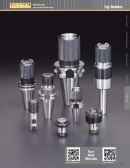
800-543-6237www.lyndexnikken.com<strong>Retention</strong> <strong>Studs</strong>Current PromotionScantheseQR CodesFeatured Video137<strong>Retention</strong> <strong>Studs</strong> R8, 5C, 3J, 16C Stub, Boring, Blank Tap Holders Drill Chucks Shell Mill Holders ER/TG/DA Collet Chucks End Mill Holders
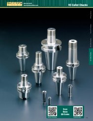
800-543-6237www.lyndexnikken.com<strong>Retention</strong> <strong>Studs</strong><strong>Retention</strong> <strong>Studs</strong> R8, 5C, 3J, 16C Stub, Boring, Blank Tap Holders Drill Chucks Shell Mill Holders ER/TG/DA Collet Chucks End Mill Holders<strong>Retention</strong> <strong>Studs</strong>138<strong>Retention</strong> studs come in many shapes and sizes. Many machining center manufacturers use different configurations oneach of their models. Please provide us with the following information when ordering retention studs:• Your machining center’s taper size (40, 50, etc) and flange type (CT or BT)• The brand name of your machining center• Its configuration (vertical or horizontal)• The model numberCAT <strong>Retention</strong> <strong>Studs</strong>• Class 3A UNC Thread• Magnetic particle crack tested• Tensile and shear requirements per ISO and JIS standard• All locations that make contact with ground spindlemechanism components are ground• Base of pullstud flange is ground to assure perpendicularalignment between pullstud and taper of toolholder• Tight pitch diameter tolerance helps maintain accurateconcentricity between threads and knob limiting theexpansion or flaring of the small end of the taper<strong>Retention</strong> Knob StyleJ D ABT <strong>Retention</strong> <strong>Studs</strong>• Class 4g6g metric thread• Magnetic particle crack tested• Tensile and shear requirements per JIS 6339• All locations of the pullstud that make contact withground spindle mechanism components are ground• Base of pullstud flange is ground to assure perpendicularalignment between pullstud and taper of toolholder• Ground Pilot and tight pitch diameter tolerance helpmaintain accurate concentricity between threads andknob limiting the expansion or flaring of the small end ofthe taperO-Ring TypeJIS DIN ANSI O-Ringin GrooveG T C FO-Ringin TaperO-Ringin C-BoreO-Ringon Face
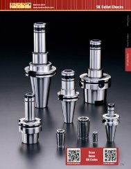
800-543-6237www.lyndexnikken.com<strong>Retention</strong> <strong>Studs</strong>CAT <strong>Retention</strong> <strong>Studs</strong>Part Number D d1 d2 L1 L2Note: “ * ” or “H” suffix denote retention studs supplied with a coolant hole.“B” suffix denotes balanceable toolholder retention studs.Angledegree W Thread O-Ring MaxTorque(Ft/lbs)C40-1500* 0.75 -- 0.276 0.79 1.03 75 0.28 5/8”-11 -- 85 DC40-1500(ISO)* 0.75 -- 0.276 0.79 1.03 75 0.16 5/8”-11 P9 85 D, TC40-4500 0.59 -- -- 0.99 1.26 45 0.12 5/8”-11 -- 85 JC40-4500(B) 0.59 0.64 -- 0.99 1.26 45 0.12 5/8”-11 -- 85 J, BC40-4500(H) 0.59 -- 0.177 0.99 1.26 45 0.12 5/8”-11 -- 85 JC40S-4500 0.59 -- -- 0.99 1.26 45 0.23 5/8”-11 -- 85 JC40S-4500(H) 0.59 -- -- 0.99 1.26 45 0.23 5/8”-11 -- 85 JC40-6000 0.59 -- -- 0.99 1.26 60 0.12 5/8”-11 -- 85 JC40-6000(B) 0.59 0.64 -- 0.99 1.26 60 0.12 5/8”-11 -- 85 J,BC40-6000(H) 0.59 -- 0.177 0.99 1.26 60 0.12 5/8”-11 -- 85 JC40S-6000 0.59 -- -- 0.99 1.26 60 0.23 5/8”-11 -- 85 JC40-9000 0.59 -- -- 0.99 1.26 90 0.12 5/8”-11 -- 85 JC40-9000(B) 0.59 0.64 -- 0.99 1.26 90 0.12 5/8”-11 -- 85 J, BC40-9000(H) 0.59 -- 0.177 0.99 1.26 90 0.12 5/8”-11 -- 85 JC40S-9000 0.59 -- -- 0.99 1.26 90 0.23 5/8”-11 -- 85 JC40-STD* 0.74 -- 0.276 0.44 0.64 45 0.12 5/8”-11 -- 85 AC40-STD(B) 0.74 0.64 0.276 0.44 0.64 45 0.12 5/8”-11 -- 85 A, BC40-HITACHI 0.59 0.64 0.197/0.157 0.992 1.26 45 0.12 5/8”-11 S-16 / P-5 85 J, GC40-MAZAK 0.59 0.625 -- 0.777 1.05 90 0.2 5/8”-11 -- 85 --C40-MITSUI 0.59 -- -- 0.59 0.87 90 0.2 5/8”-11 -- 85 JPS-381E 0.74 0.64 0.276 0.793 1.03 75 0.23 5/8”-11 S15 / P9 85 D, TPS-B641M 0.74 0.64 0.197 0.44 0.64 45 0.118 5/8”-11 S15 85 APS-806-1 0.75 0.79 0.24 0.787 1.023 75 0.276 5/8”-11 -- 85 DC50-1500* 1.1 -- 0.393 0.992 1.35 75 0.28 1”-8 S24 110 DC50-1500(ISO)* 1.1 -- 0.393 0.98 1.35 75 0.2 1”-8 -- 110 DC50-4500 0.9 -- -- 1.386 1.78 45 0.39 1”-8 -- 110 JC50-4500(B) 0.9 1.031 -- 1.386 1.78 45 0.39 1”-8 -- 110 J, BC50-4500(H) 0.9 -- 0.393 1.386 1.78 45 0.39 1”-8 -- 110 JC50-6000 0.9 -- -- 1.386 1.78 60 0.39 1”-8 -- 110 JC50-6000(B) 0.9 1.031 -- 1.386 1.78 60 0.39 1”-8 -- 110 J, BC50-6000(H) 0.9 -- 0.393 1.386 1.78 60 0.39 1”-8 -- 110 JC50-9000 0.9 -- -- 1.386 1.78 90 0.39 1”-8 -- 110 JC50-9000(B) 0.9 1.031 -- 1.386 1.78 90 0.39 1”-8 -- 110 J, BC50-9000(H) 0.9 -- 0.393 1.386 1.78 90 0.39 1”-8 -- 110 JC50-STD* 1.14 -- 0.46 0.7 1 45 0.2 1”-8 -- 110 AC50-STD(B) 1.14 1.031 0.46 0.7 1 45 0.2 1”-8 -- 110 A, BC50-HITACHI 0.9 -- -- 1.385 1.78 90 0.39 1”-8 -- 110 JC50-HITACHI(OH) 0.9 -- 0.118 1.385 1.78 90 0.39 1”-8 -- 110 J, FC50-MAKINO 0.9 0.984 0.236 1.378 1.772 45 0.39 1”-8 P22 110 JC50-MAZAK 0.91 0.91 0.91 0.91 0.91 0.91 0.91 1”-8 -- 110 --C50-MITSUI 0.94 -- -- 0.905 1.22 90 0.2 1”-8 -- 110 JC50-OKUMA(OH) 0.906 1.023 0.275 1.378 1.772 60 0.39 1”-8 S24 110 JPS-P14 0.94 -- 0.314 0.905 1.22 90 0.39 1”-8 PS-P13 110 Dwith holePS-B61 0.9 1.023 0.236 1.377 1.77 60 0.39 1”-8 N24 110 JA = ANSI Style KnobB = Balanced Knob (With Pilot Dia.)C = O-Ring in C-BoreD = DIN Style KnobF = O-Ring on FaceG = O-Ring in GrooveJ = JIS Style KnobT = O-Ring in TaperJ D AStyleJIS DIN ANSI O-Ringin GrooveThe drawing above details the fivecritical dimensions needed todetermine which retention stud isrequired. Please have thesedimensions ready when you placeyour order, so that we may easilyand quickly determine whichretention stud is needed for yourmachining center.G T C FO-Ringin TaperO-Ringin C-BoreO-Ringon Face139<strong>Retention</strong> <strong>Studs</strong> R8, 5C, 3J, 16C Stub, Boring, Blank Tap Holders Drill Chucks Shell Mill Holders ER/TG/DA Collet Chucks End Mill Holders
800-543-6237www.lyndexnikken.com<strong>Retention</strong> <strong>Studs</strong><strong>Retention</strong> <strong>Studs</strong> R8, 5C, 3J, 16C Stub, Boring, Blank Tap Holders Drill Chucks Shell Mill Holders ER/TG/DA Collet Chucks End Mill HoldersBT <strong>Retention</strong> <strong>Studs</strong>Part Number D d1 d2 L1 L2Angledegree W Thread O-Ring Max Torque(Ft/lbs)PS-M10 0.55 0.492 -- 0.669 0.87 45 0.12 M12P1.75 -- 40 DPS-16 0.43 0.492 -- 0.709 0.905 45 0.2 M12P1.75 -- 40 JPS-17 0.43 0.492 -- 0.709 0.905 60 0.2 M12P1.75 -- 40 JPS-19 0.512 0.492 -- 0.886 1.102 60 0.2 M12P1.75 -- 40 JPS-130E 0.43 0.492 0.157 0.709 0.905 45 0.2 M12P1.75 P9 40 JPS-132 0.43 0.492 0.157 0.709 0.905 45 0.2 M12P1.75 P9 40 --PS-801 0.472 0.492 -- 0.724" 0.921 75 0.2 M12P1.75 -- 40 JB30-4500 0.43 0.492 -- 0.709 0.91 45 0.19 M12P1.75 -- 40 JB30-6000 0.43 0.492 -- 0.709 0.91 60 0.19 M12P1.75 -- 40 JPS-1 0.591 0.669 -- 1.102 1.378 45 0.23 M16P2 -- 40 JPS-70 0.748 0.669 -- 1.102 1.378 45 0.2 M16P2 -- 40 JPS-P5-1 0.591 0.669 -- 0.708 0.984 90 0.2 M16P2 -- 40 JPS-G5 0.591 0.669 -- 1.165 1.165 90 0.2 M16P2 -- 40 --PS-G58 0.74 0.669 -- 0.752 0.752 45 0.2 M16P2 -- 40 APS-805 0.748 0.669 -- 0.905 1.142 75 0.28 M16P2 -- 40 JPS-G51 0.74 0.669 0.275 0.512 0.752 45 0.12 M16P2 -- 40 APS-G510 0.74 0.669 0.275 0.752 0.752 45 0.12 M16P2 PS-51 40 APS-354 0.594 0.669 0.157 0.157 1.55 45 0.19 M16P2 -- 40 JPS-G52 0.74 0.275 0.669 0.44 0.64 45 0.12 M16P2 -- 40 APS-364 0.59 0.157 0.669 1.116 1.44 45 0.23 M16P2 -- 40 JB40-1500* 0.75 0.669 0.275 0.905 1.14 75 0.27 M16P2 -- 85 DB40-1500(R) 0.75 0.669 0.275 0.905 1.14 75 0.27 M16P2 AS568-015 85 DB40-1500(ISO)* 0.75 0.669 0.275 0.9 1.14 75 0.16 M16P2 P9 85 D, TB40-4500 0.59 0.669 -- 1.102 1.37 45 0.23 M16P2 -- 85 JB40-4500(H) 0.59 0.669 0.181 1.102 1.37 45 0.23 M16P2 -- 85 JB40-6000 0.59 0.669 -- 1.102 1.37 60 0.23 M16P2 -- 85 JB40-6000(H) 0.59 0.669 0.181 1.102 1.37 60 0.23 M16P2 -- 85 JB40-9000 0.59 0.669 -- 1.102 1.37 90 0.23 M16P2 -- 85 JB40-9000(H) 0.59 0.669 0.181 1.102 1.37 90 0.23 M16P2 -- 85 JB40-BRIDGEPORT 0.74 0.669 0.275 0.552 0.75 45 0.13 M16P2 -- 85 AB40-FADAL 0.74 0.669 -- 0.552 0.75 45 0.24 M16P2 -- 85 AB40-STD* 0.74 0.669 0.275 0.43 0.64 45 0.12 M16P2 -- 85 APS-874 0.75 0.669 0.236 0.905 1.142 75 0.28 M16P2 AS568-015 / P9 85 D, TPS-366E-1 0.75 0.669 0.276 0.905 1.142 75 0.16 M16P2 -- 85 D, TPS-50 0.906 0.984 -- 0.984 2.756 45 1.38 M24P3 -- 85 --PS-G45 1.14 0.984 -- 0.992 0.692 45 0.2 M24P3 -- 85 APS-B1 0.866 0.984 -- 1.063 2.835 60 1.38 M24P3 -- 85 --PS-809 1.102 0.984 -- 0.984 1.339 75 0.28 M24P3 -- 85 DPS-C 0.827 0.984 -- 2.169 2.484 45 1.14 M24P3 -- 85 --PS-810 1.102 0.984 0.393 0.984 1.339 75 0.28 M24P3 -- 85 DPS-816-1 1.102 0.984 0.236 0.984 1.339 75 0.28 M24P3 P21 85 DPS-833 1.102 0.984 0.216 0.984 1.339 75 0.28 M24P3 P9 / P21 85 D, TPS-G41 1.14 0.984 0.393 0.992 0.692 45 0.2 M24P3 -- 85 APS-P16 0.945 0.984 0.314 0.905 1.22 90 0.2 M24P3 -- 85 JB50-4500 0.91 0.984 -- 1.377 1.77 45 0.39 M24P3 -- 110 JB50-4500(H) 0.91 0.984 0.275 1.377 1.77 45 0.39 M24P3 -- 110 JB50-6000 0.91 0.984 -- 1.377 1.77 60 0.39 M24P3 -- 110 JB50-6000(H) 0.91 0.984 0.275 1.377 1.77 60 0.39 M24P3 -- 110 JB50-9000 0.91 0.984 -- 1.377 1.77 90 0.39 M24P3 -- 110 JB50-9000(H) 0.91 0.984 0.275 1.377 1.77 90 0.39 M24P3 -- 110 JB50-MITSUI 0.95 0.984 -- 0.905 1.22 90 0.2 M24P3 -- 110 J140StyleNote: “ * ” or “H” suffix denoteretention studs suppliedwith a coolant hole. “B”suffix denotes balanceabletoolholder retention studs.JIS DIN ANSIO-Ringin GrooveJ D AG T C FO-Ringin TaperO-Ringin C-BoreO-Ringon FaceA = ANSI Style KnobB = Balanced Knob (With Pilot Dia.)C = O-Ring in C-BoreD = DIN Style KnobF = O-Ring on FaceG = O-Ring in GrooveJ = JIS Style KnobT = O-Ring in Taper